Article

Compressive Property and Energy Absorption Capacity of Mg-Ceramic-Ni Foamsat Various Temperatures

Key Laboratory of Automobile Materials (Ministry of Education), College of Materials Science and Engineering, Jilin University, Changchun 130022, China
*
Author to whom correspondence should be addressed.
These authors contributed equally to this work.
Metals 2022, 12(4), 689; https://doi.org/10.3390/met12040689
Submission received: 21 February 2022 / Revised: 21 March 2022 / Accepted: 22 March 2022 / Published: 18 April 2022

Abstract

:
Mg–Ceramic–Ni hybrid foams were fabricated via continuousdepositing micro-arc oxidation (MAO) ceramic coating and electroless Ni coating on the surface of the AZ91D foam struts. Mechanical tests from room temperature (RT) to 300 °C were carried out to evaluate the compressive properties and energy absorption capacities of two types of foams, i.e., AZ91D alloy foams and corresponding hybrid foams. The effect of composite coatings and test temperature on the compressive property of the foams was studied. The experimental results show that the MAOand Ni coatings enhance the Mg foam struts, resulting in high compressive strength and energy absorption capacity at each testing temperature. In addition, the compressive properties are also depending on testing temperature. The different mechanical responses of the composite foams under various temperature conditions are mainly attributed to the different deformation behaviors and failure modes of the foam struts, which are confirmed by scanning electron microscopy (SEM) observation.

1. Introduction

Mg foams have attracted wide attention overrecentyears due to their desirable properties, such as low density, high damping, good energy absorption capacity, electromagnetic shielding, and biocompatible property [1,2]. In the automobile field, a high-performance Mg foam is required as energy absorbing material for anti-collision components. However, the low mechanical properties at room temperature (RT) and elevated temperatures of the Mg have limited the industrial applications of the Mg foams [3,4,5]. Therefore, the improvement in compressive properties, which is commonly adopted to assess the usability of Mg foams [6], is an important issue.
Previous investigationshave revealed that the compressive properties of metallic foams can be improved by several methods: particle reinforcement, the addition of alloy elements, surface treatment, and so on [6,7,8]. Among these methods, surface treatment is effective in improving the compressive properties of metallic foams. Some researchers have paid attention to the depositing of a coating on the surface of the foam struts, such as electroless deposition and micro-arc oxidation (MAO) [9,10,11,12,13]. T. Abdulla et al. [13] applied MAO technology on the open-cell Al foams and found that the yield stress of Al foams can be improved by a reasonable thickness. Silvio et al. [3] deposited an Ni coating on Al foams and found that Ni coating enhances the yield strength at RT and elevated temperatures. For Mg foams, Wang et al. [14] have successfully fabricated a Zn coating on Mg foams and reported that this brought high compressive strength and corrosion resistance. Rua et al. [11] applied the MAO coating on AZ31 foams, and the results showed that coated and uncoated foams exhibited similar compressive strengths. Our recent investigation also suggested that Ni–P coating could increase the compressive strength of Mg foams at RT [9].
As mentioned above, these studies mostly deal with the effect of a single layer of coating on the metallic foams. Currently, several studies of the composite coatings covering the bulk Mg alloy show that a double layer of coating has superior corrosion properties compared with a single layer. Song et al. [15] prepared high-quality composite coatings by employing Ni-P coating and MAO coating on AZ91D alloy. It has been suggested that composite coatings are beneficial to improve the corrosion resistance of the AZ91D metallic alloy. Zhang et al. [16] found that the electroless Ni-P/Ni-B composite coatings deposited on the surface of AZ91D alloy have a high degree of hardness and corrosion resistance. Ezhilselvi et al. [17] have confirmed that the MAO/Ni-P composite coatings on the AZ31 alloy heighten corrosion resistance effectively. Considering the engineering application of porous materials, the compressive properties of the Mg alloy foams should also be improved along with the enhancement of corrosion resistance. Though some investigations have applied single coating to Mg alloy foams, studies on composite coatings on reinforced Mg foams are rarely reported.
In the present work, a type of composite coatings composed of a Ni electroless layer and a MAO ceramic layer, was deposited on the surface of AZ91D alloy foams to fabricate Mg–Ceramic–Ni hybrid foams. The effects of composite coatings on the compressive properties and energy absorption capacities of the foams were studied. The effect of temperature on the mechanical properties was also analyzed. The deformation behavior and failure mechanisms of the AZ91D hybrid foams at different temperatures were discussed by observing fracture morphologies of the foam struts.

2. Materials and Methods

2.1. Specimen Fabrication

In this study, the commercial AZ91D alloy was used as the basal material, and industrial spheroidal CaCl2 particles are adopted to prepare a porous AZ91D alloy. AZ91D is one of the most commonly applied and cost-effective Mg alloy [18,19]. The details of the preparation process of the open-cell AZ91D alloy foams, similar to that of pure Mg foams, are given in our previous work [9].
The surface treatment on the AZ91D alloy foams includes the MAO process and the electroless plating process. Before the surface treatment, the AZ91D alloy foams were washed in an ultrasonic bath to remove the dirt and residue on the surfaces; they were thenrinsed with deionized water and dried in the air. The MAO process on the AZ91D alloy foams was conducted by MAO-50 equipment (Qiangshen Inc., Xi’an, China). The bath compositions and process parameters of the MAO process are presented in Table 1. After the MAO process, the electroless plating process that deposits the Ni–P layer on the MAO layer includes the following processes: alkaline cleaning, acid pickling, fluoride activation, and then electroless plating. The bath compositions and process parameters used in the electroless plating process are presented in Table 2.

2.2. Compressive Test

The compressive tests of the AZ91D alloy foams and the AZ91D hybrid foams were conducted using a universal mechanical machine (Instron 5869, Instron Inc. in Shanghai, Shanghai, China) equipped with a high-temperature furnace. A sample with a size of ~12 mm × 12 mm × 28 mm was used for the compressive test. The testing strain rate was 1 × 10⁻³ s−1 and the testing temperatures were room temperature (RT), 100 °C, 200 °C and 300 °C. Each specimen before the high-temperature tests was preheated to the testing temperature and then held for 10 min in the furnace to achieve a stable temperature environment. Each compressive condition was carried out on more than three specimens to ascertain data reproducibility.
The parameters of the compressive strength and the energy absorption capacity were measured to assess the mechanical properties of the AZ91D alloy foams and the AZ91D hybrid foams. The compressive strength of the metallic foams is defined as the first peak stress when the specimen is yielding beyond the linear-elastic region, or the stress at a strain of 0.05 where the compressive curve is smooth without stress yield [9,20]. The energy absorption capacity of the metallic foams can be calculated by the following formula [21]:
W = 0 ε σ d ε
where σ and ε are the compressive stress and the compressive strain, respectively, and W is the energy absorption capacity.

2.3. Characterizations

Microstructures on the surface and the cross-section of the AZ91D hybrid foamsand the morphologies of the fracture surfaces after compressive tests were characterized by scanning electron microscopy (SEM, VEGA3, TESCAN Corp., Brno, Czech Republic). Chemical compositions and phases of the AZ91D hybrid foams were analyzed and determined by energy-dispersive X-ray spectroscopy (EDS, Link-ISIS, British Oxford, UK) and X-ray diffraction (XRD, D/Max2500, RIGAKU Corp., Yamanashi, Japan).

3. Results

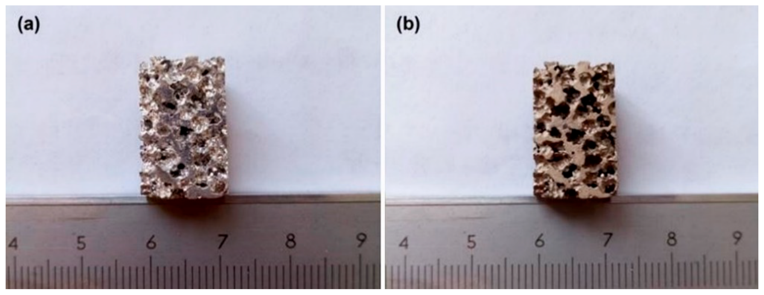
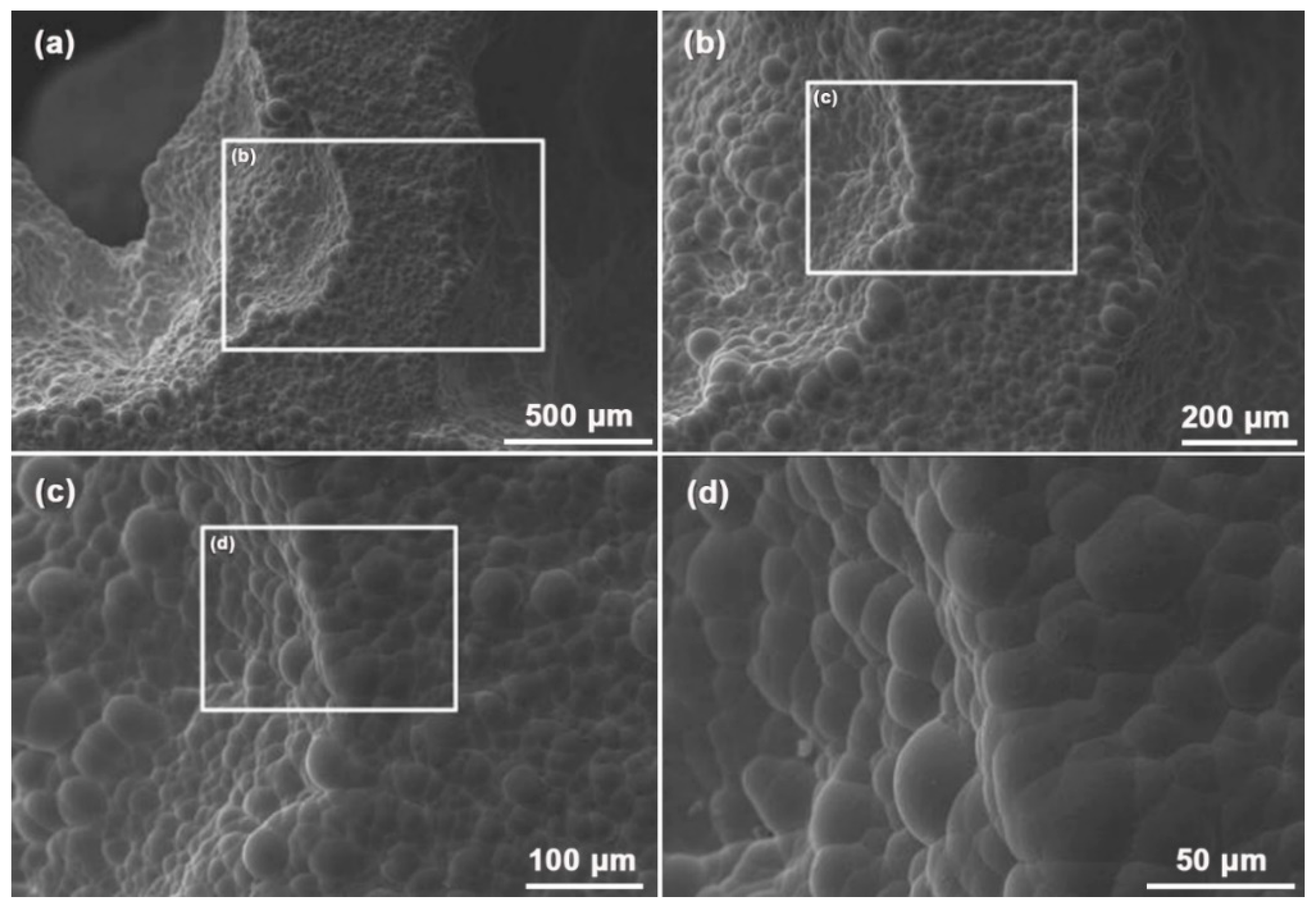
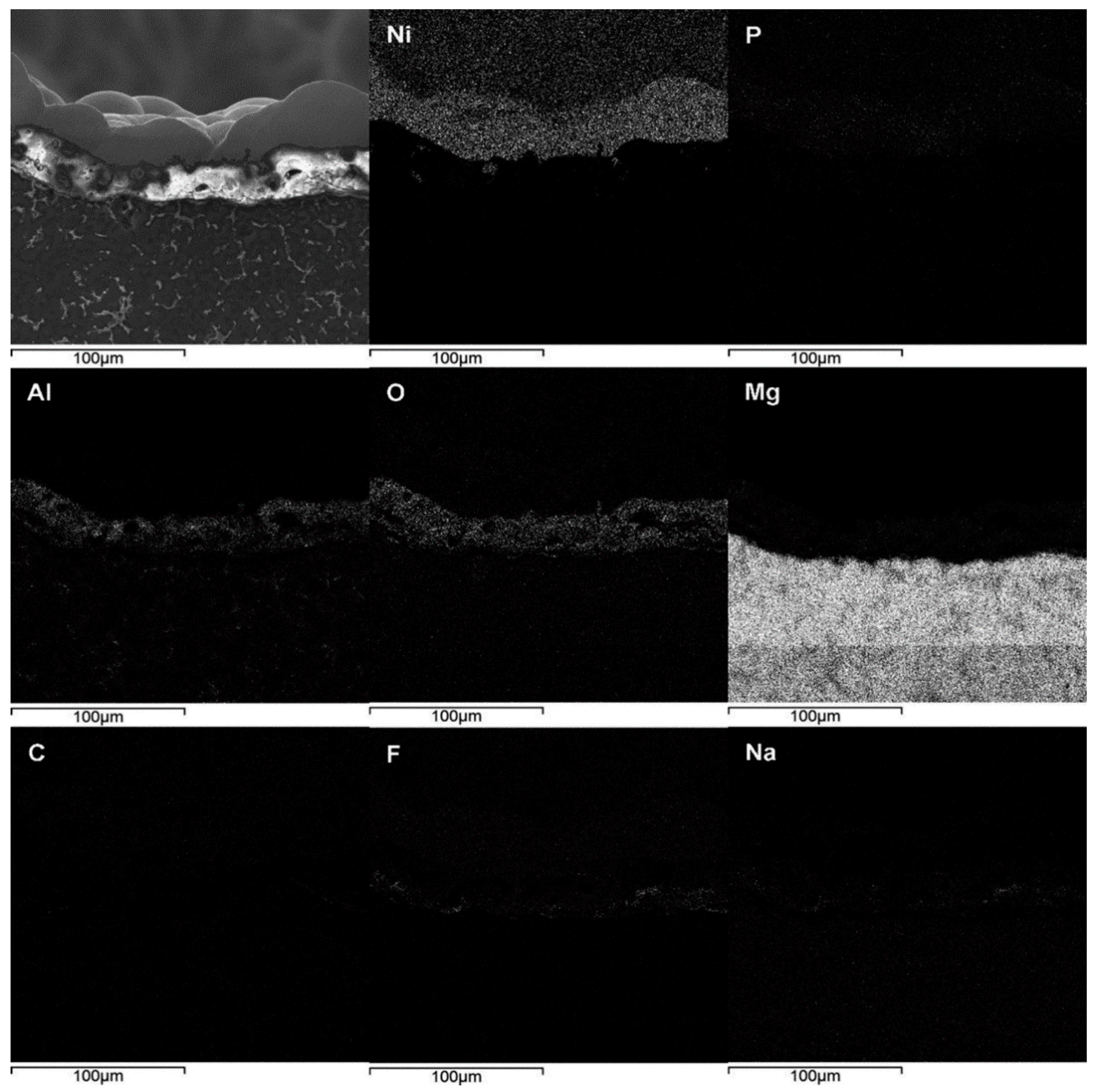
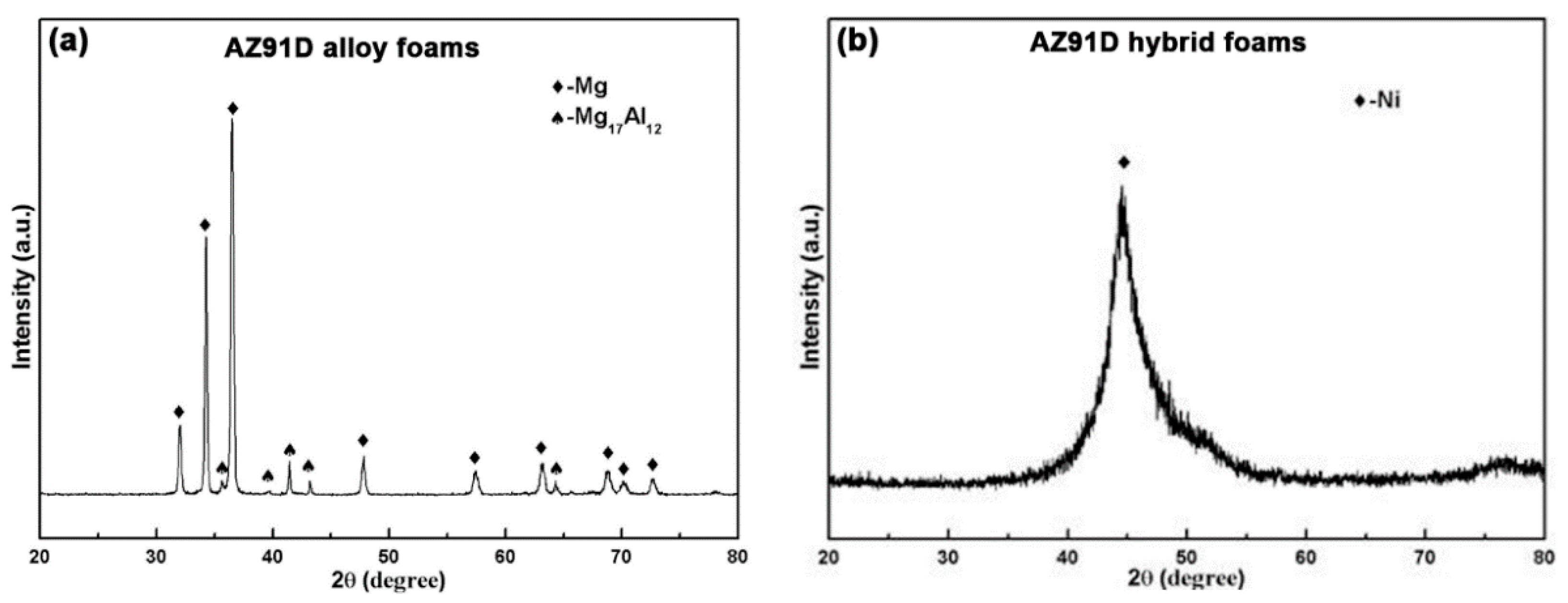
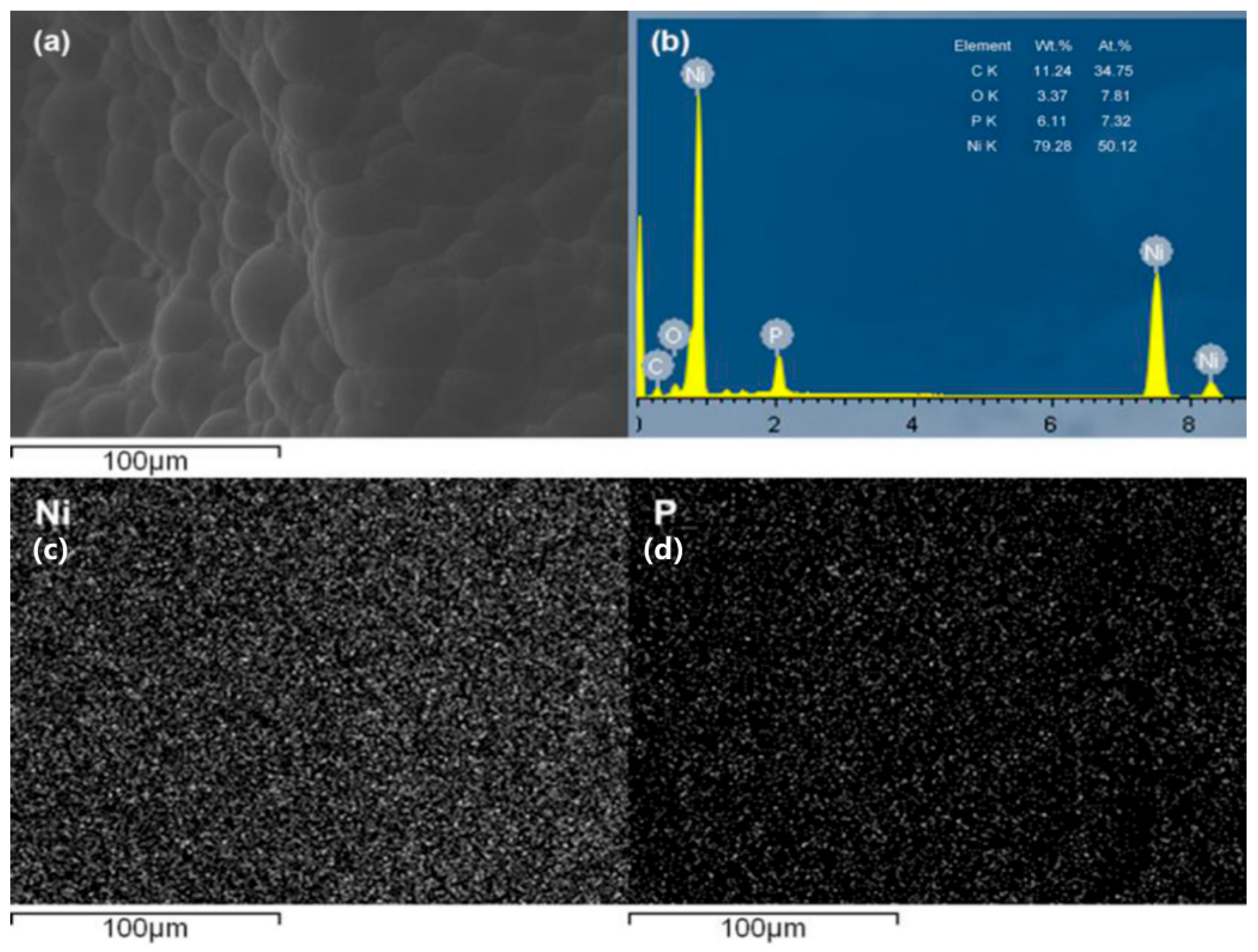
3.1. Macroscopic Morphologiesand Microstructure

Figure 1 presents the macroscopic morphologies of the AZ91D alloy foams and the AZ91D hybrid foams. Both kinds of the foams show typical open-cell structures. In addition, different metallic lusters of the two contrast foams indicate that the duplex coating has been well deposited on the surface of the foam struts.
Figure 2 displays the microstructure of the AZ91D hybrid foams. It is clear in Figure 2a that the hybrid foams are completely covered by the composite coatings. High magnifications as shown in Figure 2b,c exhibitthat those composite coatings are continuous, without obvious defects, and their surface exhibits typical nodular morphology. The nodular diameter measured from Figure 2d is in the range of 15–45 μm. Such high-quality composite coatings mainly arise from the MAO layer that provides more depositing sites for nickel.
Figure 3 shows the EDS analysis of the surface for the AZ91D hybrid foams. The EDS results demonstrate that the chemical compositions of the surface mainly include Ni and P elements. The content of the P elements is in the range of 6–10 wt.%, indicating that such a coating is a medium phosphorus coating [22]. The element distribution indicates that the Ni and P elements are dispersed without segregation in the coating, while the Mg and Al elements existed in the AZ91D substrate. In addition, the element of the MAO layer is not detected, which confirms that the Ni–P layer is densely deposited on the MAO layer. Owing to the high density of Ni, the density of the foams was increased by about 46%.
Figure 4 shows the microstructure of the cross-section for the AZ91D hybrid foams. The composite coatings on the cross-section display a double-layer structure, which includes an intermediate layer and a top layer from the substrate to the surface. The intermediate MAO layer is generated from the AZ91D substrate, while the top Ni-P layer grows from the MAO layer. The average thickness of the MAO layer and Ni–P layer is around 25 and 32 μm, respectively. Some micro-pores are also observed in the MAO layer. These micro-pores are mainly ascribed to the micro-arc discharges. During the MAO process, the micro-arc discharges can produce an instantaneous high temperature and then melt the substrate, resulting in the generation of the molten oxide ceramics [23]. Consequently, the MAO layer shows good adhesion with the substrate because it is metallurgically deposited on the metal substrate [24]. It is noted that parts of the Ni–P layer are embedded in the micro-pores of the MAO layer, as displayed in Figure 4d, indicating that the Ni–P layer and MAO layer bond together by mechanical interlocking.
Figure 5 displays the EDS analysis of the cross-section for AZ91D hybrid foams. The EDS results illustrate that the composite coatings on the cross-section are mainly composed of P, Ni, Al, O, and Mg elements. The Mg and Al elements mainly come from the AZ91D substrate and the MAO layer, while the O elements are mostly from the MAO layer. Meanwhile, it is observed that some Ni elements are also observed in the MAO layer, confirming the mechanical interlocking between the Ni–P layer and the MAO layer. In addition, the EDS results show the presence of C, F, and Na elements. The C elements mainly come from the conductive adhesives, while the F and Na elements may derive from the MAO electrolyte.
Figure 6 presents the XRD patterns of the AZ91D alloy foams and the AZ91D hybrid foams. From Figure 6a, it can be identified that the AZ91D alloy foams mainly consist of the α-Mg matrix and the β-Mg17Al12 eutectic phase, while the XRD pattern for the AZ91D hybrid foams in Figure 6b illustrates a sharp diffraction peak at around 45°, which corresponds to the diffraction peak of (111) planes of Ni. The peak intensity with a wide region indicates that the Ni–P layer is mainly a mixture of nanocrystalline plus amorphous elements. The absence of other diffraction peaks also confirms strongly that a thick and dense Ni–P top layer of high-quality is deposited on the MAO intermediate layer.

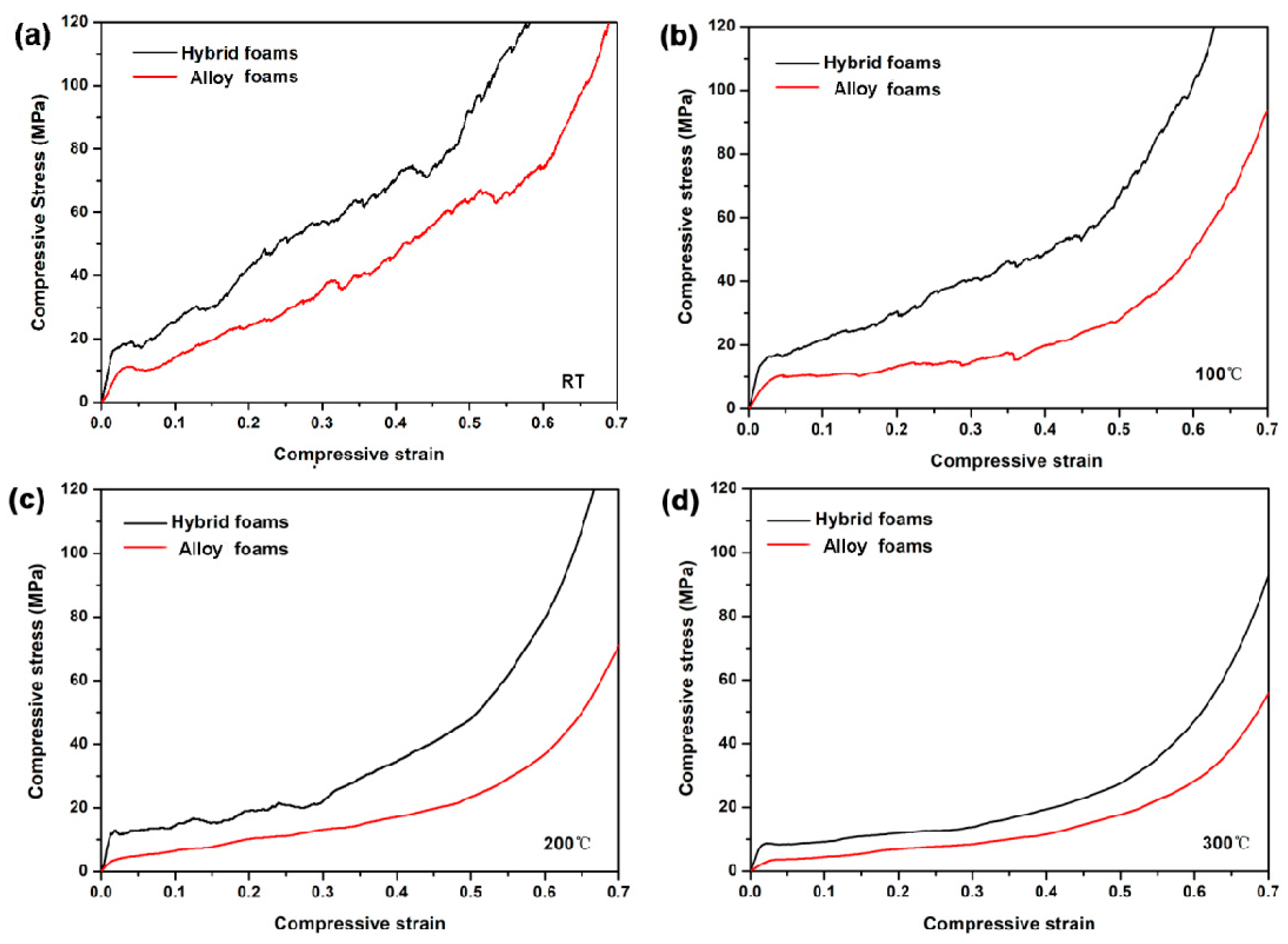
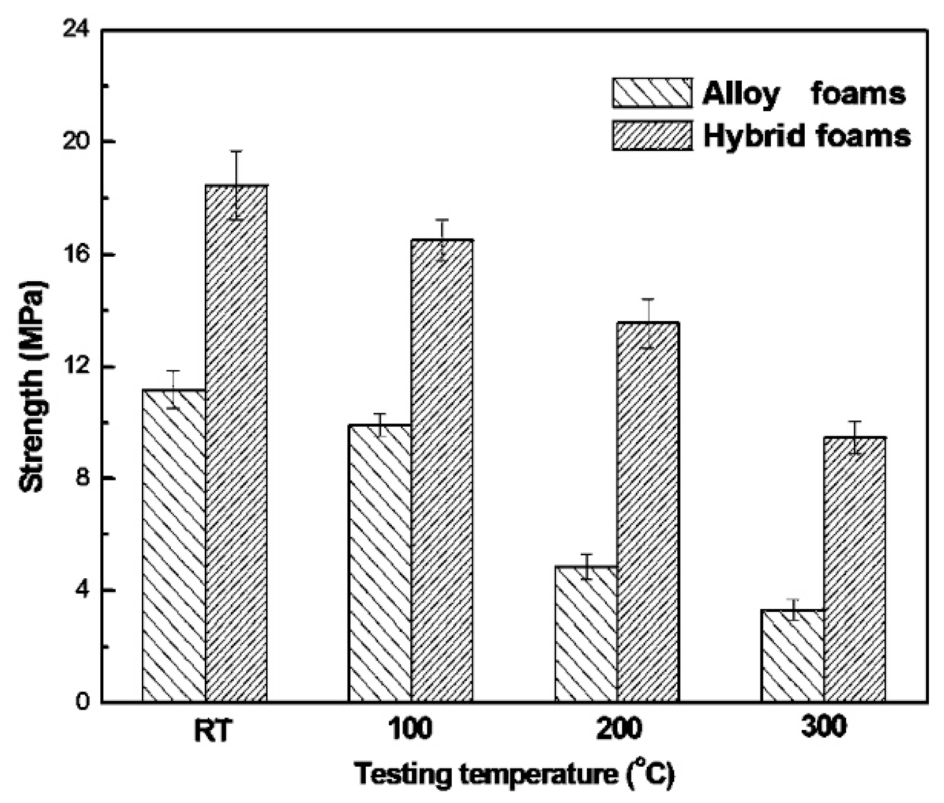
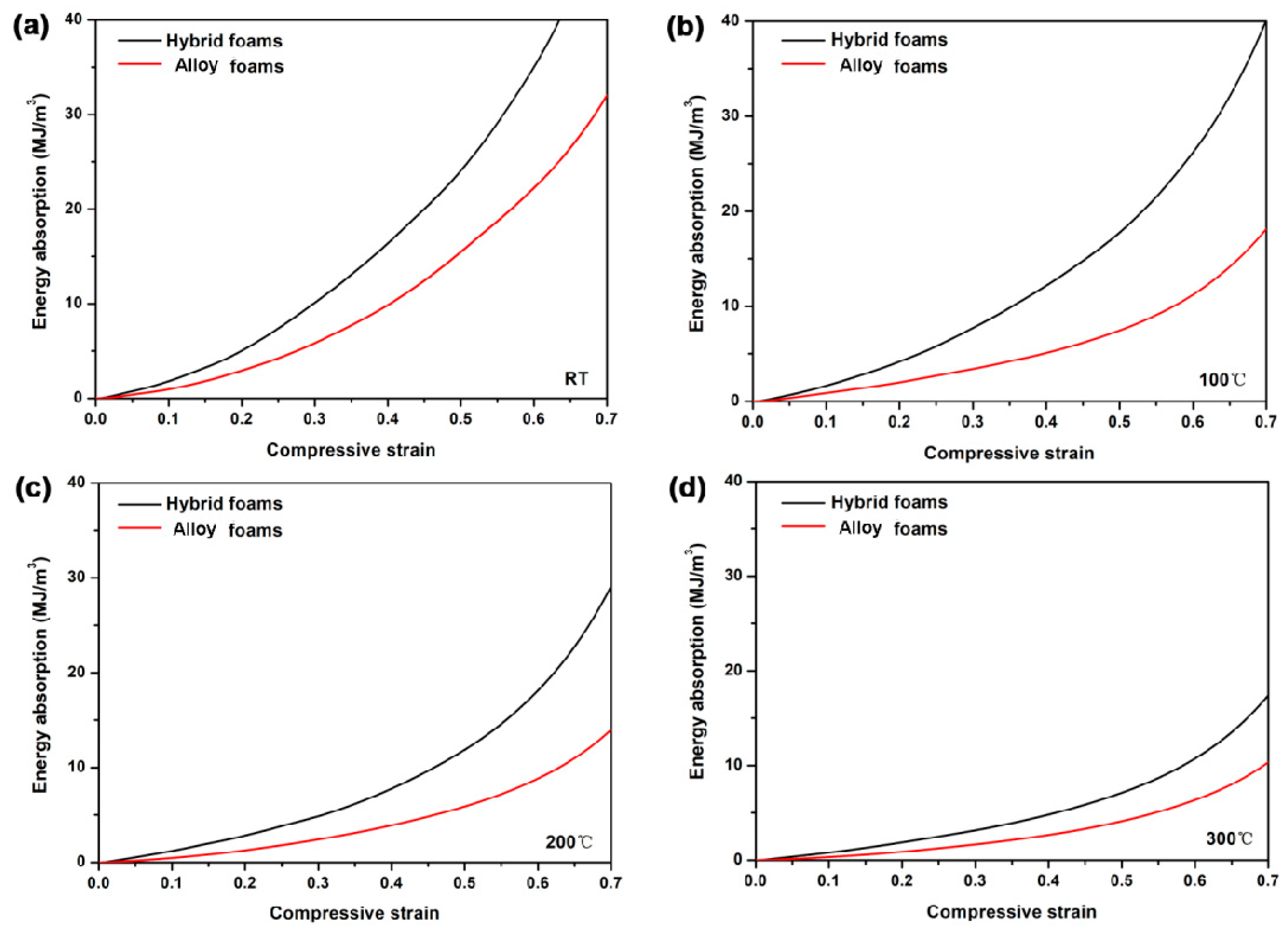
3.2. Compressive Properties

Figure 7 displays the compressive stress–strain curves of the AZ91D alloy foams and the AZ91D hybrid foams from RT to 300 °C. Generally, the compressive stress–strain curves of metallic foams show three typical stages, i.e., a linear-elastic stage, a plateau stage, and a densification stage [9,25]. In this study, Figure 6a shows that the stress–strain curves of the experimental foams gained from compression tests at RT are fluctuating, and the expected plateau is almost missing. The study performed by Florek shows that the structural deformation mechanism in foams affects the mechanical response. The sudden stress drop in the stress–strain curve is attributed to brittle cell walls cracking, while increasing stress before final densification is caused by the ductile cell walls bending [26]. The hybrid foams exhibit more significant stress fluctuations at the plateau stage as compared with the alloy foams, indicating more cracking of the foam strut. In addition, with increasing temperature, the stress fluctuations for the two types of foams gradually become weak, which indicates compressive deformation behavior, which changes at different temperatures.
The compressive strengths of the AZ91D alloy foams and the AZ91D hybrid foams from RT to 300 °C can be compared in Figure 8. The compressive strengths of the hybrid foams are much higher than those of the alloy foams at all of the testing temperatures. This reveals that the composite coatings can effectively enhance the compressive strength of the alloy foams at each testing temperature. Zhang et al. [16] have suggested that the Ni–P coating significantly increases the Vickers Hardness (HV) of AZ91D alloy from 100 HV to 587 HV, which is attributed to the high strength of Ni–P coating. Meanwhile, our previous study [27] has reported that the Ni–P coating provides the open-cell Al foams with a good strengthening effect on heat resistance, suggesting that the Ni–P coating possesses high thermal stability. Besides the high strength and thermal stability of the Ni–P coating, the MAO ceramic coating also plays the same role in the compressive strength of the Al foams at RT and elevated temperatures [28]. Owing to the high performance of Ni–P and MAO layers at RT and elevated temperatures, the mechanical properties of the foam struts are accordingly enhanced by the composite coatings, resulting in higher compressive strength of the hybrid foams than that of the alloy foams. Moreover, with the increase in the temperature from RT to 100 °C, 200 °C, and 300 °C, the compressive strength of the alloy foams is gradually decreased by 11.44%, 56.48%, and 70.51%, while that of the hybrid foams is decreased by 10.61%, 26.68%, and 48.81%, respectively. The smaller reduction ratio of the compressive strength for the hybrid foams at elevated temperatures also confirms the high strength and thermal stability of the composite coatings.
Figure 9 presents the energy absorption capacity–compressive strain curves of the alloy foams and the hybrid foams from RT to 300 °C. The energy absorption capacity of the hybrid foams is much higher than that of the alloy foams at RT and elevated temperatures. The energy absorption capacities of both alloy foams and hybrid foams are also gradually reduced with the increase in temperature. When the temperature increases from RT to 100 °C, 200 °C, and 300 °C, the decrease ratio of the energy absorption capacity for the alloy foams is 51.87%, 61.87%, and 73.38%, while that for the hybrid foams is 26.17%, 48.23%, and 67.43%, respectively. The higher energy absorption capacity and the smaller decrease ratio of the hybrid foams indicate that the composite coatings can raise the energy absorption capacity of the alloy foams at each testing temperature.

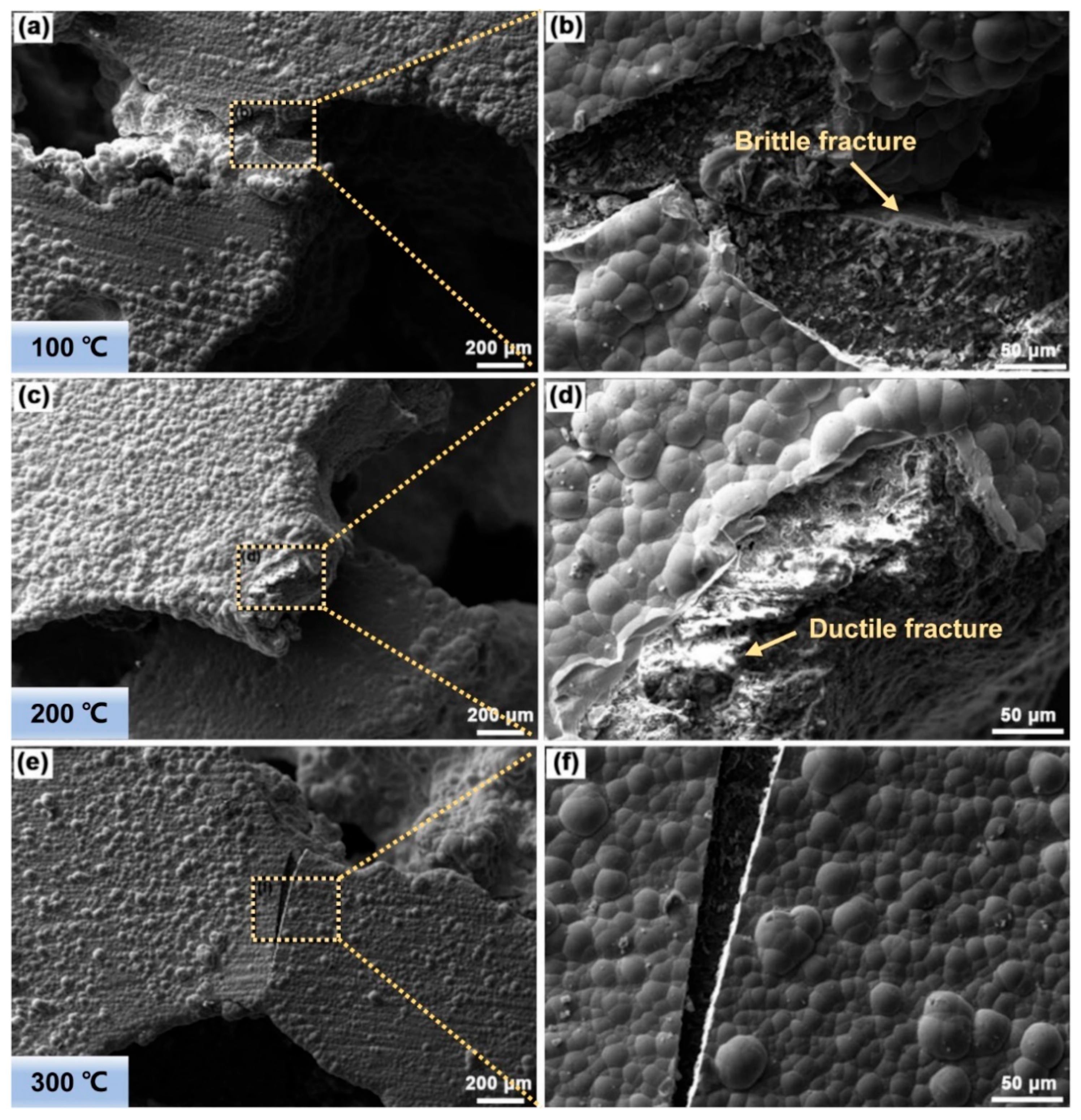
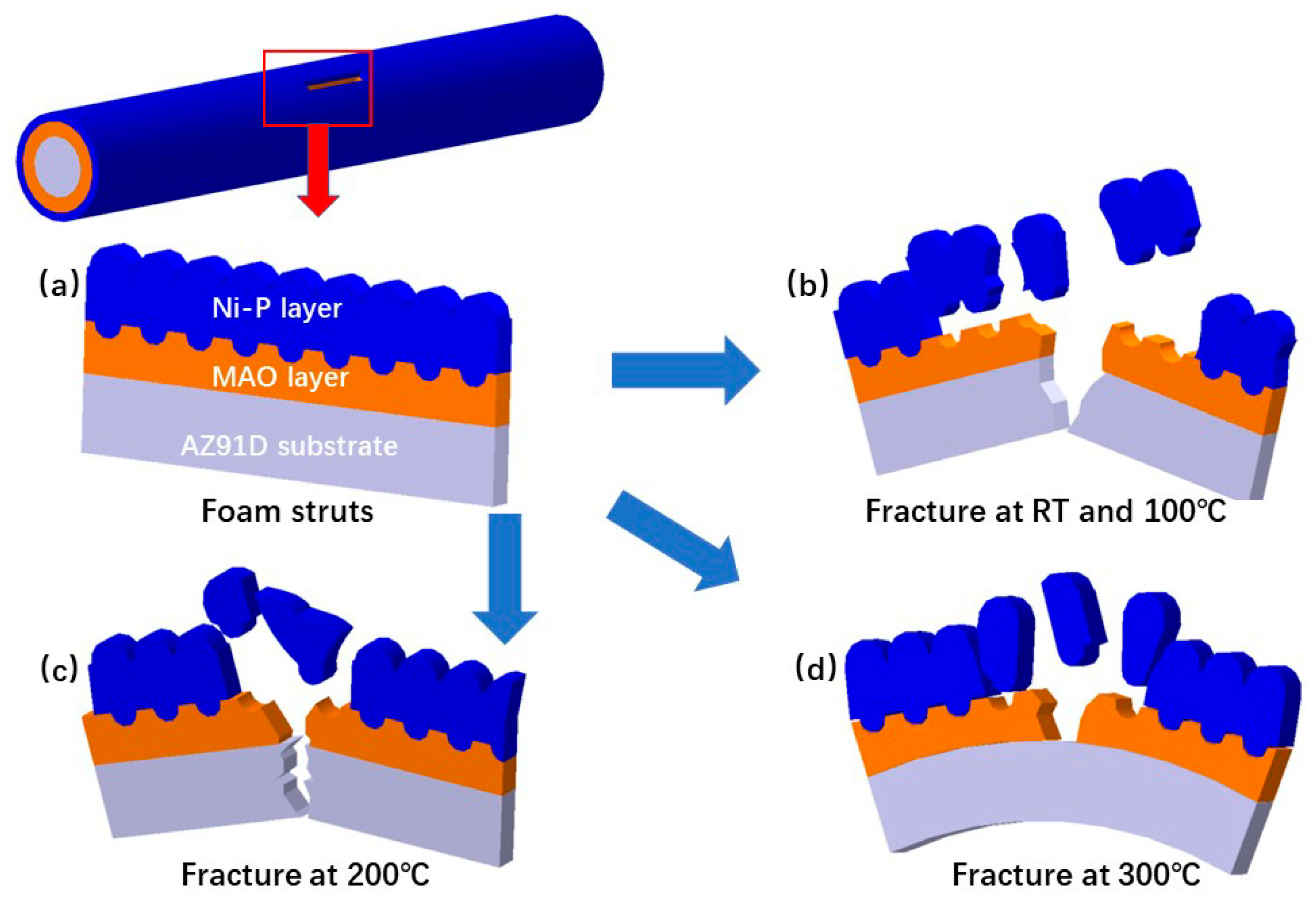
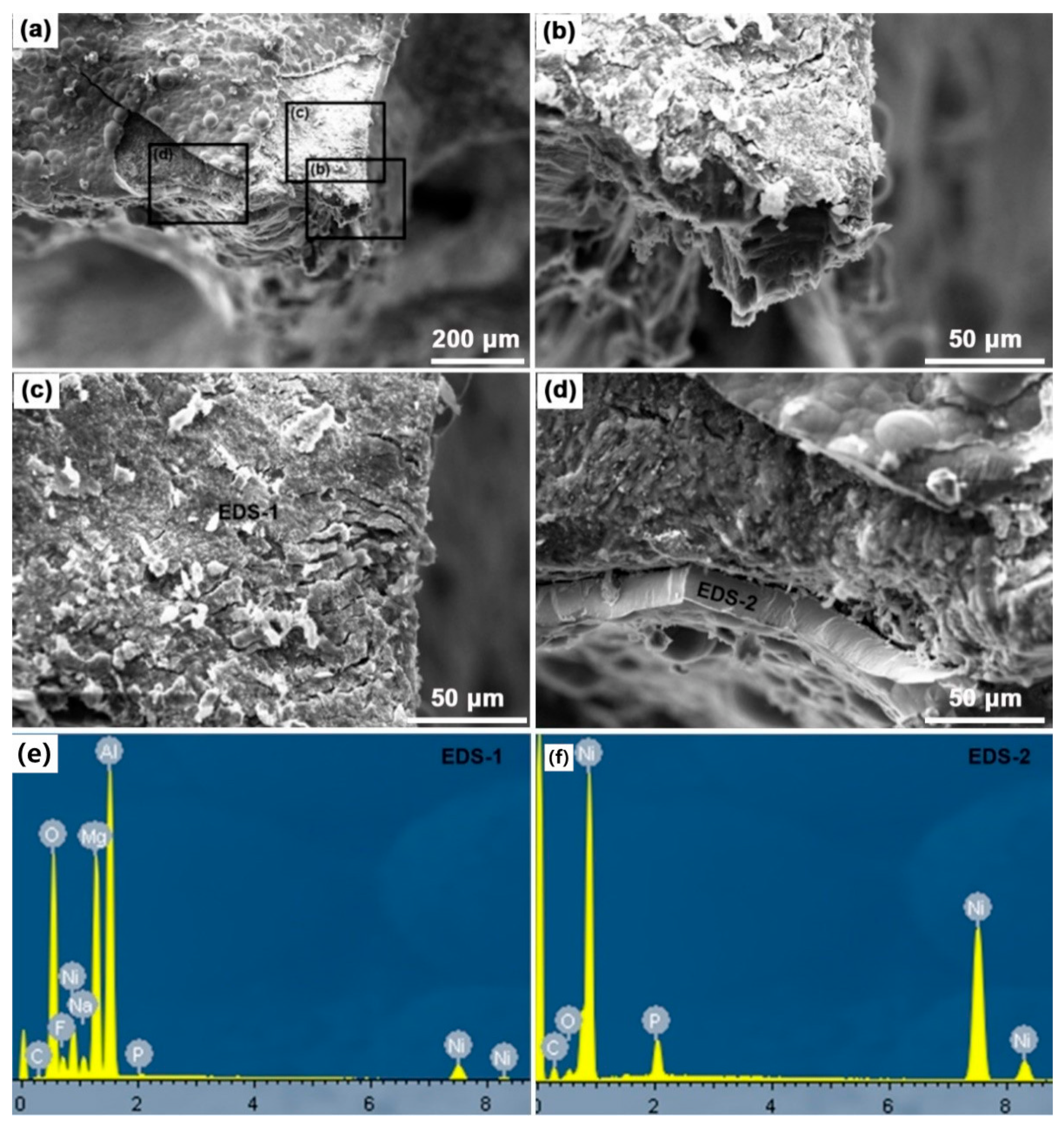
3.3. Deformation Behavior and Failure Modeof the Foam Struts

Figure 10 shows the fracture morphologies and the EDS analysis of the hybrid foams at RT. It is observed that the fracture mainly occurs at the foam struts, and the failure of the foam struts can be divided into three typical types. For one type, the fracture morphology is a flat plane on the substrate, and Figure 10b indicates that the substrate exhibits a typical brittle fracture mode. For the other type, the straight and large cracks, asshown in Figure 10c,d, also demonstrate the brittle rupture characteristics of the MAO layer and Ni-P layer, as confirmed by the EDS-1 and EDS-2 analyses, respectively. For the final type, the Ni–P layer was peeled off from the MAO layer, as shown in Figure 10a, and this indicates that the mechanical interlocking between the MAO layer and the Ni–P layer is weaker than the metallurgical bonding between the MAO layer and the substrate.
Figure 11 shows the fracture morphologies of the hybrid foams at elevated temperatures (100 °C, 200 °C, and 300 °C). At 100 °C, as shown in Figure 11a,b, the brittle fracture occurs at the Ni–P layer and the substrate, as indicated by the straight crack boundaries. At 200 °C, as displayed in Figure 11c,d, the crack boundaries of the substrate transform into bent or not straight forms, which indicates the softening effect of the temperature on the AZ91D substrate. At 300 °C, in Figure 11e,f, the straight crack boundary on the composite coatings confirms the brittle fracture for the composite coatings even at 300 °C. However, AZ91D substrate shows a softening behavior, which indicates that the bending or/and buckling deformation mode would increase at elevated temperature, an observation agreeing with the previous investigations [29,30].
Based on the SEM observations of the fracture morphologies, it can be concluded that the failure of the hybrid foams is mostly attributed to the failure of the foam struts, including the fracture modes of the substrate and the composite coatings. The different failure characteristics of the foam struts at all of the testing temperatures can be clearly illustrated by the schematic diagrams of the crack features of the substrate and the composite coatings, as shown in Figure 12. Figure 12a presents the undeformed foam struts which include three components: the AZ91D substrate, the MAO layer, and the Ni–P layer. When the foam struts suffer from the compressive stress at RT and 100 °C (Figure 12b), all of the components show brittle rupture features. At 200 °C (Figure 12c), the failure of the substrate transforms into ductile features such as the action of more slip systems of the AZ91D substrate at elevated temperature, while the Ni–P and MAO layers still present a brittle fracture. At 300 °C (Figure 12d), the ductile fracture of the AZ91D substrate changes into bending, while the composite coatings still display a brittle fracture.
The above deformation behaviors and failure modes of foam struts can be well indicated by the stress fluctuation at the plateau region in the compressive stress–strain curves. It has been suggested that the stress fluctuation at the plateau stage during compression should be attributed to the brittle fracture of coating for the open-cell Mg foams or Al foams [9,13]. In the present work, since the brittle characteristics of the composite coatings are displayed at all of the given temperatures, the different stress fluctuations in the compressive stress–strain curves are considered to arise from the different deformation behaviors of the AZ91D substrate. It is well known that the increase of temperature promotes the activity of non-basal slips, dislocation creeps, and/or grain boundary sliding, which enhances the well plastic accommodation of Mg alloy [31,32,33]. Lu et al. recently found that the increase of temperature from RT to 200 °C promotes the activation of more dislocation slip systems during the deformation of Mg foams, resulting in the deformation transforming from a conjugate-like shear behavior into a uniform deformation [30]. The β-Mg17Al12 phase in the AZ91D substrate is also easy to deform and slide along the grain boundaries at above 120 °C, which also accelerates the deformation of Mg substrate at elevated temperatures [34]. The uniform plastic deformation of the present AZ91D substrate is gradually enhanced with the increase of testing temperature, which can be confirmed by the change of fracture features, i.e., brittle fracture changes into ductile fracture, followed by bending for the substrate. Therefore, it is reasonable to deduce that the different mechanical responses for the hybrid foams during compressive deformation are mainly attributed to the different failure mechanisms of the foam struts at different testing temperatures.

4. Conclusions

Composite coatings, including a ceramic layer and a Nilayer, were successfully fabricated on the surface of porous AZ91D magnesium alloy by MAO technology and electroless plating process to form Mg–Ceramic–Ni hybrid foams. The compressive strengthsof the alloy foams at various test temperatures are significantly improved by the composite coatings, which is attributed to their high strength and thermal stability. With the increase of temperature from RT to 300 °C, the fracture feature of the alloy strut gradually transforms from brittle fracture to ductile fracture, while the failure mode of composite coatings present a brittle fracture at all of the testing temperatures. As a consequence, the energy absorption capacities of the foams are enhanced by the composite coatings.

Author Contributions

Methodology, S.S. and J.L.; formal analysis, S.S. and W.S.; investigation, S.S.; resources, J.L.; data curation, S.S.; writing—original draft preparation, S.S., W.S. and X.Z. (Xiaoru Zhang); writing—review and editing, X.Z. (Xiaoru Zhang), W.S.; project administration, X.Z. (Xianyong Zhu) and J.L.; funding acquisition, X.Z. (Xianyong Zhu). All authors have read and agreed to the published version of the manuscript.

Funding

This research was funded by Development Project of Jilin Province (No. 2021C039-5), Science and Technology Project of Education Department of Jilin Province (No. JJKH20211085KJ), Science and Technology Development Project of Changchun (21ZY25), Development Agency Program of Jilin Province (No. 2021C038-4).

Data Availability Statement

Not applicable.

Conflicts of Interest

The authors declare no conflict of interest.

References

  1. Aghion, E.; Perez, Y. Effects of porosity on corrosion resistance of Mg alloy foam produced by powder metallurgy technology. Mater. Charact. 2014, 96, 78–83. [Google Scholar] [CrossRef]
  2. Jiang, G.; He, G. A new approach to the fabrication of porous magnesium with well-controlled 3D pore structure for orthopedic applications. Mater. Sci. Eng. C 2014, 43, 317–320. [Google Scholar] [CrossRef] [PubMed]
  3. Genna, S.; Trocalusci, F.; Ucciardello, N.; Tagliaferri, V. Improving performance of an open cell aluminium foam through electro-deposition of nickel. Materials 2019, 12, 133. [Google Scholar] [CrossRef] [PubMed] [Green Version]
  4. Zhang, M.; Feng, Y.; Zhang, J.; Liu, S.; Yang, Q.; Liu, Z.; Li, R.; Meng, J.; Wu, R. Development of extruded Mg-6Er-3Y-1.5Zn-0.4Mn (wt.%) alloy with high strength at elevated temperature. J. Mater. Sci. Technol. 2019, 35, 2365–2374. [Google Scholar] [CrossRef]
  5. Li, R.; Zhao, D.; Zhang, J.; Li, H.; Dai, Y.; Fang, D. Room temperature yielding phenomenon in extruded or/and aged Mg-14Gd-2Ag-0.5Zr alloy with fine-grained microstructure. Mater. Sci. Eng. A 2020, 787, 139551. [Google Scholar] [CrossRef]
  6. Liu, J.; Zhang, L.; Liu, S.; Han, Z.; Dong, Z. Effect of Si content on microstructure and compressive properties of open-cell Mg composite foams reinforced by in-situ Mg2Si compounds. Mater. Charact. 2020, 159, 110045. [Google Scholar] [CrossRef]
  7. Li, Z.; Huang, Y.; Wang, X.; Wang, X.; Wang, D.; Han, F. Enhancement of open cell aluminum foams through thermal evaporating Zn film. Mater. Lett. 2016, 172, 120–124. [Google Scholar] [CrossRef]
  8. Liu, J.; Qu, Q.; Liu, Y.; Li, R.; Liu, B. Compressive properties of Al-Si-SiC composite foams at elevated temperatures. J. Alloys Compd. 2016, 676, 239–244. [Google Scholar] [CrossRef]
  9. Liu, J.; Shi, S.; Zheng, Z.; Huang, K.; Yan, Y. Characterization and compressive properties of Ni/Mg hybrid foams. Mater. Sci. Eng. A 2017, 708, 329–335. [Google Scholar] [CrossRef]
  10. Movahedi, N.; Habibolahzadeh, A. Effect of plasma electrolytic oxidation treatment on corrosion behavior of closed-cell Al-A356 alloy foam. Mater. Lett. 2016, 164, 558–561. [Google Scholar] [CrossRef]
  11. Rúa, J.M.; Zuleta, A.A.; Ramírez, J.; Fernández-Morales, P. Micro-arc oxidation coating on porous magnesium foam and its potential biomedical applications. Surf. Coat. Technol. 2019, 360, 213–221. [Google Scholar] [CrossRef]
  12. Abdulla, T.; Yerokhin, A.; Goodall, R. Enhancement in specific strength of open-cell aluminium foams through plasma electrolytic oxidation treatment. Scr. Mater. 2014, 75, 38–41. [Google Scholar] [CrossRef]
  13. Abdulla, T.; Yerokhin, A.; Goodall, R. Effect of Plasma Electrolytic Oxidation coating on the specific strength of open-cell aluminium foams. Mater. Des. 2011, 32, 3742–3749. [Google Scholar] [CrossRef]
  14. Wang, X.; Wang, X.; Wang, D.; Zhao, M.; Han, F. A novel approach to fabricate Zn coating on Mg foam through a modified thermal evaporation technique. J. Mater. Sci. Technol. 2018, 34, 1558–1563. [Google Scholar] [CrossRef]
  15. Song, Z.; Xie, Z.; Yu, G.; Hu, B.; He, X.; Zhang, X. A novel palladium-free surface activation process for electroless nickel deposition on micro-arc oxidation film of AZ91D Mg alloy. J. Alloys Compd. 2015, 623, 274–281. [Google Scholar] [CrossRef]
  16. Zhang, W.; Jiang, Z.; Li, G.; Jiang, Q.; Lian, J. Electroless Ni-P/Ni-B duplex coatings for improving the hardness and the corrosion resistance of AZ91D magnesium alloy. Appl. Surf. Sci. 2008, 254, 4949–4955. [Google Scholar] [CrossRef]
  17. Ezhilselvi, V.; Balaraju, J.N.; Subramanian, S. Chromate and HF free pretreatment for MAO/electroless nickel coating on AZ31B magnesium alloy. Surf. Coat. Technol. 2017, 325, 270–276. [Google Scholar] [CrossRef]
  18. Li, R.; Li, H.; Zhao, D.; Dai, Y.; Fang, D.; Zhang, J.; Zong, L.; Sun, J. High strength commercial AZ91D alloy with a uniformly fine-grained structure processed by conventional extrusion. Mater. Sci. Eng. A 2020, 780, 139193. [Google Scholar] [CrossRef]
  19. Zhang, L.; Ye, B.; Liao, W.; Zhou, H.; Guo, W.; Wang, Q.; Jiang, H.; Ding, W. Microstructure evolution and mechanical properties of AZ91D magnesium alloy processed by repetitive upsetting. Mater. Sci. Eng. A 2015, 641, 62–70. [Google Scholar] [CrossRef]
  20. Banhart, J.; Baumeister, J. Deformation characteristics of metal foams. J. Mater. Sci. 1998, 33, 1431–1440. [Google Scholar] [CrossRef]
  21. Thornton, P.H.; Magee, C.L. Deformation characteristics of zinc foam. Metall. Trans. A 1975, 6, 1801–1807. [Google Scholar] [CrossRef]
  22. Jappes, J.; Ramamoorthy, B.; Nair, P. A study on the influence of process parameters on efficiency and crystallinity of electroless Ni-P deposits. J. Mater. Process. Technol. 2005, 169, 308–313. [Google Scholar] [CrossRef]
  23. Ly, X.N.; Yang, S. Influence of current mode on microstructure and corrosion behavior of micro-arc oxidation (MAO) biodegradable Mg-Zn-Ca alloy in Hank’s solution. Surf. Coat. Technol. 2019, 358, 331–339. [Google Scholar] [CrossRef]
  24. Hussein, R.O.; Nie, X.; Northwood, D.O. An investigation of ceramic coating growth mechanisms in plasma electrolytic oxidation (PEO) processing. Electrochim. Acta 2013, 112, 111–119. [Google Scholar] [CrossRef]
  25. Yang, D.; Hu, Z.; Chen, W.; Lu, J.; Chen, J.; Wang, H.; Wang, L.; Jiang, J.; Ma, A. Fabrication of Mg-Al alloy foam with close-cell structure by powder metallurgy approach and its mechanical properties. J. Manuf. Process. 2016, 22, 290–296. [Google Scholar] [CrossRef]
  26. Florek, R.; Simančík, F.; Nosko, M.; Harnúšková, J. Compression test evaluation method for aluminium foam parts of different alloys and densities. Powder Metall. Prog. 2010, 10, 207–212. [Google Scholar]
  27. Liu, J.; Si, F.; Zhu, X.; Liu, Y.; Zhang, J.; Liu, Y.; Zhang, C. Compressive properties of open-cell Al hybrid foams at different temperatures. Materials 2017, 10, 98. [Google Scholar] [CrossRef] [Green Version]
  28. Liu, H.; Pan, W.; Si, F.; Huang, K.; Liu, Y.; Liu, J. Enhanced compressive property of Al composite foams at elevated temperatures via plasma electrolytic oxidation. Metals 2018, 8, 118. [Google Scholar] [CrossRef] [Green Version]
  29. Sahu, S.; Goel, M.D.; Mondal, D.P.; Das, S. High temperature compressive deformation behavior of ZA27-SiC foam. Mater. Sci. Eng. A 2014, 607, 162–172. [Google Scholar] [CrossRef]
  30. Lu, X.; Zhang, Z.; Du, H.; Luo, H.; Mu, Y.; Xu, J. Compressive behavior of Mg alloy foams at elevated temperature. J. Alloys Compd. 2019, 797, 727–734. [Google Scholar] [CrossRef]
  31. Shi, B.; Zhao, L.; Chen, D.; Li, C.; Dong, Y.; Wu, D.; Chen, R.; Ke, W. Characterization of a novel 14H-LPSO structure and related elevated-temperature mechanical behaviors in an extruded Mg-Y-Zn-Cu alloy. Mater. Sci. Eng. A 2020, 772, 138786. [Google Scholar] [CrossRef]
  32. Feng, Y.; Zhang, J.; Qin, P.; Liu, S.; Yang, Q.; Meng, J.; Wu, R.; Xie, J. Characterization of elevated-temperature high strength and decent thermal conductivity extruded Mg-Er-Y-Zn alloy containing nano-spaced stacking faults. Mater. Charact. 2019, 155, 109823. [Google Scholar] [CrossRef]
  33. Bi, G.; Fang, D.; Zhao, L.; Lian, J.; Jiang, Q.; Jiang, Z. An elevated temperature Mg-Dy-Zn alloy with long period stacking ordered phase by extrusion. Mater. Sci. Eng. A 2011, 528, 3609–3614. [Google Scholar] [CrossRef]
  34. Regev, M.; Aghion, E.; Rosen, A. Creep studies of AZ91D pressure die casting. Mater. Sci. Eng. A 1997, 234, 123–126. [Google Scholar] [CrossRef]
Figure 1. Macroscopic morphologies of (a) AZ91D alloy foams and (b) AZ91D hybrid foams.
Metals 12 00689 g001
Figure 2. Microstructure of AZ91D hybrid foams: (a) single strut. (b) enlarged image in the box marked in (a) that showing uniform distribution of coating. (c) enlarged image in the box marked in (b) that displaying nodular morphology of EN layer. (d) enlarged image in the box marked in (c) that showing the detail of nodular morphology.
Metals 12 00689 g002
Figure 3. EDS analysis on the surface of the AZ91D hybrid foams: (a) SEM image. (b) element compositions and content. (c) distribution of Ni element. (d) distribution of P element.
Metals 12 00689 g003
Figure 4. Microstructure on the cross-section of the AZ91D hybrid foams: (a) strut edge. (b) enlarged image in the box marked in (a) continuous coating. (c) enlarged image in the box marked in (b) that displaying structure of MAO coating. (d) enlarged image in the box marked in (c) that showing mechanical interlocking between MAO and EN coatings.
Metals 12 00689 g004
Figure 5. EDS analysis of the cross-section of the AZ91D hybrid foams: SEM image and composition distribution of Ni, P, Al, O, Mg, C, F and Na element.
Metals 12 00689 g005
Figure 6. XRD patterns of (a) the AZ91D alloy foams and (b) the AZ91D hybrid foams.
Metals 12 00689 g006
Figure 7. The compressive stress–strain curves of alloy foams and hybrid foams at elevated temperatures: (a) RT; (b) 100 °C; (c) 200 °C; (d) 300 °C.
Metals 12 00689 g007
Figure 8. The compressive strengths of alloy foams and hybrid foams at different testing temperatures.
Metals 12 00689 g008
Figure 9. The energy absorption capacities of alloy foams and hybrid foams at: (a) RT; (b) 100 °C; (c) 200 °C; (d) 300 °C.
Metals 12 00689 g009
Figure 10. The fracture morphologies and EDS analysis of hybrid foams at RT: (a) fracture of the foam struts; (bd) enlarged picture in the box marked in (a) that showing parts of the foam struts; (e,f) are energy spectra of EDS-1 and EDS-2, respectively.
Metals 12 00689 g010
Figure 11. The fracture morphologies of AZ91D hybrid foams at temperatures of (a) 100 °C, (c) 200 °C and (e) 300 °C; (b,d,f) are high magnification images for (a,c,e), respectively.
Metals 12 00689 g011
Figure 12. Schematic diagrams of (a) the hybrid foam struts:, (b) crack features at 100 °C. (c) crack features at 200 °C. (d) crack features at 300 °C.
Metals 12 00689 g012
Table 1. Compositions and process parameters of the MAO process.
CompositionConcentration (g/L)Process Conditions
NaAlO210 g/LStirring
KF4 g/L
Na3C6H5O7·2H2O3 g/L
NaOH1 g/L
Table 2. Bath compositions and process parameters in the electroless plating process.
CompositionConcentration (g/L)Process Conditions
NiSO4·6H2O20 g/L2–3 h
NaH2PO2·H2O18 g/L
CH3COONa17 g/L
NH4HF210 g/L
StabilizerAppropriate content
NH3·H2OAppropriate content
Publisher’s Note: MDPI stays neutral with regard to jurisdictional claims in published maps and institutional affiliations.

