
Productivity Enhancement of Aircraft Turbine Disk Using a Two-Step Strategy Based on Tool-Path Planning and NC-Code Optimization

 , , ,
, , ,
Abstract
:1. Introduction
2. Materials and Methods
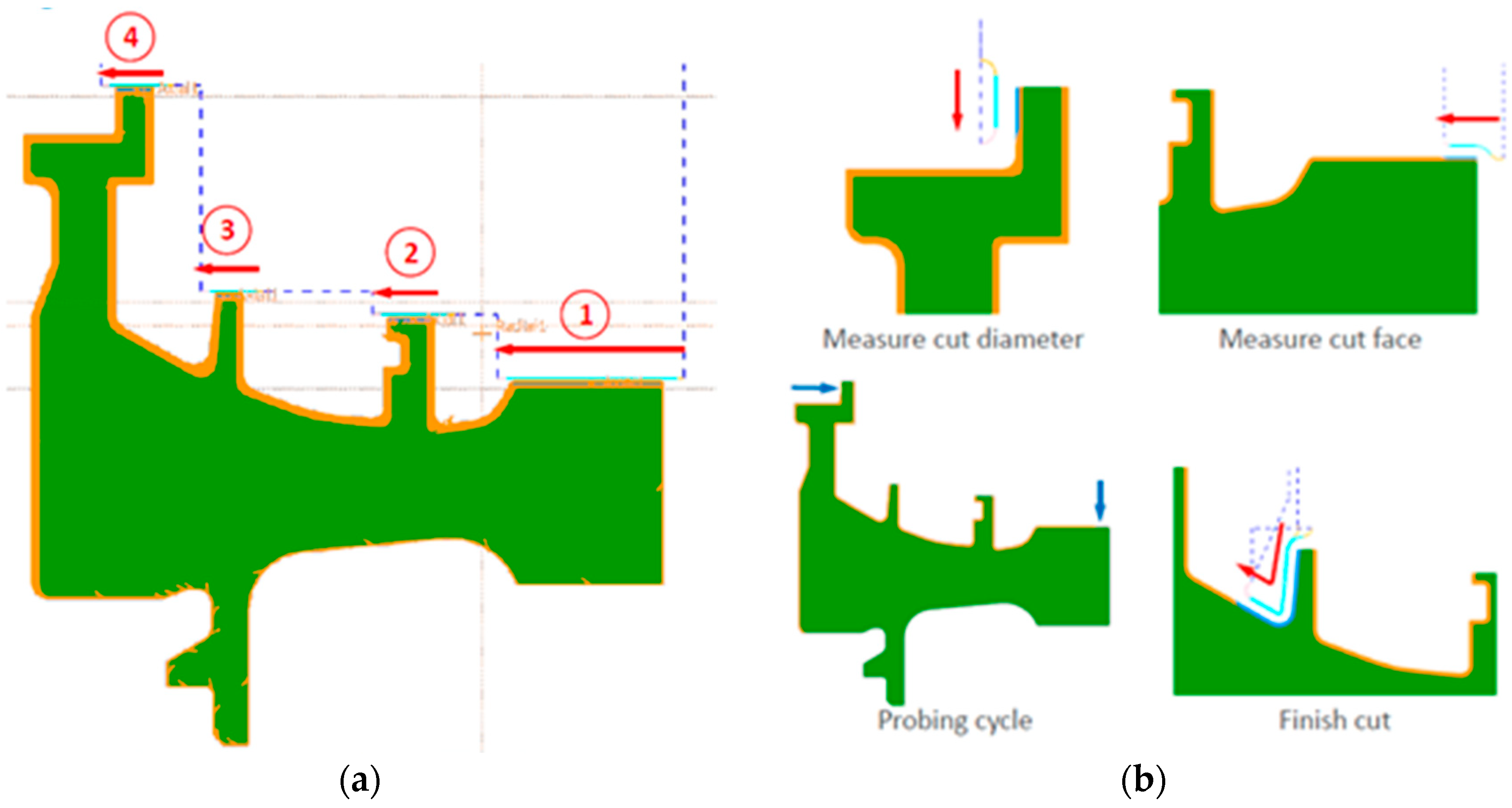
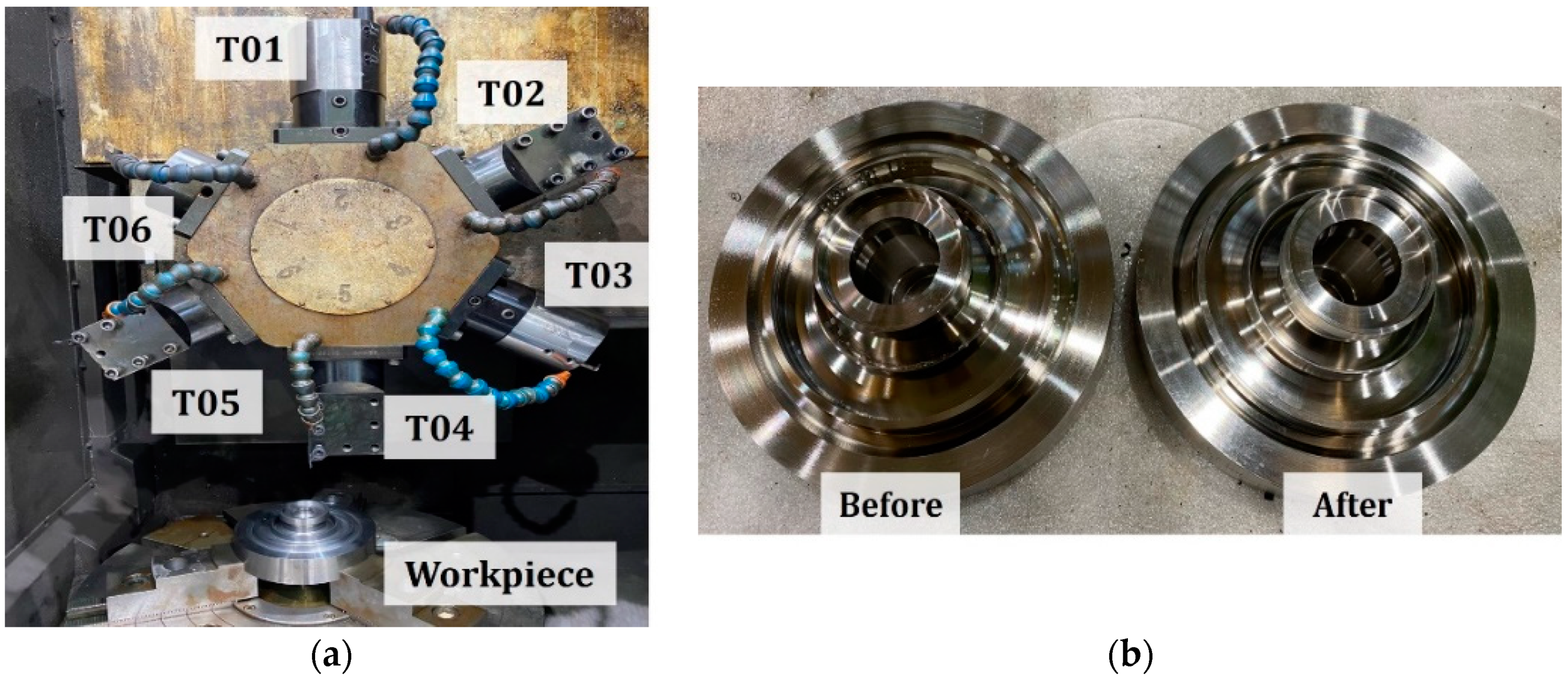
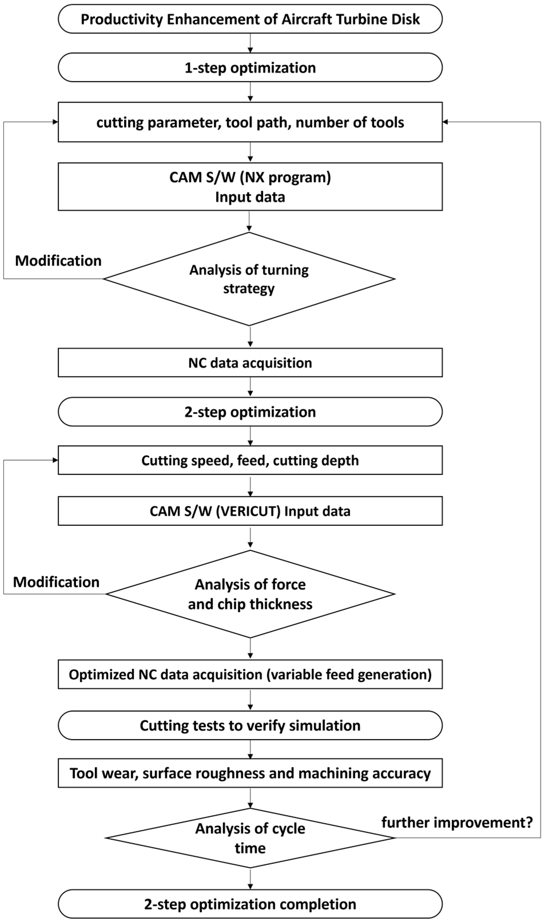
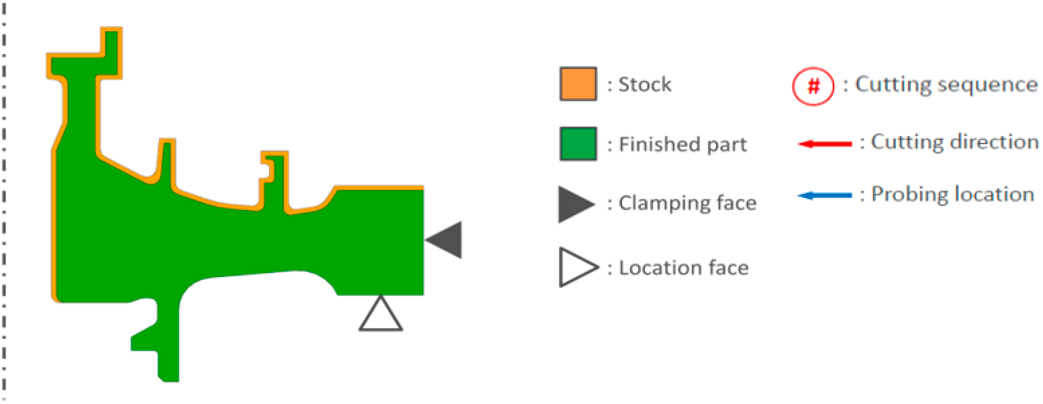
2.1. Cutting Strategy
2.2. Tool-Path Planning Using CAM Simulation
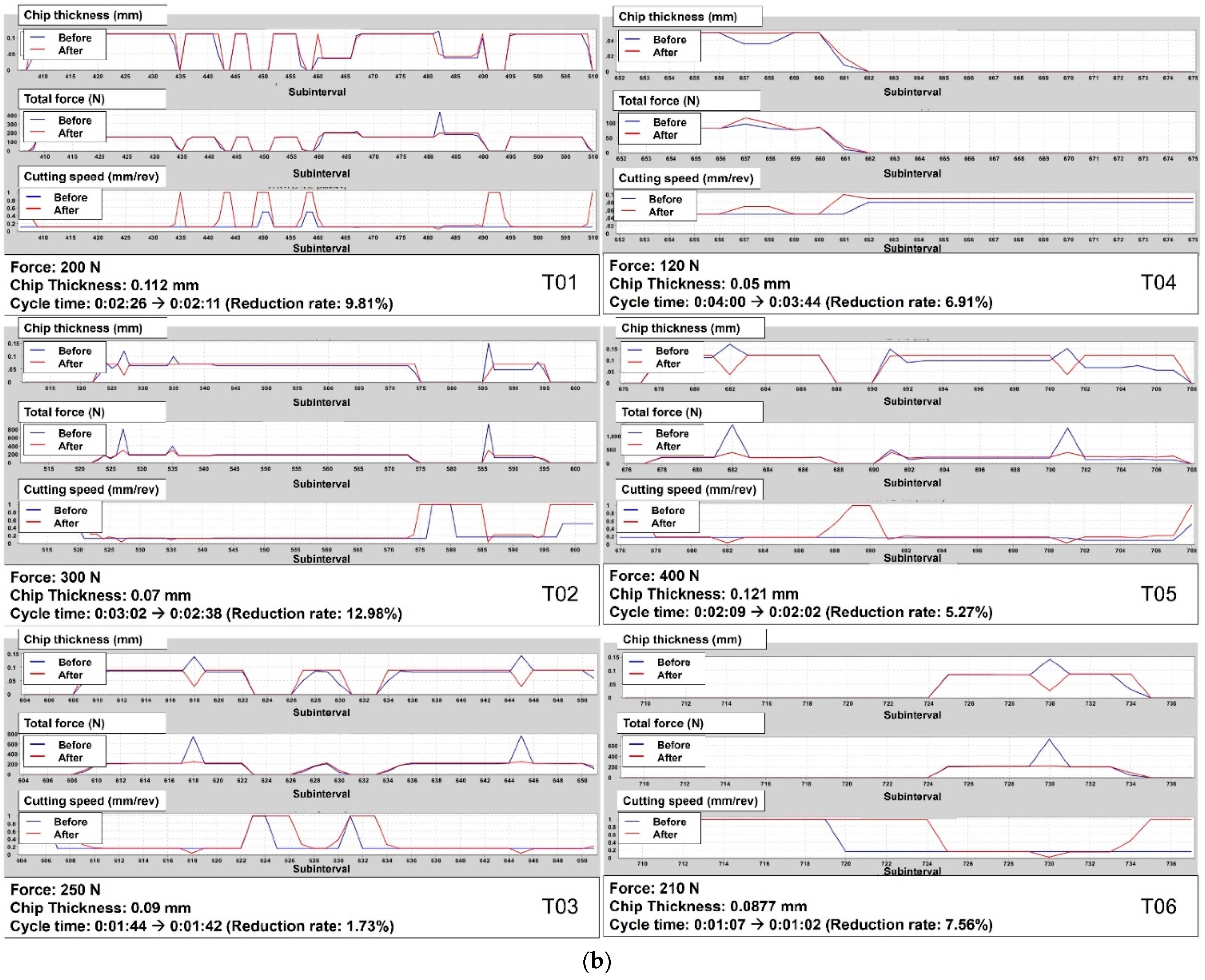
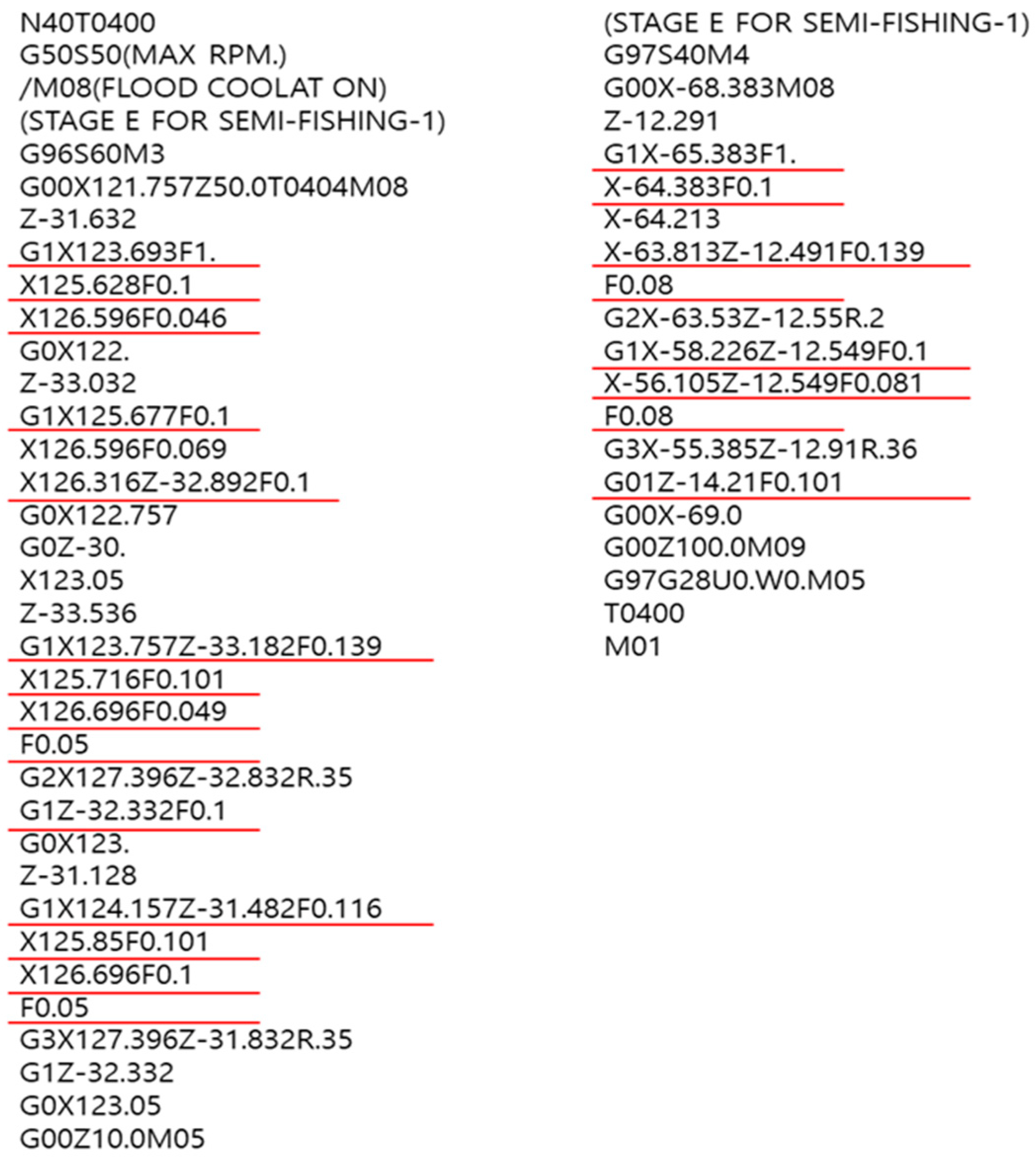
2.3. NC-Code Generation and Optimization
3. Results and Discussion
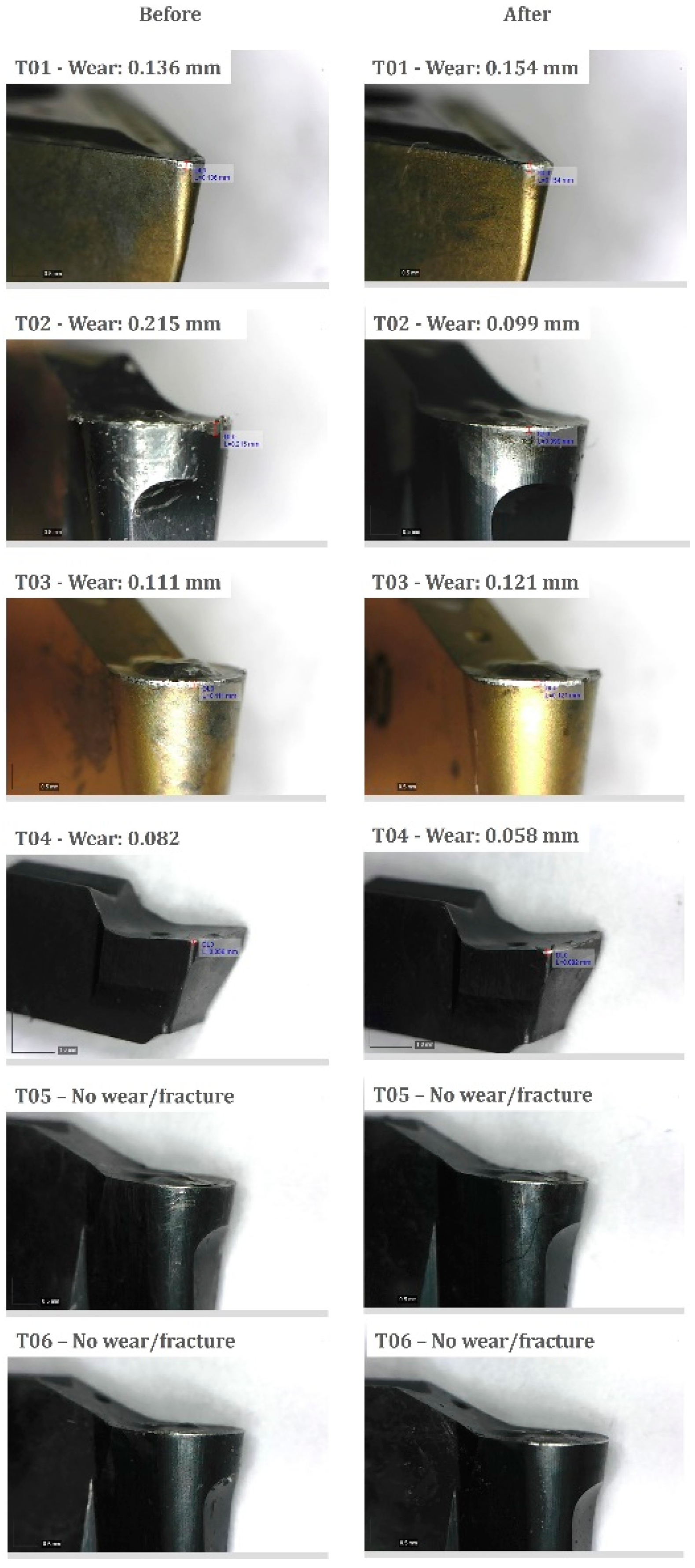
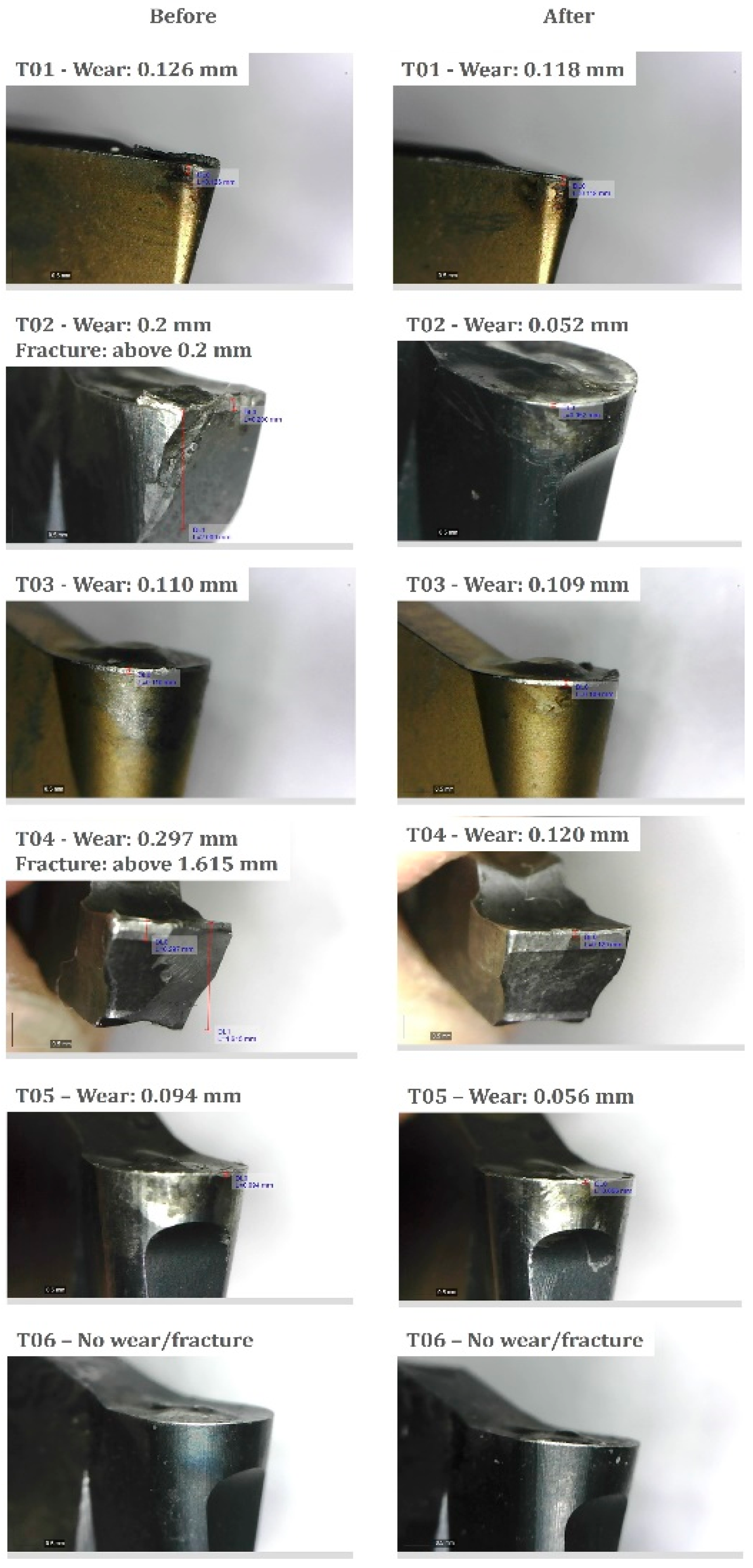
3.1. Tool Wear
3.2. Surface Roughness and Machining Accuracy
3.3. Quantitative Analysis of Cycle Time Improvement
4. Conclusions
- The number of tools was reduced from eight to six compared to the existing condition for semi-finishing and finishing of a turbine disk, and a new tool path was proposed through simulation. The cycle time was reduced by about 24%.
- NC-code optimization was performed through feed optimization considering cutting force and chip thickness. As a result, cycle times were reduced by about 14%.
- As a result of analyzing tool wear by performing a cutting test, it was confirmed that tool wear was reduced by up to 74% in semi-finishing and up to 54% in finishing. This is because machining was performed while maintaining a constant cutting force and chip thickness.
- Through tool-path optimization and NC-code optimization, it was confirmed that the total cycle time was reduced by about 54% and tool wear was significantly improved.
- The method proposed in this study dramatically enhanced productivity and reduced manufacturing cost.
Author Contributions
Funding
Institutional Review Board Statement
Informed Consent Statement
Data Availability Statement
Conflicts of Interest
References
- Gloria, A.; Montanari, R.; Richetta, M.; Varone, A. Alloys for Aeronautic Applications: State of the Art and Perspectives. Metals 2019, 9, 662. [Google Scholar] [CrossRef] [Green Version]
- Blanco, D.; Rubio, E.M.; Lorente-Pedreille, R.M.; Sáenz-Nuño, M.A. Lightweight Structural Materials in Open Access: Latest Trends. Materials 2021, 14, 6577. [Google Scholar] [CrossRef] [PubMed]
- Yan, C.; Yin, Z.; Shen, X.; Mi, D.; Guo, F.; Long, D. Surrogate-based optimization with improved support vector regression for non-circular vent hole on aero-engine turbine disk. Aerosp. Sci. Technol. 2020, 96, 105332. [Google Scholar] [CrossRef]
- Song, L.-K.; Bai, G.-C.; Li, X.-Q.; Wen, J. A unified fatigue reliability-based design optimization framework for aircraft turbine disk. Int. J. Fatigue 2021, 152, 106422. [Google Scholar] [CrossRef]
- Gonzalez, H.; Pereira, O.; de Lacalle, L.N.L.; Calleja, A.; Ayesta, I.; Muñoa, J. Flank-Milling of Integral Blade Rotors Made in Ti6Al4V Using Cryo CO2 and Minimum Quantity Lubrication. J. Manuf. Sci. Eng. 2021, 143, 091011. [Google Scholar] [CrossRef]
- Suárez, A.; Veiga, F.; de Lacalle, L.N.L.; Polvorosa, R.; Lutze, S.; Wretland, A. Effects of Ultrasonics-Assisted Face Milling on Surface Integrity and Fatigue Life of Ni-Alloy 718. J. Mater. Eng. Perform. 2016, 25, 5076–5086. [Google Scholar] [CrossRef]
- Polvorosa, R.; Suárez, A.; de Lacalle, L.N.L.; Cerrillo, I.; Wretland, A.; Veiga, F. Tool wear on nickel alloys with different coolant pressures: Comparison of Alloy 718 and Waspaloy. J. Manuf. Process. 2017, 26, 44–56. [Google Scholar] [CrossRef]
- Suárez, A.; Veiga, F.; de Lacalle, L.L.; Polvorosa, R.; Wretland, A. An investigation of cutting forces and tool wear in turning of Haynes 282. J. Manuf. Process. 2019, 37, 529–540. [Google Scholar] [CrossRef]
- Lin, Z.; Fu, J.; Shen, H.; Gan, W.; Yue, S. Tool path generation for multi-axis freeform surface finishing with the LKH TSP solver. Comput. Aided Des. 2015, 69, 51–61. [Google Scholar] [CrossRef]
- Pezer, D. Efficiency of Tool Path Optimization Using Genetic Algorithm in Relation to the Optimization Achieved with the CAM Software. Procedia Eng. 2016, 149, 374–379. [Google Scholar] [CrossRef] [Green Version]
- Ridwan, F.; Xu, X.; Ho, F.C.L. Adaptive execution of an NC program with feed rate optimization. Int. J. Adv. Manuf. Technol. 2012, 63, 1117–1130. [Google Scholar] [CrossRef]
- Xu, G.; Chen, J.; Zhou, H.; Yang, J.; Hu, P.; Dai, W. Multi-objective feedrate optimization method of end milling using the internal data of the CNC system. Int. J. Adv. Manuf. Technol. 2019, 101, 715–731. [Google Scholar] [CrossRef]
- Hatem, N.; Yusof, Y.; Kadir, A.Z.A.; Latif, K.; Abedlhafd, M.M. Optimization and execution of multiple holes-drilling operations based on STEP-NC. Int. J. Adv. Manuf. Technol. 2021, 114, 2031–2043. [Google Scholar] [CrossRef]
- Lukic, D.; Cep, R.; Vukman, J.; Antic, A.; Djurdjev, M.; Milosevic, M. Multi-Criteria Selection of the Optimal Parameters for High-Speed Machining of Aluminum Alloy Al7075 Thin-Walled Parts. Metals 2020, 10, 1570. [Google Scholar] [CrossRef]
- Hu, D.; Guo, J. Tool path optimization algorithm of spatial cam flank milling based on NURBS surface. J. Braz. Soc. Mech. Sci. Eng. 2018, 40, 170. [Google Scholar] [CrossRef]
- Dittrich, M.-A.; Uhlich, F.; Denkena, B. Self-optimizing tool path generation for 5-axis machining processes. CIRP J. Manuf. Sci. Technol. 2019, 24, 49–54. [Google Scholar] [CrossRef]
- Hatem, N.; Yusof, Y.; Kadir, A.Z.A.; Latif, K.; Mohammed, M. A novel integrating between tool path optimization using an ACO algorithm and interpreter for open architecture CNC system. Expert Syst. Appl. 2021, 178, 114988. [Google Scholar] [CrossRef]
- Han, Z.; Jin, H.; Fu, Y.; Fu, H. Cutting deflection control of the blade based on real-time feedrate scheduling in open modular architecture CNC system. Int. J. Adv. Manuf. Technol. 2017, 90, 2567–2579. [Google Scholar] [CrossRef]
- Liang, F.; Yan, G.; Fang, F. Global time-optimal B-spline feedrate scheduling for a two-turret multi-axis NC machine tool based on optimization with genetic algorithm. Robot. Comput. Integr. Manuf. 2022, 75, 102308. [Google Scholar] [CrossRef]
- Park, H.S.; Qi, B.; Dang, D.-V.; Park, D.Y. Development of smart machining system for optimizing feedrates to minimize machining time. J. Comput. Des. Eng. 2018, 5, 299–304. [Google Scholar] [CrossRef]


| Parameters | Specification |
|---|---|
| Material | Waspaloy |
| Cycle time | 58 min 24 s |
| Cutting tool inserts (No.: Product model) | T01: CNMG120408 T02: VBMT160404 T03: VDB125RA T04: VDX009-B-03 T05: CCMT09T308FG T06: VDB005-A-R04 T07: VDX009-B-01 T08: GIP-3.00E-0.4 |
| Platform information for machining | Vertical lathe with Fanuc controller |
| No. | Insert | Nose Radius |
|---|---|---|
| T01 | DNMG150408 | 0.8 mm |
| T02 | N123F2-0300-RO | 1.5 mm |
| T03 | N123F2-0300-RO | 1.5 mm |
| T04 | N123G2-0300-0004-GF | 0.4 mm |
| T05 | N123H1-0200-RO (L) | 1.0 mm |
| T06 | N123F2-0300-RO | 1.5 mm |
| (a) | |||||
| Stage | No. of Tool | (m/min) | (mm/rev) | (mm) | Time (mm:ss) |
| A | T01 | 60 | 0.15 | 0.5 | 02:24 |
| B | T02 | 50 | 0.08 | 0.5 | 02:37 |
| C | T03 | 50 | 0.15 | 0.5 | 01:24 |
| D | T04 | 55 | 0.15 | 0.5 | 02:50 |
| E | T05 | 50 | 0.15 | 0.5 | 04:05 |
| F | T03 | 50 | 0.15 | 0.5 | 00:30 |
| G | T01 | 60 | 0.15 | 0.5 | 01:08 |
| H | T06 | 55 | 0.15 | 0.5 | 00:37 |
| (b) | |||||
| Stage | No. of Tool | (m/min) | (mm/rev) | (mm) | Time (mm:ss) |
| I | T01 | 65 | 0.12 | 0.25 | 01:52 |
| J | T03 | 50 | 0.12 | 0.25 | 02:49 |
| K | T04 | 55 | 0.12 | 0.25 | 06:27 |
| L | T02 | 50 | 0.08 | 0.25 | 03:05 |
| M | T05 | 50 | 0.12 | 0.25 | 07:53 |
| N | T03 | 50 | 0.12 | 0.25 | 00:56 |
| O | T06 | 55 | 0.12 | 0.25 | 01:35 |
| P | T01 | 65 | 0.12 | 0.25 | 02:22 |
| Q | T01 | 65 | 0.12 | 0.25 | 02:04 |
| No. | Cutting Tool Insert | Tool Holder | |
|---|---|---|---|
| Before | After | ||
| T01 | DNMG150408 | DCMT32.51 MT TT5080 (TaeguTec, Daegu, Korea) | S25R-SDQCL-11 |
| T02 | N123F2-0300-RO | N123F2-0300-RO (SANDVIK, Stockholm, Sweden) | RG123G07-2525C |
| T03 | N123F2-0300-RO | TDT 3E-1.5-RU (TaeguTec, Daegu, Korea) | TTFR25-70-3RN |
| T04 | N123G2-0300-0004-GF | GEDI 3.00-0.20 (ISCAR, Migdal, Israel) | GEHIR 12-15-3-T6 |
| T05 | N123H1-0200-RO (L) | N123H1-0200-RO (L) (SANDVIK, Stockholm, Sweden) | RF123F10-2525B |
| T06 | N123F2-0300-RO | N123F2-0300-RO (SANDVIK, Stockholm, Sweden) | TGEUL2525-3S |
| Roughness Parameters | Surface Roughness (μm) | |
|---|---|---|
| Before Optimization | After Optimization | |
| 0.806 | 0.869 | |
| 3.827 | 3.167 | |
| 4.401 | 4.782 | |
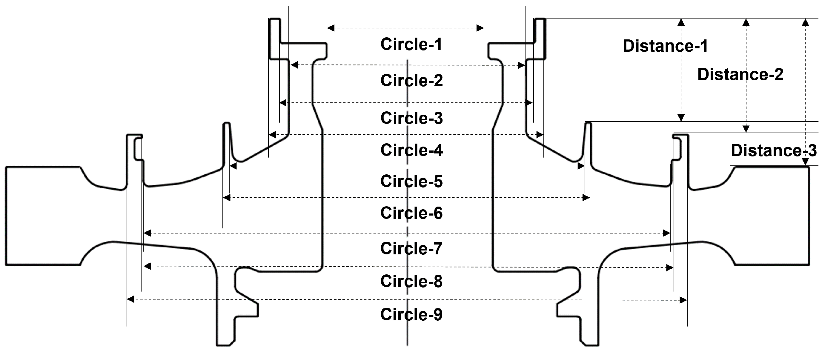
| Measuring Items | Specification (mm) | Measurement Value (mm) | |
|---|---|---|---|
| Before Optimization | After Optimization | ||
| Circle-1 | 37.900 ± 0.2 | 38.002 | 38.010 |
| Circle-2 | 55.560 ± 0.2 | 55.519 | 55.671 |
| Circle-3 | 59.700 ± 0.2 | 59.641 | 59.648 |
| Circle-4 | 64.500 ± 0.2 | 64.690 | 64.485 |
| Circle-5 | 83.300 ± 0.2 | 82.390 | 83.454 |
| Circle-6 | 85.940 ± 0.2 | 86.074 | 86.096 |
| Circle-7 | 123.760 ± 0.2 | 123.808 | 123.782 |
| Circle-8 | 124.400 ± 0.2 | 124.225 | 124.269 |
| Circle-9 | 131.500 ± 0.2 | 131.678 | 131.832 |
| Distance-1 | 24.630 ± 0.2 | 24.619 | 24.622 |
| Distance-2 | 27.430 ± 0.2 | 27.415 | 27.420 |
| Distance-3 | 35.050 ± 0.2 | 35.063 | 35.042 |
| Order | Progress | Cycle Time (mm:ss) | Improvement Rate | |
|---|---|---|---|---|
| Before | After | |||
| 1 | No. of tools reduction and tool-path optimization | 58:24 (Machine cycle time) | 44:40 (NX environment) | 24% |
| 2 | NC-code optimization with variable feed | 30:58 (Vericut environment; same environment as machine cycle time) | 26:34 (Machine cycle time) | 14% |
| Total of cycle time | 58:24 | 26:34 | 54% | |
Publisher’s Note: MDPI stays neutral with regard to jurisdictional claims in published maps and institutional affiliations. |
© 2022 by the authors. Licensee MDPI, Basel, Switzerland. This article is an open access article distributed under the terms and conditions of the Creative Commons Attribution (CC BY) license (https://creativecommons.org/licenses/by/4.0/).
Share and Cite
Woo, W.-S.; Curtis, D.; Bagni, C.; Lee, C.-M.; Lee, J.-H.; Kim, D.-H. Productivity Enhancement of Aircraft Turbine Disk Using a Two-Step Strategy Based on Tool-Path Planning and NC-Code Optimization. Metals 2022, 12, 567. https://doi.org/10.3390/met12040567
Woo W-S, Curtis D, Bagni C, Lee C-M, Lee J-H, Kim D-H. Productivity Enhancement of Aircraft Turbine Disk Using a Two-Step Strategy Based on Tool-Path Planning and NC-Code Optimization. Metals. 2022; 12(4):567. https://doi.org/10.3390/met12040567
Chicago/Turabian StyleWoo, Wan-Sik, David Curtis, Cristian Bagni, Choon-Man Lee, Joung-Hwan Lee, and Dong-Hyeon Kim. 2022. "Productivity Enhancement of Aircraft Turbine Disk Using a Two-Step Strategy Based on Tool-Path Planning and NC-Code Optimization" Metals 12, no. 4: 567. https://doi.org/10.3390/met12040567
APA StyleWoo, W.-S., Curtis, D., Bagni, C., Lee, C.-M., Lee, J.-H., & Kim, D.-H. (2022). Productivity Enhancement of Aircraft Turbine Disk Using a Two-Step Strategy Based on Tool-Path Planning and NC-Code Optimization. Metals, 12(4), 567. https://doi.org/10.3390/met12040567