Abstract
In this paper, the high temperature deformation behaviour of 17-4PH steel was studied. A new forming optimization method was proposed. The study will help guide the obtainment of high-precision and high-mechanical properties forging products in the aerospace industry. A hot compression test was carried out on a Gleeble1500D test machine (DUFFERS SCIENTFIC, Beijing, China). The stress–strain behaviour at a temperature of 1000 °C~1150 °C and strain rate of 0.1~10 s−1 was analysed. Through the analysis of multiple heating tests, we come to the conclusion that the heating times should be controlled within 1 or 2 times in order to obtain a grain size above grade 6. Optimization analysis of the forming process was carried out to shorten the process and ensure the precision of the product. The preform shape was obtained quickly by fourth-order curve fitting. According to the method of finite element numerical simulation, the near net forming process within two heating procedures was determined. A 17-4PH forging product with precise shape and qualified structure was obtained through actual forming test.
1. Introduction
Net shape forging is a modern manufacturing process that considers environmental impact and resource efficiency comprehensively on the premise of ensuring the function, quality, and cost of products [1,2,3]. Net shape forging demonstrates many advantages such as minimum material waste, high dimensional accuracy, reduction or complete elimination of machining, good surface finish, and better mechanical properties of products [4,5]. It has become the development trend for the forging industry [6]. Net shape forging can be divided into hot precision forging and warm precision forging [7,8,9]. Surface oxidation usually occurs during hot precision forging due to high temperature. The product dimensional accuracy and surface quality is reduced. So, a certain amount of machining allowance is retained for hot precision forging. Aerospace forgings are mostly multi-variety and small-batch products, which are often machined into the required shape directly. For high performance forgings with batch requirements, near net forming technology has become an economical advanced manufacturing process [10].
The parts of a rocket motor are usually made of 38Cr2Mo2VA high-strength steel after free forging, machining, and chromium plating forming processes. The disadvantages of this steel are long processing flow, low material utilization rate, unstable electroplating quality, environmental pollution, and high comprehensive cost. Due to the high specific strength, toughness, and good corrosion resistance, 17-4PH steel is widely used in the field of aerospace as a replacement material [11]. 17-4 PH steel is a kind of precipitation hardening stainless steel [12,13]. The steel can obtain strength of about a 1100~1300 MPa level after heat treatment. The design and control of hot metal forming depend on the base material’s properties, tool/workpiece interface conditions, and product requirements [14]. On the one hand, the near net forming process can effectively avoid the disadvantages of the original post-milling electroplating production. It will help achieve a short-flow and environmentally friendly production process. On the other hand, near net forming can greatly reduce the production cost. In the process of deformation, 17-4PH forging products should not only achieve control of the shape, but also be more important to control the microstructure and properties [15,16]. Trzepieciński et al. [17] investigated the forming process of 17-4PH steel at high temperature. However, the fundamental high temperature deformation behaviours were not clarified. For hot forming, such as forging or rolling, it is important to understand the high temperature deformation behaviour of the base material [18,19]. Many constitutive models have been proposed for describing the high temperature deformation behaviour of steels and other alloys. Classical Arrhenius-type constitutive equations and artificial neural network (ANN) model are both applied to predict high temperature deformation behaviour [20,21]. High temperature deformation behaviour is related to the microstructure, forming conditions, etc. [22]. To the authors’ knowledge, there are few articles concerning the high temperature deformation behaviour of 17-4PH steel.
Finite element simulation has been widely used as an optimization design technology in the application of forging processes [23]. Sheu et al. [24] investigated the feasibility of one-step and two-step forming processes for a coupled gear forging numerically and experimentally. They proposed a preform design method based on the geometrical features of the product. Meng et al. [25] proposed the response surface method combined with the finite element simulation and obtained optimum geometric parameters of pre-forging for the coupler knuckle of a railway wagon. Lee et al. [26] used the electric field theory for hot forging preforming design. The preform shape for axisymmetric forging was found based on the equipotential lines arranged between the initial shape and the final shape. However, this method may be only applicable to forging problems with axisymmetric or 2D planar features. Many optimization variables should be designed in forging forming processes, such as initial blank shape, forging temperature, pre-formed blank shape, forming speed, and die size. In the present work, a rapid design method of pre-form blank was proposed based on the shape characteristics of parts and numerical simulation analysis. It will help in finding a new route for the forming optimization.
In this paper, the high temperature deformation behaviour of aero-engine level 17-4PH steel was studied. A constitutive model was proposed and applied in numerical simulation. The effects of multiple heating and multi-process forging on grain size were studied. Through numerical optimization, the forming process was shortened, the product structure was changed, the mechanical properties were improved, and a reasonable process flow was proposed.
2. Experimental Materials and Procedure
Table 1 shows the chemical composition of the studied 17-4PH steel. In order to investigate the high-temperature deformation behaviour, the 17-4PH steel was subjected to a hot compression test on a Gleeble1500D test machine (DUFFERS SCIENTFIC, Beijing, China). The sample was cylinder with a diameter of 10 mm and height of 15 mm. The schematic diagram of the hot compression test is shown in Figure 1. The sample was put into the closed chamber. Argon atmosphere was created in the chamber by pumping out the air. As shown in Figure 2, the sample was heated up to the test temperature and held for 60 s before compression. The test temperatures were 1000, 1050, 1100, and 1150 °C, respectively, according to the hot forging temperature range. The strain rates were 0.1, 1, and 10 s−1, respectively, according to actual condition. The compression rate was 50%. The temperature was measured by the R-type thermocouple (Range: 0~1600 °C, Resolution: ±1 °C) and the deformation was measured by the L-gauge system of the Gleeble 1500D test machine (DUFFERS SCIENTFIC, Beijing, China).

Table 1.
Chemical composition of the studied 17-4PH steel (wt%).
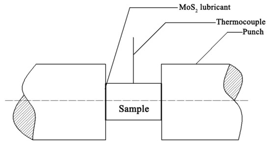
Figure 1.
Schematic diagram of the hot compression test.
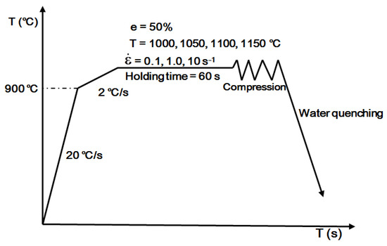
Figure 2.
Schematic diagram of the hot compression temperature–time curve.
The specimens for microstructure observation were machined from the multiple heating forging sample. The specimens were ground by sandpaper until 2000 mesh. Then the specimens were polished mechanically, and the prior austenite grain boundary was etched by picric acid aqueous solution (picric acid 100 g, deionized water 150 mL) at a water bath. The specimens were soaked in the water bath for 15 s at 60 °C. Finally, the surface was cleaned with alcohol and dried for observation. Microstructure observation was conducted by a ZEISS Imager (ZEISS, Beijing, China). M2m optical microscope (OM).
3. Results and Discussion
3.1. High-Temperature Rheological Properties of 17-4PH Steel
The high temperature stress–strain curve was obtained after data processing shown in Figure 3. The true stress–strain curves of 17-4PH steel can be divided into two types [27]: the first type, under high strain, is characterized by dynamic recovery, that is, the stress rises sharply at the initial deformation stage, and work hardening of the sample dominates. When the stress reaches a certain value, the working hardening rate and dynamic recovery rate gradually tend to balance. The stress increases with the increase in strain. The stress–strain curves under low temperature and high strain rate showed obvious dynamic recovery type. The second type is dynamic recrystallization. With the increase in strain, the real flow stress rises rapidly at the beginning, and then the increase rate becomes slow. When the stress reaches a maximum value, the stress decreases and finally the stress–strain curve comes into a plateau stage with the increase in strain. A critical strain exists, and the peak stress is obvious. The higher the temperature is, the more obvious dynamic recrystallization characteristics of the curve occur.
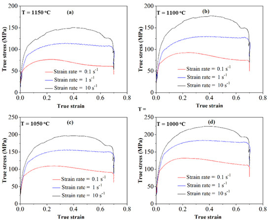
Figure 3.
True stress–strain curves of 17-4PH steel at different temperatures and strain rates. (a) 1150 °C; (b) 1100 °C; (c) 1050 °C; (d) 1000 °C.
The modelling of hot deformation behaviour and the prediction of flow curves are important in metal forming processes because numerical simulation needs accurate flow description [28,29]. The most widely applied method for analysing high-temperature rheological behaviour in the literature is the model of flow stress using an expression which is related to the Zener-Hollomon parameter [30]. The stress–strain curve of hot deformation is determined by thermodynamic conditions such as , , and T [31]. For most metals, the constitutive equation of hot deformation can be expressed as a general equation:
where, is flow stress, is strain, is strain rate (s−1), and T is temperature (°C). x is the chemical composition which is not considered as the main factor.
Modern thermodynamic theory can avoid studying the plastic deformation mechanism from the perspective of a metal energy state [32,33]. According to the irreversible thermodynamic theory, the following assumptions are made:
Considering the influence of , , and T at the same time, the model is as follows:
In the above formula, A, B, D, a, b, c, and d are constant coefficients related to deformed material, deformation temperature, and strain rate. Figure 4 shows regression curves drawn according to Equations (2)–(4) under given conditions.
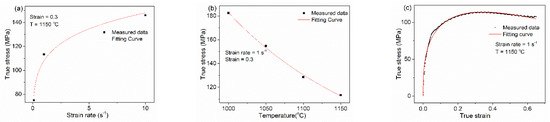
Figure 4.
Regression results of the flow stress with different parameters. (a) Strain rate; (b) temperature; (c) strain.
According to Equation (5), nonlinear regression was carried out on experimental data, and we obtained:
The mathematical model well reflected the deformation law and stress–strain characteristics of the steel and provided accurate material data for the later simulation. The present model is simple and practical for the simulation as compared with artificial neural network (ANN) based models or convolutional neural network (CNN) based models, which is complex to find an interface between the model and simulation process [34].
3.2. Effects of Multiple Heating Forges on Grain Size
17-4PH steel is usually subjected to a two-step heat treatment to achieve the properties requirements for products [35]. Firstly, a solution treatment at sufficiently high temperature is required to achieve the maximum solid solution of alloying elements [36]. The undesirable grain growth should be avoided at the same time. After soaking at the solid solution temperature, the steel is cooled down to room temperature by air or oil. Secondly, aging treatment will be conducted to achieve high strength by precipitation hardening. The average grain size of 13.2 μm for the solution-treated steel can be refined to 2.2 μm after cyclic heat treatment. The uniform fine grains obtained after solid solution can guarantee the performance. Figure 5 shows the forging of a solid rocket motor. The volume distribution of the product is uneven, and the deformation can be only realized through multi-step deformation. According to previous studies for 17-4PH steel [37,38,39], δ-ferrite will form, and cracks will occur during the hot forming when the initial forging temperature exceeds 1200 °C. Therefore, the initial forging temperature is selected to be 1180 °C. It is reported that the ductility of 17-4 PH steel decreases in the temperature range around 900 °C, which is close to the duplex austenite + ferrite phase range [40]. Therefore, the final forging temperature should be above 950 °C. The range of forging temperature is relatively narrow. In order to satisfy the grain size index after solid solution and ensure the microstructure of the product, the grain size of multiple heating forges was analysed. The analysis was designed as follows.
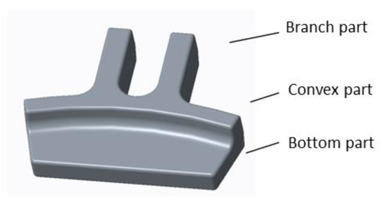
Figure 5.
Illustration of solid rocket motor forging part.
The first group: without considering the material utilization rate, a round cake shape billet with thickness of 35 mm and diameter of 200 mm was heated for one time before the final forging. After the final forging, solid solution treatment at 1040 °C and hot insulation for 1h was carried out. The microstructure after water cooling is shown in Figure 6.
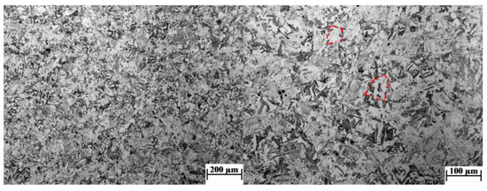
Figure 6.
Grain size of single heating process.
The second group: a billet with a diameter of 200 mm was heated for the first time and was simply pre-formed after upsetting. Then it was put into the resistance furnace for a second heating (refer to the actual production process, 30 min of hot insulation). After final forging, solid solution treatment at 1040 °C and hot insulation for 1h was carried out. The microstructure after water cooling is shown in Figure 7.
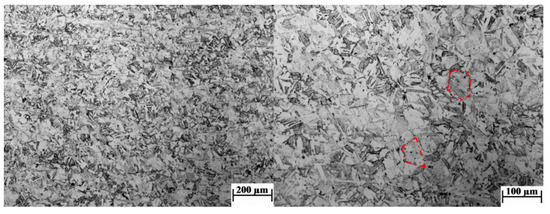
Figure 7.
Grain size of twice heating process.
The third group: a 200 mm diameter billet was heated for the first time, upsetting, drawing, and then upsetting the deformation process. It was put into the resistance furnace for a second heating (refer to the actual production process, 30 min of hot insulation), and was finally free forged and then put into the resistance furnace for a third heating (Refer to the actual production process, 30 min of hot insulation). After the final forging, solid solution treatment at 1040 °C and hot insulation for 1 h was carried out. The microstructure after water cooling is shown in Figure 8.
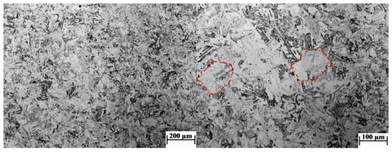
Figure 8.
Grain size of three-times heating process.
The recrystallization behaviour during the hot forming process of 17-4PH steel affected the austenite grain size evolution. For multiple heating forgings, the austenite grain size was strongly affected by the austenite coarsening during the intermediate heating process. It was determined by the temperature, deformation, strain rate, and other parameters during the final forging process. The grain size was grade 7 (average diameter: 36.7 μm) after a single heating process, shown in Figure 6, and grade 6 (average diameter: 48.3 μm) after two heating processes, shown in Figure 7. It can be seen that in single and double heating processes, the combination of process parameters in the final forging process could promote the recrystallization of austenite grains and further refine the microstructure of the forgings. However, the deformation in the final forging of three-times heated samples was too small to refine austenite grains through recrystallization. The grain size of thrice-heated forgings reached grade 3.5-4 (average diameter: 102.7 μm), shown in Figure 8, and the length of some thick martensitic lath exceeded 100 μm.
Therefore, in order to control the performance of 17-4PH solid rocket motor forgings, it is necessary to optimize the deformation step. The optimization should not only realize the short process of near net forming, but also provide reasonable process parameters for the control of the austenite grain size of forgings.
3.3. Forming Process Optimization
In actual production, there were many plate shape parts with different specifications. A rapid design method of pre-form blank was discussed based on the shape characteristics of parts and numerical simulation analysis. The parts were symmetrical, so half of them were taken for research. From the middle, a section was taken every 2 mm along the horizontal direction. The section area is shown in Figure 9 and its fourth-order fitting curve is also shown. It could be used to obtain the shape of a preformed blank quickly, and the analysis is as follows:
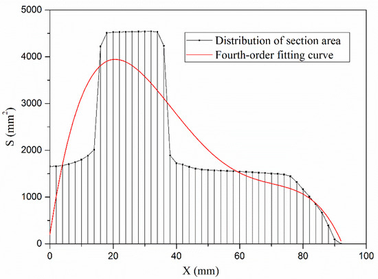
Figure 9.
Transverse distribution curve of X section area.
We defined the cross-section area function S(x), which was obtained by fitting the fourth order curve of the cross-section area:
The height function h(x) was defined as the whole value in the region which is the ratio of region volume to maximum cross-sectional area in the region. This function was expressed as:
The forging height was not complex, and could be simplified as: cross-section area S1 = 6736 mm2, as shown in Figure 10, volume V = 197,655 mm3, and have = 29.34 mm. The material utilization rate was , and the formula for calculating the deformation degree was:
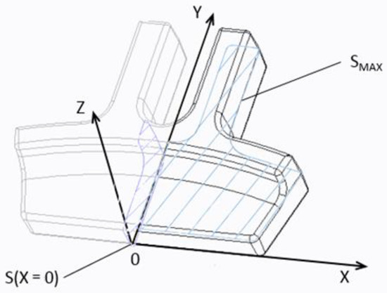
Figure 10.
Schematic diagram of cross section volume (S means section area).
The expected curve of the blank on the plane was:
If the average true strain in the component is 30%, the fourth-order fitting curve is shown in Figure 11. The area formed by this curve and the x-axis was the area of the fitting curve. We superposed the barycentre of this area and the barycentre of the 3D model to coincide with the shade formed by the Y-axis and area of the fitting curve, that was added to the upper part for volume conservation. According to the external profile of forging, the blank shape was appropriately modified. The optimized blank outline is shown in Figure 11. The numerical simulation was conducted via Deform-3D software (DUFFERS, Beijing, China). Here 40,000 grids were meshed for the pre-formed blank. Re-meshing was also proceeded automatically with the calculation. The analysis model of final forging is shown in Figure 12a. For the simulation condition, the heating temperature is set as 1050 °C and the mould temperature is 200 °C. The ram speed is 200 mm/s. The friction coefficient is 0.25 according to experience and comparison with previous paper [41]. The result of the numerical simulation is shown in Figure 12b.
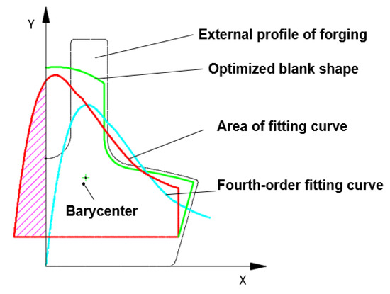
Figure 11.
Contour line optimization of pre-formed blank.
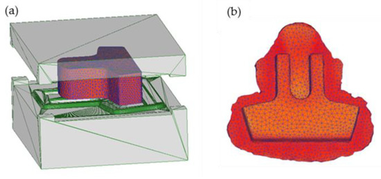
Figure 12.
Numerical simulation diagram of final forging. (a) Optimized blank outline; (b) final forging drawing after simulation.
It could be seen that the initial material distribution of the blank was very uniform, except for the U-shaped end, which caused material waste of this region. The metal extended outward first due to low minimum resistance. In terms of mould design, a blocking groove could be added to the U-shaped end to improve material utilization. Considering the filling stability of the end, this shape could be used. So, this blank design method, which combined the four-order fitting curve with the shape of blank, was scientific for the blank design of the uneven-volume distribution forgings.
After obtaining the T-shape blank, the forming of the blank was studied, as shown in Figure 13. For numerical simulation analysis of the blank of T-shaped parts, the distribution of the deformation field is shown in Figure 14a. Region B was the severe deformation area. From the beginning to the end of deformation, the metal in this area flowed continuously and strongly to both sides under a friction force since both sides were free. Region D was continuously subjected to upsetting deformation, and its wall thickness was continuously thickened. Region C was triangular in shape and had a small deformation. Therefore, the T-shaped blank presented the geometric shape shown in Figure 14b, which was more conducive to the filling of materials in the U-shaped area of the product.
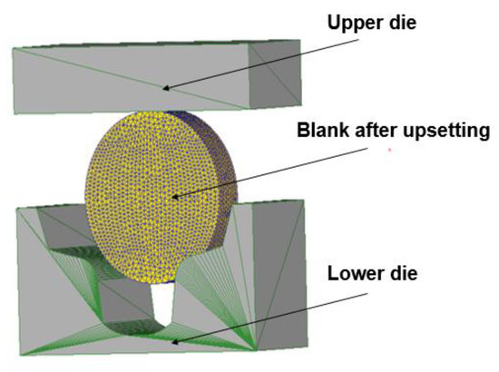
Figure 13.
Simulation analysis figure of T-shaped blank.
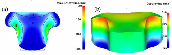
Figure 14.
Stress distribution field and displacement distribution field of T-shaped blank: (a) Stress distribution field (A, B, C, D, E refer to Compression deformation zone, Severe deformation zone, End deformation zone, Central deformation zone, Lateral deformation zone, respectively); (b) displacement distribution field.
There were many factors affecting the billet process of the T-shaped blank [42]. In order to minimize the instability factors, a graphite lubricant was used as its friction coefficient is relatively fixed. The shape and size of the lower die was fixed so that only two factors of blank diameter and thickness needed to be optimized. With relatively few analytical variables, it was easy to conclude from multiple sets of data that a billet with a diameter of 136 mm and a thickness of 35 mm should be used. The blank deformation process is shown in Figure 15. As the blank was irregular after forming (Figure 14b), the blank might be unstable in the final process. Therefore, it should be slightly flattened after the pre-formed process.
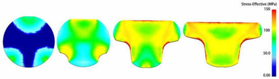
Figure 15.
Deformation process of T-shaped blank.
3.4. Forming Process Test
According to the above analysis, we determined the deformation process of round steel blanking, upsetting, pre-forging, flatting, final forging, and trimming. The high-precision box furnace with temperature control precision ±3 °C was used as heating equipment, the 400T punch machine (J31-4000KN, Beijing Research Institute of Mechanical & Electrical Technology Ltd., Beijing, China) as blank making equipment, the 3T forging hammer (C88K-50, Beijing Research Institute of Mechanical & Electrical Technology Ltd., Beijing, China) as final forging equipment, and the 400T punch press as trimming equipment (Beijing Research Institute of Mechanical & Electrical Technology Ltd., Beijing, China). 17-4PH round billet (Beijing Research Institute of Mechanical & Electrical Technology Ltd., Beijing, China) with a diameter of 100 mm and length of 65 mm was put into the furnace. The initial forging temperature was 1180 °C. The billet was subjected to upsetting deformation and the size after upsetting was a round cake with a diameter of 136 mm and length of 35mm. Then T-shaped blank was obtained after pre-forging. The forging process was completed within two rounds of heating and two steps of forging. After the first heating, upsetting and pre-forging were completed, as shown in Figure 16a. After the second heating, flatting, final forging (Figure 16b), and edge cutting (Figure 16c) were completed. The final forging temperature was 950 °C. The actual test-formed forgings not only met the requirements of microstructure, but the material utilization rate was also greatly improved. High-performance near net forming of 17-4PH steel was realized.
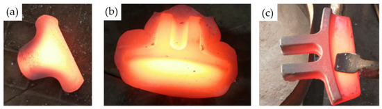
Figure 16.
Hot forging product during forming process. (a) T-shaped blank; (b) product after final forging; (c) forgings after trimming.
4. Conclusions
In this paper, the high temperature deformation behaviour of 17-4PH steel was studied. A new forming optimization method was proposed. This study could help guide the obtainment of high-precision- and high-mechanical properties in forging products in the aerospace industry. The following conclusions were drawn.
- (1)
- High-temperature rheological properties of 17-4PH steel were analysed to guide the high-precision forgings in aerospace engines. Based on the data analysis, a constitutive equation was established by a dynamic recrystallization stress–strain model, and the result was applied to the numerical simulation of the forming process.
- (2)
- The grain size of forgings after single heating or double heating was above grade 6, and was 3.5–4 after three rounds of heating.
- (3)
- A preformed blank was obtained quickly by using fourth-order curve fitting. Numerical simulation was used to determine the short flow forming process within twice-heating. We obtained forgings with precise shape and qualified microstructure through shortened forming process.
Author Contributions
Conceptualization, Y.W. and J.H.; methodology, Y.G. and Y.W.; software, Z.W.; validation, C.X., Y.W.; formal analysis, Y.G.; investigation, Y.G.; resources, Y.W. and J.H; data curation, Y.G.; writing—original draft preparation, Y.G.; writing—review and editing, Y.W. and Z.W.; visualization, Y.G. All authors have read and agreed to the published version of the manuscript.
Funding
This research received no external funding.
Institutional Review Board Statement
Not applicable.
Informed Consent Statement
Not applicable.
Data Availability Statement
The data that support the findings of this study are available from the corresponding author upon reasonable request.
Conflicts of Interest
The authors declare no conflict of interest.
References
- Yang, C.; Zhao, S.; Zhang, J. A single stage hot forging process and die set of alternator poles. Int. J. Mater. Form. 2012, 6, 511–517. [Google Scholar] [CrossRef]
- Gao, P.F.; Fei, M.Y.; Yan, X.G.; Wang, S.B.; Li, Y.K.; Xing, L.; Wei, K.; Zhan, M.; Zhou, Z.T.; Keyim, Z. Prediction of the folding defect in die forging: A versatile approach for three typical types of folding defects. J. Manuf. Process. 2019, 39, 181–191. [Google Scholar] [CrossRef]
- Behrens, B.-A.; Chugreeva, A.; Diefenbach, J.; Kahra, C.; Herbst, S.; Nürnberger, F.; Maier, H.J. Microstructural Evolution and Mechanical Properties of Hybrid Bevel Gears Manufactured by Tailored Forming. Metals 2020, 10, 1365. [Google Scholar] [CrossRef]
- Kanani, J.B.; Lalwani, D. An experimental and FEA investigation of near-net-shape cold forging of spur gear. Mater. Today Proc. 2021, 44, 92–98. [Google Scholar] [CrossRef]
- Pruncu, C.I.; Hopper, C.; Hooper, P.A.; Tan, Z.; Zhu, H.; Lin, J.; Jiang, J. Study of the Effects of Hot Forging on the Additively Manufactured Stainless Steel Preforms. J. Manuf. Process. 2020, 57, 668–676. [Google Scholar] [CrossRef]
- Rajput, S.P.S.; Datta, S. Sustainable and green manufacturing—A narrative literature review. Mater. Today Proc. 2020, 26, 2515–2520. [Google Scholar] [CrossRef]
- Mohammadi, M.; Sadeghi, M. Near Net Shape Forging of CV Joint Outer Race. Adv. Mater. Res. 2009, 83–86, 143–149. [Google Scholar] [CrossRef]
- Lu, B.; Ou, H.; Armstrong, C.; Rennie, A. 3D die shape optimisation for net-shape forging of aerofoil blades. Mater. Des. 2009, 30, 2490–2500. [Google Scholar] [CrossRef]
- Cai, J.; Dean, T.; Hu, Z. Alternative die designs in net-shape forging of gears. J. Mater. Process. Technol. 2004, 150, 48–55. [Google Scholar] [CrossRef]
- Kumar, A.; Balaji, Y.; Prasad, N.E.; Gouda, G.; Tamilmani, K. Indigenous development and airworthiness certification of 15-5 PH pre-cipitation hardenable stainless steel for aircraft applications. Sadhana 2013, 38, 3–23. [Google Scholar] [CrossRef]
- Shi, Q.; Qin, F.; Li, K.; Liu, X.; Zhou, G. Effect of hot isostatic pressing on the microstructure and mechanical properties of 17-4PH stainless steel parts fabricated by selective laser melting. Mater. Sci. Eng. A 2021, 810, 141035. [Google Scholar] [CrossRef]
- Yu, Z.; Chai, Z.; Xu, J.; Chen, J.; Chen, J.; Yu, C.; Lu, H. Achieving high strength and ductility in 17-4 PH steel with a periodic layer structure by laser direct metal depositing and aging. Mater. Sci. Eng. A 2021, 824, 141787. [Google Scholar] [CrossRef]
- Sathyanath, A.; Meena, A. Microstructural evolution and strain hardening behavior of heat-treated 17-4 PH stainless steel. Mater. Today Commun. 2020, 25, 101416. [Google Scholar] [CrossRef]
- Derazkola, H.; Gil, E.G.; Murillo-Marrodán, A.; Méresse, D. Review on Dynamic Recrystallization of Martensitic Stainless Steels during Hot Deformation: Part I—Experimental Study. Metals 2021, 11, 572. [Google Scholar] [CrossRef]
- Adomako, N.K.; Kim, S.; Yoon, J.; Lee, S.-H.; Kim, J. Finite Element Modeling of Residual Stress at Joint Interface of Titanium Alloy and 17-4PH Stainless Steel. Metals 2021, 11, 629. [Google Scholar] [CrossRef]
- Tian, J.L.; Wang, W.; Yan, W. Microstructure characteristics of segregation zone in 17-4PH stainless steel piston rod. J. Iron Steel Res. Int. 2017, 21, 718–723. [Google Scholar] [CrossRef]
- Trzepieciński, T.; Pieja, T.; Malinowski, T.; Smusz, R.; Motyka, M. Investigation of 17-4PH steel microstructure and conditions of elevated temperature forming of turbine engine strut. J. Mater. Process. Technol. 2018, 252, 191–200. [Google Scholar] [CrossRef]
- Nikulin, S.; Rogachev, S.; Nikolaev, Y.A.; Vasiliev, S.; Belov, V.; Turilina, V.Y. High-temperature mechanical properties of low-carbon steel used for the manufacture of core catcher vessel. Prog. Nucl. Energy 2021, 142, 104015. [Google Scholar] [CrossRef]
- Cho, Y.; Gwon, H.; Kim, S.-J. Effects of C and N on high-temperature deformation behavior of 15Cr–15Mn–4Ni austenitic stainless steels. Mater. Sci. Eng. A 2021, 819, 141463. [Google Scholar] [CrossRef]
- Kumar, S.; Karmakar, A.; Nath, S.K. Construction of hot deformation processing maps for 9Cr-1Mo steel through con-ven-tional and ANN approach. Mater. Tod. Commun. 2021, 26, 101903. [Google Scholar] [CrossRef]
- Xiao, X.; Liu, G.; Hu, B.; Zheng, X.; Wang, L.; Chen, S.; Ullah, A. A comparative study on Arrhenius-type constitutive equations and artificial neural network model to predict high-temperature deformation behaviour in 12Cr3WV steel. Comput. Mater. Sci. 2012, 62, 227–234. [Google Scholar] [CrossRef]
- Khandelwal, S.; Basu, S.; Patra, A. A Machine Learning-based surrogate modeling framework for predicting the history-dependent deformation of dual phase microstructures. Mater. Tod. Commun. 2021, 29, 102914. [Google Scholar] [CrossRef]
- Yin, J.; Hu, R.; Shu, X. Closed-die forging process of copper alloy valve body: Finite element simulation and experiments. J. Mater. Res. Technol. 2021, 10, 1339–1347. [Google Scholar] [CrossRef]
- Sheu, J.-J.; Yu, C.-H. Preform and forging process designs based on geometrical features using 2D and 3D FEM simulations. Int. J. Adv. Manuf. Technol. 2008, 44, 244–254. [Google Scholar] [CrossRef]
- Meng, F.-X.; Cai, Z.-Y.; Chen, Q.-M. Multi-objective optimization of preforming operation in near-net shape forming of complex forging. Int. J. Adv. Manuf. Technol. 2019, 105, 4359–4371. [Google Scholar] [CrossRef]
- Lee, S.; Lee, Y.; Park, C.; Yang, D. A new method of preform design in hot forging by using electric field theory. Int. J. Mech. Sci. 2002, 44, 773–792. [Google Scholar] [CrossRef]
- Yamagata, H.; Ohuchida, Y.; Saito, N.; Otsuka, M. Dynamic recrystallization and dynamic recovery of 99.99 mass% aluminum single crystal having [112] orientation. J. Mater. Sci. Lett. 2001, 20, 1947–1951. [Google Scholar] [CrossRef]
- Su, N.; Chen, M.; Zhang, W.; Xie, L.; Tang, W. Constitutive Modeling of 17-4PH Stainless Steel Sheet at Elevated Temperature and Statistical Optimization. J. Mater. Eng. Perform. 2020, 29, 1194–1205. [Google Scholar] [CrossRef]
- Wolfgarten, M.; Rudolph, F.; Hirt, G. Analysis of process forces and geometrical correlations for open-die forging with superimposed manipulator displacements. J. Mater. Process. Technol. 2020, 276, 116408. [Google Scholar] [CrossRef]
- Mirzadeh, H.; Cabrera, J.M.; Najafizadeh, A. Modelling and Prediction of Hot Deformation Flow Curves. Metall. Mater. Trans. A 2011, 43, 108–123. [Google Scholar] [CrossRef]
- Xu, Y.S.; Liu, J.T.; Nie, M.; Li, Z.G.; Ruan, X.Y. Research and application of mathematical model of stress-strain curve in metal thermal deformation. J. Appl. Sci. 1997, 15, 379–384. [Google Scholar]
- Gao, X.; Jiang, Z.; Wei, D.; Li, H.J.; Jiao, S.H.; Xu, J.; Zhang, X.M.; Han, J.T.; Chen, D.F. Constitutive analysis for hot deformation behaviour of novel bimetal consisting of pearl-itic steel and low carbon steel. Mater. Sci. Eng. A 2014, 595, 1–9. [Google Scholar] [CrossRef]
- Maj, P.; Adamczyk-Cieslak, B.; Lewczuk, M.; Mizera, J.; Kut, S.; Mrugala, T. Formability, Microstructure and Mechanical Properties of Flow-Formed 17-4 PH Stainless Steel. J. Mater. Eng. Perform. 2018, 27, 6435–6442. [Google Scholar] [CrossRef]
- Hirsch, F.; Natkowski, E.; Kästner, M. Modeling and simulation of interface failure in metal-composite hybrids. Compos. Sci. Technol. 2021, 214, 108965. [Google Scholar] [CrossRef]
- Mukhopadhyay, S.; Das, S.; Mukhopadhyay, G.; Bhattacharyya, G.S.; Palit, P. Improving the property of a water box noz-zle made of 17-4PH steel by suitable heat treatment. Eng. Fail. Anal. 2015, 49, 137–140. [Google Scholar] [CrossRef]
- Wu, M.; Huang, Z.; Tseng, C.; Hwang, K. Microstructures, mechanical properties, and fracture behaviors of met-al-injection molded 17-4PH stainless steel. Met. Mater. Int. 2015, 21, 531–537. [Google Scholar] [CrossRef]
- You, Y.; Yan, M.; Zhang, C. Phase field simulation for grains evolution of 17-4PH steel during cyclic heat treatment. Acta Metall. Sin. (Engl. Lett.) 2013, 26, 183–187. [Google Scholar] [CrossRef][Green Version]
- Chen, P.; Cui, Z.S.; Chen, F. Grain growth and δ-ferrite precipitation condition in 17-4PH steel during heating process. J. Plast. Eng. 2018, 25, 223–228. [Google Scholar]
- Zheng, Y.; Wu, Y.C. Control of δ-ferrite Content in Precipitation Hardening Stainless Steel 17-4PH. Spec. Steel 1998, 3, 36–39. [Google Scholar]
- Lara, V.H.; Fuentes, L.G.; Alvarado, O.C.; Rodriguez, A.S.; Sanchez, E.G. Hot Ductility of the 17-4 PH Stainless Steels. J. Mater. Eng. Perform. 2016, 25, 1041–1046. [Google Scholar] [CrossRef]
- Zhang, Y.Y.; Cui, Z.S. Measurement of Friction Factor in Hot Forging with Finite Element Simulation Using Upset-Extrusion Test. J. Shanghai Jiaotong Univ. 2015, 49, 1492–1496. [Google Scholar]
- Zhang, Q.; Felder, E.; Bruschi, S. Evaluation of friction condition in cold forging by using T-shape compression test. J. Mater. Process. Technol. 2009, 209, 5720–5729. [Google Scholar] [CrossRef]
Publisher’s Note: MDPI stays neutral with regard to jurisdictional claims in published maps and institutional affiliations. |
© 2022 by the authors. Licensee MDPI, Basel, Switzerland. This article is an open access article distributed under the terms and conditions of the Creative Commons Attribution (CC BY) license (https://creativecommons.org/licenses/by/4.0/).