Article

Microstructural and Tribological Evaluation of Brake Disc Refurbishing Using Fe-Based Coating via Directed Energy Deposition

by
Hossein Rajaei
1,
Cinzia Menapace
1,*,
Sasan Amirabdollahian
1,
Matteo Perini
2,
Giovanni Straffelini
1 and
Stefano Gialanella
1
1
Department of Industrial Engineering, University of Trento, Via Sommarive 9, 38123 Trento, Italy
2
ProM Facility, Trentino Sviluppo S.p.A., Via Fortunato Zeni, 8, 38068 Rovereto, Italy
*
Author to whom correspondence should be addressed.
Metals 2022, 12(3), 465; https://doi.org/10.3390/met12030465
Submission received: 31 January 2022 / Revised: 8 March 2022 / Accepted: 8 March 2022 / Published: 10 March 2022
(This article belongs to the Special Issue New Developments in Friction Brake Materials)

Abstract

:
In this paper, the refurbishing of worn-out brake discs by coating with powder via direct energy deposition (DED) is evaluated. A medium carbon steel powder was used to coat cast-iron discs. Deposition of this steel was carried out directly on the disc surface or, alternatively, after a previous deposition of a buffer layer made of stainless steel. It was seen that the use of a buffer layer ensured a good coating adhesion, despite the formation of cast microstructures at the interfaces between the disc and the two different coatings (buffer and outer layer). Coated discs were tested against two different Cu-free commercial friction materials to evaluate their tribological properties. Very similar friction coefficients, specific wear rates, and total emissions were measured for both friction materials sliding against the coated disc. These tribological data are slightly higher with respect to those obtained in the case of an uncoated disc, suggesting that improvement of the top coating composition and surface finishing is necessary in order to achieve better performances.

1. Introduction

Due to its low cost of manufacture, good castability, and excellent tribological and mechanical qualities, gray cast iron (GCI) is a popular casting material, widely employed in mass production, including the manufacturing of brake discs [1,2]. Exhaust brake rotors are currently managed mostly through remelting, with just a small percentage ending up in landfills. Both methods dissipate a significant amount of energy, with a significant associated CO2 footprint [3]. Another important environmental issue with disc brakes is the formation of airborne wear particles that contribute to particulate matter (PM) emissions. As regulations and exhaust emission standards become more and more rigorous, it is becoming more critical than ever to solve the issue of brake disc wear without compromising the materials’ braking performance. The design and deposition of an appropriate coating on the surface of GCI brake discs could be a viable solution to both of these problems [1]. Thin layers of hard metal systems—such as Cr3C2-NiCr, (WC-Co), (WC-Co-Cr), or WC–FeCrAlY sprayed by HVOF—have been developed, and are already being used in the light vehicle automobile market [4,5,6,7], even though this is not a cost-effective technique. According to a recent life-cycle assessment study, laser deposition of Fe-based coatings has a great potential for refurbishing worn-out GCI brake discs, in terms of both energy usage and environmental impact [3]. Cast iron has a relatively large amount of carbon in its composition (2.5–3.8 wt%) which, in the form of graphite particles, acts as a solid lubricant in brake disc applications. Cast iron, on the other hand, is particularly difficult to manage in the coating deposition process, and the coating quality might be poor, owing to the formation of cracks due to thermal stresses and carbide precipitation at the interface of the molten pool, because of the high carbon content in the GCI [8]. The use of a buffer layer such as, for example, a nickel-rich coating material with a low solidification temperature, could be employed to avoid hot cracking [9].
Among all coating processes, direct energy deposition (DED) is an alternative technique that can be used in restoring lost material on the surface of brake discs. In this technique, focused thermal energies such as lasers, electron beams, and plasma arcs are used to melt filler materials to be deposited onto the substrate. The success of laser deposition is based on the excellent layer-wise material bonding, which is achieved through thermal energy transfer with a shallow heat-affected zone (HAZ) [10]. Therefore, as a process for remanufacturing, the DED technique has been widely used to repair and recycle lots of products and materials [11,12,13]. This approach is promising, since it can be used not only to repair worn out brake discs, but also to deposit hard coatings on brand new brake discs in order to improve their performance and durability. The filler material selected has a significant impact on the microstructure and tribological properties of the product repaired via laser deposition remanufacturing. In a study by Lyu et al. [14], on the refurbishing of worn-out brake discs, the tribological characteristics of a laser-cladded high-chromium Fe-based coating were assessed by using three different friction materials. The results showed that the coated disc had a higher friction coefficient compared to that of the uncoated GCI. In comparison to uncoated GCI brake discs, laser-cladded Ni- and Co-based coatings strengthened with tungsten carbides have shown greater wear resistance and lower airborne particle emissions [15,16,17,18]. However, Ni, Co, W, and related compounds are notoriously critical as concerns a variety of health issues in humans, including cardiovascular problems, skin allergies, and lung fibrosis [19,20,21]. Therefore, new international regulations, issued by the European Chemicals Agency (ECHA), are expected to be implemented in the coming years so as to progressively eliminate the use of these elements in industrial production. As a result, alternative, less toxic powders for laser deposition on GCI brake discs must be investigated, since wear debris produced during the braking actions is partially emitted as airborne particles during the braking action [18]. The laser surface engineering of the Fe-based materials involves the alloying and hardening of the surface using a laser beam, for the purpose of improving the surface properties [11,22,23,24,25].
The goal of this project was to restore worn-out brake discs by means of a DED process, using a stainless steel as the buffer layer to reduce flaws and hot cracking, before adding a top layer of steel that is devoid of hazardous elements such as Co, Ni, Cu, and W. The importance of the buffer layer was highlighted, comparing the microstructural quality of the discs coated with and without a buffer layer. The performance of the new coated discs was evaluated through tribological tests against two different copper-free friction materials extracted from commercial brake pads.

2. Materials and Methods

A low-chromium steel—PLASweld Ferro55 (hereafter F55)—and a soft martensitic Cr-Mo-Ni stainless steel (AISI415) powder, both provided by Voestalpine Böhler Welding GmbH (Düsseldorf, Germany), were used as the top layer and buffer layer of the coating, respectively, to be applied on the surface of a pearlitic GCI brake disc substrate (Figure 1a). A scanning electron microscope (SEM, JEOL Ltd., Akishima, Japan) image of the F55 powder is shown in Figure 1b, in which the particle size distribution of the powder ranges between 40 and 150 µm. The elemental composition of the GCI and the two powders used for the coating are given in Table 1. A single layer of AISI415 steel was deposited onto the GCI substrate. Then, a double layer of F55 was deposited.
A LASERTEC 65 3D hybrid machine (DMG MORI AG, Bielefeld, Germany) with a 2500 W diode laser (λ = 1020 nm) and a coaxial powder nozzle was used for the coating depositions. The laser spot had a diameter of 3 mm and a focal length of 13 mm, with a top-hat beam profile. A laser power of 1400 W and scanning speed of 1200 mm/min were used in the coating process. The powder feed rate was set to 14 g/min, with argon serving as the carrier gas at 5 L/min and the shielding gas at 5.5 L/min. A Future-Tech microhardness tester (FM-310, Future Tech Corporation, Kawasaki, Japan) was used to assess the microhardness of the polished cross-section of the coatings, from the top of the surface down to the GCI substrate, at a force load of 300 g and a 10 second indentation duration. The hardness survey was performed from the surface onward to better understand the changes in the different layers, with a set of indentations spaced 0.15 mm apart from one another.
The dry sliding wear tests were carried out at room temperature using a Biceri wear rig pin-on-disc (PoD) tribometer (Biceri, Leeds, UK), in accordance with the ASTM G99 standard. The tribological properties of the top layer of the coating were evaluated using two different copper-free commercial friction materials, used for brake pad manufacturing. Their compositions, encoded as “A” and “B”, are listed in Table 2. Friction material A is composed of a mix of graphite, iron fibers, oxides (MgO, ZnO, Al2O3, and FeCr2O4), silicates (biotite and vermiculite), and sulfides (MoS2) embedded into a phenolic matrix. Friction material B is based on material A, with the addition of 25 wt% barite and a further 5% Fe fibers to improve tribological properties in substitution for Cu. For each tribotest, the total sliding distance was 14,400 m, contact pressure was 0.45 MPa, sliding speed was 2 m/s, and the test lasted 2 h. These values were chosen in order to achieve mild wear conditions [3]. The coefficient of friction was continually recorded throughout the tests, and the wear rates for both disc and pad materials were measured at the completion of each test. PoD tests were repeated three times for each combination of friction materials/disc. Weight loss, which was measured on a scale with 0.1 mg accuracy, was used to evaluate the wear rate.
The released particles were measured using an optical particle sizer (OPS) (TSI Incorporated, Shoreview, MN, USA). With a sampling frequency of 1 Hz, the OPS device measured particles in the range of 0.3 μm to 10 μm. The OPS instrument’s sample range was 0–3000 particles/cm3, with a regulated flow rate of 1 L/min during the sampling procedure.
A JEOL IT300 scanning electron microscope (JEOL Ltd., Akishima, Japan) operating at 20 keV accelerating voltage and equipped with an energy-dispersive X-ray spectroscope (EDXS, JEOL Ltd., Akishima, Japan) was used to examine the chemically etched (nital 2%) metallographic cross-sections of the worn surfaces of the pins and corresponding coated discs after the PoD test.
X-ray diffraction (XRD, GNR Analytical Instruments Group, Novara, Italy) analyses were carried out to evaluate the phase composition of the coated discs. The measurements were made with an ItalStructures IPD3000 diffractometer (GNR Analytical Instruments Group, Novara, Italy), using Co Kα radiation, and an Inel CPS120 detector (Inel, Artenay, France) that gathered the signal concurrently throughout an angular range of 5–120°.

3. Results

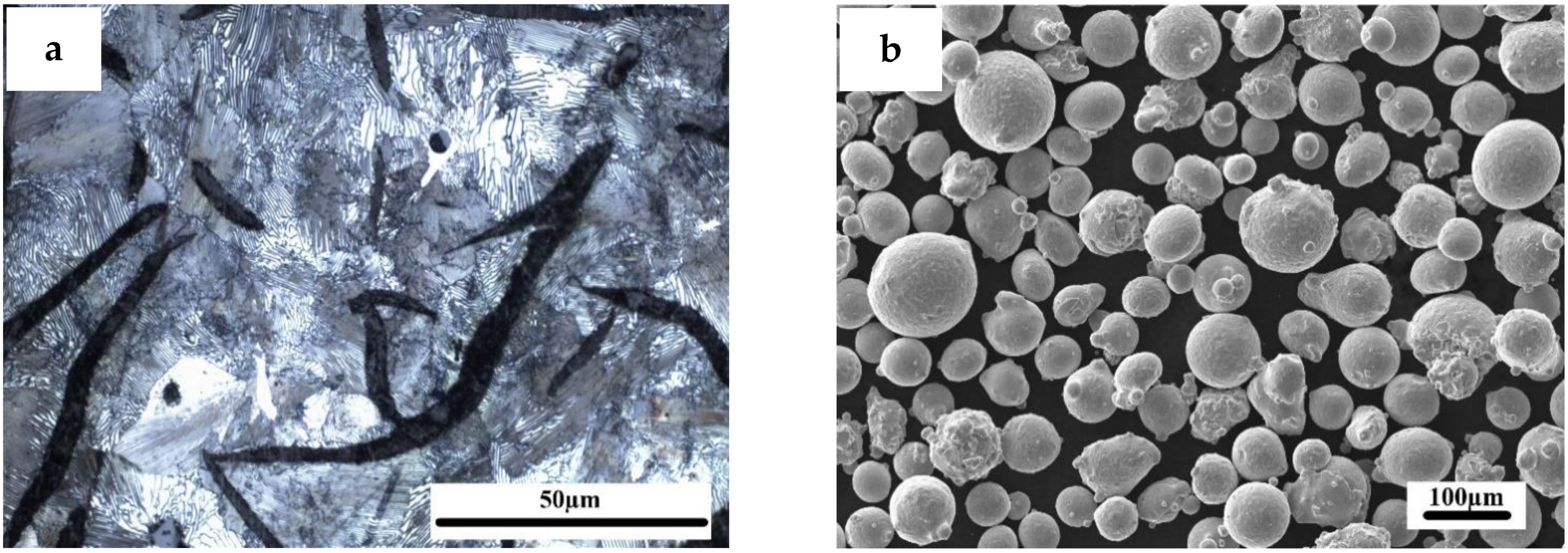
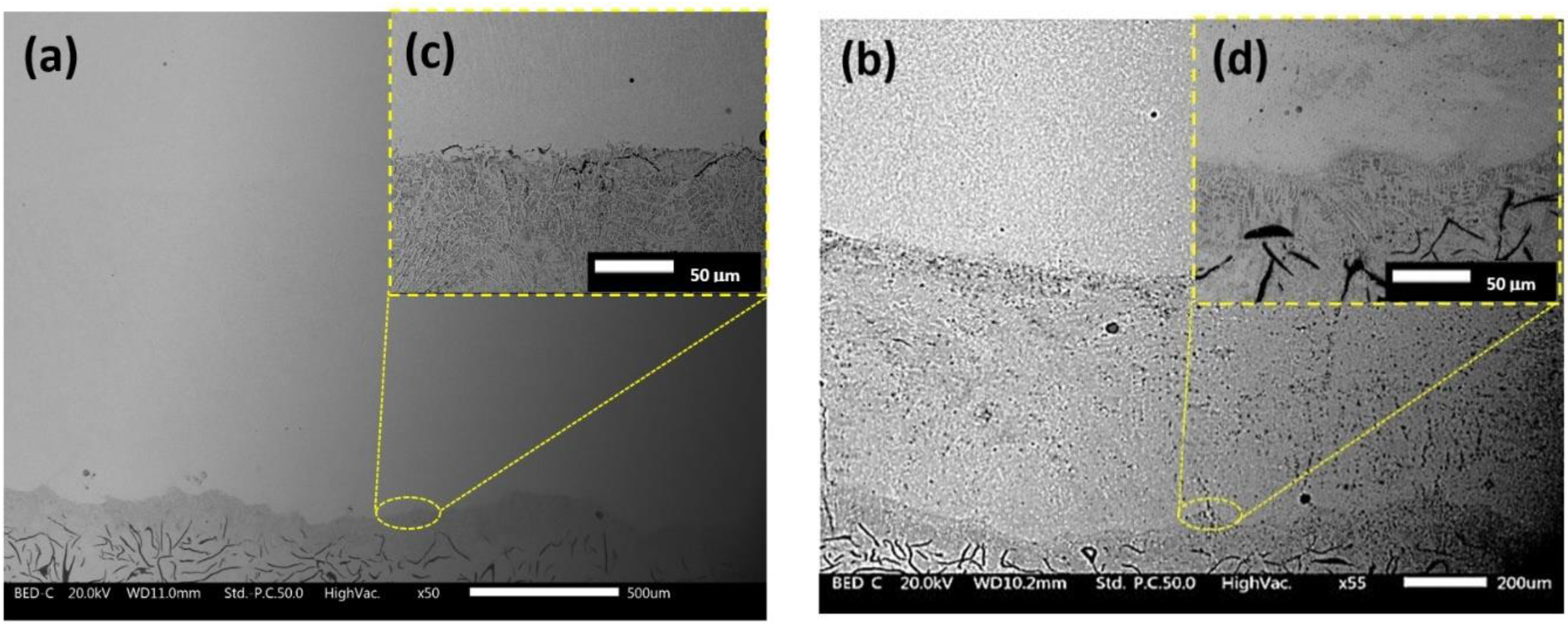
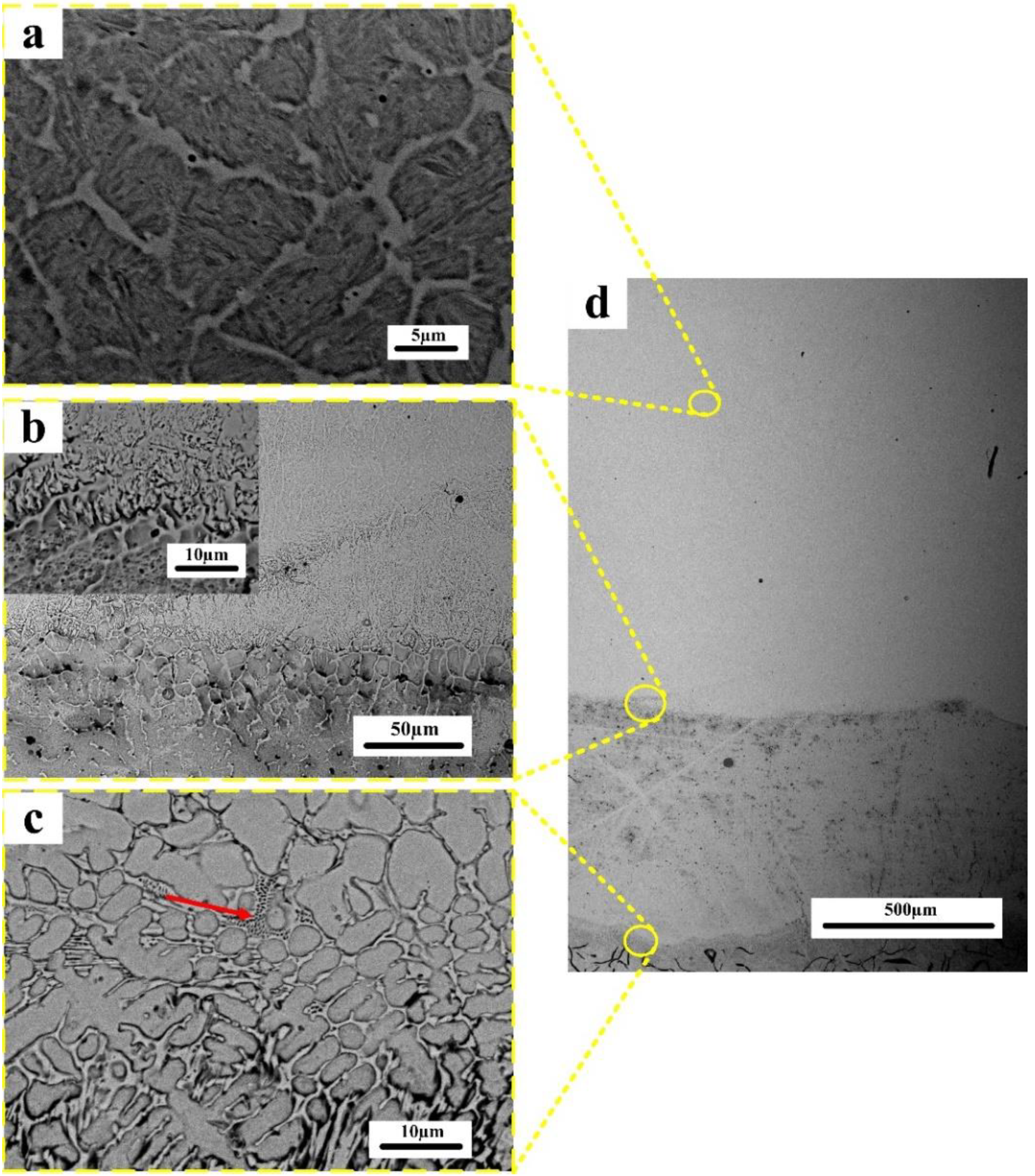
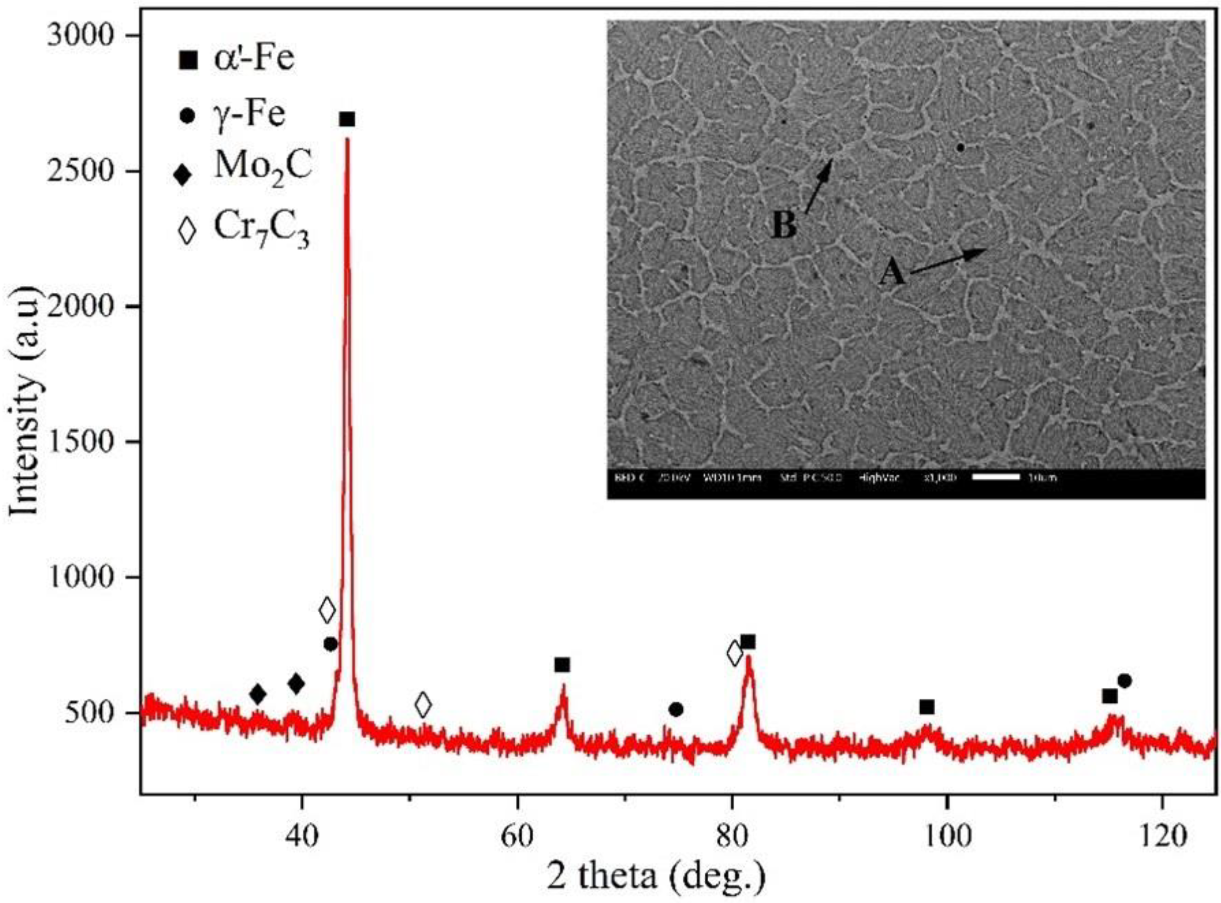
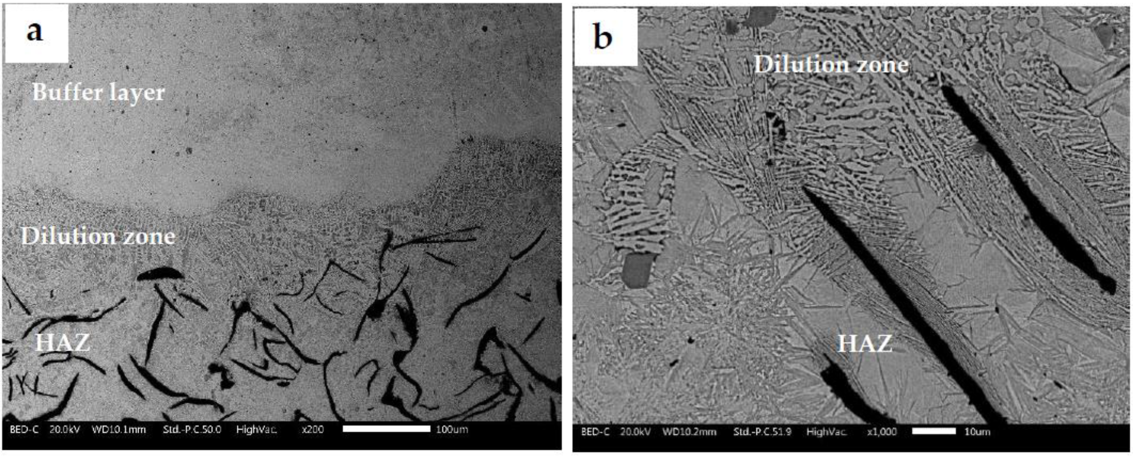
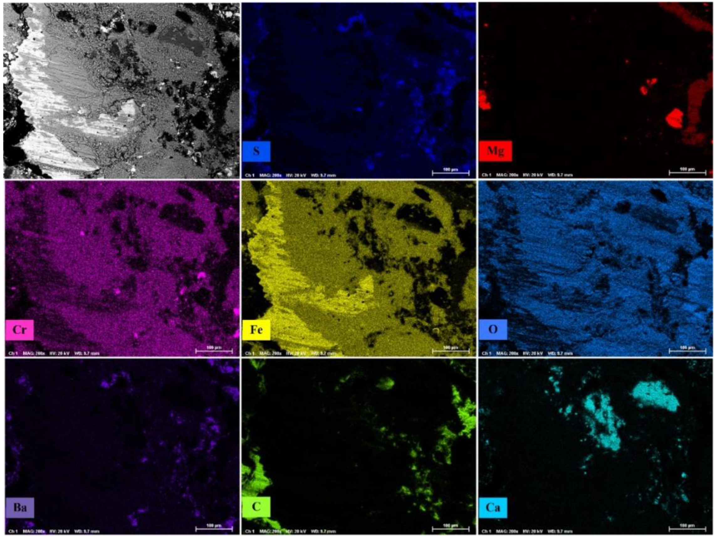
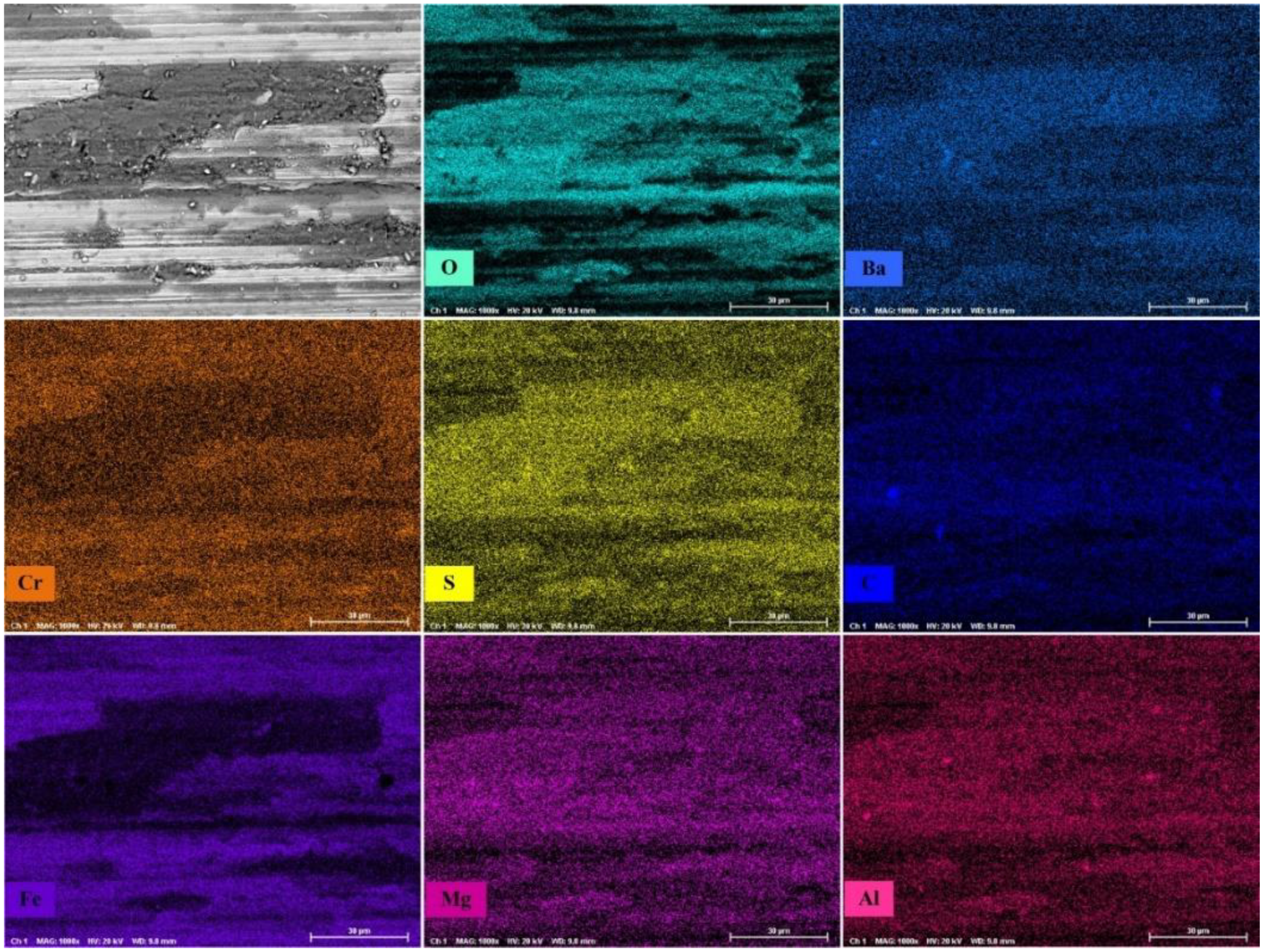
3.1. Microstructural Study

In Figure 2, the cross-sections of the coated disc without a buffer layer (Figure 2a) and with a buffer layer (Figure 2b) are compared. As can be seen in the high-magnification micrograph (Figure 2c), in the absence of the buffer layer, the coating is not well bonded to the GCI, and some cracks are visible at the interface. On the other hand, the deposition on the cast iron of the buffer layer, made of stainless steel, creates a defect-free, well-adherent coating (Figure 2d), on which the F55 steel, in turn, can be deposited without any crack formation. The coating’s thickness is 0.55 mm for the AISI 415 buffer layer and 3.55 mm for the F55 outer layer. The higher ductility of the stainless steel leads to an accommodation of the strains created by the thermal cycle associated with the laser deposition, thus reducing the risk of thermal cracks; moreover, its extremely low carbon content can solubilize an excess of carbon diffusing from the cast iron. As a further beneficial effect, this would limit the formation of carbides at the coating–substrate interface. Figure 3a–d show the complete cross-section of the disc coated with buffer and outer layers. Figure 3a shows the microstructure of the outer layer, Figure 3b shows the outer layer–buffer layer interface, Figure 3c shows the buffer layer–cast iron interface, and Figure 3d shows the complete section with the two interfaces—cast iron–buffer layer and buffer layer–outer layer. The microhardness profile measured along this cross-section is shown in Figure 4. The top coating (Figure 3a) features a two-phase microstructure: a needle-like structure (martensite) surrounded by a network of a second phase in a lighter color (carbides and retained austenite). XRD analysis collected on the top surface (Figure 5) indicated the presence of austenite and chromium and molybdenum carbides, together with the martensite structure, marked as α’ in the relevant XRD pattern (Figure 5). On the two points A and B of the SEM image included in Figure 5, EDXS analyses were carried out, confirming the higher amounts of Mo and Cr in the lighter phase network of point B (Table 3). The microhardness of this layer is around 700 HV0.3, as shown in Figure 4. According to literature data [25,26], the laser deposition of carbon steel leads to the formation of an interdendritic austenite + carbides phase, together with a martensitic matrix. In the buffer layer, the martensite has a much lower carbon content (0.03 vs. 0.35 wt%), resulting in a consistently lower microhardness (~300 HV0.3), as shown in Figure 4. This value of microhardness is consistent with literature data for AISI 415 stainless steel [26]. At the interface between F55 and the buffer layer (Figure 3b), larger dendritic grains are visible, resulting from the surface remelting produced by the deposition of the outer layer. Similarly, at the interface between the buffer layer and the GCI (Figure 3c), some carbides formed in the solidified interdendritic liquid, enriched in carbon, originating from the cast iron. A typical feature of ledeburite (eutectic austenite + cementite) is highlighted in Figure 3c. This carbide network forms upon cooling after the melting of a GCI surface layer, indicated as the dilution zone. The dilution (or remelting) zone is shown at higher magnification in Figure 6, which displays the interface between the disc and the buffer layer. The laser beam, in fact, creates a melt pool on the GCI surface, with the coating material fed into this and melted by the laser at the same time, resulting in the formation of the dilution zone. Despite the formation of carbides, the presence of a softer phase (low-carbon martensite) reduces the alloy’s brittleness, preventing the formation of cracks. On the other hand, when the dilution zone forms between F55 and GCI materials, the microstructure is too hard and brittle, resulting in the formation of the cracks highlighted in Figure 2c. Beneath the dilution zone, in the cast iron, the heating produced by the laser deposition process induces the formation of a heat-affected zone of ~500 μm thickness, characterized by the formation of martensite instead of pearlite and a consequently higher microhardness (600 HV0.3). The needle-like characteristic feature of martensite is visible in Figure 6b. Below the HAZ, the bulk GCI disc remains unaffected by the deposition process, and retains its pearlitic microstructure.

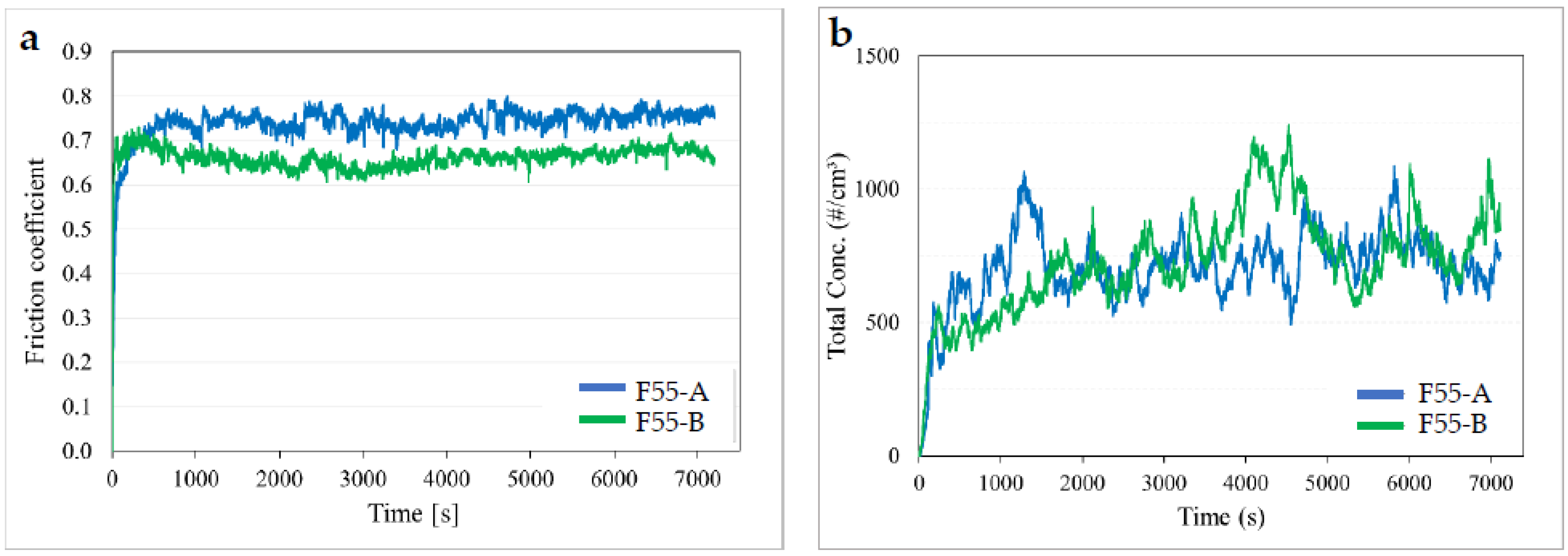
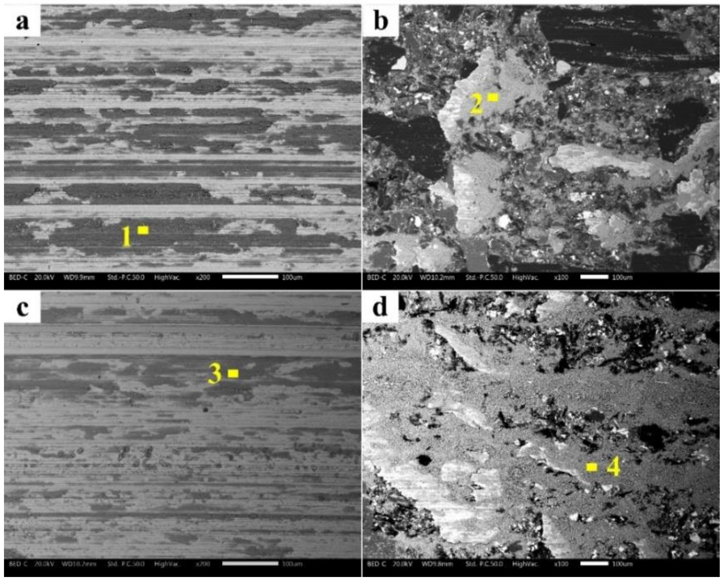
3.2. Pin-on-Disc Study

The more promising microstructure revealed by the F55 coating deposited on the AISI415 underlayer suggests carrying out PoD wear tests only on this coating system. Figure 7a shows the friction coefficient recorded during PoD tests of the two friction materials (A and B) sliding against the coated disc, with a short running-in period of ~2000 s before reaching a steady state. The average friction coefficients of F55-A and F55-B pairings in the steady state were 0.73 and 0.66, respectively. In Figure 7b, the total number of emissions regarding the tested sliding pairs indicates comparable total emissions for F55-A and F55-B.
Table 4 summarizes the results of the pin-on-disc tests. During the test, friction material “A” exhibited a larger friction coefficient than friction material “B”, yet the F55-A sliding pair had a higher wear resistance than the F55-B sliding pair. The F55-A sliding pair lost 58.0 mg and 84.8 mg of pin and disc weight, respectively. Conversely, the F55-B sliding pair lost 77.1 mg and 105.9 mg, respectively. The computed specific wear rate for comparing the coating effectiveness against used friction materials in the PoD test (last column of Table 4) showed that the Ka total of the F55-B pair was larger.
Figure 8 shows SEM micrographs of the worn-out pin and the counterpart disc surfaces after the PoD tests. The typical features of the friction layer can be seen in the planar view of the pin surfaces (Figure 8b,d), which consists of primary plateaus, mostly made up of metallic fibers (brighter phases), and secondary plateaus, made up of wear debris accumulated and compacted against primary plateaus (gray features against bright primary plateaus). The secondary plateaus on friction material “B”’s surface are more extended, but appear to be less compacted, as shown in Figure 8d. On the other hand, the secondary plateaus are less extended and more compacted on the pin surface of friction material “A” (Figure 8b). On the wear track of the counterpart discs, a material transfer is observed, which for friction material “A” (Figure 8a) is more widespread than for friction material “B”. In friction material “B”, the presence of barite contributes significantly to the establishment and extension of secondary plateaus [27]. This element can be found in the friction layer on the pin surface and the transferred layer on the disc, as illustrated by the EDXS results in Table 5. The X-ray element distribution maps of friction material “B” and the disc are shown in Figure 9 and Figure 10. The secondary plateaus right behind the primary plateaus are enriched with Fe, O, and Cr originating from both the pin and the coating composition. Some Ba is also detected, in line with the results of a previous study [27,28], and in agreement with the EDXS analysis of the highlighted area in Figure 8 (Table 5). The significant material transfer is responsible for the higher friction coefficients measured for these pairings compared to those observed in the case of the uncoated GCI disc, which were around 0.5 (Table 6) [27,28]. The material transfer is due to the high coating hardness, and results in an increase in the adhesive contribution of the friction coefficient and, in turn, higher emissions.
As shown by the SEM micrographs in Figure 8, the surface morphology of both the pin and disc obtained using friction materials A and B was not significantly different for the two tribological pairings. The set of X-ray maps in Figure 9, referring to the F55-B material pair, confirms that on the pin surface the friction layer is a result of the piling up and compaction of wear debris, to form secondary plateaus against iron fibers (primary plateaus).
As results from the compositional data in Table 5, for each tribopair, the similar composition of the friction layer on the pin and disc surface also indicates that a major contribution is made by the triboxidation of the coating material, although a contribution of abrasion is certainly present. The ploughing marks already visible in Figure 8a,c are also visible in Figure 10, in association with relevant X-ray elemental distribution maps. Abrasion marks that mostly form during the early bedding stage of the PoD tests are thereafter covered and, thus, protected, with patches of friction layer.

4. Discussion

As previously stated, the discs used for PoD tests were coated with an AISI 415 powder buffer layer, meant to improve GCI weldability. On the top of this buffer, two layers of F55 coating material were deposited to enhance the tribological performance of the cast-iron disc. Prior to PoD tests, the coated disc surfaces were mechanically polished to reduce the coating roughness to 0.25 μm [6]. As described in Section 3.1, the top layer was composed of martensite surrounded by an interdendritic network, featuring retained austenite and mixed carbides—mainly chromium- and molybdenum-based—as emerging from the XRD data (Figure 5). The formation of the interdendritic carbide was the result of microsegregation during solidification, which enriched the interdendritic areas of some elements, such as Cr and Mo. Similar results have been reported on a DED coating, with an H13 tool steel, similar in composition to F55, deposited onto a cast-iron substrate [29,30]. Carbon segregation from austenite to the interdendritic area occurs during the layer-by-layer DED process, with the subsequent formation of Cr and Mo carbides [30,31].
The indications emerging from the microstructural characterization confirm that the presence of the stainless steel underlayer prevents the formation of cracks in the F55 surface coating, which should guarantee adequate mechanical stability—a prerequisite for promising tribological behavior.
The hardness profile of the coating (Figure 4) shows that the contact surface with the friction materials has a hardness of around 700 HV0.3, which is significantly higher than that of the GCI substrate. To limit the contribution of abrasion—particularly during the early, bedding stages of the PoD tests—a preliminary mechanical polishing of the coating surface was conducted such that a surface roughness Ra of 0.25 μm was attained. Nevertheless, the high hardness of the coating asperities resulted in a significant material transfer from the pin to the disc, and a consequent increase in the adhesive contribution of both the friction coefficient and the wear, compared to those obtained in the case of uncoated cast iron.
The wear phenomena emerging from the analyses of the wear products of the PoD tests indicate a common behavior in the two tribological pairs: the F55 coating against friction materials “A” and “B”. From the evolution of the μ values (Figure 7a), it turns out that an initial bedding run-in stage was dominated by an abrasive mechanism possibly associated with the transfer of the carbides that, when extracted from the coating, become embedded into the pin surface. The progressive increase in the μ, due to the adhesion between the pin and the transferred friction material, was accompanied by a similar trend in the emission rate (Figure 7b). Both the μ and emission rate reached a steady state, which remained almost unaltered until the end of the test. Throughout the steady-state regime, triboxidation became the dominant wear mechanism, as indicated by the microstructural (Figure 8) and compositional data (Table 5 and Figure 9 and Figure 10) referring to the friction layer, which was found on both the pin and disc surfaces at the end of the tests.
The secondary plateaus were dynamically produced and disrupted by the friction-induced local shear stresses. The increased Fe oxide concentration in the secondary plateaus caused an increase in the contact adhesion forces [32], explaining the relatively high μ values. The continuous disruption of the secondary plateaus contributes to fine particle emission [33]. In comparison to friction material “A” (Table 2), the planar view of the friction material “B” pin (Figure 8d) shows relatively less compacted and extended secondary plateaus. This would be consistent with the higher wear and particulate matter emission rates recorded for this tribological pair (Table 4). Nevertheless, this emission difference is very limited and, in both cases, they are higher than those observed in case of GCI, which has a lower hardness and shows a dynamic material transfer from the disc to the pin. The lower μ of F55-B is compliant with the presence of barite—a filler material behaving to some extent as a solid lubricant [27], so as to partially balance the effects of abrasives such as aluminum oxides and magnesium oxides.

5. Conclusions

This investigation has demonstrated the following:
-
The successful deposition of a Ni- and Co-free steel-based coating onto a GCI substrate is feasible using DED technology, with the possibility of using this approach for restoring exhaust rotors of road vehicle brake discs;
-
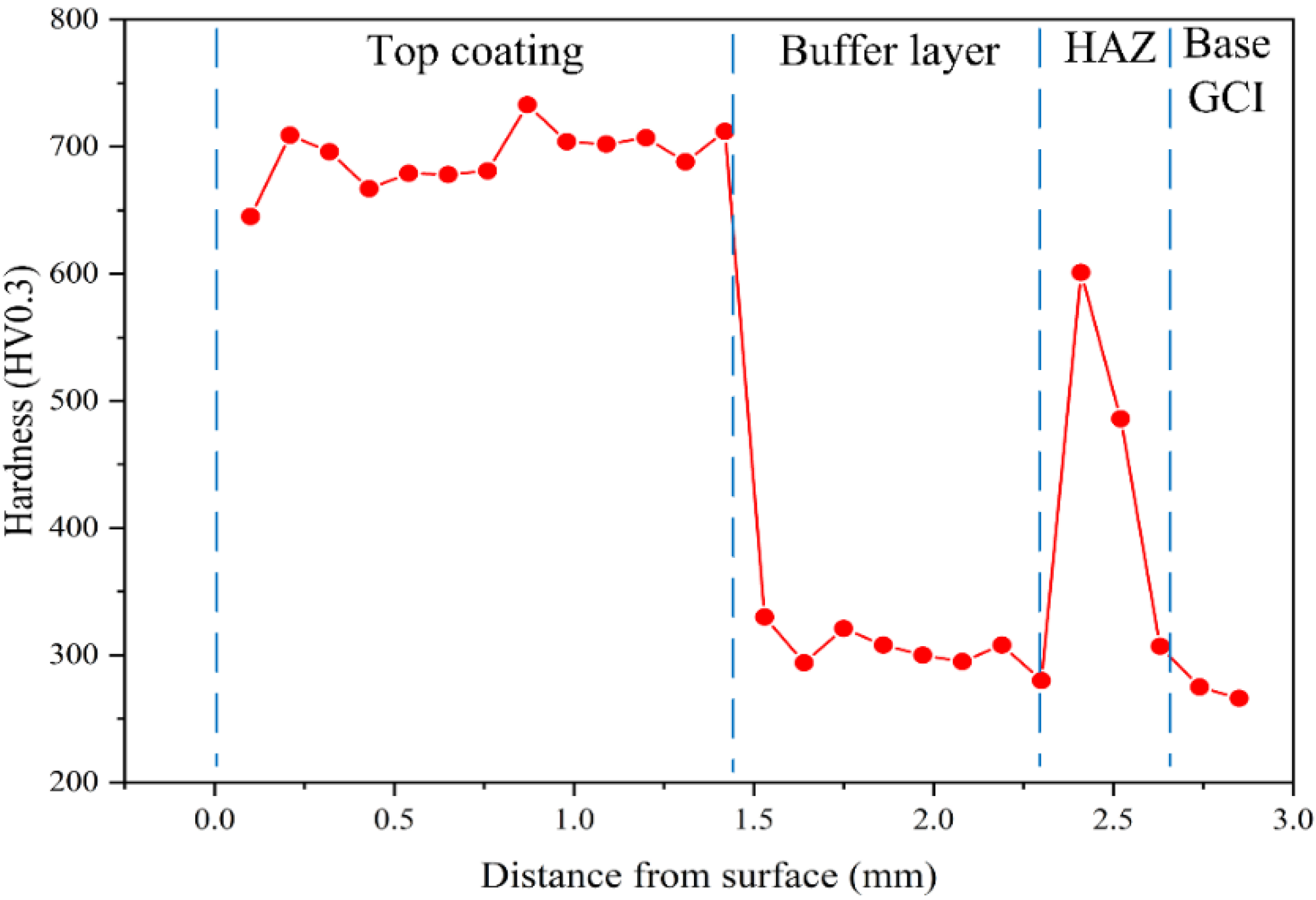
The stability of the surface coating is guaranteed by the pre-deposition of an AISI 415 stainless steel buffer layer, which accommodates the thermal stresses associated with this coating deposition process;
-
Considering the elevated hardness of the top layer, with respect to the typical hardness of friction materials for brake pads, a preliminary surface polishing is required before starting the tribological tests;
-
The early stages of the PoD tests are dominated by an abrasive wear mechanism, not mitigated by solid lubrication—as occurs with GCI discs—or the presence of graphite lamellas;
-
In the long run, relatively compacted and stable friction layers form at the interface between the mating surfaces, featuring relatively high m values.
On the basis of these results, it can be stated that the stainless steel buffer layer is necessary for the deposition of a well-adhered harder outer layer. The post-deposition surface finishing as well as the composition of the external layer should be optimized in order to achieve satisfactory tribological parameters—paramount to ensuring good braking performances and, at the same time, lower particulate matter emission.

Author Contributions

Conceptualization, H.R. and C.M.; methodology, H.R., C.M., G.S. and S.G.; formal analysis, H.R.; investigation, H.R., S.A. and M.P.; resources, S.A. and M.P.; writing—original draft preparation, H.R. and C.M.; writing—review and editing, C.M., S.A., M.P., S.G. and G.S.; supervision, G.S. and S.G. All authors have read and agreed to the published version of the manuscript.

Funding

This research was financed by Fondazione Caritro through the Foundation VRT (Fondazione per la Valorizzazione della Ricerca Trentina), grant “Impact Innovation 2021”, project name RiFreRiBE.

Institutional Review Board Statement

Not applicable.

Informed Consent Statement

Not applicable.

Data Availability Statement

The data presented in this study are available on request from the corresponding author.

Conflicts of Interest

The authors declare no conflict of interest.

References

  1. Aranke, O.; Algenaid, W.; Awe, S.; Joshi, S. Coatings for Automotive Gray Cast Iron Brake Discs: A Review. Coatings 2019, 9, 552. [Google Scholar] [CrossRef] [Green Version]
  2. Maluf, O.; Angeloni, M.; Tadeu, M.; Spinelli, M.D.; Wladimir, W.; Filho, B. Development of materials for automotive disc brakes. Pesqui. Technol. Minerva 2004, 2, 149–158. [Google Scholar]
  3. Olofsson, U.; Lyu, Y.; Åström, A.H.; Wahlström, J.; Dizdar, S.; Nogueira, A.P.G.; Gialanella, S. Laser Cladding Treatment for Refurbishing Disc Brake Rotors: Environmental and Tribological Analysis. Tribol. Lett. 2021, 69, 2–11. [Google Scholar] [CrossRef]
  4. Demir, A.; Samur, R.; Kiliçaslan, I. Investigation of the coatings applied onto brake discs on disc-brake pad pair. Metalurgija 2009, 48, 161–166. [Google Scholar]
  5. Federici, M.; Menapace, C.; Moscatelli, A.; Gialanella, S.; Straffelini, G. Pin-on-disc study of a friction material dry sliding against HVOF coated discs at room temperature and 300 °C. Tribol. Int. 2017, 115, 89–99. [Google Scholar] [CrossRef]
  6. Federici, M.; Menapace, C.; Moscatelli, A.; Gialanella, S.; Straffelini, G. Effect of roughness on the wear behavior of HVOF coatings dry sliding against a friction material. Wear 2016, 368–369, 326–334. [Google Scholar] [CrossRef]
  7. Federici, M.; Menapace, C.; Mancini, A.; Straffelini, G.; Gialanella, S. Pin-on-disc study of dry sliding behavior of Co-free HVOF-coated disc tested against different friction materials. Friction 2021, 9, 1242–1258. [Google Scholar] [CrossRef]
  8. Li, Y.; Dong, S.; Yan, S.; He, P.; Xu, B. Phase evolution of ductile iron during laser cladding processing. Surf. Coat. Technol. 2018, 339, 37–47. [Google Scholar] [CrossRef]
  9. Nurminen, J.; Näkki, J.; Vuoristo, P. Laser cladding on cast iron substrates. In ICALEO 2005—Congress Proceedings, Proceedings of the 24th International Congress on Applications of Lasers and Electro-Optics, Miami, FL, USA, 31 October–3 November 2005; Laser Institute of America: Orlando, FL, USA, 2005; pp. 655–659. [Google Scholar] [CrossRef]
  10. Thompson, S.M.; Bian, L.; Shamsaei, N.; Yadollahi, A. An overview of Direct Laser Deposition for additive manufacturing; Part I: Transport phenomena, modeling and diagnostics. Addit. Manuf. 2015, 8, 36–62. [Google Scholar] [CrossRef]
  11. Shim, D.S.; Baek, G.Y.; Lee, S.B.; Yu, J.H.; Choi, Y.S.; Park, S.H. Influence of heat treatment on wear behavior and impact toughness of AISI M4 coated by laser melting deposition. Surf. Coat. Technol. 2017, 328, 219–230. [Google Scholar] [CrossRef]
  12. Rai, A.K.; Srinivasulu, B.; Paul, C.P.; Singh, R.; Rai, S.K.; Mishra, G.K.; Bontha, S.; Bindra, K.S. Development of thick SiC coating on thin wall tube of zircaloy-4 using laser based directed energy deposition technique. Surf. Coat. Technol. 2020, 398, 126088. [Google Scholar] [CrossRef]
  13. Kim, T.H.; Baek, G.Y.; Jeon, J.B.; Lee, K.Y.; Shim, D.s.; Lee, W. Effect of laser rescanning on microstructure and mechanical properties of direct energy deposited AISI 316L stainless steel. Surf. Coat. Technol. 2021, 405, 126540. [Google Scholar] [CrossRef]
  14. Lyu, Y.; Leonardi, M.; Mancini, A.; Wahlström, J.; Olofsson, U. Tribology and Airborne Particle Emission of Laser-Cladded Fe-Based Coatings versus Non-Asbestos Organic and Low-Metallic Brake Materials. Metals 2021, 11, 1703. [Google Scholar] [CrossRef]
  15. Van Acker, K.; Vanhoyweghen, D.; Persoons, R.; Vangrunderbeek, J. Influence of tungsten carbide particle size and distribution on the wear resistance of laser clad WC/Ni coatings. Wear 2005, 258, 194–202. [Google Scholar] [CrossRef]
  16. Dizdar, S.; Lyu, Y.; Lampa, C.; Olofsson, U. Grey Cast iron brake discs laser cladded with nickel-tungsten carbide-Friction, wear and airborne wear particle emission. Atmosphere 2020, 11, 621. [Google Scholar] [CrossRef]
  17. Fernández, E.; Cadenas, M.; González, R.; Navas, C.; Fernández, R.; de Damborenea, J. Wear behaviour of laser clad NiCrBSi coating. Wear 2005, 259, 870–875. [Google Scholar] [CrossRef] [Green Version]
  18. Menapace, C.; Mancini, A.; Federici, M.; Straffelini, G.; Gialanella, S. Characterization of airborne wear debris produced by brake pads pressed against HVOF-coated discs. Friction 2020, 8, 421–432. [Google Scholar] [CrossRef] [Green Version]
  19. Leyssens, L.; Vinck, B.; van der Straeten, C.; Wuyts, F.; Maes, L. Cobalt toxicity in humans—A review of the potential sources and systemic health effects. Toxicology 2017, 387, 43–56. [Google Scholar] [CrossRef]
  20. Denkhaus, E.; Salnikow, K. Nickel Essentiality, Toxicity, and Carcinogenicity. 2002. Available online: www.elsevier.com/locate/critrevonc (accessed on 16 December 2021).
  21. Bastian, S.; Busch, W.; Kühnel, D.; Springer, A.; Meißner, T.; Holke, R.; Scholz, S.; Iwe, M.; Pompe, W.; Gelinsky, M.; et al. Toxicity of tungsten carbide and cobalt-doped tungsten carbide nanoparticles in mammalian cells in vitro. Environ. Health Perspect. 2009, 117, 530–535. [Google Scholar] [CrossRef] [Green Version]
  22. Lee, S.; Kim, J.; Shim, D.S.; Park, S.H.; Choi, Y.S. Micro-Cracking in Medium-Carbon Steel Layers Additively Deposited on Gray Cast Iron Using Directed Energy Deposition. Met. Mater. Int. 2020, 26, 708–718. [Google Scholar] [CrossRef]
  23. Zhang, D.; Li, Z.; Fan, H.; Rui, H.; Gao, F. Microstructure and tribological properties of Fe-based laser cladding layer on nodular cast iron for surface remanufacturing. Coatings 2021, 11, 974. [Google Scholar] [CrossRef]
  24. Yu, J.; Liu, Y.; Song, B.; Wang, J. Microstructure and properties of Fe-based alloy coating on gray cast iron fabricated using induction cladding. Coatings 2020, 10, 801. [Google Scholar] [CrossRef]
  25. Chen, Z.K.; Zhou, T.; Zhao, R.Y.; Zhang, H.F.; Lu, S.C.; Yang, W.S.; Zhou, H. Improved fatigue wear resistance of gray cast iron by localized laser carburizing. Mater. Sci. Eng. A 2015, 644, 1–9. [Google Scholar] [CrossRef]
  26. Leymonie, C. Structural Transformation and Mechanical Properties of 13% Cr-4% Ni Steels. Power Ind. Res. 1982, 2, 17–33. Available online: http://ci.nii.ac.jp/naid/80001250991/en/ (accessed on 13 January 2022).
  27. Menapace, C.; Leonardi, M.; Matějka, V.; Gialanella, S.; Straffelini, G. Dry sliding behavior and friction layer formation in copper-free barite containing friction materials. Wear 2018, 398–399, 191–200. [Google Scholar] [CrossRef]
  28. Lyu, Y.; Leonardi, M.; Wahlström, J.; Gialanella, S.; Olofsson, U. Friction, wear and airborne particle emission from Cu-free brake materials. Tribol. Int. 2020, 141, 105959. [Google Scholar] [CrossRef]
  29. Fan, L.; Dong, Y.; Chen, H.; Dong, L.; Yin, Y. Wear Properties of Plasma Transferred Arc Fe-based Coatings Reinforced by Spherical WC Particles. J. Wuhan Univ. Technol.-Mater. Sci. Ed. 2019, 34, 433–439. [Google Scholar] [CrossRef]
  30. Zhou, S.; Zeng, X. Growth characteristics and mechanism of carbides precipitated in WC-Fe composite coatings by laser induction hybrid rapid cladding. J. Alloys Compd. 2010, 505, 685–691. [Google Scholar] [CrossRef]
  31. Lee, S.; Yu, J.H.; Park, S.H.; Shim, D.S.; Choi, Y.S. Effect of carbon content in steel powder feedstock on impact toughness and microstructure of additively manufactured cast iron by directed energy deposition. J. Mater. Res. Technol. 2021, 15, 189–198. [Google Scholar] [CrossRef]
  32. Straffelini, G.; Gialanella, S. Airborne particulate matter from brake systems: An assessment of the relevant tribological formation mechanisms. Wear 2021, 478–479, 203883. [Google Scholar] [CrossRef]
  33. Straffelini, G. Springer Tracts in Mechanical Engineering Friction and Wear Methodologies for Design and Control; Springer: Berlin/Heidelberg, Germany, 2015; Available online: http://www.springer.com/series/11693 (accessed on 16 December 2021).
Figure 1. (a) Microstructure of the pearlitic cast-iron disc; (b) microstructure of the F55 granular powder.
Metals 12 00465 g001
Figure 2. Cross-section view of the coated disc: (a) without buffer layer, and (b) with buffer layer; (c) higher magnification of the interface without a buffer layer; (d) higher magnification of the interface with a buffer layer.
Metals 12 00465 g002
Figure 3. Cross-section of the F55 + AISI415 coating on GCI: (a) outer layer; (b) outer layer–buffer layer interface; (c) buffer layer–GCI interface (melted zone), arrow indicates a typical ledeburitic microstructure; (d) complete cross-section of the coated GCI, with buffer layer and disc.
Metals 12 00465 g003
Figure 4. Hardness profile of the F55 + AISI415 coating, from the top surface down to the substrate.
Metals 12 00465 g004
Figure 5. XRD pattern of the disc’s top layer surface. Inset: SEM image of the top layer, showing the microstructure of the analyzed surface, with the indication of the points “A” and “B”, where EDXS analyses were carried out to evaluate the local composition (see Table 3).
Metals 12 00465 g005
Figure 6. (a) GCI–buffer layer interface and (b) melted zone and heat-affected zone at higher magnification.
Metals 12 00465 g006
Figure 7. (a) Friction coefficient and (b) emissions related to friction materials A and B sliding against the coated GCI disc.
Metals 12 00465 g007
Figure 8. SEM of the pin and counterpart F55 + AISI415-coated disc: (a) coating surface and (b) pin A; (c) coating surface and (d) pin B. Numbers 1, 2, 3, 4 placed on secondary plateaus where EDXS analyses were carried out (results in Table 5).
Metals 12 00465 g008
Figure 9. Element distribution X-ray maps on the worn-out surface of friction material B tested against the F55-coated disc.
Metals 12 00465 g009
Figure 10. Element distribution X-ray map of the F55 + AISI415-coated disc surface after PoD testing against friction material B.
Metals 12 00465 g010
Table 1. Chemical composition of the coating materials and substrate (wt%).
MaterialFeCCrNiMoMnSiS
AISI415Bal.<0.0512–143.5–4.50.3–0.7<1.5<0.7<0.015
F55Bal.0.357-2.21.10.3-
GCIBal.3.8---0.651.90.06
Table 2. EDXS analysis of the friction materials used for PoD tests. Note: carbon concentration was not evaluated.
Elements (wt%)AB
O26.7 ± 1.430.7 ± 0.8
Mg6.3 ± 0.98.4 ± 0.4
Al5.1 ± 0.27.1 ± 0.1
S3.6 ± 1.26.5 ± 0.2
Si2.9 ± 0.65.3 ± 0.7
Ca6 ± 0.84.6 ± 0.1
Zn12.4 ± 1.57.8 ± 0.6
Cr3.1 ± 0.21.7 ± 0.2
Fe24.8 ± 2.313.1 ± 0.8
Sn9.1 ± 0.53.5 ± 0.2
Ba-11.3 ± 0.4
Table 3. EDXS analysis of the indicated areas in Figure 5.
ElementA
Mass Norm. (%)
B
Mass Norm. (%)
Fe85.7880.62
Cr6.198.45
Mo1.83.38
Mn0.801.05
Si0.280.29
C5.156.21
Table 4. Summary of the PoD tests’ results.
SampleΔM Disc (mg)Δm pin (mg)Emissions #/cm3µ Ave.Kpin × 10−14 (Nm−2)KDisc × 10−14 (Nm−2)Ktotal × 10−14 (Nm−2)
F55-A84.8 ± 8.458 ± 4.8731 ± 810.73 ± 0.074.60 ± 0.31.93 ± 0.136.53
F55-B105.9 ± 477.1 ± 8807 ± 550.66 ± 0.046.12 ± 0.92.84 ± 0.288.96
Table 5. EDXS analysis of the highlighted area in Figure 8 (points 1, 2, 3, 4).
PointFeOCrBaZnSSnMoOther
159.0623.775.03-4.421.601.600.46Bal.
2 58.3726.844.79-3.251.131.670.45Bal.
358.4724.624.133.522.403.021.951.1Bal.
458.1627.053.951.811.611.110.951.2Bal.
Table 6. Wear test results of friction materials A and B against uncoated GCI.
Brake CoupleCOFKa pin × 1014
(Nm−2)
Ka disc × 1014
(Nm−2)
Emissions
#/cm3
GCI/A0.54.961.13446
GCI/B 0.484.731.41679
Publisher’s Note: MDPI stays neutral with regard to jurisdictional claims in published maps and institutional affiliations.

