Article

Influences of Post-Heat Treatment on the Microstructure Evolution and Creep Properties of Ni-Based Superalloy IN718 Fabricated by Electron Beam Melting

1
Department of Mechanical Systems Engineering, Tokyo Metropolitan University, 1-1, Minami-Osawa, Hachioji-City, Tokyo 192-0397, Japan
2
Department of Mechanical Engineering, Nagaoka University of Technology, 1603, Kamitomioka, Niigata 940-2188, Japan
*
Authors to whom correspondence should be addressed.
Metals 2022, 12(3), 446; https://doi.org/10.3390/met12030446
Submission received: 24 January 2022 / Revised: 25 February 2022 / Accepted: 1 March 2022 / Published: 4 March 2022
(This article belongs to the Special Issue Advances in Additive Manufacturing of Metals)

Abstract

:
In this study, the Ni-based superalloy IN718, fabricated using an electron beam melting process, was investigated in as-built and various heat-treated conditions. The relationships between the microstructure characteristics and creep properties were elucidated. Under testing conditions of 650 °C and 650 MPa, the direct-aged specimen exhibited the lowest steady-state creep rate, at 0.15 × 10⁻⁸ s−1. The superior creep resistance can be attributed to the higher volume fraction of γ’/γ”-strengthening precipitates within the grain and fine δ precipitates along the grain boundaries. Being coherent to the γ matrix, the nano-sized γ’/γ” precipitates effectively hindered the dislocation motion in the grain interior. In addition, controlled grain boundary δ precipitates inhibited grain boundary sliding and decelerated the steady-state creep strain rate during creep deformation.

1. Introduction

Developed in the early 1960s, the nickel-iron based IN718 alloy features high-temperature strength and outstanding corrosion resistance up to 700 °C. IN718 derives its high-temperature strength from the ordered body-centered tetragonal γ” phase (Ni3Nb, D022, ordered BCT) and face-centered cubic γ’ phase (Ni3 (Al, Ti), L12, ordered FCC), which are both coherent to the matrix. For the peak-aged IN718 alloy, the fraction of γ” reaches 15 vol.% and thus contributes to the major hardening effect compared to the 4 vol.% γ’ phase [1]; however, when exposed to a temperature higher than 700 °C, the meta-stable γ” precipitates tend to transform rapidly into the thermodynamically stable δ phase (Ni3Nb, orthorhombic). The formation of the δ phase, which is incoherent to the matrix, lowers the strength of IN718 by depleting the major strengthened γ” phase, thereby limiting the operating temperature range of IN718 [2]. Nevertheless, the controlled grain boundary δ phase offers some advantages, such as improved grain stability and resistance to creep deformation [3].
As an age-hardenable alloy, IN718 possesses excellent weldability due to its retarded γ” precipitation-hardening rate and low cracking susceptibility, thus making IN718 suitable for various additive manufacturing (AM) processes [4,5]. AM is a new advanced manufacturing process that enables the fabrication of components with complex designs, which are problematic in manufacturing using traditional methods. Electron beam melting (EBM) is one of the most popular and widely used metal additive manufacturing techniques for producing high-density metallic parts by melting metal powders in a layer-by-layer manner using a high-power electron beam [6]. Powder preheating in the EBM process relieves the residual stress in the final built parts by lowering the thermal gradient between the layers [7]. The vacuum environment in the built chamber prevents oxidation during the EBM process and makes it highly suitable for processing reactive materials such as TiAl-based alloys [8,9]. Considering its benefits, EBM was applied to manufacture high-performance IN718 with complex components for various applications, especially aerospace applications.
In recent years, researchers have tried to optimize the microstructure and the precipitates for EBM-built IN718 by tailoring the post-heat-treatment to meet requirements for various mechanical properties. Strondl et al. reported the tensile properties of an EBM-built IN718 that were comparable to those of the conventionally wrought IN718 alloy [10]. Goel et al. successfully reduced the defects within EBM-built IN718 using a hot isostatic pressing (HIP) process [11]. Nandwana et al. showed the possibility of grain-size control without the help of a phase during the HIP process by closely controlling the building temperature [12]. Deng et al. proposed the direct-aging process, which effectively avoided the formation of the δ phase, as the optimal heat treatment for EBM-built IN718 and its room-temperature tensile properties [13]. Kirka et al. identified a three-layer structure along the building direction of EBM-built IN718 bulk and declared that the network of needle-like δ phase formed at the lower level of the bulk weakened the tensile properties [14].
According to the abovementioned literature, the δ phase plays a dominant role in the tensile properties of EBM-built IN718; however, little emphasis has been placed on elucidating the influence of the δ phase on the creep properties. In this research, we focus on the creep properties of EBM-fabricated IN718 heat-treated at various conditions. The evolution of the microstructure and its relationship to the creep properties have been elucidated. As the post-heat-treatment that optimizes creep properties has not been published yet, this study aims to provide guidelines for optimizing heat treatment for the EBM-built IN718 alloy.

2. Materials and Methods

In this study, we used Arcam Inco718 powders (Arcam AB, Mölndal, Sweden) with the nominal composition given in Table 1. Mostly, these powders are spherical or irregular in shape, with few satellite particles on the surface. A cubic block with dimensions of 45 × 45 × 45 mm3 was fabricated using Arcam A2X EBM machine (Arcam AB, Mölndal, Sweden) and sliced into several 3 mm-thick plates using a spark cutter. The sliced plates were heat-treated, following the conditions listed in Table 2 for the creep test and microstructure observation. All the heat treatments were performed in a box furnace (FT-105FM, FULL-TECH, Osaka, Japan). To prevent oxidation, the specimens were sealed in quartz capsules under a vacuum. The dog-bone-shaped specimens for creep tests with a gauge length of 19.6 mm and a 2.5 × 3.0 mm2 cross section were cut using a wire electro-discharge machine (WEDM, HS-300, Brother Industries Ltd., Nagoya, Japan) parallel to the building direction (BD). The tensile creep tests were carried out at 650 °C, using an RT-20 constant-load creep testing machine with an attached Bethel-4A automatic temperature control unit (Toshin Kogyo Co., Ltd., Tokyo, Japan) under a stress level of 650 MPa. The creep specimens were heated from room temperature to a selected test temperature at a heating rate of 10 °C/min. After 30 min of soaking time to obtain a uniform and stable temperature, the tests were performed until fracture, followed by furnace cooling. The temperature fluctuation during the creep test was controlled within ±2 °C using k-type thermocouples that were in contact with the specimen. The creep strain was measured during tests using a linear variable differential transducer (LVDT) (PEACOCK, Model D-10S, OZAKI MFG. Co. Ltd., Tokyo, Japan) extensometer mounted on the specimen. To characterize the microstructure, the specimens were sequentially ground with SiC emery papers from 240 to 2000 grit and then underwent metallographic polishing with 9 and 3 µm diamond suspensions, and finally were polished with colloidal silica suspension. The electrochemical etching was performed using an electrolytic solution of phosphorus acid and water (1:4, by volume) at 25 °C/2.5 V for 3–5 s. The microstructures were analyzed using a scanning electron microscope (SEM, S-3700N, Hitachi Ltd., Tokyo, Japan) with an attached electron backscattered electron (EBSD) detector (HKL Nordlys, Oxford Instrument, Abingdon, UK). The EBSD data were further analyzed using HKL–channel 5 software. A field-emission scanning electron microscope (FE-SEM, JSM-7800F Prime, JEOL Ltd., Tokyo, Japan) was used to obtain a high resolution. The nano-sized precipitates and the dislocations were observed using a transmission electron microscope (TEM; JEM-2010HC, JEOL, Tokyo, Japan) operating at an accelerating voltage of 200 kV. TEM samples were prepared by grinding to 60–100 µm thick through mechanical polishing, and 3 mm discs were punched out. The discs were then electro-polished using a twin-jet electro-polisher (Model 110, E.A. Fischione Instruments, Inc., Export, PA, USA) with an electrolytic solution consisting of 10% perchloric acid and 90% ethanol at −30 °C/30 V for 5–7 min.

3. Results

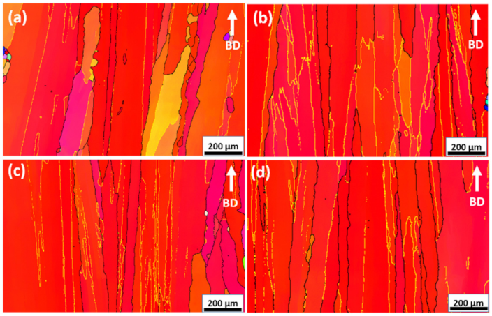
3.1. Microstructural Features

The EBSD inverse pole figure (IPF) map of the as-built specimen along the building direction given in Figure 1 revealed high-aspect-ratio columnar grains with strong <100> crystallographic orientation along the building direction of the EBM process. However, occasionally a few fine equiaxed grains of random crystallographic orientation were also observed. The equiaxed grains formed due to solidification conditions such as the thermal gradient and growth rate, both of which favor the formation of new fine grains [15]. Another possible reason could be the presence of nano-sized Al-rich oxide particles or the dendritic fragments caused by the highly focused beam, which introduces new equiaxed grains of random crystallographic orientations [16].
The EPMA elemental maps for the as-built specimen are shown in Figure 2, revealing the presence of spherical black Al-rich oxides (Al2O3) and TiN. The impurity contamination very likely came from the powder feedstock, which is more vulnerable to contamination. The Al2O3 particles were found to be typically less than 1 µm. The STEM-EDS analysis in Figure 3 shows the “core-shell” structure of aluminum oxide (Al2O3) at the center and surrounded by carbo-nitrides. This core-shell structure formation suggests that carbo-nitrides typically nucleate and grow at the Al2O3 interface during solidification.
As shown in Figure 4a, the SEM micrographs of the AB specimen reveal an array of MC carbides (M = Nb, Ti), precipitated both on the grain boundaries and in the grain interior. These carbides were mostly aligned parallel to the building direction. The magnified view in Figure 4b shows very fine precipitates throughout the matrix, as well as fine-sized δ precipitates formed along the grain boundary with the precipitation-free zone (PFZ). These fine precipitates can be identified as γ’/γ” phases using TEM bright-field (BF) and dark-field (DF) images coupled with their corresponding selected-area diffractions (SAD), as shown in the insert of Figure 5.
Figure 6 shows the EBSD inverse pole figure (IPF) map of the post-heat-treated specimens. After the post-heat treatments, the microstructure appeared to be unaffected in terms of grain morphology, as it still maintained a columnar-grained structure with a preferential <100> crystallographic orientation. In general, columnar grains are considered to be beneficial for enhancing the creep properties of Ni-based superalloys, especially with <100> or <111> orientations [18,19,20,21,22]. Because of the high thermal stability of Al2O3 and TiN and the high dissolution temperature of MC carbide (approximately 1250 °C [23]), these phases remained intact after the heat treatments. The microstructure of the DA specimen is shown in Figure 7a,b. The grain boundary δ precipitates became slightly longer than their counterparts in the AB specimen. Assisted by the two-step aging post-treatment, the size of the strengthening γ’/γ” phases also increased, as shown in Figure 7b. For the SA specimen, both the γ” and γ’ phases within the matrix were expected to dissolve at the 980 °C/1 h stage, whereas a high fraction of δ phase forms along the grain boundaries. However, in the case of the HSA specimen, not only were the γ’/γ” phases dissolved, but the δ phase was also dissolved at 1095 °C/1 h, and the grain boundary was kept clean up to the stage of 955 °C/6 h, during which the δ phase formed rapidly. According to previous research, the maximum intergranular δ phase precipitation is found in the 900 °C–980 °C temperature range due to higher diffusional rates and accelerated nucleation at grain boundaries [23,24]. Therefore, the grain boundary δ precipitates grew larger and their shape changed from a fine disc to a thick needle shape in both the SA and HSA specimens shown in Figure 7c,e, respectively. These specimens underwent strengthening through the following two-step aging heat treatment. However, strengthening γ’/γ” phases in SA and HSA specimens, as presented in Figure 7d,f, became fine in size compared to the DA specimen. The only difference between HSA and HA is the 955 °C/6 h secondary solution treatment step, which is performed to achieve a higher volume fraction of acicular δ precipitates along the grain boundary. Thus, the SEM micrographs of the HA specimen in Figure 7g show the grain boundaries that are free of δ precipitates and fine γ’/γ” phases in the grain interior, as shown in Figure 7h.

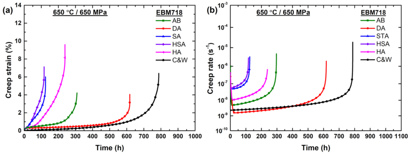
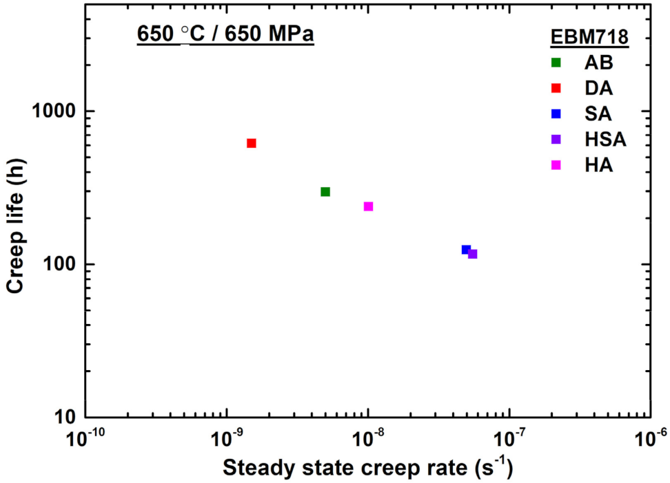
3.2. Creep Properties

Figure 8 presents the creep curves of various heat treatment specimens along the building directions, tested at 650 °C/650 MPa. For comparison, the C&W IN718 creep curve is also included. The corresponding creep properties, such as creep life, elongation, and creep strain rates, are summarized in Table 3. The creep rupture life of the AB specimen was approximately 296 h. The DA specimen showed a rupture life of 617 h, which is twice that of the AB specimen. Both AB and DA specimens displayed conventional creep curves with a short primary creep regime and a longer steady-state regime, followed by an accelerated tertiary regime. In contrast, both the SA and HSA specimens showed early tertiary regimes with shorter creep rupture lives of 124 h and 116 h, respectively. The HA specimen exhibited a creep life of 239 h with an elongation of 9.66%. By comparison, the creep life of HA was shorter than those of the AB and DA specimens, which had fine δ precipitates along their grain boundaries. However, the elongation of the HA specimen was roughly 2.5 times higher than those of AB and DA. The DA specimen had the lowest steady-state creep rate, as low as 0.15 × 10⁻⁸ s−1. The creep rates of the AB and SA specimens were 0.50 × 10⁻⁸ s−1 and 5.0 × 10⁻⁸ s−1, respectively. The creep rate of the HT specimen reached 5.5 × 10⁻⁸ s−1. The HA specimen showed a creep rate of 1.0 × 10⁻⁸ s−1.

4. Discussion

4.1. Effect of the Post-Heat Treatments on Microstructure Evolution

Microstructural aspects, such as the chemical composition, chemical distribution, morphology, precipitate size, and volume fraction of precipitates, are predominantly controlled via the processing conditions and subsequent post-heat treatments. In our current work, the powder bed was preheated to 800 °C and was maintained at that temperature throughout the EBM process. After the completion of the build, the block was allowed to cool. For the IN718 alloy, the precipitation of γ’/γ”-strengthening phases occurs in the temperature range of 650 °C–900 °C, and the formation of the thermodynamically stable δ phase takes place in the temperature range of 750 °C–1020 °C. As a result, the preheating and cooling processes act together as an in situ heat treatment, promoting the precipitation of γ’/γ”-strengthening phases and fine δ precipitates along the grain boundary, with a clear γ”-depleted region in the AB specimen. However, the EBM processing conditions are sufficient to precipitate a relatively high amount of γ’/γ” but not enough to obtain peak-aging. During two-step direct aging, the size and volume fraction of γ’/γ” precipitates in the AB specimen increased, as the temperature conditions favored the peak aging of these precipitates. In addition, the grain boundary δ phase also tends to grow larger as it accelerates the transformation of the γ” phase into the δ phase. For SA and HSA specimens, the dissolution of γ’/γ” and δ precipitates (the solvus temperatures of γ’/γ” and δ are around 900 °C and 1020 °C, respectively [23]) into the γ matrix results in homogenization of the chemical composition. Additionally, the grain boundaries serve as preferred nucleation sites for the needle-like δ precipitation [24]. As a result, the homogenized composition and preferential nucleation lead to thicker δ precipitates at the grain boundary. Since both δ and γ” phases have the same chemical composition (Ni3Nb), the precipitation of the coarser δ phase along the grain boundary consumes the available Nb content along the vicinity of the grain boundary and reduces the volume fraction of the major strengthening γ” phase precipitation within the grain during the subsequent two-step aging process. Owing to both the homogenized chemical composition and the modified heat treatment that prevents δ precipitate formation, the HA specimen obtains a higher volume fraction of γ’/γ” precipitates than SA and HSA specimens.

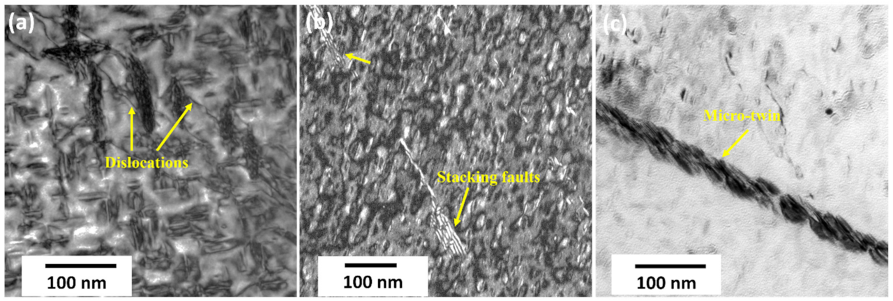
4.2. Effect of Precipitates on Creep Properties

Based on the results of a study by Han and Chaturvedi, for alloy IN718 tested at 650 °C/650 MPa, the predominant creep mechanism should be the dislocation power-law creep mechanism [25]. The steady-state creep rate equation can be written as
ε s s ° = A σ a σ 0 G n e G b k T   e x p Q e R T
where ε s s ° is the steady-state creep rate, A is a constant,   σ a is the applied stress,   σ 0 is the threshold stress opposing the dislocation motion, ne is the effective stress exponent, b is the Burgers vector, Qe is the effective activation energy, T is the creep temperature, and R is the gas constant. Moreover, the steady-state creep rate can also be expressed as
ε s s ° = ε g ° + ε g d s ° + ε d i °
where ε g ° and ε g d s ° represent the contribution of the dislocation process occurring within the grains and the contribution of the grain boundary sliding, respectively. ε d i ° represents the stress-directed vacancy diffusion through the lattice and the grain boundary [26]. In this study, the steady-state strain rate ( ε s s ° ) is primarily controlled by the dislocation motion within the grains, as well as by the grain boundary sliding. In other words, the ε s s °   depends mainly on the volume fraction and the size of the primary strengthening γ’/γ” and δ phases obtained during various heat treatment conditions.
In IN718, the growth rate of γ’/γ” precipitates follows the Lifshitz–Slyozov–Wagner (LSW) theory of diffusion-controlled growth [27,28]. According to LSW theory, the average particle size (d) is proportional to the cube root of aging time (t), i.e., d     t 1 / 3 . During the EBM process, the in situ heat treatment forms a relatively coarse γ’/γ” precipitation in the AB specimen. In subsequent direct-aging heat treatment, these pre-existing γ’/γ” precipitates coarsen further, owing to the longer aging time. On the other hand, following solutionization/homogenization heat treatment, the relatively coarse pre-existing γ’/γ” precipitates dissolve and re-precipitate into a fine size during the aging heat treatment for the STA, HSA, and HA specimens. The post-deformed TEM micrographs are shown in Figure 9, demonstrating the formation of stacking faults and micro-twins, which are characteristic features of the dislocation shear mode of deformation. In shearing deformation, the dependence of the steady-state creep rate ( ε s s ° ) on the average particle size (d) of γ” precipitates can be expressed as ε s s °     d 2 [29]. Thus, it is considered that the resistance to creep deformation is higher in the DA specimen with a larger particle size (40 nm) of γ’/γ” precipitates, resulting in the lowest creep rate and longest creep life, as shown in Figure 10.
According to previous studies, it is clear that the grain boundary microstructure strongly influences the creep behavior of IN718 [30,31]. It has been reported that the existence of δ precipitates at the grain boundary alters the creep deformation mechanism [30]. The size and density of grain boundary δ precipitates influence the creep fracture behavior of wrought IN718 [31]. The configurations of the precipitates at the grain boundaries differed among the five specimens (Figure 7). Tiny disc-shaped δ precipitates uniformly decorated the grain boundaries of both AB and DA specimens. These tiny precipitates effectively hindered the sliding of the grain boundary during creep deformation. However, the DA specimen showed higher creep life with a lower creep strain rate than the AB specimen, attributable to the former’s higher size and volume fraction of γ’/γ” precipitates. The δ phase grew into a needle shape when formed in the temperature range of 815 °C–980 °C [24]. The SA and HSA heat treatments favor the precipitation of the coarse needle-shaped δ phase along the grain boundary. In general, the needle-shaped δ phase is incoherent with the γ matrix, and its formation is known to lower the amount of strengthening γ” precipitates, making it undesirable in the IN718 alloy. As the forming δ precipitates absorb the γ”-forming elements, the γ”-depleted region around the grain boundary increases and eventually weakens the grain boundary in the SA and HSA specimens. The presence of needle-shaped δ precipitates acts as a preferential nucleation site for creep void formation and damage accumulation, and contributes to the poor creep life compared with the DA specimen.
In addition, the AB and DA specimens each have a higher linear density of grain boundary δ precipitates, at 73% and 72%, respectively. On the other hand, the linear densities are 38% and 47% for the SA and HSA specimens. The increase in the linear density of fine precipitates at the grain boundary reduces the shear stress shared by individual δ precipitates and delays void formation. This is evident from the creep rate vs. creep time curve shown in Figure 8b, which shows a longer creep time for the onset of the tertiary creep in the AB and DA specimens. In contrast, for the STA and HSA specimens with a low linear density of acicular δ precipitates, the creep void forms rapidly and results in accelerated tertiary creep. The embrittlement of the δ phase can be seen from the post-creep microstructure of the SA and HSA specimens shown in Figure 11. The creep voids form at the acicular δ phase along the grain boundary and link up to develop unstable microcracks. These unstable microcracks finally result in intergranular fractures, thus reducing the creep life. The HA specimens were free of δ precipitates at the grain boundary and showed higher elongation due to grain boundary sliding. According to Kuo et al., for the forged polycrystalline alloy IN718 with clean grain boundaries, the mechanism underlying grain boundary sliding was activated during the creep test at 650 °C/625 MPa and resulted in the highest strain, up to 5.6% [32]. The post-creep microstructure of the HA specimen is presented in Figure 11g, and h shows wedge-type cracks at the triple points. The disappearance of the grain boundary δ phase makes the grain boundary sliding easier in the HA specimen. During grain boundary sliding, stress piles up at the triple points and forms cracks, leading to fracture. It can also be noted that some voids appear to form at the grain boundary carbides. However, the distributions of carbides at the grain boundary are similar for all specimens, and the triple points are the site with the greatest potential for damage initiation; it is believed that the carbides play a minor role in the final fracture.

4.3. Creep Properties in Comparison with Cast and Wrought IN718

The microstructure of cast and wrought (C&W) IN718 is shown in Figure 12; the EBSD map reveals very fine equiaxed grains with random orientations. The average grain size was measured to be ~22 µm. The fracture surfaces and post-deformation microstructures of C&W and EBM IN718–STA are given in Figure 13 and Figure 14. The cracks originated at the fine grains of EBM IN718, and the local misorientation map showed that dislocations piled up at fine grains, in contrast to the C&W IN718, in which the deformation was uniform. These findings suggest that incompatible deformation occurs in EBM IN718 during creep deformation, resulting in crack formation. These cracks decrease the actual load-carrying area and speed up the final fracture. The C&W IN718, on the other hand, exhibited uniform deformation due to homogeneous grains.
Moreover, the EBM process uses metal powders as feedstock, which are vulnerable to oxygen contamination. The primary source for picking up oxygen could be water absorption during powder handling and high-temperature exposure during EBM processing. Many studies have reported that oxygen contamination significantly lowers the creep rupture life and ductility of several Ni-based superalloys [33,34,35,36,37] The excess amount of oxygen in alloys causes oxygen embrittlement through either the formation of brittle oxide particles [34,35] or the diffusion of solute oxygen along the grain boundaries during the creep test [38]. Son et al. [34] reported that AM IN625 had lower creep ductility than C&W IN625. The poor ductility of AM IN625 is attributable to its high oxygen concentration, which causes the formation of Al2O3 and eventually leads to oxide particle embrittlement. The presence of oxygen over 140 ppm in powder HIPed IN718 alloy significantly lowers high-temperature ductility and creep-rupture properties by forming deleterious phases such as prior particle boundaries (PPBs) [35]. Furthermore, the solute oxygen diffusion to grain boundaries decreases grain boundary surface energy and promotes grain boundary embrittlement in Ni-based superalloys [39]. In the present study, the EBM IN718 alloy contained 142 ppm of oxygen content, which was substantially higher than the 7 ppm in the wrought alloy. Thus, the relatively higher oxygen content would be one reason for the inferior creep properties of EBM IN718 compared to the C&W specimen. In addition, the C&W specimen had a large fraction of twin boundaries. These would hinder the dislocation motion more effectively during the deformation and allow the accumulation of dislocations within the grains. The evidence of dislocation density after the creep test can be seen in Figure 14. In comparison to the EBM specimen, the C&W specimen showed a uniform distribution of dislocation density within the grains, which indicates that the twin boundaries beneficial to resisting the dislocation motion within the grains thereby improve the creep resistance.
Moreover, dislocation pile-ups at the twin boundaries in the C&W specimen act as trapping sites for solute oxygen and decrease the sensitivity of the grain boundary to oxygen embrittlement during creep deformation in air [40]. In conclusion, the superior creep properties of the C&W specimen relative to the EBM specimen can be explained by the C&W specimen’s lower amount of oxygen, higher twin boundary fraction, homogeneous grain structure, and δ precipitate structure.

5. Conclusions

The effect of post-heat treatment on microstructure evolution and its relationship with the creep properties of EBM-fabricated IN718 were investigated, and the main conclusions are summarized as follows:
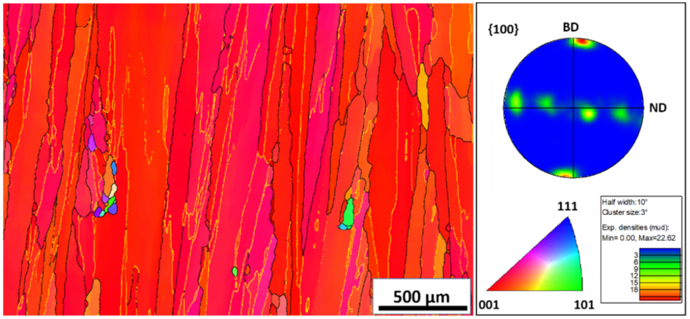
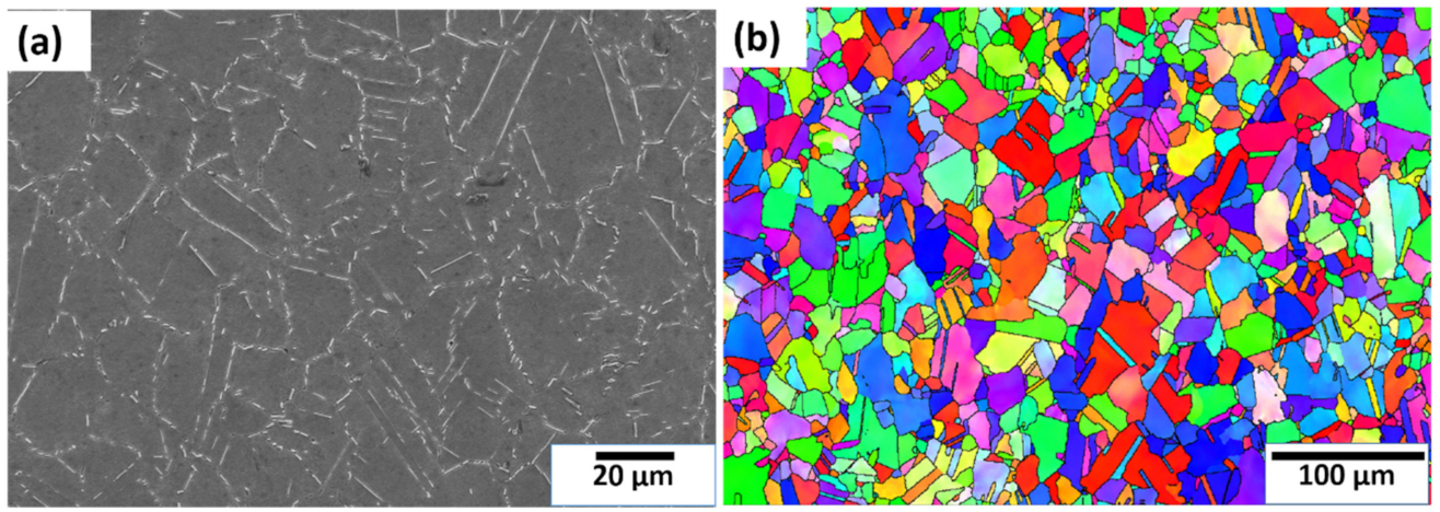
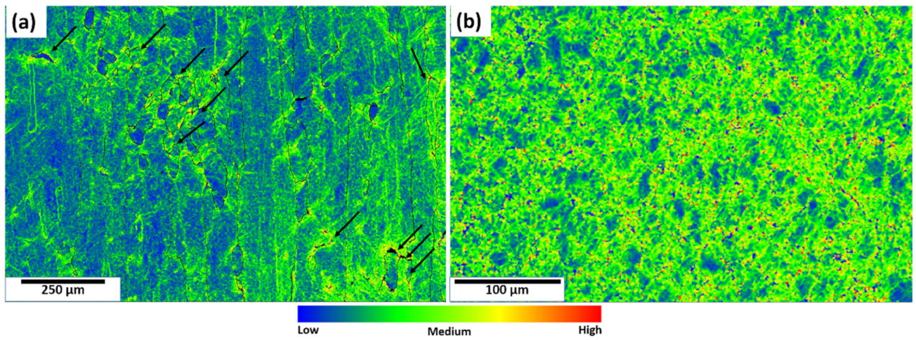
  • The IN718 fabricated using the EBM process exhibited a columnar-grained structure with a strong <100> crystal orientation along the building direction.
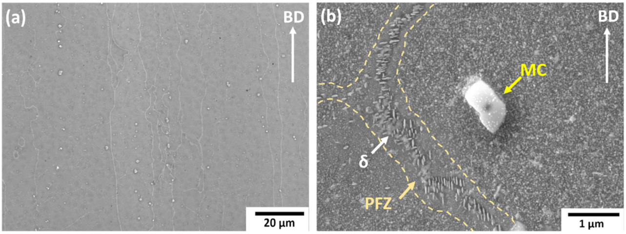
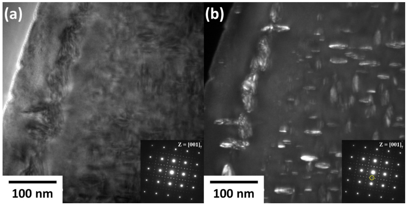
  • The presence of disc-shaped δ precipitates at the grain boundary and the higher γ” size in the grain interior are the main reasons for the higher creep life observed in the DA specimen.
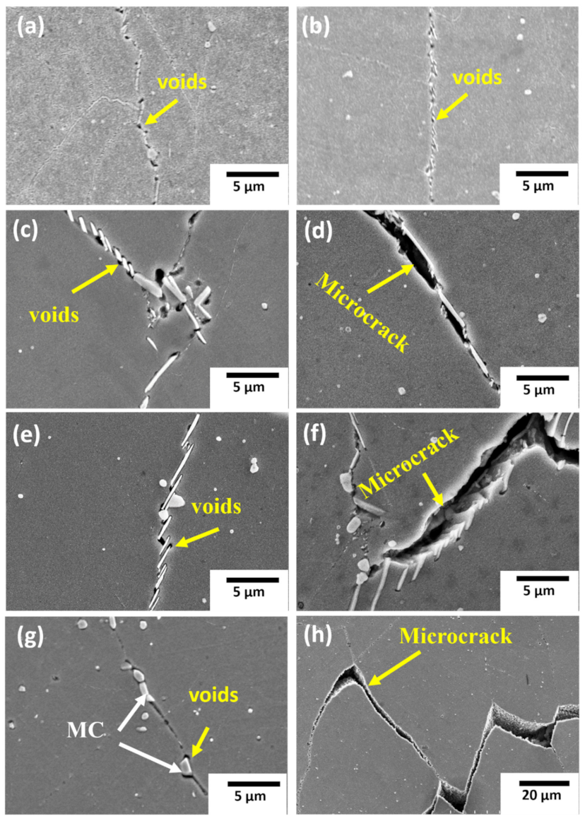
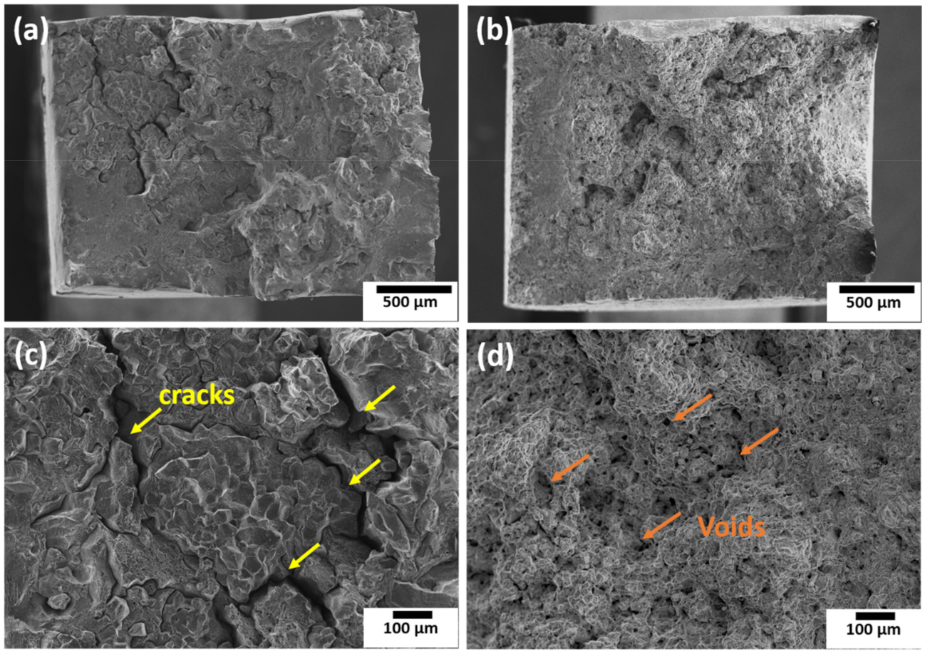
  • The creep void formation and coalescence around the needle-shaped δ precipitates at the grain boundary lead to intergranular fracture in the STA and HSA specimens
  • The lower amount of oxygen, the higher twin boundary fraction, and the homogeneous grain structure are the reasons for the superior creep properties of the C&W specimen compared to the EBM specimen.

Author Contributions

Conceptualization, T.N.P. and K.K.; data curation, T.N.P., S.B. and Y.-L.K., funding acquisition, K.K.; investigation, T.N.P. and S.B.; methodology, T.N.P. and S.B.; supervision, K.K.; writing—original draft, T.N.P.; writing—review and editing, K.K. All authors have read and agreed to the published version of the manuscript.

Funding

The authors are grateful to the AMADA Foundation (AF-2018222-B3) and the ALCA Program of the Japan Science and Technology Agency, JST (grant number JPMJAL1605) for funding.

Institutional Review Board Statement

Not applicable.

Informed Consent Statement

Not applicable.

Data Availability Statement

The data presented in this study are available on request from the corresponding author.

Conflicts of Interest

The authors declare no conflict of interest.

References

  1. Chaturvedi, M.C.; Han, Y.-F. Strengthening mechanisms in Inconel 718 superalloy. Met. Sci. 1983, 17, 145–149. [Google Scholar] [CrossRef]
  2. Brooks, J.; Bridges, P. Metallurgical Stability of Inconel Alloy 718. Superalloys 1988, 88, 33–42. [Google Scholar] [CrossRef]
  3. Moll, J.H.; Maniar, G.N.; Muzyka, D.R. Heat treatment of 706 alloy for optimum 1200 °F stress-rupture properties. Met. Mater. Trans. A 1971, 2, 2153–2160. [Google Scholar] [CrossRef]
  4. Lingenfelter, A. Welding of Inconel Alloy 718: A Historical Overview. Superalloys 1989, 718, 673–683. [Google Scholar]
  5. Kakehi, K.; Banoth, S.; Kuo, Y.-L.; Hayashi, S. Effect of yttrium addition on creep properties of a Ni-base superalloy built up by selective laser melting. Scr. Mater. 2020, 183, 71–74. [Google Scholar] [CrossRef]
  6. Gong, X.; Anderson, T.; Chou, K. Review on powder-based electron beam additive manufacturing technology. Manuf. Rev. 2014, 1, 2. [Google Scholar] [CrossRef]
  7. Sochalski-Kolbus, L.M.; Payzant, E.; Cornwell, P.A.; Watkins, T.; Babu, S.; Dehoff, R.; Lorenz, M.; Ovchinnikova, O.; Duty, C. Comparison of Residual Stresses in Inconel 718 Simple Parts Made by Electron Beam Melting and Direct Laser Metal Sintering. Met. Mater. Trans. A 2015, 46, 1419–1432. [Google Scholar] [CrossRef]
  8. Murr, L.; Gaytan, S.; Ceylan, A.; Martinez, E.; Martinez, J.; Hernandez, D.; Machado, B.; Ramirez, D.; Medina, F.; Collins, S. Characterization of titanium aluminide alloy components fabricated by additive manufacturing using electron beam melting. Acta Mater. 2010, 58, 1887–1894. [Google Scholar] [CrossRef]
  9. Loeber, L.; Biamino, S.; Ackelid, U.; Sabbadini, S.; Epicoco, P.; Fino, P.; Eckert, J. Comparison of selective laser and electron beam melted titanium aluminides. In Proceedings of the 22nd Annual International Solid Freeform Fabrication Symposium—An Additive Manufacturing Conference SFF, Austin, TX, USA, 8–10 August 2011; pp. 547–556. [Google Scholar]
  10. Strondl, A.; Palm, M.; Gnauk, J.; Frommeyer, G. Microstructure and mechanical properties of nickel based superalloy IN718 produced by rapid prototyping with electron beam melting (EBM). Mater. Sci. Technol. 2011, 27, 876–883. [Google Scholar] [CrossRef]
  11. Goel, S.; Sittiho, A.; Charit, I.; Klement, U.; Joshi, S. Effect of post-treatments under hot isostatic pressure on microstructural characteristics of EBM-built Alloy 718. Addit. Manuf. 2019, 28, 727–737. [Google Scholar] [CrossRef]
  12. Nandwana, P.; Kirka, M.; Okello, A.; Dehoff, R. Electron beam melting of Inconel 718: Effects of processing and post-processing. Mater. Sci. Technol. 2017, 34, 612–619. [Google Scholar] [CrossRef]
  13. Deng, D.; Moverare, J.; Peng, R.L.; Söderberg, H. Microstructure and anisotropic mechanical properties of EBM manufactured Inconel 718 and effects of post heat treatments. Mater. Sci. Eng. A 2017, 693, 151–163. [Google Scholar] [CrossRef]
  14. Kirka, M.M.; Medina, F.; Dehoff, R.; Okello, A. Mechanical behavior of post-processed Inconel 718 manufactured through the electron beam melting process. Mater. Sci. Eng. A 2017, 680, 338–346. [Google Scholar] [CrossRef] [Green Version]
  15. Sun, S.-H.; Koizumi, Y.; Saito, T.; Yamanaka, K.; Li, Y.-P.; Cui, Y.; Chiba, A. Electron beam additive manufacturing of Inconel 718 alloy rods: Impact of build direction on microstructure and high-temperature tensile properties. Addit. Manuf. 2018, 23, 457–470. [Google Scholar] [CrossRef]
  16. Helmer, H.; Bauereiß, A.; Singer, R.; Körner, C. Grain structure evolution in Inconel 718 during selective electron beam melting. Mater. Sci. Eng. A 2016, 668, 180–187. [Google Scholar] [CrossRef]
  17. Yu, H.; Hayashi, S.; Kakehi, K.; Kuo, Y.-L. Study of Formed Oxides in IN718 Alloy during the Fabrication by Selective Laser Melting and Electron Beam Melting. Metals 2018, 9, 19. [Google Scholar] [CrossRef] [Green Version]
  18. Im, S.-Y.; Jun, S.-Y.; Lee, J.-W.; Lee, J.-H.; Lee, B.-S.; Lee, H.-J.; Hong, H.-U. Unidirectional columnar microstructure and its effect on the enhanced creep resistance of selective electron beam melted Inconel 718. J. Alloy. Compd. 2020, 817, 153320. [Google Scholar] [CrossRef]
  19. Sass, V.; Glatzel, U.; Feller-Kniepmeier, M. Anisotropic creep properties of the nickel-base superalloy CMSX-4. Acta Mater. 1996, 44, 1967–1977. [Google Scholar] [CrossRef]
  20. Kakehi, K. Tension/compression asymmetry in creep behavior of a Ni-based superalloy. Scr. Mater. 1999, 41, 461–465. [Google Scholar] [CrossRef]
  21. Caron, P.; Ohta, Y.; Nakagawa, Y.; Khan, T. Creep Deformation Anisotropy in Single Crystal Superalloys. Superalloys 1988, 1988, 215–224. [Google Scholar]
  22. Mackay, R.A.; Maier, R.D. The influence of orientation on the stress rupture properties of nickel-base superalloy single crystals. Met. Mater. Trans. A 1982, 13, 1747–1754. [Google Scholar] [CrossRef]
  23. Niang, A.; Viguier, B.; Lacaze, J. Some features of anisothermal solid-state transformations in alloy. Mater. Charact. 2010, 61, 525–534. [Google Scholar] [CrossRef] [Green Version]
  24. Sundararaman, M.; Mukhopadhyay, P.; Banerjee, S. Precipitation of the δ-Ni3Nb phase in two nickel base superalloys. Met. Mater. Trans. A 1988, 19, 453–465. [Google Scholar] [CrossRef]
  25. Han, Y.; Chaturvedi, M. Steady state creep deformation of superalloy inconel. Mater. Sci. Eng. 1987, 89, 25–33. [Google Scholar] [CrossRef]
  26. Langdon, T.G. Grain boundary sliding as a deformation mechanism during creep. Philos. Mag. 1970, 22, 689–700. [Google Scholar] [CrossRef]
  27. Han, Y.-F.; Deb, P.; Chaturvedi, M.C. Coarsening behaviour of γ″- and γ′-particles in Inconel alloy. Met. Sci. 1982, 16, 555–562. [Google Scholar] [CrossRef]
  28. Azadian, S. Aspects of precipitation in alloy Inconel 718. Ph.D. Thesis, Luleå University of Technology, Luleå, Sweden, 2004; pp. 51–67. Available online: http://www.diva-portal.org/smash/get/diva2:999089/FULLTEXT01.pdf (accessed on 2 March 2022).
  29. Ansell, G.S.; Weertman, S. Creep of a Dispersion-Hardened Aluminum Alloy; Naval Research Lab.: Washington, DC, USA, 1958; p. 838. [Google Scholar]
  30. Chen, W.; Chaturvedi, M. The effect of grain boundary precipitates on the creep behavior of Inconel 718. Mater. Sci. Eng. A 1994, 183, 81–89. [Google Scholar] [CrossRef]
  31. Chen, W.; Chaturvedi, M. Dependence of Creep Fracture of Inconel 718 on Grain Boundary Precipitates. Acta Mater. 1997, 45, 2735–2746. [Google Scholar] [CrossRef]
  32. Kuo, C.-M.; Yang, Y.-T.; Bor, H.-Y.; Wei, C.-N.; Tai, C.-C. Aging effects on the microstructure and creep behavior of Inconel 718 superalloy. Mater. Sci. Eng. A 2009, 510–511, 289–294. [Google Scholar] [CrossRef]
  33. Son, K.-T.; Phan, T.; Levine, L.; Kim, K.-S.; Lee, K.-A.; Ahlfors, M.; Kassner, M. The creep and fracture properties of additively manufactured Inconel. Materials 2021, 15, 101021. [Google Scholar] [CrossRef]
  34. Son, K.; Kassner, M.E.; Lee, K.A. The Creep Behavior of Additively Manufactured Inconel 625. Adv. Eng. Mater. 2020, 22, 1900543. [Google Scholar] [CrossRef]
  35. Rao, G.A.; Srinivas, M.; Sarma, D. Effect of oxygen content of powder on microstructure and mechanical properties of hot isostatically pressed superalloy Inconel. Mater. Sci. Eng. A 2006, 435–436, 84–99. [Google Scholar] [CrossRef]
  36. Nagahari, T.; Nagoya, T.; Kakehi, K.; Sato, N.; Nakano, S. Microstructure and Creep Properties of Ni-Base Superalloy IN718 Built up by Selective Laser Melting in a Vacuum Environment. Metals 2020, 10, 362. [Google Scholar] [CrossRef] [Green Version]
  37. Gessinger, G.H.; Bomford, M.J. Powder Metallurgy of Superalloys. Int. Met. Rev. 1974, 19, 51–76. [Google Scholar] [CrossRef]
  38. Woodford, D.; Bricknell, R. Environmental Embrittlement of High Temperature Alloys by Oxygen. Treatise Mater. Sci. Technol. 1983, 25, 157–199. [Google Scholar]
  39. Huang, Z.; Iwashita, C.; Chou, I.; Wei, R.P. Environmentally assisted, sustained-load crack growth in powder metallurgy nickel-based superalloys. Met. Mater. Trans. A 2002, 33, 1681–1687. [Google Scholar] [CrossRef]
  40. Hayes, R.; Smith, D.; Wanner, E.; Earthman, J. Effect of environment on the rupture behavior of alloys 909 and 718. Mater. Sci. Eng. A 1994, 177, 43–53. [Google Scholar] [CrossRef]
Figure 1. EBSD–IPF map of as-built EBM IN718 specimen with <001> orientation to the building direction. In the map, the low-angle grain boundaries (LABs) (2° ≤ θ < 10°) and high-angle grain boundaries (HABs) (10° ≤ θ) are indicated by yellow and black lines, respectively. (BD: Building Direction, ND: Normal Direction).
Metals 12 00446 g001
Figure 2. EPMA element maps showing the formation of Al2O3 and TiN in the EBM IN718 as-built specimen along the building direction [17] (BSE: Backscattered Electrons image).
Metals 12 00446 g002
Figure 3. STEM image showing “core-shell” structures of Al2O3 and (Ti,Nb)C and the corresponding WDS elemental maps of C, O, Al, Cr, Ni, Ti, Nb, and Mo of the as-built EBM IN718.
Metals 12 00446 g003
Figure 4. SEM micrographs showing grain morphology and precipitation along the grain boundary in as-built EBM IN718 parallel to the building direction, (a) at lower magnification and (b) at higher magnification. (BD: Building Direction, PFZ: Precipitate Free Zone).
Metals 12 00446 g004
Figure 5. TEM images of as-built specimen were taken from the [001] zone axis, showing nano-scale γ’/γ” precipitates—(a) bright-field image, (b) dark-field image.
Metals 12 00446 g005
Figure 6. EBSD–IPF maps of post-heat-treated specimens along the building direction: (a) DA, (b) STA, (c) HSA, (d) HA. The low-angle grain boundaries (LABs) (2° ≤ θ < 10°) and high-angle grain boundaries (HABs) (10° ≤ θ) are indicated by yellow and black lines, respectively.
Metals 12 00446 g006
Figure 7. SEM micrographs showing grain boundary δ phase morphology and γ’/γ” precipitates for various heat treatments: (a,b) DA, (c,d) SA, (e,f) HSA, (g,h) HA. The black arrows indicate the building direction.
Metals 12 00446 g007
Figure 8. Plots showing creep properties of EBM IN718 for as-built and various post-heat-treated specimens along the building direction; (a) depicts the creep curves at 650 °C and 650 MPa, and (b) shows the correlations between creep rate and time.
Metals 12 00446 g008
Figure 9. (a) TEM micrographs showing shearing of coarse γ” precipitates by dislocations after the creep test of AB specimen and (b,c) the formation of stacking faults and micro-twins after the creep test for the DA specimen.
Metals 12 00446 g009
Figure 10. Relationship between creep life and steady rate creep rate for various heat treated specimens.
Metals 12 00446 g010
Figure 11. SEM micrographs of cross-sections of crept specimens showing voids and microcracks at grain boundary δ precipitates of (a) AB, (b) DA, (c,d) SA, and (e,f) HSA, and at grain boundary carbides of (g,h) HA.
Metals 12 00446 g011
Figure 12. (a) SEM micrograph of C&W IN718 showing precipitates and (b) EBSD orientation map showing random orientation.
Metals 12 00446 g012
Figure 13. SEM micrographs showing fracture surface morphologies of specimens after the creep test for (a,c) the EBM IN718 STA specimen and (b,d) the C&W IN718 specimen.
Metals 12 00446 g013
Figure 14. Local misorientation maps after creep test for (a) the EBM IN718 specimen and (b) the C&W IN718 specimen. The black arrows indicate fine grains.
Metals 12 00446 g014
Table 1. Nominal chemical composition of EBM 718 powders (mass %).
IN718NiCrNbMoTiAlCoCuCSiMnOFe
EBM52.5919.34.893.041.070.540.010.040.030.050.17142 ppmBal.
C&W53.1618.85.012.990.920.600.280.030.040.070.027 ppmBal.
EBM: Electron Beam Melting; C&W: Cast and Wrought.
Table 2. Details of the heat-treatment conditions for the EBM IN718 and corresponding nomenclature.
SpecimenSolutionization/HomogenizationAging
AB--
DA-720 °C/8 h/FC + 620 °C/10 h/AC
SA980 °C/1 h/AC720 °C/8 h/ FC + 620 °C/10 h/AC
HSA1095 °C/1 h/AC + 955 °C/6 h/AC720 °C/8 h/FC + 620 °C/10 h/AC
HA1095 °C/1 h/AC720 °C/8 h/FC + 620 °C/10 h/AC
C&W980 °C/1 h/AC720 °C/8 h/FC + 620 °C/10 h/AC
Nomenclature: AB: as-built, DA: direct-aged, SA: solutionized and aged, HSA: homogenized + solutionized and aged, HA: homogenized and aged, C&W: cast and wrought, FC: furnace-cooled, AC: air-cooled.
Table 3. The creep properties of as-built and various post-heat-treated specimens presented in Figure 8.
SpecimenCreep Life (h)Creep Elongation (%)Minimum Creep Rate (10−8 s−1)
AB296.784.200.50
DA617.054.050.15
SA124.706.054.96
HSA116.467.165.52
HA238.629.641.01
C&W787.466.400.23
Publisher’s Note: MDPI stays neutral with regard to jurisdictional claims in published maps and institutional affiliations.

