
Mechanical Aspects of Nonhomogeneous Deformation of Aluminum Single Crystals under Compression along [100] and [110] Directions


 , ,
, ,
Abstract
:1. Introduction
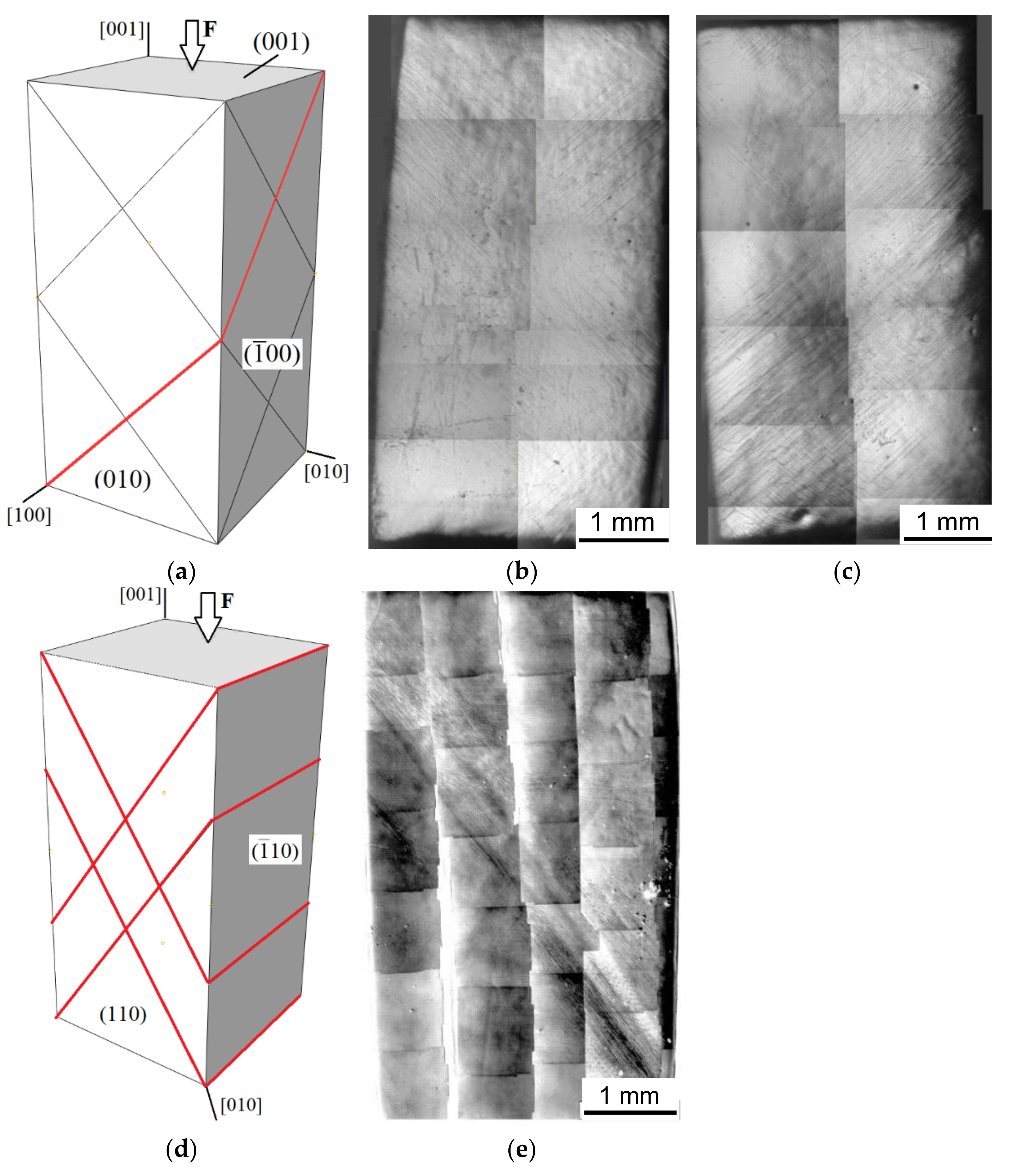
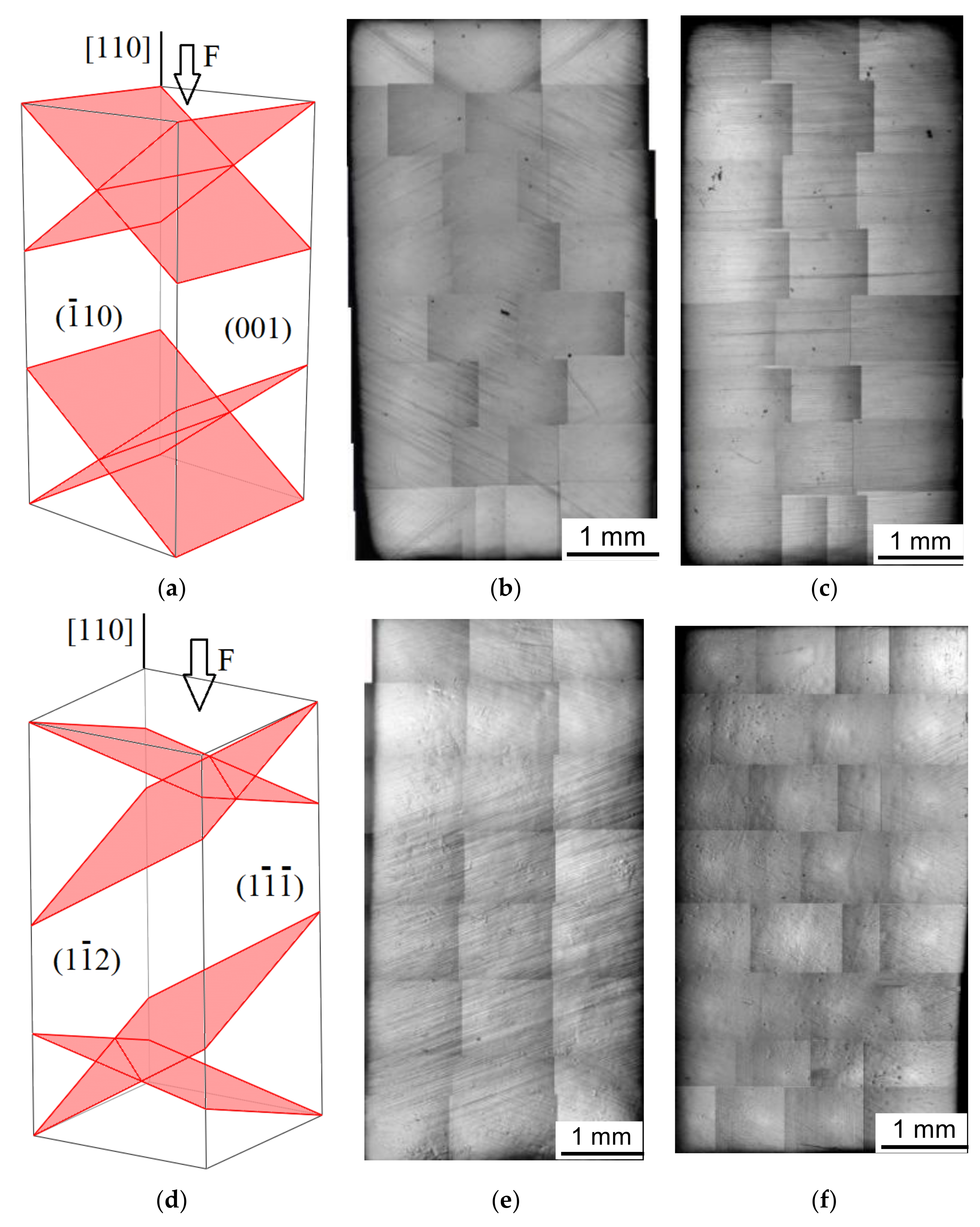
2. Experimental
3. Numerical Model
3.1. Boundary-Value Problem, Geometry, and Loading Conditions
3.2. Constitutive Model
3.3. Numerical Implementation
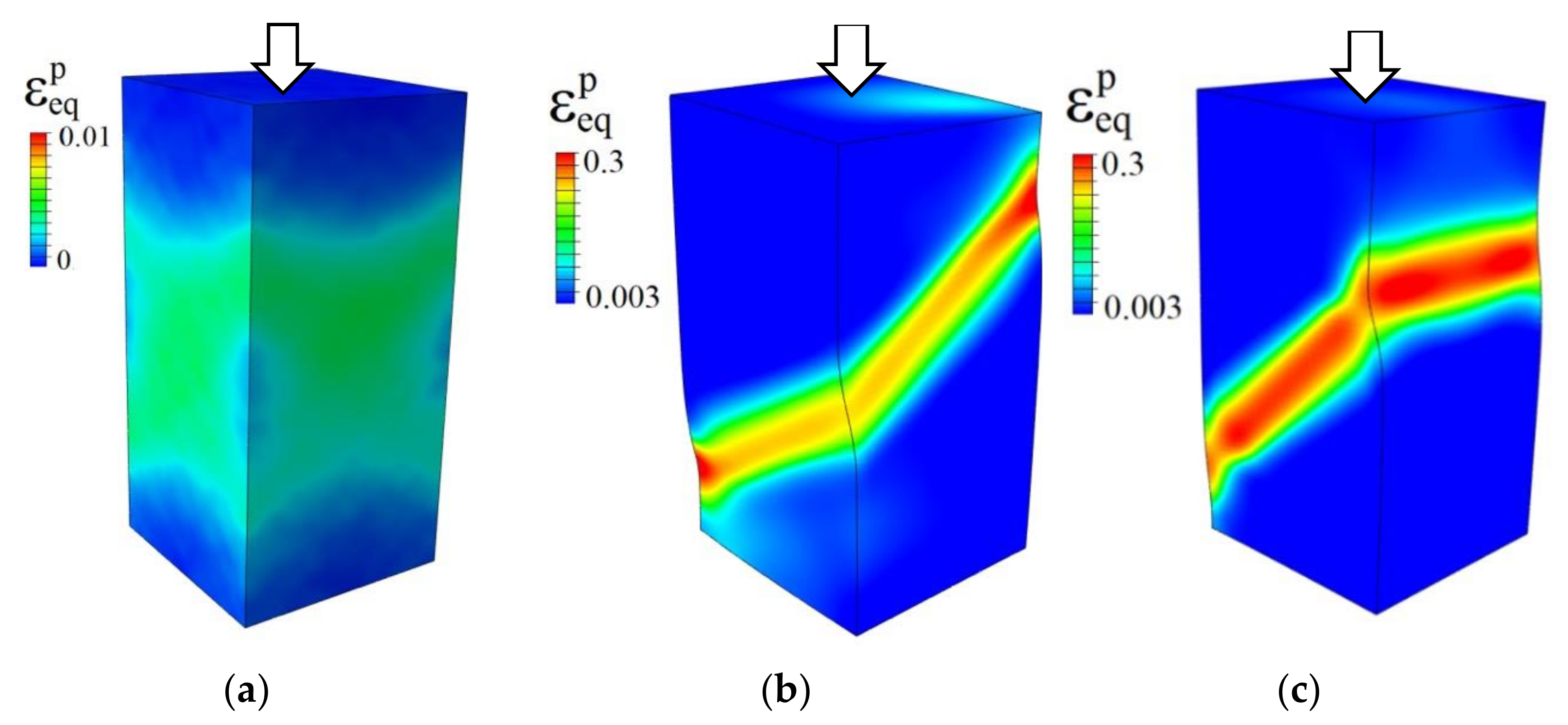
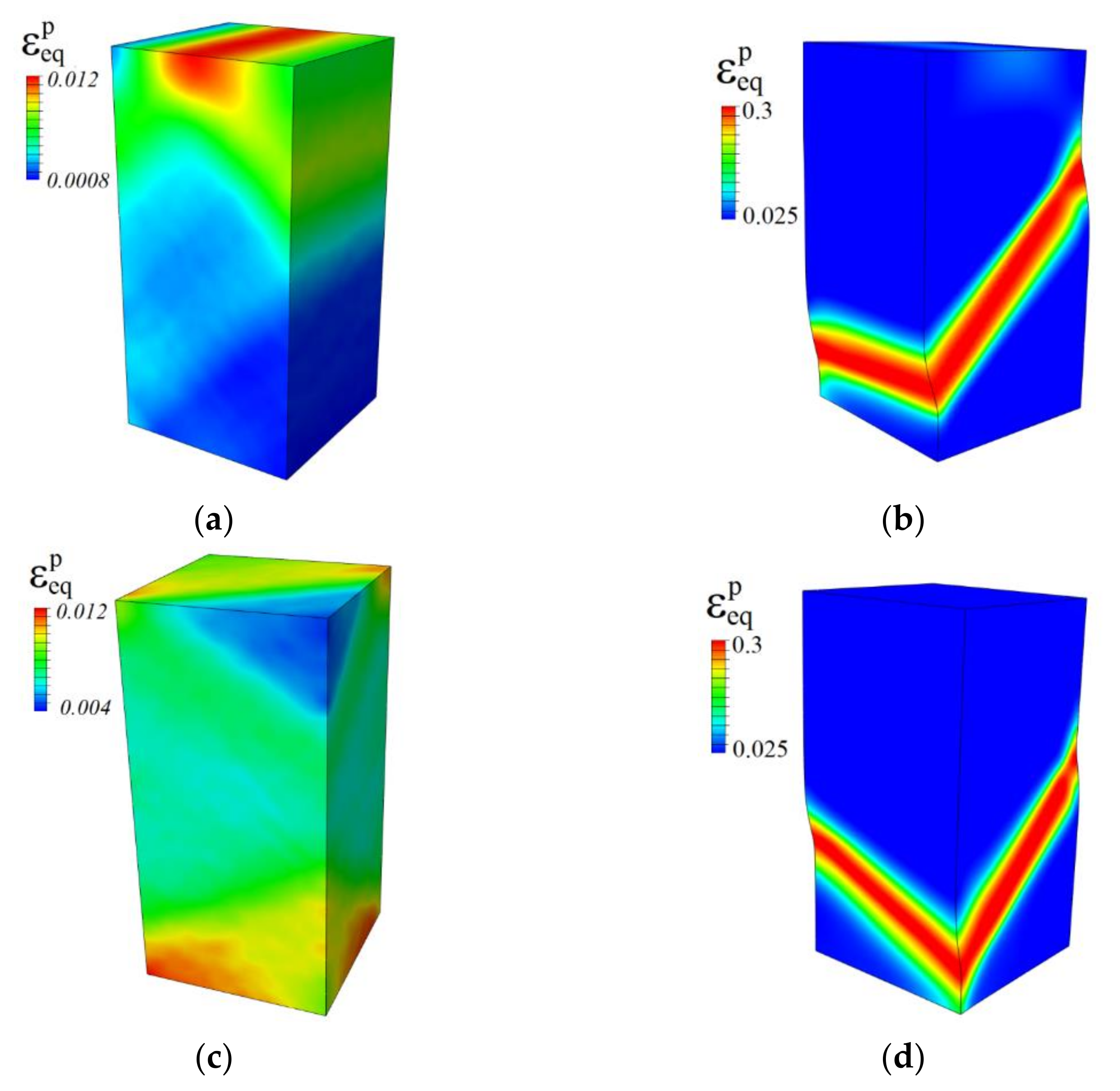
4. Calculation Results
4.1. Perfect Plasticity
4.2. Strain-Hardening Effects
5. Discussion
6. Conclusions
Supplementary Materials
Author Contributions
Funding
Institutional Review Board Statement
Informed Consent Statement
Data Availability Statement
Conflicts of Interest
References
- Lychagin, D.V.; Dmitriev, A.I.; Nikonov, A.Y.; Alfyorova, E.A. Crystallographic and Geometric Factors in the Shear Development in <001> FCC Single Crystals: Molecular Dynamics Simulation and Experimental Study. Crystals 2020, 10, 666. [Google Scholar] [CrossRef]
- Honeycomb, R.W.K. The Plastic Deformation of Metals; Edward Arnold: London, UK, 1968. [Google Scholar]
- Rice, J.R. Inelastic Constitutive Relations for Solids: An Internal-Variable Theory and Its Application to Metal Plasticity. J. Mech. Phys. Solids 1971, 19, 433–455. [Google Scholar] [CrossRef]
- Sachs, G. Zur Ableitung einer Fließbedingung. Z. Des Ver. Dtsch. Ing. 1928, 72, 734–736. [Google Scholar] [CrossRef]
- Taylor, G.I. Plastic Strain in Metals. J. Inst. Met. 1938, 62, 307–324. [Google Scholar]
- Bishop, J.F.W.; Hill, R. A Theory of the Plastic Distortion of a Polycrystalline Aggregate under Combined Stresses. Lond. Edinb. Dublin Philos. Mag. J. Sci. 1951, 42, 414–427. [Google Scholar] [CrossRef]
- Leffers, T. A Modified Sachs Approach to the Plastic Deformation of Polycrystals as a Realistic Alternative to the Taylor Model. In Strength of Metals and Alloys: Proceedings of the 5th International Conference; Pergamon Press: Oxford, UK, 1979; pp. 769–774. [Google Scholar] [CrossRef]
- van Houtte, P. On the Equivalence of the Relaxed Taylor Theory and the Bishop-Hill Theory for Partially Constrained Plastic Deformation of Crystals. Mater. Sci. Eng. 1982, 55, 69–77. [Google Scholar] [CrossRef]
- Kocks, U.F.; Chandra, H. Slip Geometry in Partially Constrained Deformation. Acta Metall. 1982, 30, 695–709. [Google Scholar] [CrossRef]
- Peirce, D.; Asaro, R.J.; Needleman, A. An Analysis of Nonuniform and Localized Deformation in Ductile Single Crystals. Acta Metall. 1982, 30, 1087–1119. [Google Scholar] [CrossRef]
- Becker, R.; Butler, J.F.; Hu, H.; Lalli, L.A. Analysis of an Aluminum Single Crystal with Unstable Initial Orientation (001) [110] in Channel Die Compression. Metall. Trans. A 1991, 22, 45–58. [Google Scholar] [CrossRef]
- Cereceda, D.; Diehl, M.; Roters, F.; Raabe, D.; Perlado, J.M.; Marian, J. Unraveling the Temperature Dependence of the Yield Strength in Single-Crystal Tungsten Using Atomistically-Informed Crystal Plasticity Calculations. Int. J. Plast. 2016, 78, 242–265. [Google Scholar] [CrossRef] [Green Version]
- Ryś, M.; Petryk, H. Gradient Crystal Plasticity Models with a Natural Length Scale in the Hardening Law. Int. J. Plast. 2018, 111, 168–187. [Google Scholar] [CrossRef]
- Senas, D.C. Multiscale Modeling of the Plastic Behaviour in Single Crystal Tungsten: From Atomistic to Crystal Plasticity Simulations. Ph.D. Thesis, Polytechnic University of Madrid, Madrid, Spain, 2015. [Google Scholar]
- Emelianova, E.S.; Romanova, V.A.; Balokhonov, R.R.; Pisarev, M.; Zinovieva, O.S. A Numerical Study of the Contribution of Different Slip Systems to the Deformation Response of Polycrystalline Titanium. Phys. Mesomech. 2021, 24, 166–177. [Google Scholar] [CrossRef]
- Jalili, M.; Soltani, B. Investigation the Micromechanisms of Strain Localization Formation in AZ31 Mg Alloy: A Mesoscale 3D Full-Field Crystal Plasticity Computational Homogenization Study. Eur. J. Mech.-A/Solids 2020, 80, 103903. [Google Scholar] [CrossRef]
- Roters, F.; Eisenlohr, P.; Hantcherli, L.; Tjahjanto, D.D.; Bieler, T.R.; Raabe, D. Overview of Constitutive Laws, Kinematics, Homogenization and Multiscale Methods in Crystal Plasticity Finite-Element Modeling: Theory, Experiments, Applications. Acta Mater. 2010, 58, 1152–1211. [Google Scholar] [CrossRef]
- Zhao, Z.; Ramesh, M.; Raabe, D.; Cuitiño, A.M.; Radovitzky, R. Investigation of Three-Dimensional Aspects of Grain-Scale Plastic Surface Deformation of an Aluminum Oligocrystal. Int. J. Plast. 2008, 24, 2278–2297. [Google Scholar] [CrossRef]
- Forest, S.; Rubin, M.B. A Rate-Independent Crystal Plasticity Model with a Smooth Elastic–Plastic Transition and No Slip Indeterminacy. Eur. J. Mech.-A/Solids 2016, 55, 278–288. [Google Scholar] [CrossRef]
- Roters, F.; Wang, Y.; Kuo, J.C.; Raabe, D. Comparison of Single Crystal Simple Shear Deformation Experiments with Crystal Plasticity Finite Element Simulations. Adv. Eng. Mater. 2004, 6, 653–656. [Google Scholar] [CrossRef]
- Khan, A.S.; Liu, J.; Yoon, J.W.; Nambori, R. Strain Rate Effect of High Purity Aluminum Single Crystals: Experiments and Simulations. Int. J. Plast. 2015, 67, 39–52. [Google Scholar] [CrossRef]
- Trusov, P.V.; Yanz, A.Y.; Teplyakova, L.A. Direct Crystal Elastoviscoplasticity Model: An Application to the Study of Single Crystal Deformation. Phys. Mesomech. 2019, 22, 275–286. [Google Scholar] [CrossRef]
- Schacht, T.; Untermann, N.; Steck, E. The Influence of Crystallographic Orientation on the Deformation Behaviour of Single Crystals Containing Microvoids. Int. J. Plast. 2003, 19, 1605–1626. [Google Scholar] [CrossRef]
- Wang, H.; Lu, C.; Tieu, K.; Liu, Y. A Crystal Plasticity FE Study of Macro- and Micro-Subdivision in Aluminium Single Crystals {001}<110> Multi-Pass Rolled to a High Reduction. J. Mater. Sci. Technol. 2021, 76, 231–246. [Google Scholar] [CrossRef]
- Romanova, V.; Zinovieva, O.; Balokhonov, R.; Dymnich, E.; Moskvichev, E.; Filippov, A.; Lychagin, D. Effects of the Grain Shape and Crystallographic Texture on the Grain-Scale Mechanical Behavior of Additively Manufactured Aluminum Alloys. Addit. Manuf. 2021, 48, 102415. [Google Scholar] [CrossRef]
- Romanova, V.; Balokhonov, R.; Zinovieva, O.; Emelianova, E.; Dymnich, E.; Pisarev, M.; Zinoviev, A. Micromechanical Simulations of Additively Manufactured Aluminum Alloys. Comput. Struct. 2021, 244, 106412. [Google Scholar] [CrossRef]
- Jayaprakash, S.; Siva Chandran, S.; Sathish, T.; Gugulothu, B.; Ramesh, R.; Sudhakar, M.; Subbiah, R. Effect of Tool Profile Influence in Dissimilar Friction Stir Welding of Aluminium Alloys (AA5083 and AA7068). Adv. Mater. Sci. Eng. 2021, 2021, 7387296. [Google Scholar] [CrossRef]
- Balokhonov, R.; Romanova, V.; Batukhtina, E.; Martynov, S.; Zinoviev, A.; Zinovieva, O. A Mesomechanical Analysis of the Stress–Strain Localisation in Friction Stir Welds of Polycrystalline Aluminium Alloys. Meccanica 2016, 51, 319–328. [Google Scholar] [CrossRef]
- Romanova, V.; Balokhonov, R.; Zinovieva, O. A Micromechanical Analysis of Deformation-Induced Surface Roughening in Surface-Modified Polycrystalline Materials. Meccanica 2016, 51, 359–370. [Google Scholar] [CrossRef]
- Bryhni Dæhli, L.E.; Faleskog, J.; Børvik, T.; Hopperstad, O.S. Unit Cell Simulations and Porous Plasticity Modelling for Strongly Anisotropic FCC Metals. Eur. J. Mech.-A/Solids 2017, 65, 360–383. [Google Scholar] [CrossRef]
- Teplyakova, L.A.; Bespalova, I.V.; Lychagin, D.V. Spatial Organization of Deformation in Aluminum [1ī2] Single Crystals in Compression. Phys. Mesomech. 2009, 12, 166–174. [Google Scholar] [CrossRef]
- Lychagin, D.V. Fragmentation of Plastically Deformed FCC Metallic Materials. Phys. Mesomech. 2006, 9, 95–105. [Google Scholar]
- Teplyakova, L.A.; Bespalova, I.V.; Lychagin, D.V. Laws of Deformation Macrolocalization in Aluminum Single Crystals with the Orientation of the Compression Axis [110]. Phys. Mesomech. 2004, 7, 63–78. [Google Scholar]
- Teplyakova, L.A.; Lychagin, D.V.; Kozlov, E.V. Shear Localization in Deformed Al Single Crystals with a Compression Axis Orientation [001]. Phys. Mesomech. 2003, 6, 19. [Google Scholar]
- Wonsiewicz, B.C.; Chin, G.Y. Inhomogeneity of Plastic Flow in Constrained Deformation. Metall. Trans. 1970, 1, 57–61. [Google Scholar] [CrossRef]
- Magid, K.R.; Florando, J.N.; Lassila, D.H.; Leblanc, M.M.; Tamura, N.; Morris, J.W., Jr. Mapping Mesoscale Heterogeneity in the Plastic Deformation of a Copper Single Crystal. Philos. Mag. 2009, 89, 77–107. [Google Scholar] [CrossRef] [Green Version]
- Ha, S.; Kim, K.T. Heterogeneous Deformation of Al Single Crystal: Experiments and FInite Element Analysis. Math. Mech. Solids 2011, 16, 652–661. [Google Scholar] [CrossRef]
- Lychagin, D.V.; Tarasov, S.Y.; Chumaevskii, A.V.; Alfyorova, E.A. Macrosegmentation and Strain Hardening Stages in Copper Single Crystals under Compression. Int. J. Plast. 2015, 69, 36–53. [Google Scholar] [CrossRef]
- Paul, H.; Maurice, C.; Driver, J.H. Microstructure and Microtexture Evolution during Strain Path Changes of an Initially Stable Cu Single Crystal. Acta Mater. 2010, 58, 2799–2813. [Google Scholar] [CrossRef]
- Jia, N.; Eisenlohr, P.; Roters, F.; Raabe, D.; Zhao, X. Orientation Dependence of Shear Banding in Face-Centered-Cubic Single Crystals. Acta Mater. 2012, 60, 3415–3434. [Google Scholar] [CrossRef]
- Lychagin, D.V.; Teplyakova, L.A. The Primary Macrofragmentation of Shear in Compressed Aluminum Single Crystals. Tech. Phys. Lett. 2003, 29, 516–518. [Google Scholar] [CrossRef]
- Basson, F.; Driver, J.H. Deformation Banding Mechanisms during Plane Strain Compression of Cube-Oriented f.c.c. Crystals. Acta Mater. 2000, 48, 2101–2115. [Google Scholar] [CrossRef]
- Petryk, H.; Kursa, M. The Energy Criterion for Deformation Banding in Ductile Single Crystals. J. Mech. Phys. Solids 2013, 61, 1854–1875. [Google Scholar] [CrossRef]
- Teplyakova, L.A.; Kozlov, E.V. Formation of Scale Structural Levels of Plastic Deformation Localization in Metal Single Crystals. I. Macrolevel. Phys. Mesomech. 2006, 9, 53–62. [Google Scholar]
- Akef, A.; Driver, J.H. Orientation Splitting of Cube-Oriented Face-Centred Cubic Crystals in Plane Strain Compression. Mater. Sci. Eng. A 1991, 132, 245–255. [Google Scholar] [CrossRef]
- Wert, J.A.; Liu, Q.; Hansen, N. Dislocation Boundary Formation in a Cold-Rolled Cube-Oriented Al Single Crystal. Acta Mater. 1997, 45, 2565–2576. [Google Scholar] [CrossRef]
- Harewood, F.J.; McHugh, P.E. Investigation of Finite Element Mesh Independence in Rate Dependent Materials. Comput. Mater. Sci. 2006, 37, 442–453. [Google Scholar] [CrossRef]
- Romanova, V.A.; Balokhonov, R.R.; Batukhtina, E.E.; Emelianova, E.S.; Sergeev, M.V. On the Solution of Quasi-Static Micro- and Mesomechanical Problems in a Dynamic Formulation. Phys. Mesomech. 2019, 22, 296–306. [Google Scholar] [CrossRef]
- Romanova, V.; Balokhonov, R.; Emelianova, E.; Zinovieva, O.; Zinoviev, A. Microstructure-Based Simulations of Quasistatic Deformation Using an Explicit Dynamic Approach. Facta Univ. Ser. Mech. Eng. 2019, 17, 243–254. [Google Scholar] [CrossRef]
- Brandes, E.A.; Brook, G.B. (Eds.) Smithells Metals Reference Book, 7th ed.; Butterworth-Heinemann: Oxford, UK, 1992. [Google Scholar]
- Zecevic, M.; Cawkwell, M.J.; Ramos, K.J.; Luscher, D.J. Simulating Knoop Hardness Anisotropy of Aluminum and β-HMX with a Crystal Plasticity Finite Element Model. Int. J. Plast. 2021, 144, 103045. [Google Scholar] [CrossRef]
- Meng, C.; Wei, H.; Chen, H.; Liu, Y. Modeling Plasticity of Cubic Crystals Using a Nonlocal Lattice Particle Method. Comput. Methods Appl. Mech. Eng. 2021, 385, 114069. [Google Scholar] [CrossRef]
- Polyanskiy, V.A.; Belyaev, A.K.; Grishchenko, A.I.; Lobachev, A.M.; Modestov, V.S.; Pivkov, A.V.; Tretyakov, D.A.; Shtukin, L.V.; Semenov, A.S.; Yakovlev, Y.A. Finite Element Simulation of Chessboard Strain Localization in View of Statistical Spreads in Polycrystal Grain Parameters. Phys. Mesomech. 2019, 22, 188–194. [Google Scholar] [CrossRef]
- Petryk, H. General Conditions for Uniqueness in Materials with Multiple Mechanisms of Inelastic Deformation. J. Mech. Phys. Solids 2000, 48, 367–396. [Google Scholar] [CrossRef]
- Kunitsyna, T.S.; Teplyakova, L.A.; Potekaev, A.I.; Starenchenko, V.A. Macro-Scale Localized Shear Strain Affected by Configuration of [001]-oriented Single Crystals of Ni3Fe Alloy. Russ. Phys. J. 2019, 61, 2253–2257. [Google Scholar] [CrossRef]
- Needleman, A. Material Rate Dependence and Mesh Sensitivity in Localization Problems. Comput. Methods Appl. Mech. Eng. 1988, 67, 69–85. [Google Scholar] [CrossRef]
- Alfyorova, E.A.; Lychagin, D.V. Self-Organization of Plastic Deformation and Deformation Relief in FCC Single Crystals. Mech. Mater. 2018, 117, 202–213. [Google Scholar] [CrossRef]
- Lychagin, D.V.; Alfyorova, E.A.; Starenchenko, V.A. Effect of Crystallogeometric States on the Development of Macrobands and Deformation Inhomogeneity in [111] Nickel Single Crystals. Phys. Mesomech. 2011, 14, 66–78. [Google Scholar] [CrossRef]
- Han, J.H.; Kim, D.I.; Jee, K.K.; Oh, K.H. Evolution of Crystallographic Orientations in an Aluminum Single Crystal during Tensile Deformation. Mater. Sci. Eng. A 2004, 387–389, 60–63. [Google Scholar] [CrossRef]
- Kuroda, M. Higher-Order Gradient Effects in Micropillar Compression. Acta Mater. 2013, 61, 2283–2297. [Google Scholar] [CrossRef]


| Orientation | Crystal Faces | Loading Axis |
|---|---|---|
| I | (100), (010) | [001] |
| II | (110), | [001] |
| III | , (001) | [110] |
| IV | , | [110] |
| Orientation | Number of Active Slip Systems | Schmid Factor | Analytical Yield Stress , MPa | Calculated Yield Stress 〈〉, MPa |
|---|---|---|---|---|
| I | 8 | 0.408 | 73.48 | 72.1 |
| II | 8 | 0.408 | 73.48 | 72 |
| III | 4 | 0.408 | 73.48 | 71.8 |
| IV | 4 | 0.408 | 73.48 | 72 |
Publisher’s Note: MDPI stays neutral with regard to jurisdictional claims in published maps and institutional affiliations. |
© 2022 by the authors. Licensee MDPI, Basel, Switzerland. This article is an open access article distributed under the terms and conditions of the Creative Commons Attribution (CC BY) license (https://creativecommons.org/licenses/by/4.0/).
Share and Cite
Romanova, V.; Balokhonov, R.; Zinovieva, O.; Lychagin, D.; Emelianova, E.; Dymnich, E. Mechanical Aspects of Nonhomogeneous Deformation of Aluminum Single Crystals under Compression along [100] and [110] Directions. Metals 2022, 12, 397. https://doi.org/10.3390/met12030397
Romanova V, Balokhonov R, Zinovieva O, Lychagin D, Emelianova E, Dymnich E. Mechanical Aspects of Nonhomogeneous Deformation of Aluminum Single Crystals under Compression along [100] and [110] Directions. Metals. 2022; 12(3):397. https://doi.org/10.3390/met12030397
Chicago/Turabian StyleRomanova, Varvara, Ruslan Balokhonov, Olga Zinovieva, Dmitry Lychagin, Evgeniya Emelianova, and Ekaterina Dymnich. 2022. "Mechanical Aspects of Nonhomogeneous Deformation of Aluminum Single Crystals under Compression along [100] and [110] Directions" Metals 12, no. 3: 397. https://doi.org/10.3390/met12030397
APA StyleRomanova, V., Balokhonov, R., Zinovieva, O., Lychagin, D., Emelianova, E., & Dymnich, E. (2022). Mechanical Aspects of Nonhomogeneous Deformation of Aluminum Single Crystals under Compression along [100] and [110] Directions. Metals, 12(3), 397. https://doi.org/10.3390/met12030397