Article

Effect of Iron Ore Pellet Size on Metallurgical Properties

1
Process Metallurgy Research Unit, University of Oulu, P.O. Box 4300, FI-90014 Oulu, Finland
2
SSAB Europe Oy, P.O. Box 93, FI-92101 Raahe, Finland
3
Karelsky Okatysh OAO, Severstal, 52 Zvezdnaya Street, RU-186930 Kostomuksha, Russia
*
Author to whom correspondence should be addressed.
Metals 2022, 12(2), 302; https://doi.org/10.3390/met12020302
Submission received: 20 December 2021 / Revised: 19 January 2022 / Accepted: 28 January 2022 / Published: 10 February 2022

Abstract

:
Iron ore pellets are small and hard spherical particles agglomerated from a fine iron ore concentrate. They are used in the blast furnace process to produce hot metal. The diameter of blast furnace pellets is usually between 8 and 16 mm. In this study, a batch of magnesia iron ore pellets was first sieved into particle sizes of 8–10 mm, 10–12.7 mm, 12.7–16 mm and 16–20 mm, and the four different size fractions were used to study the effect of pellet size on metallurgical properties. The metallurgical experiments showed a decrease both in reducibility under unconstrained conditions and in low-temperature reduction-disintegration but showed an increase in cold crushing strength as the pellet size increased. In the reduction-softening test, pellets sized 10–12.7 mm reached the highest final temperature and the highest reduction degree among the pellet samples of different sizes. Based on the implications drawn from this study, the amount of 10–12.7 mm pellets should be maximized in a blast furnace operation.

1. Introduction

Iron and steelmaking is one of the most energy-intensive industrial sectors. The dominant process for making iron worldwide involves a blast furnace (BF), which has a long-lasting history. Over the years, the operation of blast furnaces has greatly improved, both technologically and economically. Even though modern blast furnaces function close to their operational limits, improvements are ongoing. One important area of research and development concerns effective use of raw materials to enhance BF productivity and reduce energy consumption and CO2 emissions [1].
Iron ore pellets, sinter and lump ore comprise the main burden of modern blast furnaces. Iron ore pellets are small and hard spherical particles agglomerated from a fine iron ore concentrate. They are hardened at high temperatures to attain sufficient mechanical strength. Fired pellets are durable and easy to handle, and they perform well in blast furnaces, with good permeability and reducibility [2]. Their diameter is usually 8–16 mm [3]. According to basicity, pellets can be divided into acid (B2 < 0.5) and basic (0.9 < B2 < 1.3) type. Some additives, such as limestone (CaCO3), dolomite (CaMg(CO3)2) or olivine (Mg2SiO4), are usually used to produce high-quality pellets with good reducibility and superior softening and melting properties. Sometimes magnesite (MgCO3) is also used as a fluxing additive. Bentonite, which is a clay mineral containing silicates, is often used as a binder for making iron ore green pellets [4,5].
Usually, run-of-mine ores contain too much gangue to be charged into a blast furnace in the form of lump ores. Therefore, iron ore must be crushed and ground into a small particle size, and after that, most of the gangue is separated from the iron ore concentrate. Fine iron ore concentrate is not suitable to be charged into a blast furnace because fines tend to pack into a non-permeable bed. Therefore, the ground ore must be agglomerated into larger particles, which improves the burden permeability. The most common agglomeration techniques are iron ore sintering to produce sinter feed and the pelletisation process, in which green pellets are first produced in pelletising drums or discs and then heat hardened in induration furnaces. The size of the iron ore pellets can be affected by adjusting the sieves in the pelletising drums or adjusting the speed or inclination angle of pelletising discs. The finer size distribution of iron ore concentrates due to the depletion of global high-grade iron ore resources limits their usage in iron ore sintering [2].
During the induration of pellets, temperature and oxygen partial pressure affect the formation of different phases and microstructure. As the pellet size increases, the conditions vary across the pellet cross section. The time difference between the oxidation of the pellet surface and the core increases by increasing the pellet size, i.e., oxidation takes place under different conditions, resulting in different phases and microstructure [6,7]. The occurrence of different phases determines the pellet properties.
A variety of ISO standard tests is available for characterising the chemical, physical and metallurgical properties of ferrous burden materials for blast furnace use. According to Geerdes et al. [4], the ore burden is characterised by:
  • chemical composition;
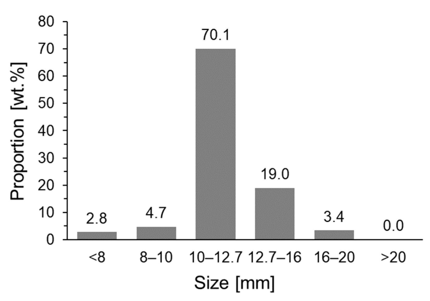
  • size distribution (which is important for the permeability of the ore burden layers in the furnace);
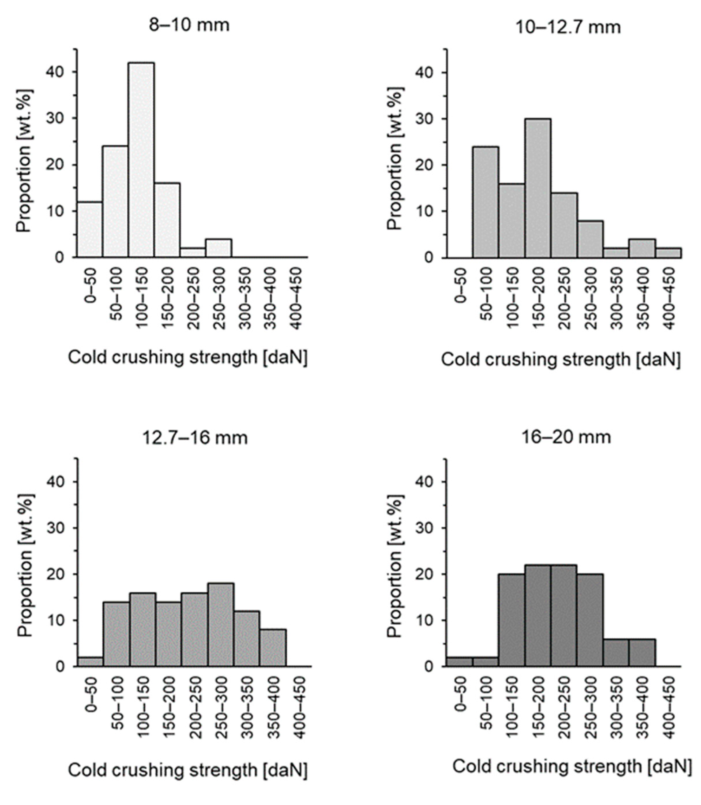
  • cold crushing strength (which is used to characterise the degradation of ore burden materials during transport and handling);
  • low-temperature reduction–disintegration (which characterises the effect of the reduction step of hematite to magnetite in the BF shaft);
  • reducibility (which characterises the ease of removing oxygen from iron ores);
  • swelling (which characterises the vulnerability to change in volume during reduction and is tested to ensure that the volume increase during reduction does not exceed a set maximum);
  • softening and melting properties (which are important for the formation of the cohesive and melting zone in the blast furnace).
Pellet size is an important factor because it has implications for blast furnace operation, affecting productivity, energy consumption and CO2 emissions. In this study, iron ore pellets of different sizes ranging from 8 to 20 mm were tested for chemical, physical and metallurgical properties. The microstructure and phase composition were studied using a field emission scanning electron microscope (FESEM) equipped with an energy-dispersive X-ray spectroscopy (EDS) detector. How the pellet size affects its metallurgical properties is discussed in this paper.

2. Materials and Methods

2.1. Iron Ore Pellets

Magnesia pellets from a commercial pellet producer were used in the investigations. A magnesium carbonate mineral named magnesite was used as MgO source in the pellets. Fundamentally, the pellets are acid type, with a basicity, B2, far below 0.5. A randomly selected batch of pellets was sieved into particle sizes of −8 mm, 8–10 mm, 10–12.7 mm, 12.7–16 mm, 16–20 mm and +20 mm, and the amount of each fraction was weighted. The size distribution for the pellet batch is shown in Figure 1. A portion of 70.1 wt.% of the total sample consisted of pellets with a particle size of 10–12.7 mm, which is also the target particle size in pelletising. No pellets sized +20 mm were included in the sample. The four size fractions between 8 mm and 20 mm were chosen for further investigations. Therefore, only −8 mm pellets (2.8 wt.% of the total sample) were discarded due to negligible commercial importance.
The chemical composition and basicity values of the four size fractions studied are shown in Table 1. Basicity is a universal ratio for the description of pellet chemistry. Different kinds of basicity values are widely used. B2 is the basicity based on two components (CaO and SiO2), and B4 is the basicity based on four components (CaO, SiO2, MgO and Al2O3,) as illustrated in Equations (1) and (2). Chemical composition was analysed by an accredited laboratory. CaO, SiO2, MgO, Al2O3 and S contents were measured with a Thermo Scientific™ ARL™ 9900 X-ray fluorescence (XRF) spectrometer, and total iron (Fetot) and the divalent iron (FeO) contents were measured by titration method with a Mettler Toledo DL50.
B 2 = CaO SiO 2
B 4 = CaO + MgO SiO 2 + Al 2 O 3
Figure 2 shows backscattered electron images captured by a Zeiss Ultra Plus FESEM from different-sized pellets. The basic structure in the pellets consists of iron oxides (hematite and/or magnetite, “O”), quartz grains (“Q”), magnesite grains (“M”) and pores (“P”). No major differences can be seen in the microstructure between different-sized pellets.
An example of FESEM-EDS elemental maps is shown in Figure 3 and is taken from a fired pellet sized 10–12.7 mm. Quartz grains are visible in Figure 3c in blue, a magnesite grain exists in Figure 3d in yellow, and pores can be seen in the elemental map for carbon in Figure 3g in red. The carbon in Figure 3g does not originate from the pellet but exists in the epoxy resin filling the pores in the sample matrix.

2.2. Reducibility Test

The reducibility of the pellets under unconstrained conditions was tested with a high-temperature furnace called a BFS (Blast Furnace Simulator), which has been previously used to investigate the reduction behaviour of ferrous burden materials under simulated BF conditions [8,9,10,11,12,13,14,15,16,17,18,19]. The BFS, a tube furnace with an inner diameter of 95 mm, is capable of producing complex time- and temperature-dependent atmosphere profiles according to predetermined programmes. In this study, the reduction experiments were carried out in CO-CO2-N2 gas, but hydrogen, water vapour, sulphur and potassium can also be used. The furnace tube and the sample basket are both made of heat-resistant steel, thus limiting the continuous operating temperature to 1100 °C. The operational description and layout of the BFS are presented in our earlier paper [8].
The reducibility of the pellets was dynamically tested in a CO-CO2-N2 gas from room temperature up to 1100 °C, simulating the average BF shaft gas. The total gas volume flow rate used here was 15 L/min at normal temperature and pressure (NTP) conditions. The test programme showing the gas composition and temperature as a function of the experimental time is presented in our earlier paper [10], referred to as the “no additives” test. It should be noted that the reducibility test carried out herein is not a standard test. The ISO 7215:2015 [20] reducibility test is carried out under isothermal conditions and in a static gas atmosphere, but the conditions in the blast furnace process actually vary significantly when the burden descends. The authors made the choice to use a customised reducibility test because the corresponding author of this paper concluded in his doctoral dissertation that material behaviour should preferably be studied non-isothermally under simulated process conditions instead of under simplified static conditions to obtain the most realistic results [11].
In the reducibility test, a loose-packed layer of pellets with a total weight of 120 ± 0.2 g was placed in a sample basket in the BFS high-temperature furnace. Prior to determination of the original weight of the pellets, the pellets were heat-treated at 110 °C overnight to remove any moisture. The experimental sample comprised 69, 36, 21 and 13 pellets sized 8–10 mm, 10–12.7 mm, 12.7–16 mm and 16–20 mm, respectively. Each reducibility test took 240 min (4 h) to reach 1100 °C, after which the reduction was continued isothermally for 40 min. After each reducibility test, the sample was cooled in a nitrogen flow until the sample reached a temperature of 200 °C to prevent sample oxidation. The cooling phase took 15–20 min.
The final reduction degree was calculated based on the weight change during the test and the total iron and divalent iron content from the chemical analysis. The weight change during the test was determined by measurements performed before and after the test with laboratory scales. Additionally, the online weight-measurement technique used in the reducibility tests provided an opportunity to draw the reduction degree curve as a function of experimental time. The final reduction degree (RDfinal) is represented by the ratio of the amount of oxygen removed from iron oxides to the amount bound to iron oxides and is calculated according to Equation (3) [20]:
RD final = m 1 m 2 m 1 ( 0.430 w 2 0.111 w 1 )   · 10 4
where m1 is the sample weight before reduction, m2 is the sample weight after reduction, w1 is the divalent iron content, and w2 is the total iron content. Values for w1 and w2 are taken from the chemical analysis of the fired pellets before reduction.

2.3. Reduction-Softening Test

The reduction-softening behaviour of the pellets was studied with an advanced reduction under load (ARUL) high-temperature furnace. The ARUL test is a dynamic reduction and softening test for pellets, sinters and lump ores that was developed at Rautaruukki (nowadays, SSAB Europe, Raahe Steel Works) for both research and quality-control purposes to study the high-temperature properties of ferrous burden materials [21]. Softening properties indicate how a BF burden loses its permeability when undergoing reduction. The ARUL test should not be confused with the ISO 7992:2015 [22] standardised RUL test. The ARUL reduction-softening test has been utilised in a several studies [10,11,15,21,23,24], and it is introduced in a review paper of high-temperature experimental techniques to investigate the cohesive zone of the blast furnace [25].
In the ARUL reduction-softening test, a loosely-packed layer of pellets with a height of 90 mm was put in a 70 mm diameter graphite cylinder with a perforated and removable bottom and lid. The compression was executed pneumatically so that the cylinder pushed the lid of the graphite crucible downwards while the bottom of the graphite crucible stood still. The initial sample weights were 697.4 g, 656.2 g, 654.6 g and 617.5 g for pellets with a particle size of 8–10 mm, 10–12.7 mm, 12.7–16 mm and 16–20 mm, respectively. The variations in the sample weights were caused by the differences in the voidage between the pellets in the sample basket.
The batch of iron ore pellets was simultaneously heated in a resistor furnace and continuously reduced in CO-CO2-N2 gas using a programme named MASSIM, which simulates the average gas in a BF. Figure 4 shows the operation line representing the average reducing conditions, with a black-coloured bold line in an Fe-O-C phase-stability diagram, which is usually referred to as a Baur–Glaessner diagram in the literature. The reducing gas was similar in the reducibility test, but the reducibility test was finished at 1100 °C, while the reduction-softening test continued to higher temperatures until the softening occurred. The experimental conditions are consistent with the general understanding of how CO-CO2 gas composition changes in the blast furnace shaft [4,26,27,28]. According to Geerdes et al. [4], a typical composition of BF shaft gas lies in the graph inside the grey-coloured area. The grey-coloured curve shows the gas composition in a European blast furnace, measured with descending probes [27]. More specific information about reduction-softening tests can be found in our earlier paper [23], including a schematic diagram of the ARUL reduction-softening test device and a graph showing the gas composition and the temperature as a function of the experimental time. The total gas volume flow rate used in the reduction-softening test was 20 L/min at NTP conditions.
In the reduction-softening test, a compression force of 200 kPa was started at 800 °C, and the compression lasted until the end of the test. The sample temperature inside the test burden, the pressure difference over the sample and the height of the test material were measured continuously during the test. The test was finished as the pressure difference over the sample increased to 7.0 kPa. At that stage, the structure of the sample had become so dense that the reducing gases had major difficulties penetrating through the material layer, simulating the cohesive zone in a BF. After each reduction-softening test, the sample was cooled in a nitrogen flow for several hours to prevent sample oxidation. After that, the sample was removed from the furnace.
To characterise the reduction-softening behaviour of the iron ore pellets, the following pressure-difference parameters were derived: The TDP20, TDP50 and TDP70 values state the temperature at pressure differences of 2.0 kPa, 5.0 kPa and 7.0 kPa, respectively. The TDP20 value was chosen to indicate the onset of softening, and the TDP70 value is the temperature when gases can no longer penetrate through the material layer, and the test is finished. RDfinal is the reduction degree at the end of the test and is calculated based on the weight change during the test and the total iron and divalent iron contents, according to Equation (3), presented earlier in this paper. The weight change during the test is determined by measurements performed with laboratory scales before and after the test. The compression of the material layer is calculated during the test from the measured displacement (in millimetres) in a vertical direction.
After the reduction-softening test, the sample cake was removed from the graphite crucible, weighted and photographed. Then, the sample was cut in two pieces, and the cross section was photographed. After that, a polished section was prepared from the top part of the cross-sectioned sample, as illustrated in our earlier paper [10]. The microstructures of the softened sample were first studied with an Olympus BX51 light optical microscope (LOM), after which the phase compositions were analysed with a Zeiss Ultra Plus field emission scanning electron microscope (FESEM) equipped with an Oxford Instruments energy-dispersive X-ray spectroscopy (EDS) detector. Before the EDS analyses, the polished sections were coated with carbon to ensure electrical conductivity. A total of 20 point analyses were carried out with an EDS detector for both the wüstite and the slag phases of each polished sample. The MgO content in the slag and the wüstite were of particular interest because MgO is known to have a positive effect on softening behaviour [29].

2.4. Cold Crushing Strength Test

The amount of pellet breakages during handling and charging of the blast furnace was evaluated according to the ISO 4700:2015 [30] standard using a crushing strength test apparatus, with the exception that only 50 pellets were compressed. In the test, a single pellet of a specific size range is compressed at a specific speed. The procedure is repeated on each pellet in the test portion. The test is complete when either the load falls to a value of 50% or more of the maximum load recorded or the platen gap has reduced to 50% of the initial mean test-piece diameter. In either case, the crushing strength is the maximum load attained in the test. The crushing strength is calculated as the arithmetic mean of all the measurements obtained.

2.5. Low-Temperature Reduction-Disintegration Test

The amount of size degradation of iron ores in the low-temperature reduction zone of the blast furnace was evaluated according to the ISO 13930:2015 [31] standard. The standard test gives a relative measure for evaluating the degree of degradation of iron ores when hematite is reduced to magnetite in the upper part of the blast furnace shaft. In the LTD test, the pellet sample was isothermally reduced at 500 °C in a rotating tube in CO-CO2-H2-N2 gas for 60 min. In this paper, the results of the LTD test are shown as the percentage of material greater than 6.3 mm (LTD+6.3). LTD−3.15 and LTD−0.5 values were not calculated.

3. Results and Discussion

3.1. Chemical Composition

Among those pellets studied, divalent iron content slightly increased in the pellets as the pellet size increased. The largest increase in FeO content was seen in those pellets over 12.7 mm in diameter. This result is in accordance with earlier studies by Dwarapudi et al. [7] and Umadevi et al. [3], as a drastic increase in FeO content beyond the 12.5 mm pellet size was seen in both of these studies. A high FeO content in the pellets is a result of insufficient oxidation during induration and is not desirable [7]. Another interesting observation is the relation between sulphur content and pellet size. The sulphur content increased in the pellets studied as the pellet size decreased. This might be because some sulphur originates from the fuel used in the induration furnace and transfers from the gas to the pellet surface. Sulphur is a harmful element in a blast furnace because of the possibility of forming an FeO–FeS liquid phase, which melts at relatively low temperatures. The phase diagram for an FeOn–Fe1−xS system in Slag Atlas [32] (p. 204) shows that the lowest liquidus temperature in the high-sulphur area of the system is as low as 908 °C.

3.2. Reduction Behaviour

The final reduction degrees for pellets of different sizes in the reducibility test under unconstrained conditions are presented in Table 2. The final reduction degrees were 61.9%, 60.2%, 55.7% and 51.4% for pellets sized 8–10 mm, 10–12.7 mm, 12.7–16 mm and 16–20 mm, respectively. The experiments showed that a small pellet size enhanced the reduction. This indicates topochemical reduction from the periphery towards the core of individual pellets. The reduction curves for the differently sized pellet samples are shown in Figure 5. Even though the small size of the pellets enhanced reduction, the graphs show only a minor difference in the reducibility between the pellets sized 8–10 mm and 10–12.7 mm until the 1100 °C isotherm. The reduction degree of 11.0% is marked in the figure as a dashed horizontal line, indicating the end of hematite-to-magnetite reduction stage. Additionally, the reduction degrees of 29.6% and 33.2% marked in the figure indicate the end of the magnetite-to-wüstite reduction stage, depending on whether the non-stoichiometric characteristic of wüstite is considered or not. The shapes of the reduction curves with areas of rapid and slow progresses of weight changes are related to the stepwise reduction starting from hematite to magnetite, continuing to wüstite and finally ending with metallic iron.
Another interesting point is that pellet cracking was intensified as the pellet size increased. Figure 6 shows the pellet sample images before and after the reducibility tests. Small pellets did not crack at all during reduction, and cracking was most intensified in the largest size fraction. This is most obviously due to the dualistic structure of a magnetite core and a hematite shell in the large pellets. In our earlier study [8], the boundary between the original magnetite nucleus and the hematite shell was shown to act as the source of cracks. The formation of cracks opens space for gases to more easily penetrate inward to the pellet core. Even though cracks were formed in large pellets, the large pellets reduced more slowly than smaller pellets because the formation of cracks was surface-oriented. No abnormal swelling was detected in any of the size fractions of the pellets when visually comparing the pellet images before and after the reducibility tests.

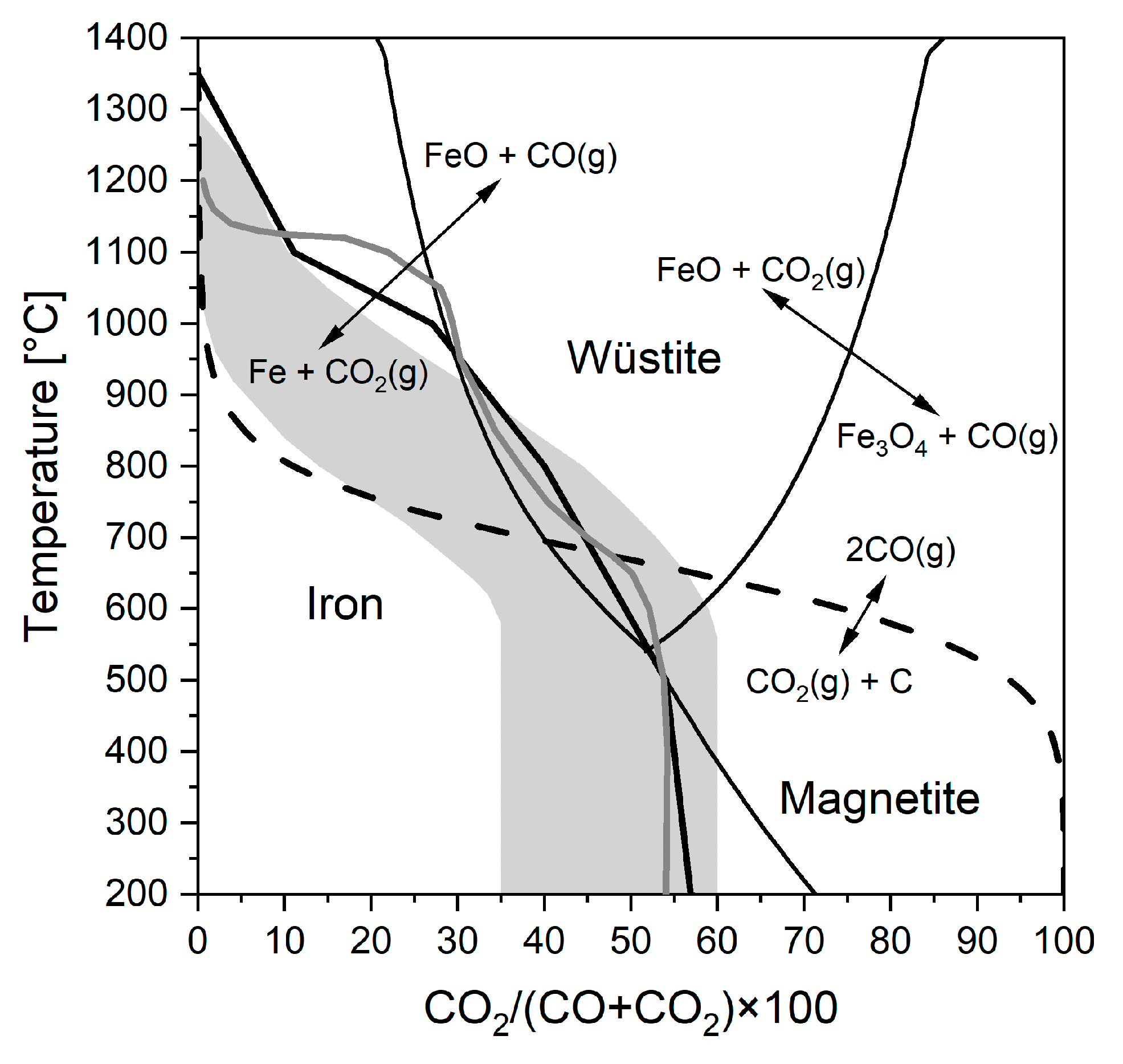
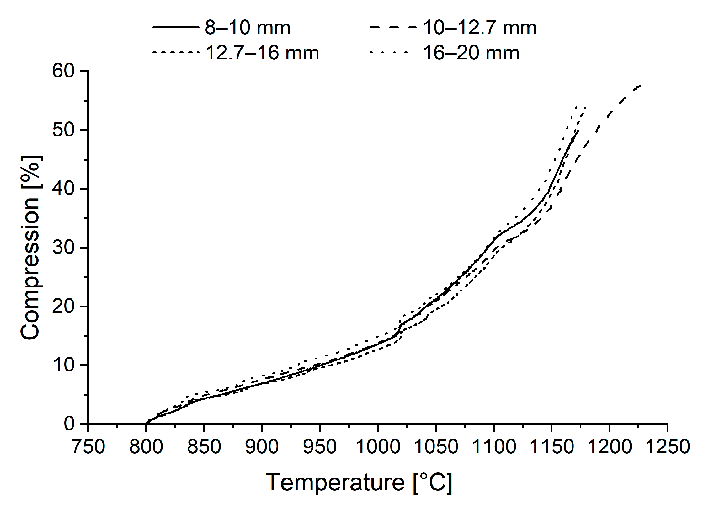
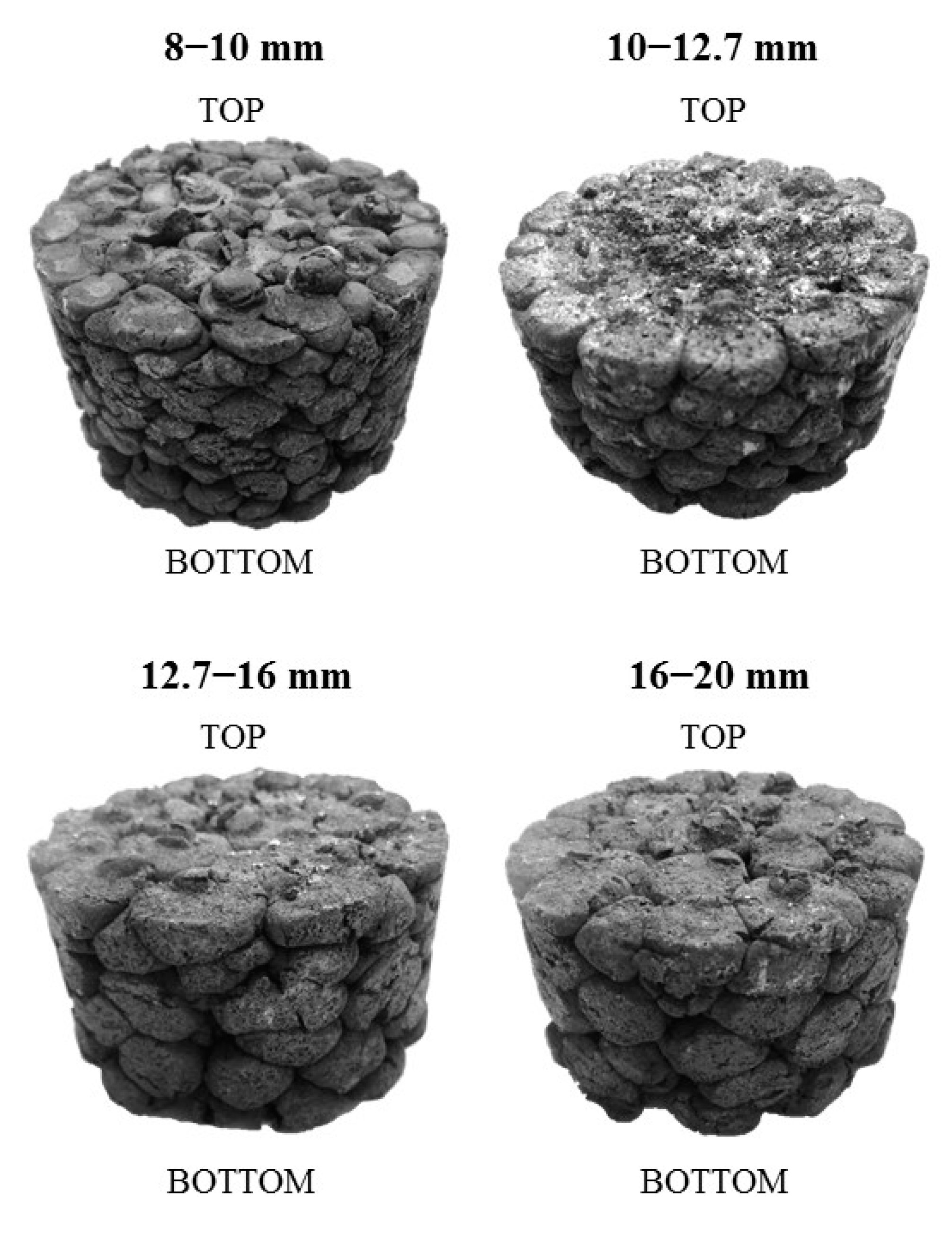
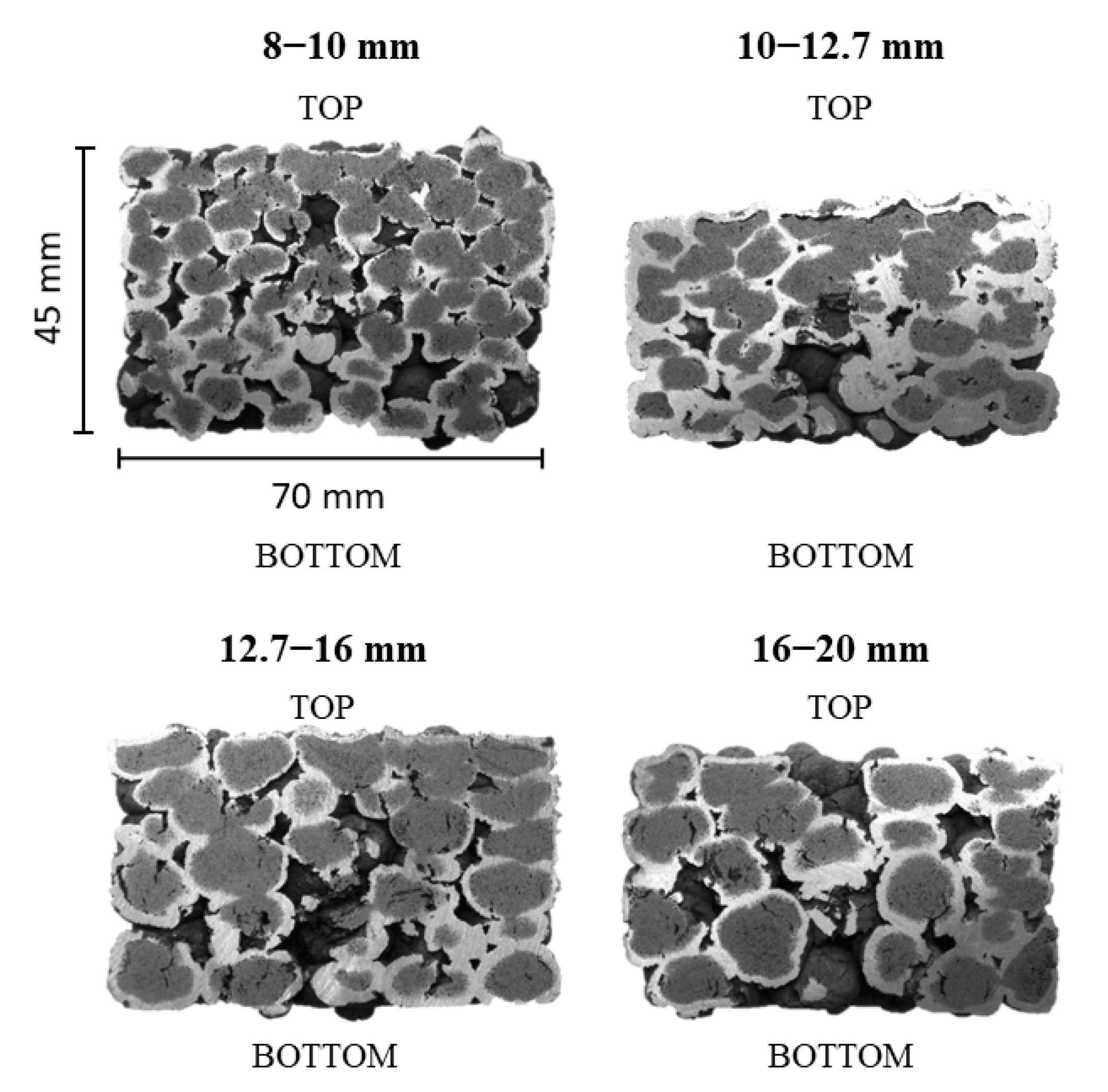
3.3. Reduction-Softening Behaviour

The pressure-difference parameters, together with the compressibility and the reducibility values, are shown in Table 3 for the different-sized pellets in the reduction-softening tests. The final temperatures and the final reduction degrees were nearly the same with size fractions other than 10–12.7 mm, which resisted a temperature of 51 °C higher before losing gas permeability and reduced to a 9.8% unit higher final reduction degree compared to the other size fractions, on average. The final temperatures of the tests were 1173 °C, 1227 °C, 1179 °C and 1175 °C for the 8–10 mm, 10–12.7 mm, 12.7–16 mm and 16–20 mm sized pellets, respectively. The final reduction degrees were 51.6%, 61.8%, 52.1% and 52.4% for the 8–10 mm, 10–12.7 mm, 12.7–16 mm and 16–20 mm sized pellets, respectively.
The pressure difference over the material layer stayed relatively constant until it rapidly increased in the melt-exudation stage. This can be seen in Figure 7, which shows the pressure difference in the reduction-softening tests as a function of the measured sample temperature. The marked increase in the pressure difference over the sample bed occurred in the following order: 8–10 mm, 16–20 mm, 12.7–16 mm and 10–12.7 mm pellets, respectively. The pressure difference over the sample increased notably more slowly with the 10–12.7 mm pellets compared to the other pellet size fractions studied.
In the reduction-softening test, the compression was started at 800 °C, as stated earlier. There are no significant differences in the compression curves in Figure 8 between different-sized pellets; however, the pellets sized 10–12.7 mm resisted compression better at high temperatures when softening occurred. Compression occurs at a steady speed up to approximately 1020 °C, and after that, compression continues with a higher speed. At this transition point, wüstite starts to reduce to metallic iron, which can be deduced from the reduction curves in Figure 5.
After the reduction-softening experiments, the samples were photographed (see Figure 9). The orientation in the image is similar to the orientation in the test device; thus, the reducing gases have gone through the burden from bottom to top. The top part in the 10–12.7 mm pellets shows the most softened structure because of the highest final temperature attained in the test.
Cross sections of the ARUL samples are shown in Figure 10. The orientation in the image is similar to the orientation in the test device. Light grey depicts metallic iron, and dark grey depicts wüstite or macropores. Wüstite seems to be the predominant phase of iron after the reduction-softening test, and partly reduced (wüstite) areas are located practically at the core of the pellets, indicating topochemical reduction from the periphery towards the core of individual pellets. Pellet cross sections also showed that the highest proportion of metallic iron was formed in the 10–12.7 mm pellets.
However, some differences in the reduction and compression behaviours of the different-sized pellets can be seen in the cross-sectioned samples in Figure 10. The pellets sized 16–20 mm show topochemical reduction from the pellet periphery towards the core in both the bottom and the top part of the softened sample because of high voidage between pellets side by side. It seems that the extent of reduction is nearly the same in the bottom and the top part of the pellet sample. Instead, the bottom part of the pellets sized 8–10 mm is visually reduced to a greater extent compared to the top part of the sample. This is due to lower voidage between the pellets side by side, decreasing the burden permeability. Pellet samples sized 10–12.7 mm compressed the most due to the highest final temperature in the reduction-softening test. This also means that individual pellets are flattened the most, and there is little or no voidage visible in the softened pellet samples after the reduction-softening tests. The voidage between the pellets side by side in the sample cylinder is linked to the initial weight of the pellet sample in the reduction-softening test. The initial weight in the reduction-softening test increased as the pellet size decreased because of a denser packing and a minor wall effect. The phenomenon of the wall or floor of a container affecting the packing structure of spherical particles is called the wall effect [33]. Because of this, the packing structure and local voidage are different near the walls compared to the centre of the container. Despite the more unfavourable ratio between sample weight and total gas flow rate, pellets sized 10–12.7 mm reduced to a significantly greater reduction degree compared to the larger pellets.
The ARUL samples were studied with FESEM-EDS to obtain information about microstructure and phase composition after softening. The investigation area was limited to the poorly reduced area at the top of the pellet cake, in which a lot of wüstite remained. This choice was made because a previous study by Kemppainen et al. [13] indicated that the softening of iron ore pellets is caused by the softening of the pellet core, where wüstite is the dominant phase of iron. Figure 11 shows an FESEM-EDS mapping of elements of the softened pellets. The example analysis was carried out for pellets sized 10–12.7 mm. White-coloured grains in the FESEM image are metallic iron droplets; light grey, round-shaped grains are wüstite; and a dark grey colour between the wüstite grains presents the slag phase. Microscopic study verified that MgO exists mainly in the silicate phase (slag) between wüstite grains and is also partly dissolved in the wüstite.
Average compositions for the wüstite and the slag calculated from the point analyses are shown in Table 4 and Table 5, respectively. The phase compositions were normalised to 100%. Other components include CaO, Al2O3 and SiO2 in the wüstite, and CaO and Al2O3 in the slag, and their total amount was less than 1.0 wt.% in each point analysis. More MgO is dissolved to the wüstite in the 10–12.7 mm pellets (1.0 wt.%) compared to the other pellet sizes (0.0–0.2 wt.%), increasing the melting point of the (magnesio)wüstite [34]. Simultaneously, pellets sized 10–12.7 mm show a remarkably higher MgO content in the slag (9.5 wt.%) compared to the other pellet sizes (6.0–6.5 wt.%), increasing the liquidus temperature of the slag [34]. These microscopic observations are in accordance with the experimental results, as pellets sized 10–12.7 mm showed the highest final temperature in the reduction-softening test (1227 °C vs. 1173–1179 °C) and the highest final reduction degree (61.8% vs. 51.6–52.4%). The higher the reduction degree, the higher MgO contents are assumed in the slag and wüstite because MgO does not dissolve in metallic iron. Additionally, the higher the final temperature, the more time the magnesite grains (which are the source for MgO in the pellets) have to react with the slag and wüstite, resulting in a higher MgO content in the slag and wüstite phases. A high softening temperature and a high reduction degree at the cohesive zone are favourable for BF operation, indicating less direct reduction occurring in the blast furnace hearth and a lower need for reducing agents in the process.

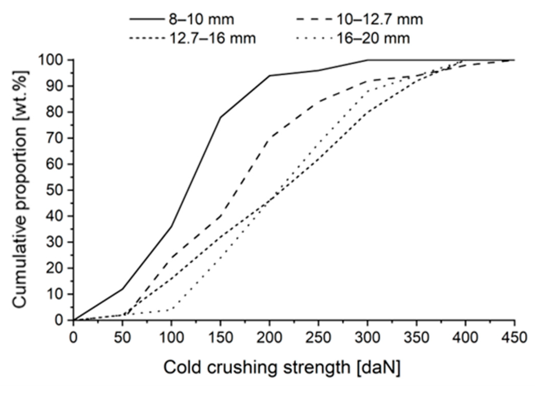
3.4. Cold Crushing Strength

In a blast furnace operation, CCS must be at a sufficient level to withstand the pressure of the burden in the BF shaft. An acceptable reported level for the CCS value of pellets used in the blast furnace varies in literature from 150 daN [4] to 200–230 daN [5,35,36]. Furthermore, Geerdes et al. [4] point out that a slightly lower average compressive strength has no drawback for the blast furnace process as long as it is not caused by an increased percentage of very weak pellets (<60 daN).
Numerical values of the CCS tests are depicted in Table 6. The average cold crushing strength increased from 118 daN to 211 daN as the particle size increased from 8–10 mm to 12.7–16 mm and stayed at the highest level with the 16–20 mm pellets. This result is not in accordance with the studies by Umadevi et al. [3] and Dwarapudi et al. [7], both of which reported similar CCS values for 8–10 mm pellets compared to 10–12.5 mm pellets and a decrease in CCS in pellets larger than 12.5 mm. The reason for the lower CCS value with large pellets compared to smaller ones is explained in both studies by the dualistic structure, including hematite in the shell and magnetite in the core, which causes severe lattice and bond strains, as well as concentric cracks. This dualistic structure was visible in 12.5–16 mm and +16 mm pellets, where the divalent iron content in the pellets was 3.0 wt.% at the maximum. Those pellets studied here have a lower divalent iron content of 0.6 wt.% at the maximum, indicating a lower proportion of magnetite in the core; hence, the dualistic magnetite/hematite structure was not that strong.
Cumulative CCS distribution curves and CCS histograms for different-sized pellets are presented in Figure 12 and Figure 13, respectively. As pellet size increased from 8–10 mm to 16–20 mm, the proportion of weak pellets (<150 daN) and very weak pellets (<60 daN) decreased by 69% and 88%, respectively. A proportion of 78 wt.% of pellets sized 8–10 mm had a CCS value lower than 150 daN, and similarly, they showed an increased percentage (16 wt.%) of very weak pellets (<60 daN). Almost all pellets sized −10 mm were classified as weak (<150 daN). From the batch of pellets studied, pellets sized −10 mm (a total of 7.5 wt.% of the pellet sample) were found capable of causing operational difficulties due to their low cold crushing strength.

3.5. Low-Temperature Reduction-Disintegration

LTD values for different-sized pellets are shown in Table 7. Low-temperature reduction-disintegration decreased from 80.7% to 47.9% as pellet size increased from 8–10 mm to 16–20 mm, indicating better resistance against reduction-disintegration for smaller pellets in the upper BF shaft area.
In the LTD test, more fines were generated as the particle size increased. One can see in Table 1 that the divalent iron content is slightly higher in the large pellets compared to the small pellets, and this indicates a larger magnetite nucleus in the pellet core. Small pellets have either a small magnetite nucleus or no magnetite nucleus at all. In our earlier study [8], the boundary between the magnetite nucleus and the hematite shell was shown to be weak and vulnerable to cracking. The dualistic pellet structure might explain why more fines were formed in large pellets compared to smaller ones in the LTD test.
Instead of the LTD test, Dwarapudi et al. [7] and Umadevi et al. [3] carried out the reduction-disintegration (RDI) test on pellets, which is a metallurgical test similar to the LTD test, but tumbling is carried out after reduction in the RDI test, when in turn the sample is reduced in a rotating tube in the LTD test. Umadevi et al. [3] noticed an increase in RDI−6.3 and RDI−0.5 values with an increase in pellet size. Superior RDI was found with pellets sized 8–10 mm and 10–12.5 mm. This was explained by better distribution of the slag phase in small pellets. Similarly, Dwarapudi et al. [7] reported superior RDI for pellets under 12.5 mm in size, and this could be attributed to a large amount and better distribution of silicate melt.

3.6. Implications for Material Testing and Industrial Relevance

Operational conditions in induration furnaces greatly affect the metallurgical properties (including reducibility, softening, CCS and LTD) of the produced pellets. The operation of induration furnaces must be optimised to produce good-quality pellets with a certain size distribution, and it is hardly impossible to simultaneously produce both small and large pellets of superior quality. Therefore, it is favourable that the target pellet size distribution is narrow enough. This also means that if the target pellet size distribution is altered, firing conditions (i.e., temperature) must be also adjusted.
There are a variety of standard tests for characterising the metallurgical properties of iron ore materials for use in blast furnaces. Standards give an accurate and simplified procedure concerning how the material indices are determined. According to the international ISO standards, which are commonly used to measure the metallurgical properties of iron ore pellets, the size range of the pellets should be certain. The ISO standards prefer the size range of 10–12.5 mm for pellets when determining reducibility [20,37], reduction under load [22], crushing strength [30] and RDI [38,39] but provide two optional size ranges (12.5–16.0 mm or 10.0–12.5 mm) when testing LTD [31].
Based on the implications drawn from this study, the particle size of pellets markedly affects their behaviour in metallurgical tests. Hence, these tests should be done with a certain size range to be able to obtain comparable results. This also means that if, for some reason, a metallurgical property is determined for two or more different pellet qualities with different-sized pellets, the experimental results are not comparable to each other.
Among the samples studied, pellets sized 10–12.7 mm showed the highest metallurgical properties, on average, when compared to other sizes of pellets between 8 and 20 mm. Therefore, the proportion of 10–12.7 mm should be maximised in blast furnace operations to achieve superior reducibility and softening behaviour. This main conclusion is in accordance with two earlier studies [3,7], which concluded that pellets in the range of 8–12.5 mm showed good chemical, physical and metallurgical properties [3] and that the proportion of pellets over 12.5 mm should be minimised [7].

4. Conclusions

In this study, the effect of pellet size on the metallurgical properties of magnesia iron ore pellets was investigated. Reduction and softening behaviour, cold crushing strength and low-temperature reduction-disintegration were determined separately for pellets sized 8–10 mm, 10–12.7 mm, 12.7–16 mm, and 16–20 mm. The results obtained in this study are summarised as follows:
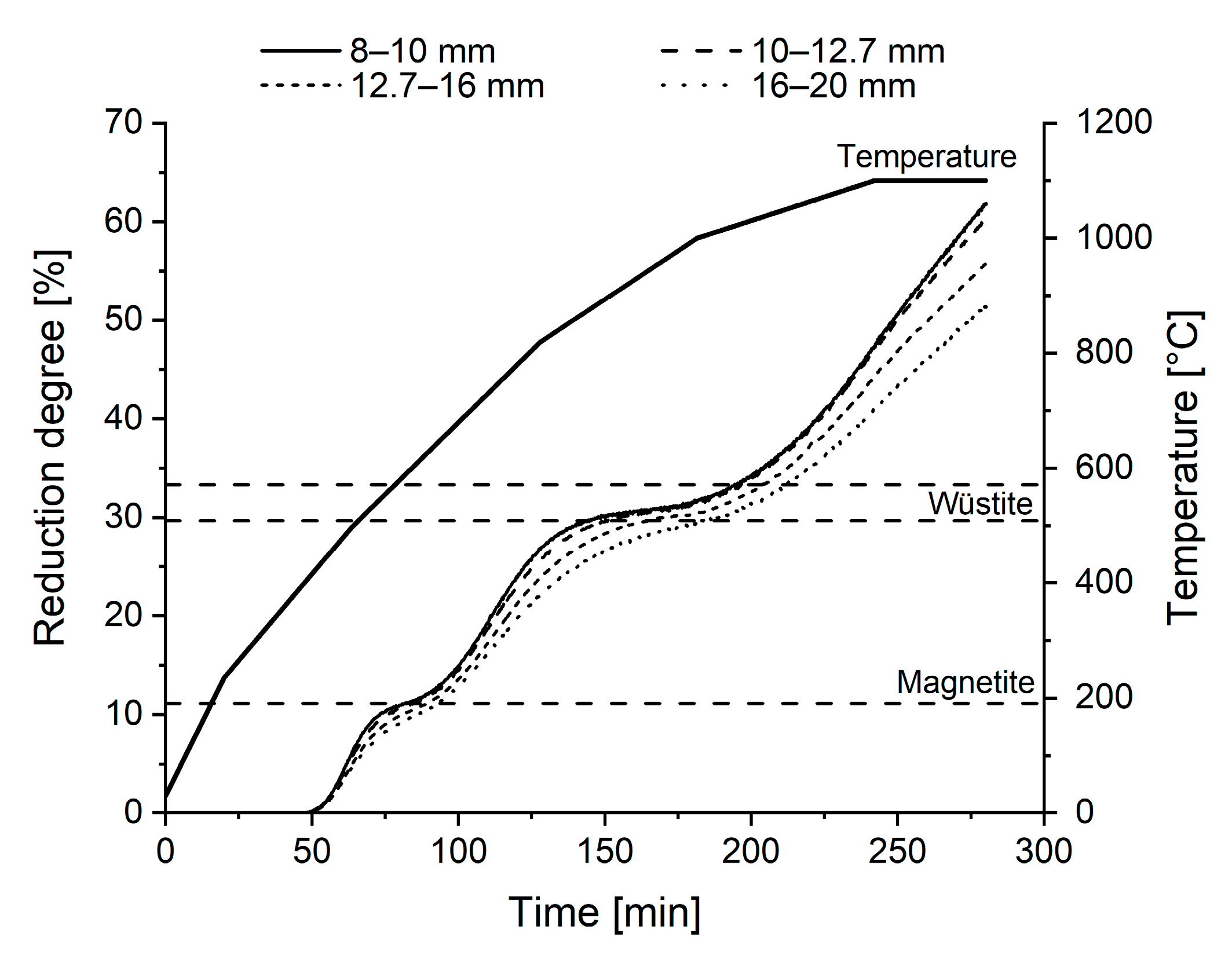
  • Reducibility under unconstrained conditions decreased as pellet size increased. This is due to the topochemical reduction from the pellet periphery towards the core. However, the difference between 8–10 mm and 10–12.7 mm pellets was not significant.
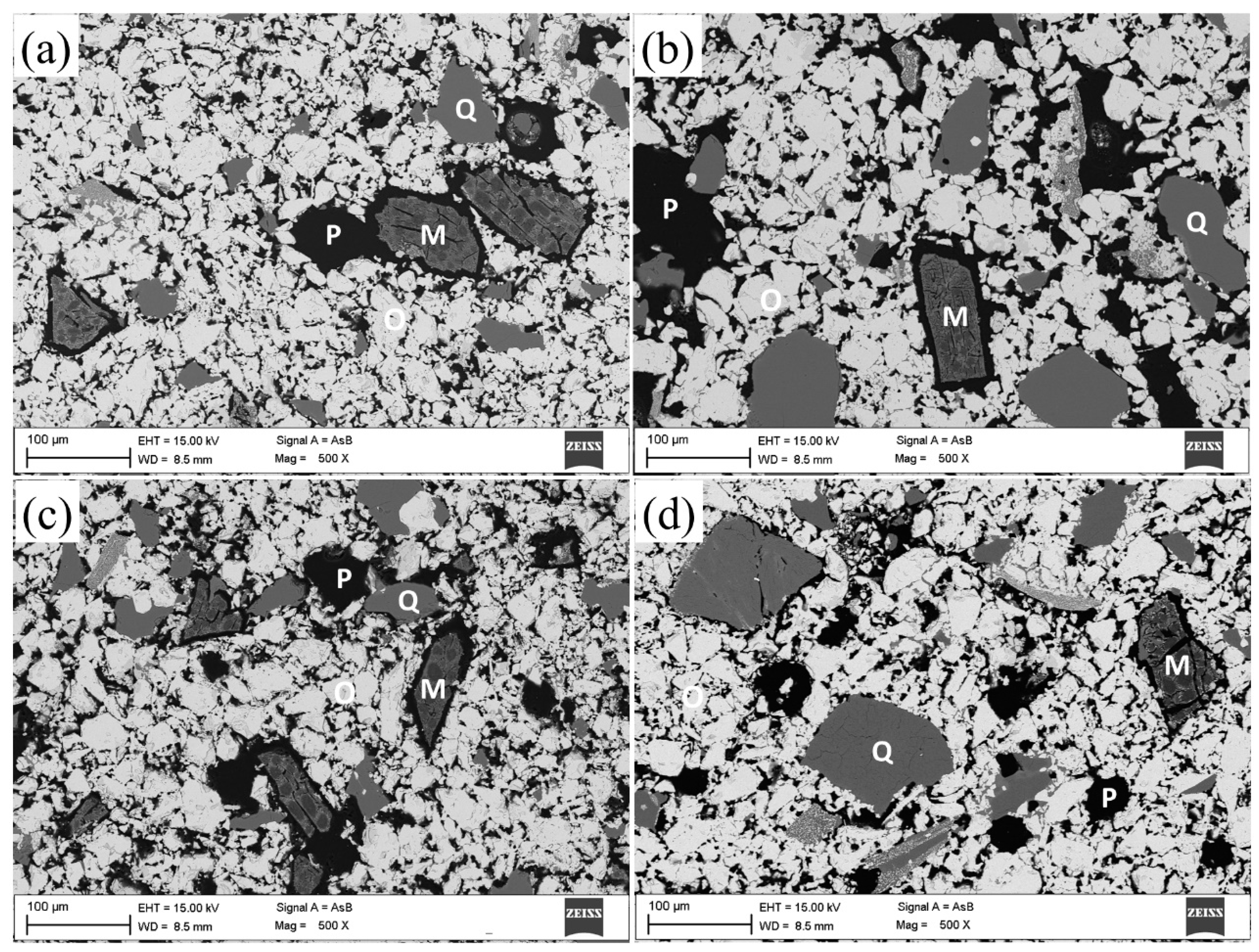
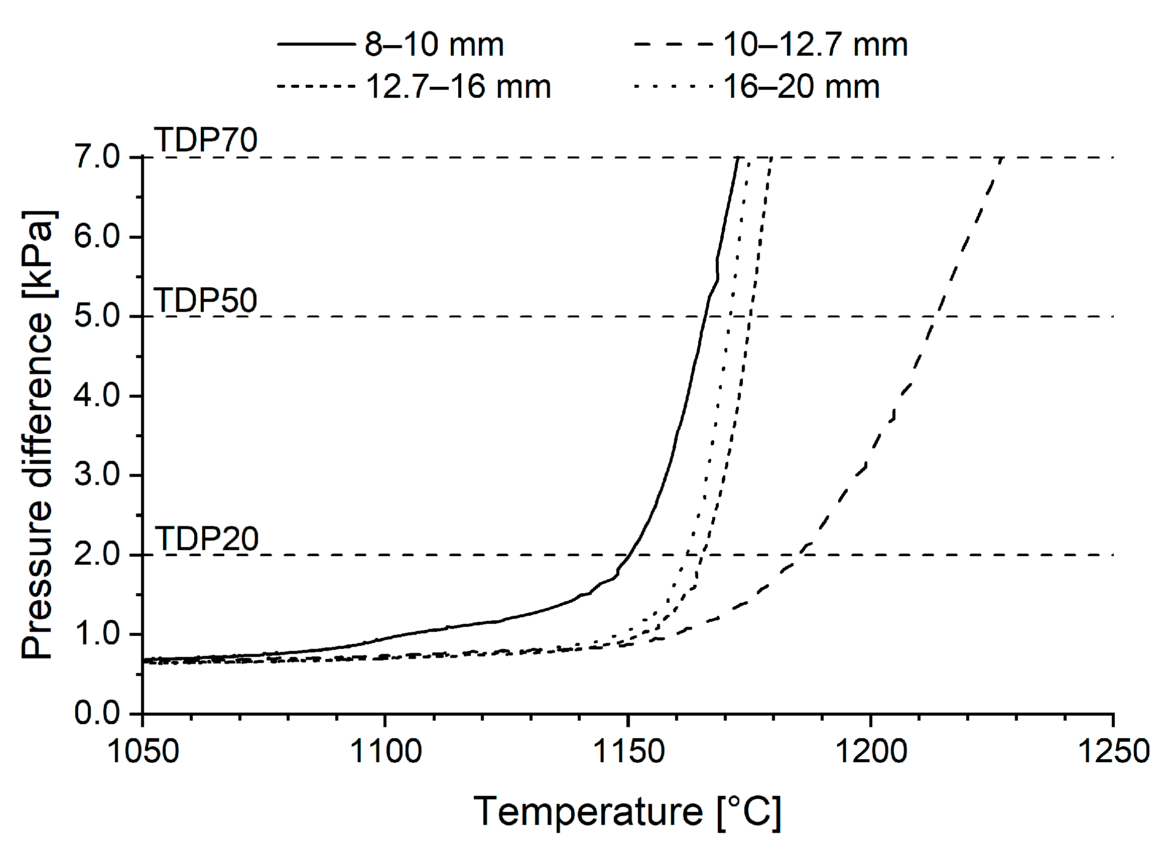
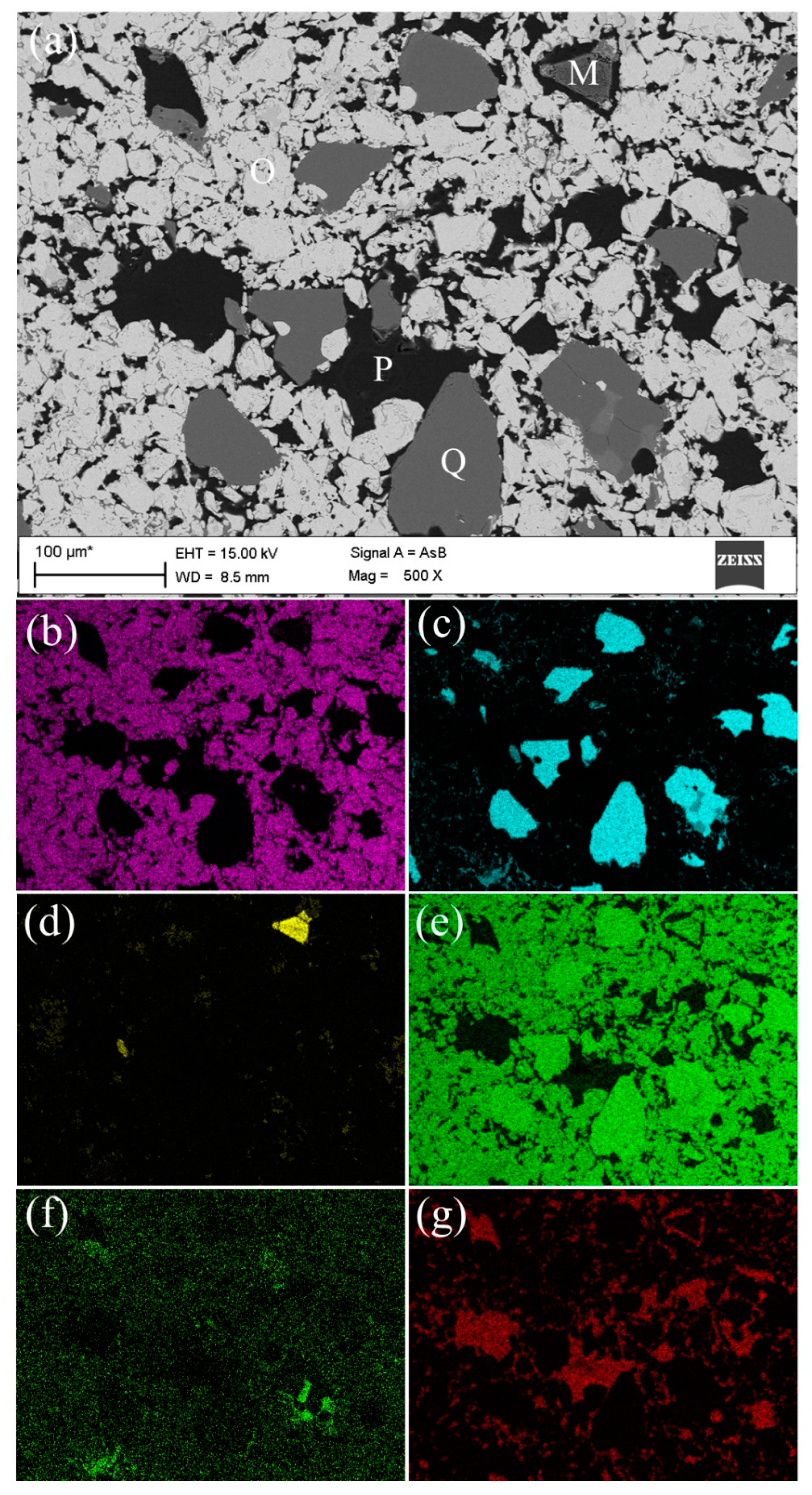
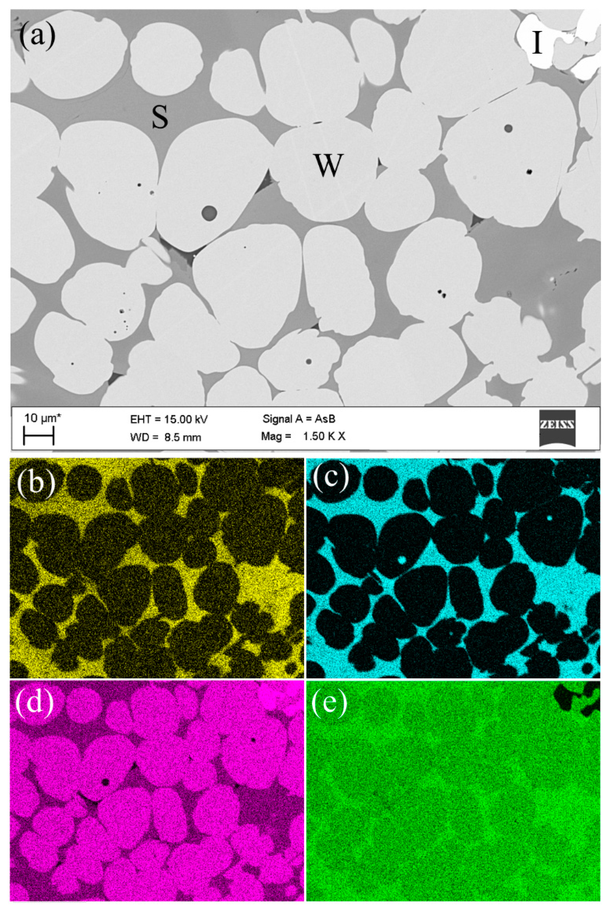
  • Pellets sized 10–12.7 mm reached the highest final temperature and the highest reduction degree in the ARUL reduction-softening test. The highest proportions of MgO in the silicate slag and in the wüstite were verified with FESEM-EDS in the 10–12.7 mm size, increasing the softening temperature of the pellets. A higher reduction degree in the cohesive zone indicates less direct reduction occurring in the blast furnace hearth and a lower need for reducing agents in the process.
  • Cold crushing strength increased, on average, as pellet size increased. Simultaneously, the proportion of weak pellets (<150 daN) and very weak pellets (<60 daN) decreased, which is favourable in a blast furnace operation. Almost all pellets sized −10 mm were classified as weak.
  • Small pellets showed better resistance against reduction-disintegration compared to large pellets in the LTD test. LTD values were very low for +12.7 mm pellets. High resistance against reduction-disintegration in the upper BF shaft is favourable in a blast furnace operation.
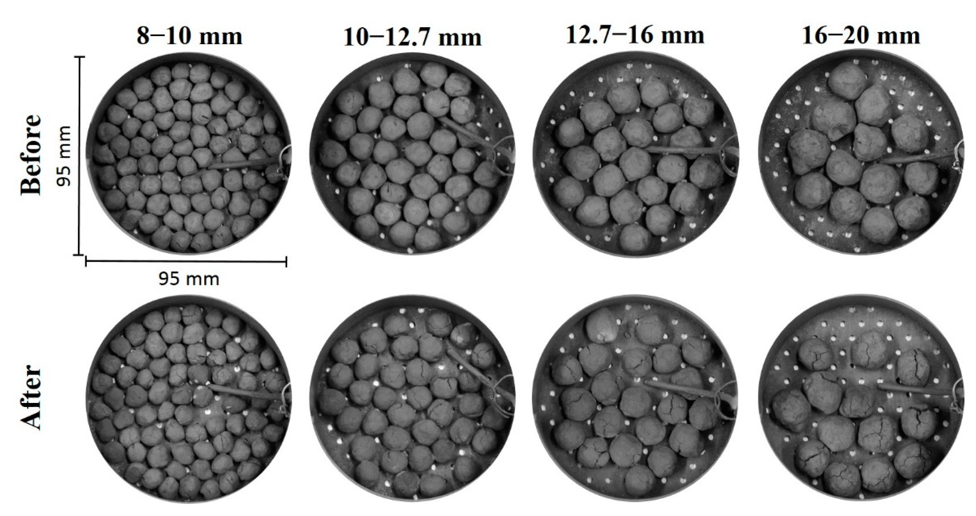
  • No abnormal swelling was detected in any of the size fractions of pellets during non-isothermal reduction up to 1100 °C.
  • Among the samples studied, pellets sized 10–12.7 mm had the highest metallurgical properties, on average. Therefore, a pellet batch should consist of pellets in that size range as much as possible for a smooth and efficient blast furnace operation.
  • To conclude, pellet size influences metallurgical properties of iron ore pellets, and is therefore of the utmost importance to standardise particle size when comparing metallurgical properties among different pellet qualities.

Author Contributions

Conceptualization, M.I.; methodology, M.I.; formal analysis, M.I.; investigation, M.I.; resources, T.F. and T.P.; writing—original draft preparation, M.I.; writing—review and editing, M.I., M.K., O.M., T.F. and T.P.; visualization, M.I.; supervision, T.F. All authors have read and agreed to the published version of the manuscript.

Funding

This research was funded by Business Finland as a part of the Towards Fossil-free Steel (FFS) research programme, grant number 45774/31/2020.

Institutional Review Board Statement

Not applicable.

Informed Consent Statement

Not applicable.

Data Availability Statement

Not applicable.

Acknowledgments

The Centre for Material Analysis (CMA) at the University of Oulu is acknowledged for providing mineralogical characterization services. Tommi Kokkonen, a special laboratory technician at the University of Oulu, is acknowledged for his technical support. Antti Kemppainen, formerly a process development engineer at SSAB Europe Oy, Raahe, Finland, is acknowledged for fruitful discussions about the topic of this paper.

Conflicts of Interest

Mikko Iljana, the corresponding author, acts as a post-doctoral researcher at the University of Oulu and declare no personal conflict of interest. Timo Paananen, a co-author, acts as a process development manager and Olli Mattila, a co-author, as a process development engineer, both at SSAB Europe Oy, Raahe, Finland. Mikhail Kondrakov, a co-author, acts as a chief executive at Karelsky Okatysh, Severstal, Kostomuksha, Russia. Timo Fabritius, a co-author, is a member in the steering group of the FFS research programme and has participated on the decision making to publish the results. The funder (Business Finland) had no role in the design of the study; in the collection, analyses, or interpretation of data, or in the writing of the manuscript. The funder as a member of the steering group has only participated on the decision making to publish the results.

References

  1. Mousa, E.A. Modern Blast Furnace Ironmaking Technology: Potentials to Meet the Demand of High Hot Metal Production and Lower Energy Consumption. Metall. Mater. Eng. 2019, 25, 69–104. [Google Scholar] [CrossRef] [Green Version]
  2. Zhu, D.; Pan, J.; Lu, L.; Holmes, R.J. Iron Ore Pelletization. In Iron Ore: Mineralogy, Processing and Environmental Sustainability; Elsevier: Amsterdam, The Netherlands, 2015; pp. 435–473. [Google Scholar] [CrossRef]
  3. Umadevi, T.; Kumar, P.; Lobo, N.F.; Mahapatra, P.C.; Prabhu, M.; Ranjan, M. Effect of Iron Ore Pellet Size on Its Properties and Microstructure. Steel Res. Int. 2009, 80, 709–716. [Google Scholar] [CrossRef]
  4. Geerdes, M.; Chaigneau, R.; Kurunov, I.; Lingiardi, O.; Ricketts, J. Modern Blast Furnace Ironmaking, 3rd ed.; IOS Press BV: Amsterdam, The Netherlands, 2015; ISBN 978-1-61499-498-5. [Google Scholar]
  5. Dwarapudi, S.; Ghosh, T.K.; Tathavadkar, V.; Denys, M.B.; Bhattacharjee, D.; Venugopal, R. Effect of MgO in the Form of Magnesite on the Quality and Microstructure of Hematite Pellets. Int. J. Miner. Process. 2012, 112–113, 55–62. [Google Scholar] [CrossRef]
  6. Niiniskorpi, V. Development of Phases and Structures during Pelletizing of Kiruna Magnetite Ore. Ph.D. Thesis, Åbo Akademi University, Åbo Akademi, Finland, 2004. [Google Scholar]
  7. Dwarapudi, S.; Umadevi, T.; Rao, S.M.; Ranjan, M. Influence of Pellet Size on Quality and Microstructure of Iron Ore Pellets. ISIJ Int. 2008, 48, 768–776. [Google Scholar] [CrossRef] [Green Version]
  8. Iljana, M.; Mattila, O.; Alatarvas, T.; Visuri, V.-V.; Kurikkala, J.; Paananen, T.; Fabritius, T. Dynamic and Isothermal Reduction Swelling Behaviour of Olivine and Acid Iron Ore Pellets under Simulated Blast Furnace Shaft Conditions. ISIJ Int. 2012, 52, 1257–1265. [Google Scholar] [CrossRef] [Green Version]
  9. Iljana, M.; Mattila, O.; Alatarvas, T.; Kurikkala, J.; Paananen, T.; Fabritius, T. Effect of Circulating Elements on the Dynamic Reduction Swelling Behaviour of Olivine and Acid Iron Ore Pellets under Simulated Blast Furnace Shaft Conditions. ISIJ Int. 2013, 53, 419–426. [Google Scholar] [CrossRef] [Green Version]
  10. Iljana, M.; Kemppainen, A.; Paananen, T.; Mattila, O.; Pisilä, E.; Kondrakov, M.; Fabritius, T. Effect of Adding Limestone on the Metallurgical Properties of Iron Ore Pellets. Int. J. Miner. Process. 2015, 141, 34–43. [Google Scholar] [CrossRef]
  11. Iljana, M. Iron Ore Pellet Properties under Simulated Blast Furnace Conditions. Investigation on Reducibility, Swelling and Softening. Ph.D. Thesis, University of Oulu, Oulu, Finland, 2017. [Google Scholar]
  12. Kemppainen, A.; Iljana, M.; Heikkinen, E.-P.; Paananen, T.; Mattila, O.; Fabritius, T. Reduction Behavior of Cold-Bonded Briquettes under Simulated Blast Furnace Conditions. ISIJ Int. 2014, 54, 1539–1545. [Google Scholar] [CrossRef] [Green Version]
  13. Kemppainen, A.; Ohno, K.-I.; Iljana, M.; Mattila, O.; Paananen, T.; Heikkinen, E.-P.; Maeda, T.; Kunitomo, K.; Fabritius, T. Softening Behaviors of Acid and Olivine Fluxed Iron Ore Pellets in the Cohesive Zone of a Blast Furnace. ISIJ Int. 2015, 55, 2039–2046. [Google Scholar] [CrossRef] [Green Version]
  14. Kemppainen, A. Limiting Phenomena Related to the Use of Iron Ore Pellets in a Blast Furnace. Ph.D. Thesis, University of Oulu, Oulu, Finland, 2015. [Google Scholar]
  15. Kemppainen, A.; Iljana, M.; Heikkinen, E.-P.; Paananen, T.; Mattila, O.; Fabritius, T. Recent Development in the Evaluation of the High-Temperature Properties of Iron Ore Pellets. In Proceedings of the SCANMET V, 5th International Conference on Process Development in Iron and Steelmaking, Luleå, Sweden, 12–15 June 2016; Swerea MEFOS: Luleå, Sweden , 2016. ISBN 978-91-639-1233-7. [Google Scholar]
  16. Kemppainen, A.; Mousa, E.; Wang, C.; Suopajärvi, H.; Iljana, M.; Heikkinen, E.-P.; Fabritius, T. Introduction of Biomass Lignin to Blast Furnace Process as Cement Substitute in Cold-Bonded Briquettes. In Proceedings of the 1st International Conference on Energy and Material Efficiency and CO2 Reduction in the Steel Industry (EMECR), Kobe, Japan, 11–13 October 2017; The Iron and Steel Institute of Japan: Tokyo, Japan, 2017; pp. 386–389. [Google Scholar]
  17. Heikkilä, A.; Iljana, M.; Bartusch, H.; Fabritius, T. Reduction of Iron Ore Pellets, Sinter and Lump Ore under Simulated Blast Furnace Conditions. In Proceedings of the METEC & 4th European Steel Technology and Application Days (ESTAD), Düsseldorf, Germany, 24–28 June 2019; Steel Institute VDEh: Düsseldorf, Germany, 2019. [Google Scholar]
  18. Heikkilä, A.; Iljana, M.; Bartusch, H.; Fabritius, T. Reduction of Iron Ore Pellets, Sinter, and Lump Ore under Simulated Blast Furnace Conditions. Steel Res. Int. 2020, 91, 2000047. [Google Scholar] [CrossRef] [Green Version]
  19. Abdelrahim, A.; Iljana, M.; Omran, M.; Vuolio, T.; Bartusch, H.; Fabritius, T. Influence of H2–H2O Content on the Reduction of Acid Iron Ore Pellets in a CO–CO2–N2 Reducing Atmosphere. ISIJ Int. 2020, 60, 2206–2217. [Google Scholar] [CrossRef]
  20. ISO 7215:2015; Iron Ores for Blast Furnace Feedstocks—Determination of the Reducibility by the Final Degree of Reduction Index. ISO: Geneva, Switzerland, 2015; pp. 1–11.
  21. Hooey, P.L. Reduction and High Temperature Behaviour of Iron Ore Sinter Made from Magnetite Fines. Ph.D. Thesis, University of Oulu, Oulu, Finland, 1999. [Google Scholar]
  22. ISO 7992:2015; Iron Ores for Blast Furnace Feedstocks—Determination of Reduction under Load. ISO: Geneva, Switzerland, 2015; pp. 1–12.
  23. Iljana, M.; Kemppainen, A.; Paananen, T.; Mattila, O.; Heikkinen, E.-P.; Fabritius, T. Evaluating the Reduction-Softening Behaviour of Blast Furnace Burden with an Advanced Test. ISIJ Int. 2016, 56, 1705–1714. [Google Scholar] [CrossRef] [Green Version]
  24. Iljana, M.; Kemppainen, A.; Heikkinen, E.-P.; Fabritius, T.; Paananen, T.; Mattila, O. A New Sophisticated Method for Evaluating the Reduction-Softening Properties of Iron Burden Materials. In Proceedings of the METEC & 2nd European Steel Technology and Application Days (ESTAD), Düsseldorf, Germany, 16–20 June 2015; Steel Institute VDEh: Düsseldorf, Germany, 2015. [Google Scholar]
  25. Liu, X.; Honeyands, T.; Evans, G.; Zulli, P.; O’Dea, D. A Review of High-Temperature Experimental Techniques Used to Investigate the Cohesive Zone of the Ironmaking Blast Furnace. Ironmak. Steelmak. 2019, 46, 953–967. [Google Scholar] [CrossRef]
  26. Peters, K.-H.; Beppler, E.; Gerstenberg, B.; Janhsen, U. Burden Properties and Their Influence on Process in the Blast Furnace. In Proceedings of the 53rd Ironmaking Conference, Chicago, IL, USA, 20–23 March 1994; Iron & Steel Society: Warrendale, PA, USA, 1994; pp. 257–267. [Google Scholar]
  27. Chaigneau, R.; Bakker, T.; Steeghs, A.; Bergstrand, R. Quality Assessment of Ferrous Burdens: Utopian Dream? In Proceedings of the 60th Ironmaking Conference, Baltimore, MD, USA, 25–28 March 2001; Iron & Steel Society: Warrendale, PA, USA, 2001; pp. 689–703. [Google Scholar]
  28. Bailly, J.L.; Picard, M.; Sert, D.; Succurro, A.; Rougé, M.; Reboul, J.L. A New Measuring Device for the Simultaneous Evaluation of Heat Pattern and Gas Utilisation Pattern in the Shaft of a Blast Furnace. In Measuring Techniques in Blast Furnace Ironmaking and their Benefits for Industrial Practice; ECSC Workshop: Düsseldorf, Germany, 1998; pp. 139–152. ISBN 92-828-4281-9. [Google Scholar]
  29. Iljana, M.; Heikkinen, E.-P.; Fabritius, T. Estimation of Iron Ore Pellet Softening in a Blast Furnace with Computational Thermodynamics. Metals 2021, 11, 1515. [Google Scholar] [CrossRef]
  30. ISO 4700:2015; Iron Ore Pellets for Blast Furnace and Direct Reduction Feedstocks—Determination of the Crushing Strength. ISO: Geneva, Switzerland, 2015; pp. 1–5.
  31. ISO 13930:2015; Iron Ores for Blast Furnace Feedstocks—Determination of Low-Temperature Reduction-Disintegration Indices by Dynamic Method. ISO: Geneva, Switzerland, 2015; pp. 1–9.
  32. Verein Deutscher Eisenhüttenleute (VDEh) (Ed.) Slag Atlas, 2nd ed.; Verlag Stahleisen GmbH: Düsseldorf, Germany, 1995; ISBN 3-514-00457-9. [Google Scholar]
  33. Suzuki, M.; Shinmura, T.; Iimura, K.; Hirota, M. Study of the Wall Effect on Particle Packing Structure Using X-Ray Micro Computed Tomography. Adv. Powder Technol. 2008, 19, 183–195. [Google Scholar] [CrossRef]
  34. Borinder, T.; Torssell, K. High Temperature Behaviour of Blast Furnace Pellets. In Proceedings of the 45th Ironmaking Conference, Washington, DC, USA, 6–9 April 1986; Iron & Steel Society: Warrendale, PA, USA, 1986; pp. 13–18. [Google Scholar]
  35. Dwarapudi, S.; Ghosh, T.K.; Shankar, A.; Tathavadkar, V.; Bhattacharjee, D.; Venugopal, R. Effect of Pyroxenite Flux on the Quality and Microstructure of Hematite Pellets. Int. J. Miner. Process. 2010, 96, 45–53. [Google Scholar] [CrossRef]
  36. Dwarapudi, S.; Ghosh, T.K.; Shankar, A.; Tathavadkar, V.; Bhattacharjee, D.; Venugopal, R. Effect of Pellet Basicity and MgO Content on the Quality and Microstructure of Hematite Pellets. Int. J. Miner. Process. 2011, 99, 43–53. [Google Scholar] [CrossRef]
  37. ISO 4695:2015; Iron Ores for Blast Furnace Feedstocks—Determination of the Reducibility by the Rate of Reduction Index. ISO: Geneva, Switzerland, 2015; pp. 1–12.
  38. ISO 4696-1:2015; Iron Ores for Blast Furnace Feedstocks—Determination of Low-Temperature Reduction-Disintegration Indices by Static Method—Part 1: Reduction with CO, CO2, H2 and N2. ISO: Geneva, Switzerland, 2015; pp. 1–11.
  39. ISO 4696-2:2015; Iron Ores for Blast Furnace Feedstocks—Determination of Low-Temperature Reduction-Disintegration Indices by Static Method—Part 2: Reduction with CO and N2. ISO: Geneva, Switzerland, 2015; pp. 1–10.
Figure 1. Size distribution of the fired pellets on a weight basis.
Metals 12 00302 g001
Figure 2. Backscattered electron images by FESEM from the core of pellets sized (a) 8–10 mm, (b) 10–12.7 mm, (c) 12.7–16 mm and (d) 16–20 mm. “O” stands for iron oxides (hematite and/or magnetite), “M” for magnesite, “Q” for quartz and “P” for pore.
Metals 12 00302 g002
Figure 3. FESEM-EDS mapping of elements of a fired pellet sized 10–12.7 mm. Figure (a) is the original backscattered electron image, and the EDS mapping of elements is presented in: (b) Fe, (c) Si, (d) Mg, (e) O, (f) K and (g) C (pores). “O” stands for iron oxides (hematite and/or magnetite), “M” for magnesite, “Q” for quartz and “P” for pore.
Metals 12 00302 g003
Figure 4. Reducing conditions in the reduction-softening test marked with a black-coloured bold line in an Fe-O-C phase-stability diagram. The grey area shows the typical blast furnace conditions, and the grey curve depicts the conditions in a European blast furnace, measured with descending probes.
Metals 12 00302 g004
Figure 5. Reduction degree as a function of experimental time for different-sized pellets.
Metals 12 00302 g005
Figure 6. Digital camera images of the samples before (upper) and after (lower) the reducibility tests.
Metals 12 00302 g006
Figure 7. Evolutions of pressure difference in the reduction-softening tests.
Metals 12 00302 g007
Figure 8. Evolutions of compression in the reduction-softening tests.
Metals 12 00302 g008
Figure 9. Digital images of the samples after the reduction-softening tests.
Metals 12 00302 g009
Figure 10. Digital images of cross sections of the samples after the reduction-softening tests. The final temperatures of the tests were 1173 °C, 1227 °C, 1179 °C and 1175 °C for pellets sized 8–10 mm, 10–12.7 mm, 12.7–16 mm and 16–20 mm, respectively.
Metals 12 00302 g010
Figure 11. FESEM-EDS mapping of elements of softened pellets sized 10–12.7 mm. Figure (a) is the original backscattered electron image, and the EDS mapping of elements is presented in: (b) Mg, (c) Si, (d) Fe and (e) O. “I” stands for metallic iron, “W” for wüstite and “S” for slag.
Metals 12 00302 g011
Figure 12. Cumulative CCS distribution curves for different-sized pellets.
Metals 12 00302 g012
Figure 13. CCS histograms of the different-sized pellets.
Metals 12 00302 g013
Table 1. Chemical composition (in wt.%) and basicity for different-sized pellets.
Component/Basicity8–10 mm10–12.7 mm12.7–16 mm16–20 mm
Fetot64.2564.0564.1864.20
FeO<0.10.20.60.6
SiO25.315.485.645.33
MgO1.401.471.401.53
CaO0.240.200.150.18
Al2O30.320.320.310.29
S0.0040.0020.0010.001
B20.0450.0360.0270.034
B40.290.290.260.30
Table 2. Numerical values of the reducibility tests.
Index8–10 mm10–12.7 mm12.7–16 mm16–20 mm
Number of pellets69362113
Initial weight [g]120.20120.20120.08120.23
RDfinal [%]61.960.255.751.4
Table 3. Numerical values of the reduction-softening tests.
Index8–10 mm10–12.7 mm12.7–16 mm16–20 mm
TDP20 [°C]1151118611651163
TDP50 [°C]1166121411761172
TDP70 [°C]1173122711791175
TDP70—TDP20 [°C]22411412
Compressionfinal [%]49.958.053.855.2
RDfinal [%]51.661.852.152.4
Table 4. Average compositions (in wt.%) for wüstite after the reduction-softening tests for different-sized pellets.
Size FractionMgOFeOOthers
8–10 mm0.0100.00.0
10–12.7 mm1.098.60.4
12.7–16 mm0.299.70.1
16–20 mm0.199.70.2
Table 5. Average compositions (in wt.%) for slag after the reduction-softening tests for different-sized pellets.
Size FractionMgOFeOSiO2Others
8–10 mm6.062.830.30.9
10–12.7 mm9.559.231.00.3
12.7–16 mm6.562.930.20.4
16–20 mm6.563.030.30.2
Table 6. Numerical values of the CCS tests.
Index8–10 mm10–12.7 mm12.7–16 mm16–20 mm
Average [daN]118171211211
Standard deviation [daN]53.785.892.176.4
Proportion of <150 daN [wt.%]78403224
Proportion of <60 daN [wt.%]16442
Table 7. LTD values for different-sized pellets.
Index8–10 mm10–12.7 mm12.7–16 mm16–20 mm
Proportion of >6.3 mm [wt.%]80.767.950.647.9
Publisher’s Note: MDPI stays neutral with regard to jurisdictional claims in published maps and institutional affiliations.

