Article

Al-Mn Intermetallics in High Pressure Die Cast AZ91 and Direct Chill Cast AZ80

1
Department of Materials, Imperial College London, London SW7 2AZ, UK
2
School of Materials Science and Engineering, Central South University, Changsha 410083, China
3
Brunel Centre for Advanced Solidification Technology (BCAST), Brunel University London, Uxbridge UB8 3PH, UK
4
China Science Lab, General Motors Global Research & Development, 56 Jinwan Road, Shanghai 201206, China
*
Authors to whom correspondence should be addressed.
Metals 2022, 12(2), 266; https://doi.org/10.3390/met12020266
Submission received: 14 December 2021 / Revised: 23 January 2022 / Accepted: 27 January 2022 / Published: 31 January 2022

Abstract

:
Manganese-bearing intermetallic compounds (IMCs) are important for ensuring adequate corrosion performance of magnesium-aluminium alloys and can be deleterious to mechanical performance if they are large and/or form clusters. Here, we explore the formation of Al-Mn IMCs in Mg-9Al-0.7Zn-0.2Mn produced by two industrial casting processes, high-pressure die casting (HPDC) and direct chill (DC) casting. As Al8Mn5 starts forming above the α-Mg liquidus temperature in this alloy, we consider its formation during melt handling as well as during casting and heat treatment. In HPDC, we focus on sludge formation in the holding pot, partial solidification of IMCs in the shot chamber, and Al-Mn IMC solidification in the die cavity. In DC casting, we focus on interactions between Al-Mn IMCs and oxide films in the launder system, Al-Mn IMC solidification in the billet, and the partial transformation of Al8Mn5 into Al11Mn4 during solution heat treatment. The results show that minimising pre-solidification in the shot sleeve of HPDC and controlling pouring and filtration in DC casting are important for ensuring small Al-Mn intermetallic particles in these casting processes.

1. Introduction

AZ series alloys are the most widely used Mg alloys in the automotive industry for lightweight requirements, while providing adequate strength at an acceptable cost [1,2,3,4]. The Al and Zn contents normally range from ~3 to 9 wt.% Al and ~0 to 2 wt.% Zn for different levels of strength and processability. For high strength AZ alloys, the mostly commonly used composition is approximately Mg-9Al-0.7Zn-0.2Mn (wt.%), with low levels of transition metal impurities. The standard name of this alloy depends on the processing route: AZ91D when used for high pressure die casting (HPDC) [5], AZ91E when used for sand casting and investment casting [6,7], and AZ80A when used for forgings [8]. As shown in Figure 1, the limits of the AZ91 and AZ80 composition ranges overlap over much of their range.
Mg-9Al-0.7Zn-0.2Mn produced by these different processing routes are used in different applications. HPDC AZ91D is used for thin-walled one-piece automotive parts such as the transmission case, 4-wheel drive transfer case, valve cover, oil pan, steering box, and clutch pedal [2]. AZ80A produced by direct chill (DC) casting and forging is used for wrought wheels in motor racing and high performance cars [9], as well as in structural helicopter components [10].
AZ alloys also contain a small but important manganese addition. If manganese is not added, the impurity iron reacts with aluminium solute in the liquid to form Al-Fe intermetallic compounds (IMCs), which act as damaging micro-cathodes in the anodic α-Mg, resulting in unacceptable corrosion rates [12,13,14,15,16]. The addition of ~0.15–0.50 wt.% Mn ties up low levels of impurity Fe in Al-Mn IMCs with Fe partially occupying Mn lattice sites. These Al-Mn IMCs are closely correlated to the micro-galvanic corrosion in the α-Mg matrix [13,17,18,19], and usually act as less-damaging micro-cathodes in α-Mg [12,13].
Al-Mn IMCs formed during casting normally have a minor effect on the mechanical properties in the as-cast condition (e.g., [20]) as their volume fraction is small (~0.25 wt.%), and they are evenly distribution in the microstructure. However, past work [21] has shown that Al8Mn5 particles can cluster on entrained oxide and form large defects that can significantly reduce the yield strength and embrittle the alloy.
In recent years, there have been extensive studies [22,23,24,25,26,27,28,29,30,31,32,33,34] that have advanced the understanding of the fundamentals of Al-Mn IMC behaviour in magnesium alloys based on controlled laboratory experiments. However, it is unclear how these findings relate to Al-Mn IMC formation in industrial casting processes. The aim of this study is to link from experiments on the fundamentals of Al-Mn IMCs formation during solidification and solution heat treatment to Al-Mn IMCs in castings produced by high-pressure die casting (HPDC) and direct chill (DC) casting. The paper is split into three parts. We first overview key results from laboratory studies on Al-Mn IMC formation during solidification and solution heat treatment of Mg-9Al-0.7Zn-0.2Mn. We then explore how this compares with Al-Mn IMCs in HPDC AZ91D in the as-cast condition, as HPDC parts are often not heat-treated. Finally, we explore DC cast AZ80A in the solutionised condition as this is the usual starting material for forging.
The mechanical behaviour of the HPDC and DC cast samples was not studied here. Past work has shown that, in the as-cast condition, HPDC parts usually have higher yield stress and lower elongation than equivalent DC cast parts [2] owing to HPDCs’ finer microstructural length scale, but higher amount of casting defects. The yield strength of DC cast ingot can be substantially improved by forging with or without a subsequent precipitation heat treatment [35]. The role of Al8Mn5 particles on deformation and fracture in AZ91/AZ80 is discussed in [31,33].

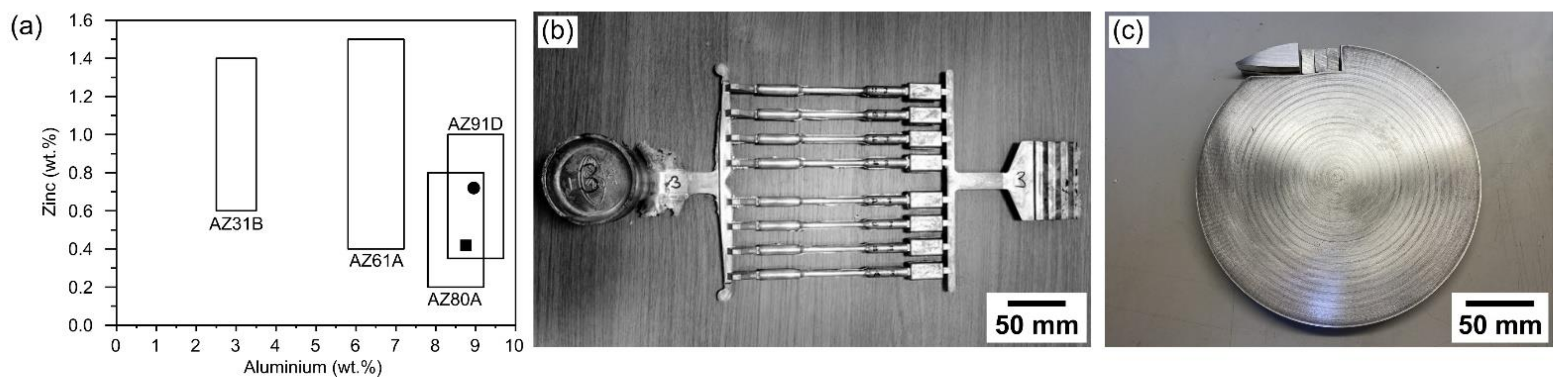
2. Materials and Methods

Al-Mn IMCs were studied in three types of casting: (i) samples from an AZ91 laboratory study, (ii) an HPDC AZ91D casting (Figure 1b) and sludge from an HPDC holding pot, and (iii) a DC-cast billet of AZ80A (Figure 1c).
The laboratory solidification study started with a batch of high purity AZ91 ingot with the composition in Table 1. AZ91 cylinders of ~2 g were cut from the ingot. Flat-bottomed cylindrical Al2O3 crucibles with dimensions of inner diameter 9 mm and height 30 mm were adopted to avoid the effect of Fe from conventional steel crucibles. The AZ91 cylinders in the Al2O3 crucibles were melted and held at 700 °C for 120 min, within sealed quartz tubes backfilled with Ar. After the desired holding time, the samples were solidified in one of two ways. In method 1, the hot quartz tube was placed in the vertical cylindrical hole of a steel mould at room temperature. The cooling rate was measured as ~1 K/s. In method 2, the furnace was turned off and the lid was removed, leading to a slow cooling rate of ~0.1 K/s. In method 2, the cooling rate was abruptly increased at 430 °C by removing the quartz tube to the hole in a steel mould at room temperature to minimise any solid-state transformations after solidification.
To study the solid-state transformation of Al-Mn IMCs during solution heat treatment, specimens were cut from similar locations of the AZ91 ingot into ~20 mm × 20 mm × 20 mm cubes. These specimens were held in a forced-air convection oven at 410 ± 4 °C for different times (0, 0.5, 1, 2, 3, 5, 6, 21, and 90 days) and then cooled in water. For heat treatments longer than 6 days, samples were sealed in quartz tubes backfilled with Ar. Samples for other shorter heat treatments were coated by boron nitride and directly placed in the oven.
To study HPDC samples of AZ91D, ingots were used from the same batch of AZ91 as in the laboratory solidification study with the composition in Table 1. The alloy was heated in a mild steel crucible to 675 °C (~75 °C superheat). HPDC was performed using a Frech DAK 450–54 cold chamber HPDC machine with a die preheated to 150 °C and further heated by at least six pre-shots. The shot chamber fill fraction was ~0.5 and the set parameters were slow shot phase 0.3 m s−1, fast shot phase 4 m s−1, and intensification pressure 36 MPa. The die produced the tensile bars casting in Figure 1b. Additionally, a sample of sludge was shovelled from the bottom of an industrial HPDC holding pot of AZ91 to produce a sample to study the settled IMCs.
To study a DC cast billet of AZ80A, a 20 mm thick slice from a 210 mm diameter DC cast forging billet was provided by Magnesium Elektron. This billet has been solutionised after casting and had the composition in Table 1. Note that both alloys studied here have compositions that simultaneously conform with the requirements of AZ91D and AZ80A, as shown in Figure 1a.
The microstructure of Al-Mn IMC particles was examined by analytical scanning electron microscopy (SEM). Cross sections were prepared via grinding with ethanol with #2000 and #4000 grit SiC paper for ~1 and 5 min, respectively, followed by polishing with 20% OPS in ethanol for 12 min, and cleaned in ultrasonic bath in ethanol. SEM investigation was performed using a Zeiss Sigma-300. To reveal the 3D morphology of IMC particles, the samples were etched in 10% nitric acid in ethanol for 5–10 min to selectively dissolve the α-Mg. HPDC samples were etched in a solution of 200 mL of ethylene glycol, 68 mL of distilled water, 4 mL nitric acid, and 80 mL acetic acid. Secondary electron (SE) and backscattered electron (BSE) images were taken with an accelerating voltage of 10 kV and a working distance of 10 mm. Energy-dispersive X-ray spectroscopy (EDS) was performed using an accelerating voltage of 10 kV, a 60 μm aperture, and a working distance of 5 mm with an OXFORD X-Max detector. Electron backscattered diffraction (EBSD) was carried out using 20 kV accelerating voltage and 15 mm working distance, with a 120 μm aperture, the sample tilted at 70°, and a Bruker e-FlashHR EBSD detector. For indexing of EBSD patterns, the phases that were considered in the Bruker Quantax Esprit 2.1 and Bruker DynamicS software are listed in Table 2 along with their crystallographic details and references to the original crystallographic studies.
To further understand Al-Mn IMCs in HPDC samples, focused ion beam (FIB) tomography was conducted. A Zeiss AURIGA FEG-SEM equipped with a gallium FIB was used at 30 kV and 52-degree tilt angle. Serial-sectioning FIB milling was conducted with a slice distance of 90 nm and current of 200 pA. Secondary electron images were then aligned, cropped, and processed by an anisotropic diffusion filter in ImageJ (US NIH, USA). 3D reconstruction and crystallographic analysis was performed using Avizo 9.2 (Visualization Science Group, France) and MATLAB 9.2TM.
The results presented here come from analysis of more than 100 particles from 50 samples in laboratory cast AZ91 samples, various locations in two HPDC bars, and various locations from two DC cast billets.

3. Results and Discussion

3.1. Laboratory Study on Al-Mn IMCs in Solidification and Solution Heat Treatment

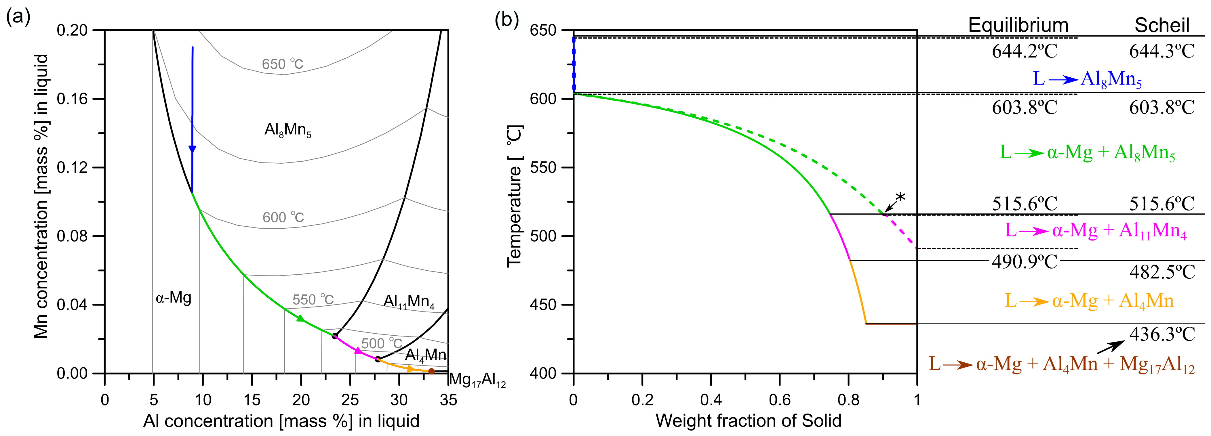
3.1.1. Thermodynamic Calculations

Figure 2 overviews the development of Al-Mn IMCs during the solidification of Al-8.95Al-0.19Mn (wt.%) for equilibrium solidification and for the Scheil model, calculated in Thermo-Calc software with the TCMG4.0 database. Zn was omitted from the calculation to better visualise the liquidus projection and because the solubility of Zn in the Al-Mn IMCs is very low. Al-Mn IMCs form throughout the solidification sequence. The first IMC, Al8Mn5, is stable above the α-Mg liquidus temperature as a primary solidification phase. Below the α-Mg liquidus, Al8Mn5 and then Al11Mn4 are calculated to form with α-Mg for equilibrium solidification. With the Scheil model, an additional IMC, Al4Mn, is calculated to form with α-Mg before solidification ends with a eutectic reaction involving Mg17Al12. Although they form in all stages of the solidification sequence, the Al-Mn IMCs make up only ~0.25 mass% of the alloy after Scheil solidification, of which ~95% is Al8Mn5.

3.1.2. Growth of Al8Mn5 during Solidification

Past work has confirmed that the majority Al-Mn phase after casting of AZ91 is Al8Mn5 [23,24,26] and that it usually has the morphology of equiaxed particles or, more rarely, rods [23,24,31]. Zeng et al. identified that the equiaxed particles are cyclic twins [24]. Figure 3 shows a typical Al8Mn5 equiaxed particle in Mg-9Al-0.7Zn-0.2Mn. From the BSE image and the EBSD phase map in Figure 3a, it can be seen that Al8Mn5 grew as an equiaxed multifaceted polyhedral particle. According to the IPF-X orientation map, there were four orientations (colours) present in this single-phase particle with three clear linear interfaces.
The experimental Kikuchi patterns of the four orientations are attached beneath in Figure 3b with the wire frame unit cells of rhombohedral Al8Mn5 plotted from the EBSD-measured Euler angels. These Kikuchi patterns look similar in most of the main bands, but differences can be observed in some weaker bands, confirming that there were four distinct orientations in Al8Mn5 and the EBSD technique can readily distinguish them.
Similar to our previous work [24], those rhombohedral Al8Mn5 in Figure 3 were cyclic twinned related by ~90° rotation around three common 11 2 ¯ 0 H E X axes with 2 2 ¯ 01 H E X twin planes. This cyclic twin can be understood better when considering Al8Mn5 in the body centred rhombohedral (BCR) setting of Al8Mn5 with lattice parameters a = b = c = 9.029 Å, α = β = γ = 89.1° [41], which is pseudo-cubic with <1° rhombohedral distortion. In the BCR setting, the cyclic twin planes are 100 B C R and the four orientations rotate ~90° around the 100 B C R axes. This cyclic twin orientation relationship (OR) can be identified in the pole figures in Figure 3c, where all four orientations overlap at each spot in the 100 B C R in the pole figure. The plane normal of the 100 B C R is also perpendicular to the linear interface in the IPF-X orientation map, indicating that the twin planes are 100 B C R . The cyclic twin OR can be visualized in the wire frames attached to the pole figures. Further information on cyclic twinning in Al8Mn5 is given in [24].

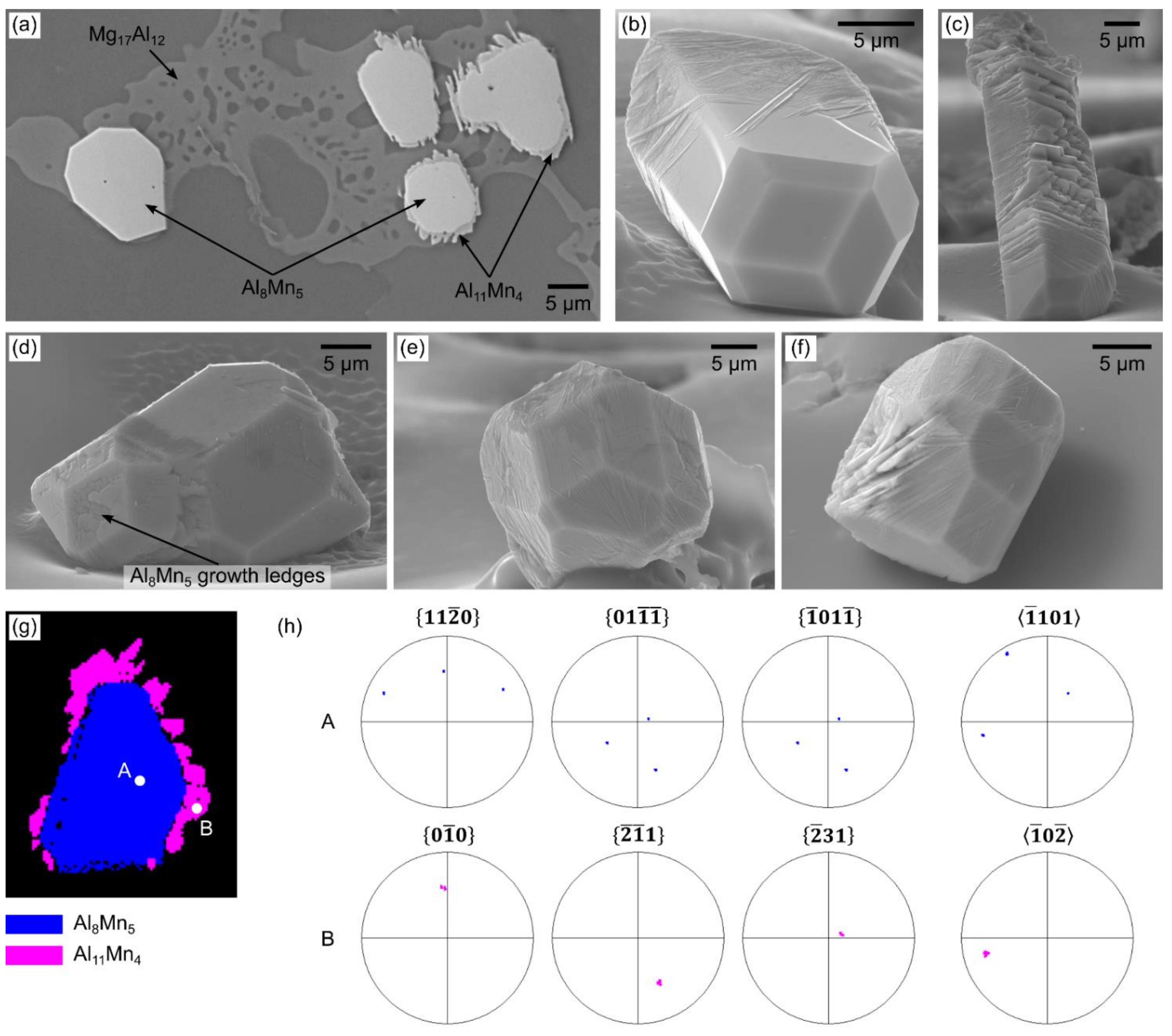
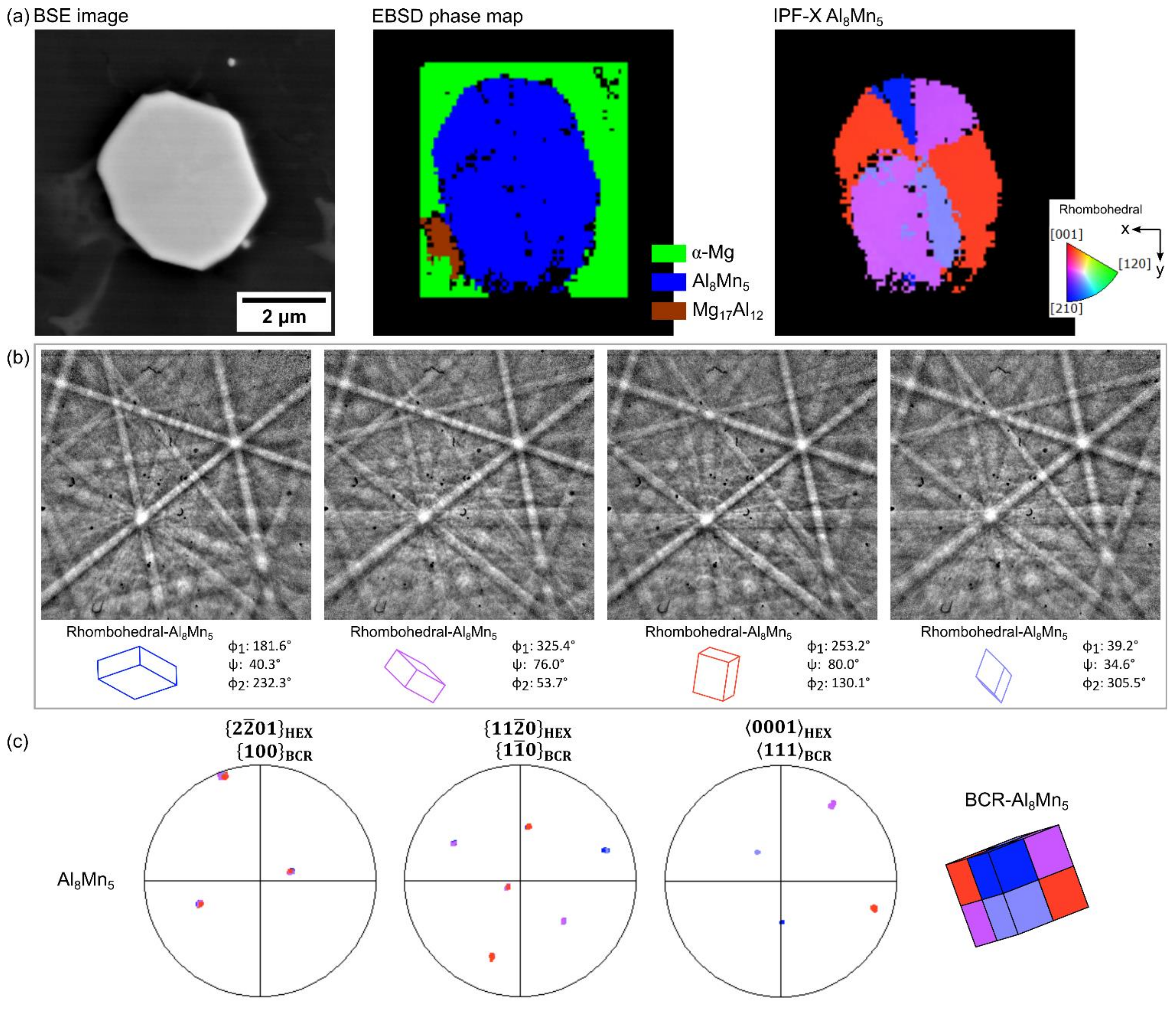
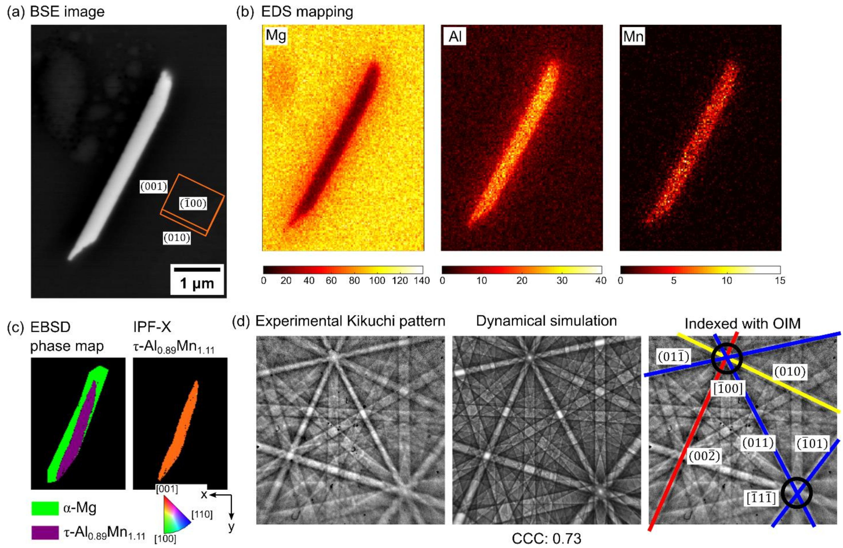
3.1.3. Al11Mn4 Nucleation and Growth on Al8Mn5 during Solidification

The thermodynamic calculations in Figure 2 indicate that Al11Mn4 and Al4Mn should form during solidification. It was found that Al11Mn4 formed on Al8Mn5 when the cooling rate was ~0.1 K/s and was usually absent or only present as traces when the cooling rate was 1 K/s or higher. For example, the sample in Figure 3 was cooled at ~1 K/s and has no Al11Mn4 on its surface. Al4Mn was not detected in this work.
Figure 4 overviews the key features of Al11Mn4 formation on Al8Mn5 during solidification at the slow cooling rate of ~0.1 K/s. Figure 4a shows the common result that the amount of Al11Mn4 on Al8Mn5 varies from particle to particle. The three right-most particles are fully surrounded by Al11Mn4 plates, but the left-most particle has no discernable Al11Mn4 on its surface. The development of Al11Mn4 plates can be understood by examining deep-etched particles with different degrees of Al11Mn4 growth. Figure 4b,c show Al11Mn4 growth on the surface of rods of Al8Mn5. In (b), a thin layer of Al11Mn4 is present on part of the Al8Mn5 surface showing the early stages of growth, whereas in (c), well-developed parallel Al11Mn4 plates are growing around the Al8Mn5 rod. Figure 4d–f show similar results for Al11Mn4 growth on Al8Mn5 equiaxed particles, where an increasing amount of Al11Mn4 is present from (d) to (f) and the thin lines along the surface of particles in (d) and (e) develop into plates such as those in (f).
The Al11Mn4 surrounding Al8Mn5 was usually polycrystalline with multiple reproducible orientation relationships (ORs) to the Al8Mn5 particle. Figure 4g–h gives an example of a commonly found OR in EBSD studies that can be written 11 2 ¯ 0 A l 8 M n 5 1 1 ¯ 0 A l 11 M n 4 and 1 ¯ 101 A l 8 M n 5 1 ¯ 0 2 ¯ A l 11 M n 4 . Note that this OR is one of a family of ORs that formed between Al11Mn4 and Al8Mn5. Further details are given in [29], which also discusses how these ORs relate to the similarities between these triclinic and rhombohedral crystals. The formation of Al11Mn4 on the surface of Al8Mn5 during solidification is consistent with the Scheil solidification reaction sequence in Figure 2b, where the quasi-peritectic reaction L + Al8Mn5 → Al11Mn4 + α-Mg starts at the interface between liquid and Al8Mn5, and then further Al11Mn4 forms during cooling by L → Al11Mn4 + α-Mg.

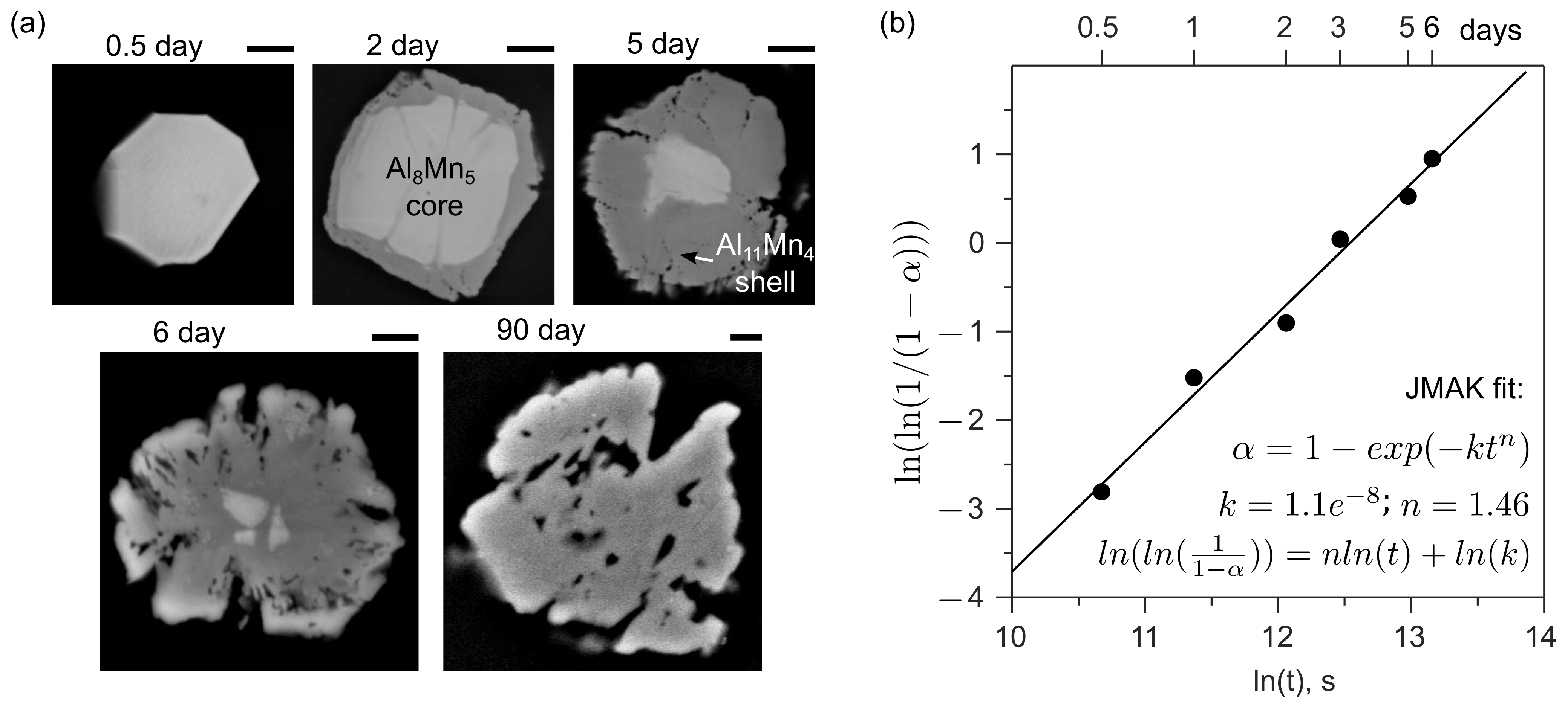
3.1.4. Transformation of Al8Mn5 into Al11Mn4 during Solution Heat Treatment

For the study of Al-Mn phase transformations during solution heat treatment at 410 °C, starting samples were cut from the as-received AZ91 ingot, which contained Al8Mn5 and almost no Al11Mn4 in the as-cast condition. Figure 5a shows typical cross sections of equiaxed Al-Mn particles after different times at 410 °C. The initial Al8Mn5 particles first developed a shell of Al11Mn4. The transformation then proceeded by the growth of the Al11Mn4 shell into the Al8Mn5 core until all Al8Mn5 had transformed in Al11Mn4. It can be seen in Figure 5a that this transformation resulted in significant cracking of the Al11Mn4 phase similar to the findings in recent studies [29,32].
To measure the kinetics of the transformation, the area fractions of Al11Mn4 and Al8Mn5 were measured in at least 100 particles for each heat treatment time and converted into a volume fraction transformed using the method in [29]. The transformation kinetics were then analysed using the Johnson–Mehl–Avrami–Kolmogorov (JMAK) equation in Equation (1), where α is the volume fraction of original Al8Mn5 transformed, and k and n are fitting constants.
α = 1 e k t n
The analysis is plotted in Figure 5b. The data can be well-described by the JMAK equation with an exponent of ~1.5. This is discussed in terms of the solid-state reaction kinetics in core–shell transformations in [29]. A key feature in Figure 5 is that the transformation of Al8Mn5 into Al11Mn4 at 410 °C took approximately one week to complete, which is slow relative to the time to dissolve the Mg17Al12 into α-Mg (approximately one day in these samples).

3.2. Al-Mn IMCs in HPDC AZ91

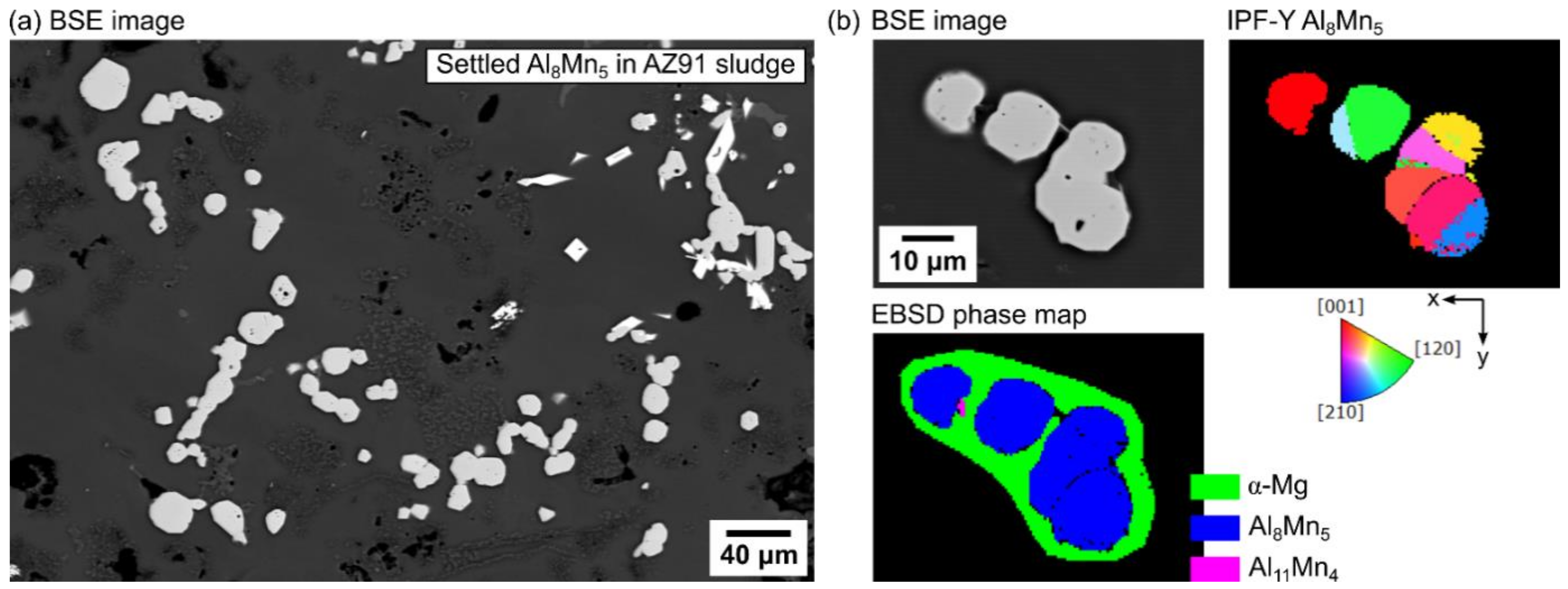
3.2.1. Sludge in Crucible

Direct observation in synchrotron radiography has confirmed that IMC particles can settle to the bottom of crucibles and form a sludge layer during either heating or solidification of AZ91 [28]. Figure 6 shows the SEM examination of a sludge sample from the bottom of an industrial HPDC holding pot of AZ91. It can be seen in Figure 6a that the settled IMC particles were agglomerated and formed clusters. In Figure 6b, the EBSD inspection identified that those IMC particles were Al8Mn5 occasionally with small Al11Mn4 plates on the surface. According to the IPF-Y orientation map, the two isolated Al8Mn5 particles (top left and middle) contain single or two orientations, whereas the agglomerated particle (bottom right) contains multiple orientations. The middle Al8Mn5 particle in the IPF-Y map followed the same twin OR as in Figure 3, although only two orientations were present. In the agglomerated particle, each two orientations (yellow and pink, green and orange, and red and blue) had the twin OR, i.e., three twinned Al8Mn5 were agglomerated. Multiple inspections found that 1–2 orientations were commonly observed in the settled Al8Mn5, and all had the twinned OR even though the number of twinned orientations per particle was less than four (as was typical of Al8Mn5 that was not in a sludge layer such as in Figure 3).

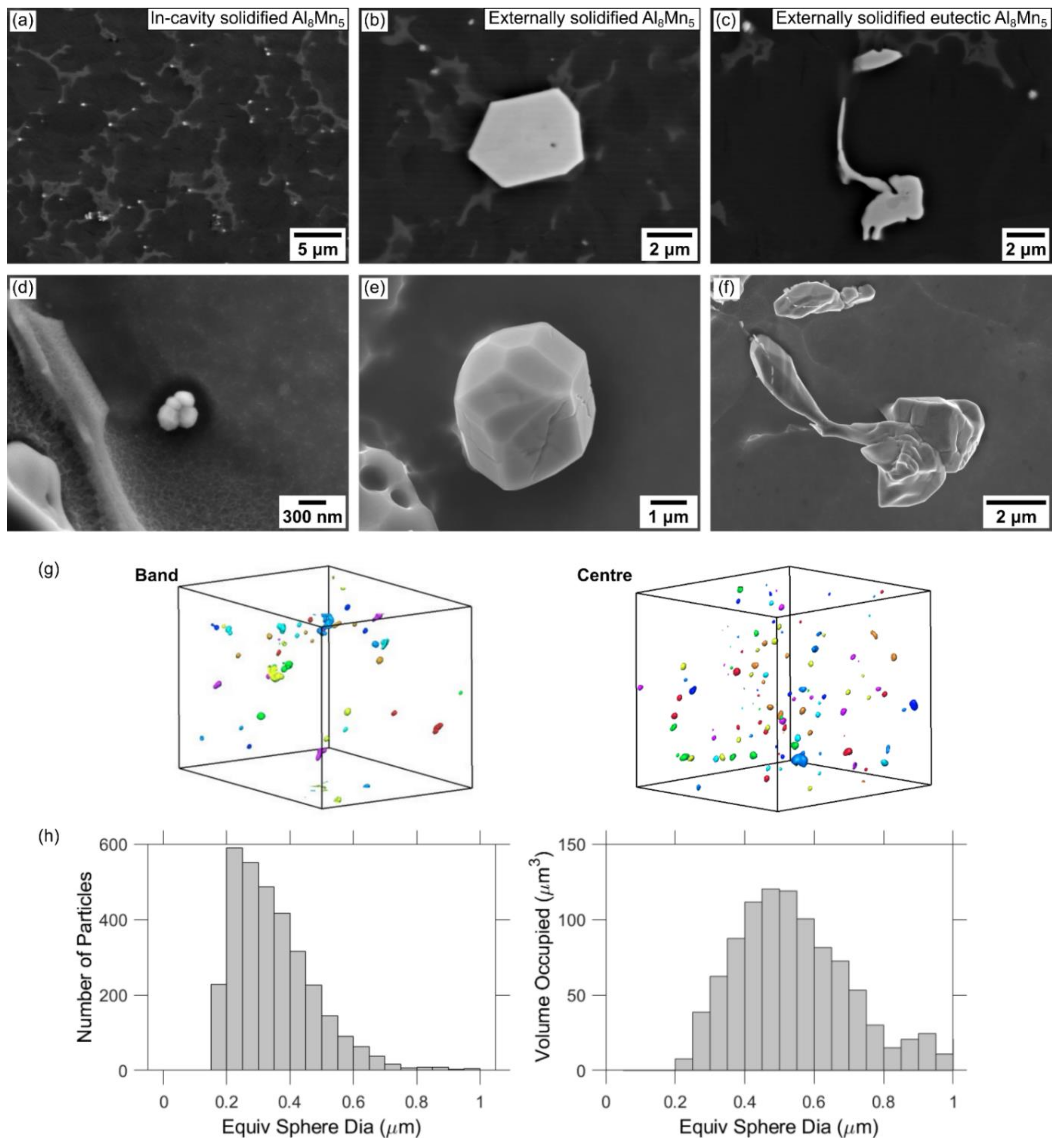
3.2.2. Microstructure Overview

Figure 7 displays the general microstructure of the HPDC AZ91 from the mould in Figure 1b. Figure 7b,c are low magnification optical micrographs of the as-polished and deep-etched cross section. The dark bands in Figure 7b are porosity defect bands [42,43,44,45,46,47,48], and the fine dark networks in Figure 7c,d are regions containing a higher fraction of eutectic Mg17Al12 (positive macrosegregation). The fine eutectic structure can be seen more clearly in the higher magnification SEM images in Figure 7f,g. The α-Mg grains had a complex variety of sizes and morphologies (Figure 7d,e). For example, the EBSD IPF-Y orientation map in Figure 7e contains grains varying in size by more than an order of magnitude.
This has previously been attributed to solidification occurring throughout the different stages of HPDC when the cooling and flow conditions vary significantly, as well as to flow transporting α-Mg grains through the different HPDC stages [47,49,50,51,52]. The large α-Mg dendrites up to ~150 µm in the micrograph and the EBSD IPF-Y orientation map in Figure 7d,e are externally solidified α-Mg crystals (ESCs) that formed in the shot chamber at a low cooling rate before injection in HPDC [49,53,54,55], where the local temperature dropped below ~600 °C (Figure 2). In Figure 7f,g, it can be seen that Al8Mn5 particles in the microstructure also had a wide range of sizes, with the example labelled in (f) being an order of magnitude larger than that labelled in (g). The larger Al8Mn5 particles in these HPDC samples were in the range of 2–5 μm in diameter and have even been reported to be 20 μm long in other HPDC samples [56]. This size range is comparable with Al8Mn5 solidified at a low cooling rate [24], so these larger Al8Mn5 are externally solidified crystals (ESCs) that nucleated and grew in the shot chamber analogous to α-Mg ESCs. This interpretation is also consistent with Al8Mn5 being stable at temperatures above the α-Mg liquidus (Figure 2). In contrast, the nanoscale Al8Mn5 were in-cavity solidified particles owing to the high cooling rate in the die cavity during HPDC.

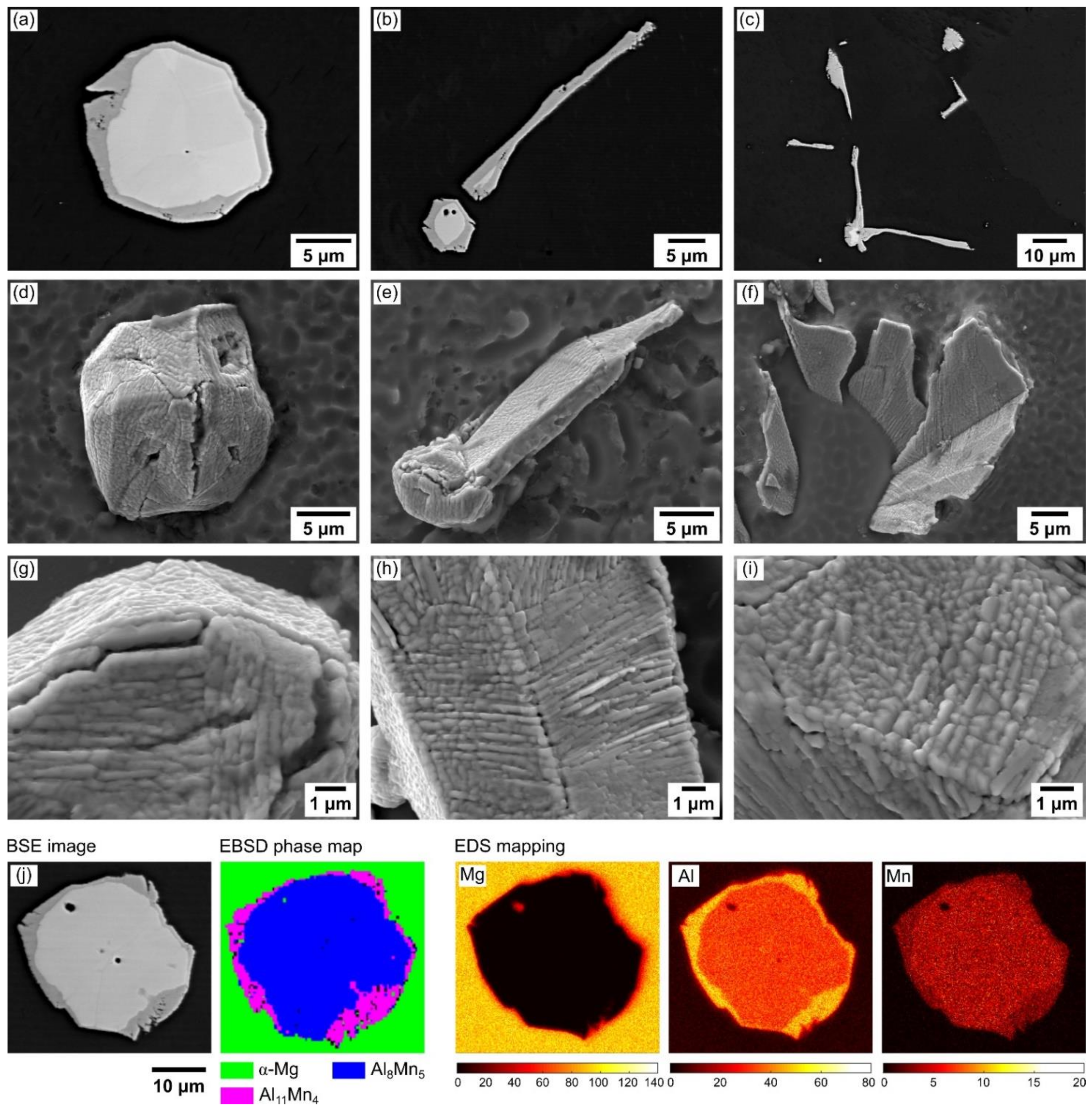
3.2.3. Al-Mn IMC Formation in HPDC AZ91D

Figure 8a–f shows the microstructure of the in-cavity and externally solidified IMCs in the HPDC AZ91. In the cross-section BSE images, the in-cavity solidified Al8Mn5 particles were distributed near the eutectic Mg17Al12 network. They were 200–300 nm particles in size, such as that in Figure 8d. The externally solidified Al8Mn5 particles were equiaxed multifaceted polyhedrons around 2–5 µm and evenly distributed in the α-Mg matrix. In some externally solidified Al8Mn5, the rod-like Al8Mn5 grew from the equiaxed polyhedrons, as illustrated in Figure 8c–f. Figure 8g shows FIB tomography reconstructed images of Al8Mn5 particles in a volume of ~12 × 12 × 12 μm3 at two locations: the defect band and the center of the cross section. Each colour in the reconstructed images represents a unique particle. Figure 8h shows the size distribution of these Al-Mn particles in terms of the number of particles in each size bin and the volume occupied by particles in each size bin, for all studied locations combined. The great majority of particles in the plots are less than 1 μm in diameter, so these are the size distribution of the in-cavity solidified IMCs and there were no ESCs in the volumes sampled. Note that the particle number histogram appears to be truncated on the small diameter side, indicating that there are likely to also be a significant number of IMCs smaller than 200 nm that were not detected by this technique.
The externally solidified Al8Mn5 in Figure 8b had the same cyclic twin OR as in Figure 3 and indeed the particle shown in Figure 3 came from the HPDC AZ91 casting. They all agree with previous research in various Mg-Al-based alloys that Al8Mn5 equiaxed particles are cyclic twins [24,28,29]. The in-cavity solidified Al8Mn5 particles in Figure 8a were examined by EBSD; however, they were too small to give a clear diffraction pattern in those nanoscale particles. Based on the SEM image (Figure 7f) and the FIB tomography (Figure 8h), it can be seen that the in-cavity solidified Al8Mn5 ~200–400 nm were the dominant Al-Mn IMC in the HPDC AZ91, whereas considerably fewer large externally solidified IMCs (Figure 8b,c) were present. Both of them were evenly distributed in the α-Mg matrix shown in the reconstructed images in Figure 8g.
Al11Mn4 was not detected in the HPDC AZ91, probably because the temperature was never low enough in the shot chamber for their formation (Al11Mn4 only becomes stable once ~ 75% of the sample is α-Mg is present according to the calculations in Figure 2), and the cooling rate was too high in the die cavity, which suppressed the formation of Al11Mn4. This is consistent with Al11Mn4 only forming at a low cooling rate (e.g., 0.1 K/s) in the laboratory study in Figure 4.
In addition to Al8Mn5, the metastable phase τ-Al0.89Mn1.11 was occasionally found in the HPDC AZ91, as shown in Figure 9a. τ-Al0.89Mn1.11 formed as a plate. EDS mapping in Figure 9b confirmed only Al and Mn in this phase. From the EBSD phase map and the IPF-X orientation map (Figure 9c), it can be seen that this single-phase plate contains a single orientation. The wire frame unit cell of τ-Al0.89Mn1.11 was plotted on the BSE image using the EBSD-measured Euler angles. To test this phase further, the experimental Kikuchi pattern and a dynamical simulated pattern were compared, as shown in Figure 9d. Band by band inspection and the high cross-correlation coefficient (ccc) confirm a good agreement with the crystal structure. Lattice planes and directions were indexed on the Kikuchi pattern by OIM software and the selected ones are labelled.
Past work [25,26,27] has reported metastable τ-Al0.89Mn1.11 in Mg-Al alloys with lower Al content (often in AZ31 [25,27]) and it was never found in our laboratory cast AZ91 cooled at 0.1 K/s or 1 K/s. It seems that the high in-cavity cooling rate of HPDC plays an important role in enabling the formation of the metastable τ-Al0.89Mn1.11 in AZ91. At the same time, we note that almost all Al-Mn particles in the HPDC bars were Al8Mn5, and that τ-Al0.89Mn1.11 was very rare and was only found because it drew our attention with its different shape.

3.3. Al-Mn IMCs in DC-Cast AZ80A

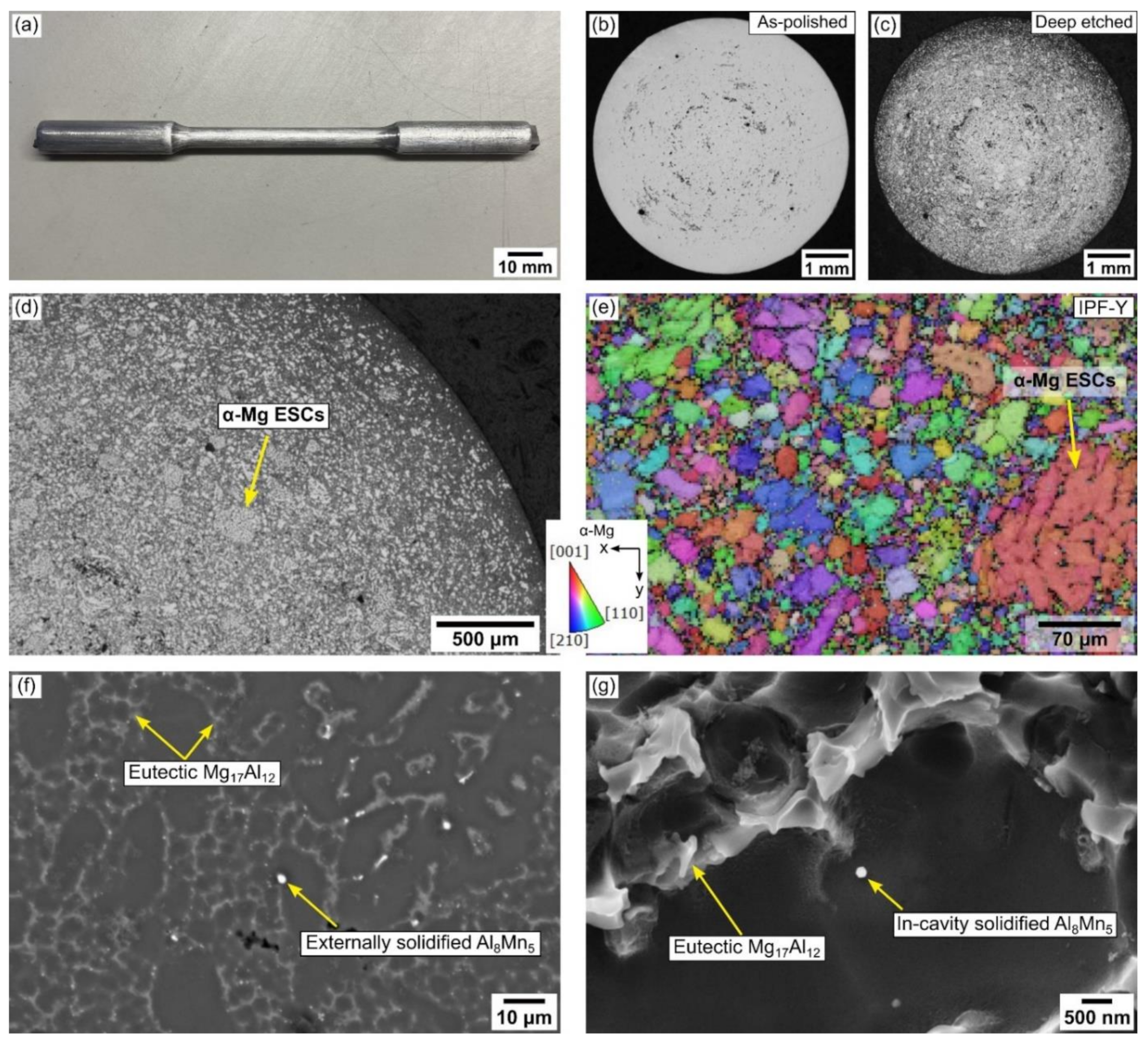
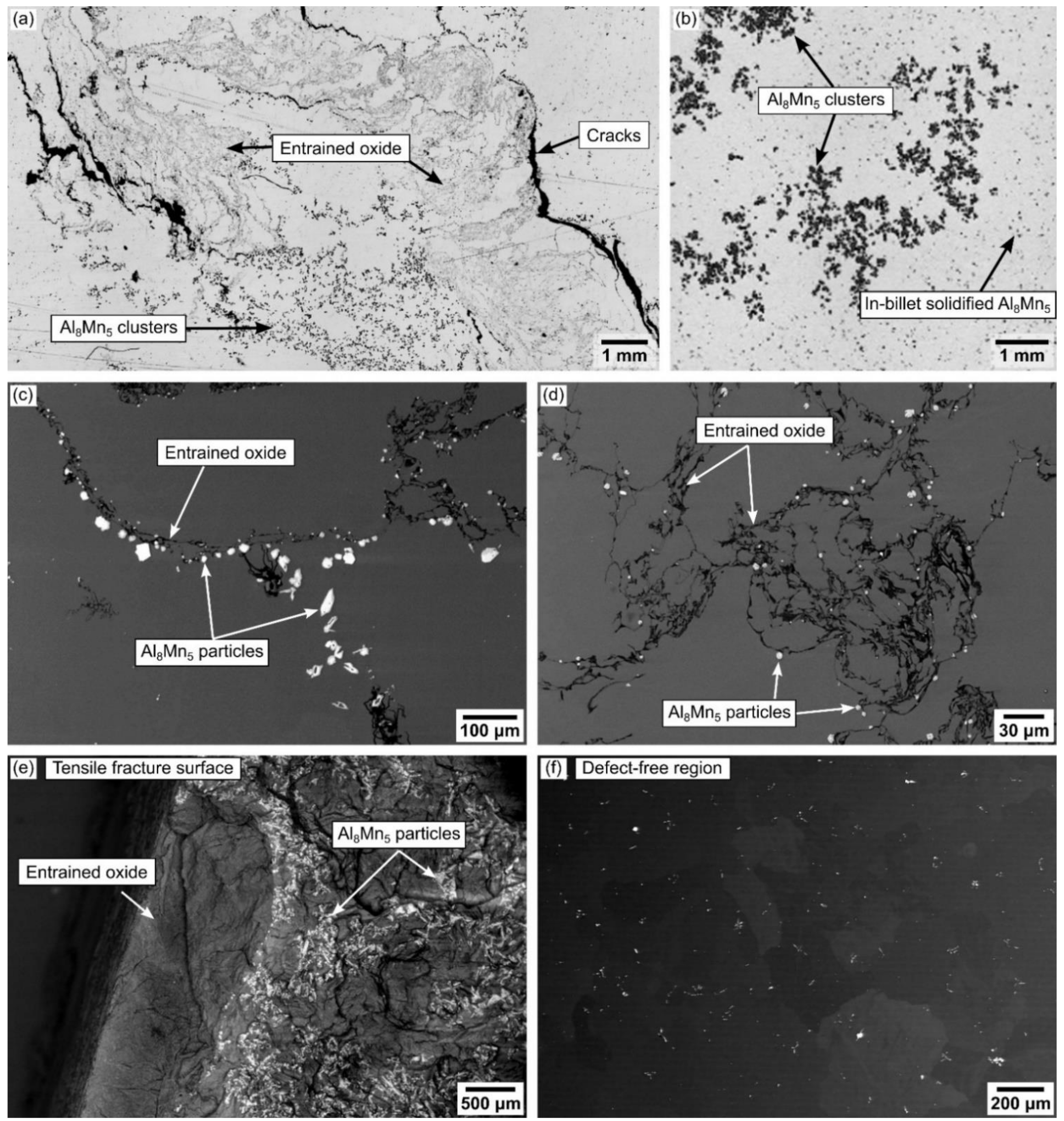
3.3.1. Microstructure of Defect and Defect-Free Region

Past work has shown that large entrained oxide films with numerous intermetallic particles attached can form as a severe defect in DC cast billets of AZ80 [21] if pouring and filtration are not well controlled. Figure 10a–d shows such defects in the AZ80A billet studied here in low magnification optical microscope images (a,b) and higher magnification BSE images (c,d). The defects involve a combination of entrained oxide, clusters of Al8Mn5 particles and cracks, and are normally located near the center of the AZ80 billet. In Figure 10a, the cracks initiate from the oxide films as is typical of oxide bifilms [57,58,59,60,61] where one side of the film remains unbonded due to the entrainment process and opens when the liquid pressure decreases due to solidification shrinkage [62]. Figure 10a also shows that large Al8Mn5 particles are clustered near the entrained oxide. In Figure 10b, note that the IMC particles in the clusters were considerably larger than the typical IMC particles in other parts of the billet. From Figure 10c,d, it can be seen that almost all Al8Mn5 particles are touching the entrained oxide and are around 2–60 μm in size.
The mechanisms by which numerous Al8Mn5 particles become attached to the entrained oxide have recently been explored in a synchrotron X-ray radiography study that directly observed settling Al8Mn5 particles interacting with entrained oxides [28]. It was clearly observed that the entrained oxide can act as a filter and trap the Al8Mn5 particles as they settle. There were also possible sightings of entrained oxide acting as a nucleation site for some Al8Mn5 particles. The formation of defects in the DC-cast AZ80 in Figure 10a–d is likely to have been by similar mechanisms. The oxide films were likely produced during melt pouring/handling and entrained into the melt. The relatively large size of Al8Mn5 in Figure 10b,c indicates that the Al8Mn5 started forming in the launder system where the temperature dropped below ~640 °C (Figure 2), and were subsequently trapped by the entrained oxide in settling or flow and transported into the DC mould, leading to clusters of large IMCs such as in Figure 10a. In contrast, the Al8Mn5 particles that nucleated and grew independently in the DC casting mould had a faster cooling rate, giving smaller size IMCs similar to Figure 10c or Figure 10d.
Tensile testing of the AZ80 samples containing such defects gave a fracture surface along the entrained oxide shown in Figure 10e with a large number of clustered Al8Mn5 particles also visible on the fracture surface. Such combined oxide and Al8Mn5 cluster defects are identifiable by ultrasonic inspection and so can be sectioned from billets prior to forging. However, this cracking can be avoided by preventing oxide entrainment during DC casting. This requires improved pouring and/or better filters to capture entrained oxides in the launder system.
Figure 10f overviews the microstructure of a normal region of the AZ80 billet shown in Figure 1c. Compared with Figure 10a–e, it can be seen that the Al-Mn IMCs were evenly distributed in the α-Mg matrix when entrained oxide was absent. Note that eutectic Mg17Al12 was absent at the grain boundaries as the AZ80 has been solution heat-treated.

3.3.2. Microstructure of Al-Mn IMCs in Heat-Treated DC-Cast AZ80A

Figure 11 shows the typical microstructure of the Al-Mn IMCs in DC-cast AZ80 (Figure 10f) in the solution heat-treated condition. Note that this section refers to normal DC cast billet that does not contain large, entrained oxide and clustered IMCs. Three morphologies of IMC were present: equiaxed polyhedral particles, hexagonal rods, and plates, shown in Figure 11a–c, respectively. In these IMC particles, two shades of grey can be clearly seen in the BSE images that were consistent with Al8Mn5 surrounded by Al11Mn4 based on EBSD. Figure 11d–f reveals the 3D shape of the IMCs after α-Mg was selectively dissolved away. The appearance of Al11Mn4 is similar to that formed by solid-state transformation in the laboratory study in Figure 5a, indicating that the Al11Mn4 in DC cast AZ80 mostly formed during solutionizing. Figure 11g–i are high magnification images showing the details of the transformation phase, which consists of numerous Al11Mn4 plates with nanoscale width covering the surface of Al8Mn5. Figure 11j exhibits an EBSD phase map and EDS mapping of the cross section of an IMC particle confirming that Al8Mn5 phase was partially transformed to Al11Mn4.
From Figure 11j, it is clear that the solid-state transformation is at a relatively early stage after solution heat treatment. This is consistent with the kinetics of the Al8Mn5 transformation into Al11Mn4 in the laboratory study in Figure 5b, where a solutionizing time of 12 or 24 h gives a calculated fraction transformed of only 0.06–0.16. Thus, solutionizing after DC casting produces a microstructure of α-Mg and core–shell particles of Al8Mn5 surrounded by a layer of Al11Mn4.

4. Conclusions

The microstructure of Al-Mn IMCs has been overviewed in laboratory cast AZ91 with a cooling rate of ~0.1 and 1 K/s. Al8Mn5 formed as cyclic twinned equiaxed polyhedral particles with multiple facets or, more rarely, as rods and plates. Al11Mn4 nucleated and grew on the Al8Mn5 surface as plates late during solidification. Al11Mn4 was promoted by slow cooling rates with significantly more Al11Mn4 forming at 0.1 K/s that 1 K/s. During solution heat treatment, Al8Mn5 transformed into Al11Mn4 by the growth of a Al11Mn4 shell into the Al8Mn5 core until all Al8Mn5 had transformed.
The HPDC AZ91 sludge from the bottom of the holding pot comprised of settled and agglomerated Al8Mn5 particles. These were either single crystal or twinned in the same manner as cyclic twins. The Al8Mn5 in HPDC AZ91D had similar features as in the slow cooled laboratory AZ91 sample, but the particles had a much wider size range owing to the different cooling rates in the shot chamber and die cavity. The in-cavity solidified Al8Mn5 were ~200–400 nm, whereas the externally solidified Al8Mn5 were ~2–5 μm. The in-cavity solidified Al8Mn5 particles were the majority of Al-Mn IMC in the HPDC AZ91D. The high cooling rate in HPDC suppressed the formation Al11Mn4, but enabled the formation of a small amount of metastable τ-Al0.89Mn1.11.
The section of DC-cast AZ80A billet has been identified to contain a large entrained oxide by prior ultrasonic inspection. It was found that this entrained oxide had large clusters of IMC particles attached. Comparing with recent X-ray imaging experiments, it is likely that the formation mechanism of these clusters is related to the transport in the launder system, where Al8Mn5 particles are carried in the flow and become trapped by the entrained oxide. It is also possible that some Al8Mn5 particles nucleated on the oxide. Improved pouring and filtration are required to prevent these entrained oxide and large particles from entering the DC-casting.
In the DC-cast AZ80A, regions of microstructure free from large entrained oxides contained smaller Al-Mn particles that were more evenly distributed. These had a similar size to the laboratory AZ91 samples. Owing to the solution heat treatment, Al8Mn5 had partially transformed into Al11Mn4 to produce core–shell particles. The Al11Mn4 shell consisted of plates with nanoscale width covering the surface of Al8Mn5. This partial transformation was at a relatively early stage of transformation, which is consistent with the slow kinetics measured in the laboratory study, where it took approximately one week for the reaction to complete.

Author Contributions

Conceptualization, L.P. and C.M.G.; methodology, L.P. and C.M.G.; software, J.X.; validation, L.P., G.Z., D.W., J.X. and C.M.G.; formal analysis, L.P., G.Z., D.W. and J.X.; investigation, L.P., G.Z. and J.X.; resources, G.Z., S.J., H.Z. and C.M.G.; data curation, L.P.; writing—original draft preparation, L.P.; writing—review and editing, C.M.G.; visualization, L.P., D.W., G.Z. and J.X.; supervision, C.G; project administration, C.M.G.; funding acquisition, G.Z. and C.M.G. All authors have read and agreed to the published version of the manuscript.

Funding

This research was funded by Engineering and Physical Sciences Research Council (EPSRC, UK), grant number EP/N007638/1 (the Future LiME Hub), and partly supported by the National Natural Science Foundation of China, grant number 51904352.

Institutional Review Board Statement

Not applicable.

Informed Consent Statement

Not applicable.

Data Availability Statement

The data presented in this study are available on request from the corresponding author.

Acknowledgments

We gratefully acknowledge the use of characterisation facilities within the Harvey Flower Electron Microscopy Suite, Department of Materials, Imperial College London. We thank Mark Turski of Magnesium Elektron for providing the DC cast forging billet. Financial support from EPSRC (UK) under grant number EP/N007638/1 (the Future LiME Hub) is gratefully acknowledged. This work was partly supported by the National Natural Science Foundation of China (51904352).

Conflicts of Interest

The authors declare no conflict of interest.

References

  1. Blawert, C.; Hort, N.; Kainer, K. Automotive applications of magnesium and its alloys. Trans. Indian Inst. Met. 2004, 57, 397–408. [Google Scholar]
  2. Luo, A.A. Magnesium casting technology for structural applications. J. Magnes. Alloys 2013, 1, 2–22. [Google Scholar] [CrossRef] [Green Version]
  3. Brady, M.P.; Joost, W.J.; Warren, C.D. Insights from a recent meeting: Current status and future directions in magnesium corrosion research. Corrosion 2017, 73, 452–462. [Google Scholar] [CrossRef]
  4. Weiler, J. A review of magnesium die-castings for closure applications. J. Magnes. Alloys 2019, 7, 297–304. [Google Scholar] [CrossRef]
  5. American Society for Testing and Materials, ASTM. B94-18, Standard Specification for Magnesium-Alloy Die Castings; ASTM-International: West Conshohocken, PA, USA, 2018. [Google Scholar]
  6. American Society for Testing and Materials, ASTM. B80-15, Standard Specification for Magnesium-Alloy Sand Castings; ASTM-International: West Conshohocken, PA, USA, 2015. [Google Scholar]
  7. American Society for Testing and Materials, ASTM. B403-20, Standard Specification for Magnesium-Alloy Investment Castings; ASTM-International: West Conshohocken, PA, USA, 2020. [Google Scholar]
  8. American Society for Testing and Materials, ASTM. B91-17, Standard Specification for Magnesium-Alloy Forgings; ASTM-International: West Conshohocken, PA, USA, 2017. [Google Scholar]
  9. Agnew, S.R. Wrought magnesium: A 21st century outlook. JOM 2004, 56, 20–21. [Google Scholar] [CrossRef]
  10. He, H.; Huang, S.; Yi, Y.; Guo, W. Simulation and experimental research on isothermal forging with semi-closed die and multi-stage-change speed of large AZ80 magnesium alloy support beam. J. Mater. Process. Technol. 2017, 246, 198–204. [Google Scholar] [CrossRef]
  11. American Society for Testing and Materials, ASTM. B90-21, Standard Specification for Magnesium-Alloy Sheet and Plate; ASTM-International: West Conshohocken, PA, USA, 2021. [Google Scholar]
  12. Song, G.L.; Atrens, A. Corrosion mechanisms of magnesium alloys. Adv. Eng. Mater. 1999, 1, 11–33. [Google Scholar] [CrossRef]
  13. Lunder, O.; Nordien, J.; Nisancioglu, K. Corrosion resistance of cast Mg-Al alloys. Corros. Rev. 1997, 15, 439–470. [Google Scholar] [CrossRef]
  14. Hanawalt, J. Corrosion studies of magnesium and its alloys. Trans. AIME 1942, 147, 273–299. [Google Scholar]
  15. Hanawalt, J.D.; Nelson, C.E.; Holdeman, G.E. Removal of iron from magnesiumbase alloys. U.S. Patent 2267862A, 30 December 1941. [Google Scholar]
  16. Esmaily, M.; Svensson, J.; Fajardo, S.; Birbilis, N.; Frankel, G.; Virtanen, S.; Arrabal, R.; Thomas, S.; Johansson, L. Fundamentals and advances in magnesium alloy corrosion. Prog. Mater. Sci. 2017, 89, 92–193. [Google Scholar] [CrossRef]
  17. Lunder, O.; Nisancioglu, K.; Hansen, R.S. Corrosion of Die Cast Magnesium-Aluminum Alloys; 0148-7191; SAE Technical Paper: 930755; SAE International: Warrendale, PA, USA, March 1993. [Google Scholar]
  18. Zeng, R.-C.; Zhang, J.; Huang, W.-J.; Dietzel, W.; Kainer, K.; Blawert, C.; Ke, W. Review of studies on corrosion of magnesium alloys. Trans. Nonferrous Met. Soc. China 2006, 16, s763–s771. [Google Scholar] [CrossRef]
  19. Pawar, S.; Zhou, X.; Thompson, G.; Scamans, G.; Fan, Z. The role of intermetallics on the corrosion initiation of twin roll cast AZ31 Mg alloy. J. Electrochem. Soc. 2015, 162, C442–C448. [Google Scholar] [CrossRef]
  20. Sarvesha, R.; Chalapathi, D.; Yadava, M.; Jain, J.; Singh, S. In-situ studies on deformation and fracture characteristics of AZ91 Mg alloy. Materialia 2021, 18, 101177. [Google Scholar] [CrossRef]
  21. Mackie, D.; Robson, J.; Withers, P.; Turski, M. Characterisation and modelling of defect formation in direct-chill cast AZ80 alloy. Mater. Charact. 2015, 104, 116–123. [Google Scholar] [CrossRef]
  22. Zeng, G.; Nogita, K.; Belyakov, S.; Xian, J.; McDonald, S.; Yang, K.; Yasuda, H.; Gourlay, C. Real-Time Observation of AZ91 Solidification by Synchrotron Radiography. In Magnesium Technology 2017; Springer: Berlin/Heidelberg, Germany, 2017; pp. 597–603. [Google Scholar]
  23. Zeng, G.; Xian, J.; Gourlay, C. Growth of Al8Mn5 Intermetallic in AZ91. In Magnesium Technology 2017; Springer: Berlin/Heidelberg, Germany, 2017; pp. 85–92. [Google Scholar]
  24. Zeng, G.; Xian, J.; Gourlay, C. Nucleation and growth crystallography of Al8Mn5 on B2-Al (Mn, Fe) in AZ91 magnesium alloys. Acta Mater. 2018, 153, 364–376. [Google Scholar] [CrossRef] [Green Version]
  25. Han, G.; Ma, G.; Liu, X. Effect of manganese on the microstructure of Mg–3Al alloy. J. Alloy Compd. 2009, 486, 136–141. [Google Scholar] [CrossRef]
  26. Han, G.; Liu, X. Phase control and formation mechanism of Al–Mn (–Fe) intermetallic particles in Mg–Al-based alloys with FeCl 3 addition or melt superheating. Acta Mater. 2016, 114, 54–66. [Google Scholar] [CrossRef]
  27. Yao, S.; Liu, S.; Zeng, G.; Li, X.; Lei, T.; Li, Y.; Du, Y. Effect of manganese on microstructure and corrosion behavior of the Mg-3Al alloys. Metals 2019, 9, 460. [Google Scholar] [CrossRef] [Green Version]
  28. Peng, L.; Zeng, G.; Su, T.; Yasuda, H.; Nogita, K.; Gourlay, C. Al8Mn5 Particle Settling and Interactions with Oxide Films in Liquid AZ91 Magnesium Alloys. JOM 2019, 71, 2235–2244. [Google Scholar] [CrossRef] [Green Version]
  29. Xian, J.; Peng, L.; Zeng, G.; Wang, D.; Gourlay, C. Al11Mn4 formation on Al8Mn5 during the solidification and heat treatment of AZ-series magnesium alloys. Materialia 2021, 19, 101192. [Google Scholar] [CrossRef]
  30. Chen, T.; Yuan, Y.; Liu, T.; Li, D.; Tang, A.; Chen, X.; Schmid-Fetzer, R.; Pan, F. Effect of Mn Addition on Melt Purification and Fe Tolerance in Mg Alloys. JOM 2021, 73, 892–902. [Google Scholar] [CrossRef]
  31. Sarvesha, R.; Alam, W.; Gokhale, A.; Guruprasad, T.; Bhagavath, S.; Karagadde, S.; Jain, J.; Singh, S. Quantitative assessment of second phase particles characteristics and its role on the deformation response of a Mg-8Al-0.5 Zn alloy. Mater. Sci. Eng. A 2019, 759, 368–379. [Google Scholar] [CrossRef]
  32. Sarvesha, R.; Thirunavukkarasu, G.; Chiu, Y.L.; Jones, I.P.; Jain, J.; Singh, S. A study on the phase transformation of γ2-Al8Mn5 to LT-Al11Mn4 during solutionizing in AZ91 alloy. J. Alloy Compd. 2021, 873, 159836. [Google Scholar] [CrossRef]
  33. Sarvesha, R.; Bhagyaraj, J.; Bhagavath, S.; Karagadde, S.; Jain, J.; Singh, S. 2D and 3D characteristics of intermetallic particles and their role in fracture response of AZ91 magnesium alloy. Mater. Charact. 2021, 171, 110733. [Google Scholar] [CrossRef]
  34. Peng, L.; Zeng, G.; Xian, J.; Gourlay, C.M. Al–Mn–Fe intermetallic formation in AZ91 magnesium alloys: Effects of impurity iron. Intermetallics 2022, 142, 110733. [Google Scholar] [CrossRef]
  35. Gryguc, A.; Shaha, S.K.; Behravesh, S.B.; Jahed, H.; Wells, M.; Williams, B.; Su, X. Monotonic and cyclic behaviour of cast and cast-forged AZ80 Mg. Int. J. Fatigue 2017, 104, 136–149. [Google Scholar] [CrossRef] [Green Version]
  36. Owen, E.; Pickup, L.; Roberts, I. Lattice constants of five elements possessing hexagonal structure. Z. Krist. Cryst. Mater. 1935, 91, 70–76. [Google Scholar] [CrossRef]
  37. Thimmaiah, S.; Tener, Z.; Lamichhane, T.N.; Canfield, P.C.; Miller, G.J. Crystal structure, homogeneity range and electronic structure of rhombohedral γ-Mn5Al8. Z. Krist. Cryst. Mater. 2017, 232, 601–610. [Google Scholar] [CrossRef] [Green Version]
  38. Kontio, A.; Stevens, E.; Coppens, P.; Brown, R.; Dwight, A.; Williams, J. New investigation of the structure of Mn4Al11. Acta Crystallogr. B Struct. Crystallogr. Cryst. Chem. 1980, 36, 435–436. [Google Scholar] [CrossRef]
  39. Braun, P.B.; Goedkoop, J.A. An x-ray and neutron diffraction investigation of the magnetic phase Al0.89Mn1.11. Acta Crystallogr. 1963, 16, 737–740. [Google Scholar] [CrossRef]
  40. Schobinger-Papamantellos, P.; Fischer, P. Neutronenbeugungsuntersuchung der Atomverteilung von Mg17Al12. Die Naturwissenschaften 1970, 57, 128–129. [Google Scholar] [CrossRef]
  41. Ellner, M. The structure of the high-temperature phase MnAl (h) and the displacive transformation from MnAl(h) into Mn5Al8. Metall. Trans. A 1990, 21, 1669–1672. [Google Scholar] [CrossRef]
  42. Sannes, S.; Westengen, H. The Influence of Process Conditions on the Microstructure and Mechanical Properties of Magnesium Die Castings. In Proceedings of the International conference and exhibition: Magnesium alloys and their applications, Wolfsburg, Germany, 28–30 April 1998; pp. 223–228. [Google Scholar]
  43. Dahle, A.; Sannes, S.; John, D.S.; Westengen, H. Formation of defect bands in high pressure die cast magnesium alloys. J. Light Met. 2001, 1, 99–103. [Google Scholar] [CrossRef]
  44. Fan, Z.; Liu, G.; Wang, Y. Microstructure and mechanical properties of rheo-diecast AZ91D magnesium alloy. J. Mater. Sci. 2006, 41, 3631–3644. [Google Scholar] [CrossRef]
  45. Cao, H.; Wessén, M. Characteristics of microstructure and banded defects in die cast AM50 magnesium components. Int. J. Cast Met. Res. 2005, 18, 377–384. [Google Scholar] [CrossRef]
  46. Cáceres, C.; Poole, W.; Bowles, A.; Davidson, C. Section thickness, macrohardness and yield strength in high-pressure diecast magnesium alloy AZ91. Mater. Sci. Eng. A 2005, 402, 269–277. [Google Scholar] [CrossRef]
  47. Gourlay, C.; Laukli, H.; Dahle, A. Defect band characteristics in Mg-Al and Al-Si high-pressure die castings. Metall. Mater. Trans. A 2007, 38, 1833–1844. [Google Scholar] [CrossRef]
  48. Li, X.; Yu, W.; Wang, J.; Xiong, S. Influence of melt flow in the gating system on microstructure and mechanical properties of high pressure die casting AZ91D magnesium alloy. Mater. Sci. Eng. A 2018, 736, 219–227. [Google Scholar] [CrossRef]
  49. Bowles, A.; Nogita, K.; Dargusch, M.; Davidson, C.; Griffiths, J. Grain size measurements in Mg-Al high pressure die castings using electron back-scattered diffraction (EBSD). Mater. Trans. 2004, 45, 3114–3119. [Google Scholar] [CrossRef] [Green Version]
  50. Yang, K.V.; Easton, M.A.; Caceres, C.H. The development of the skin in HPDC Mg–Al alloys. Mater. Sci. Eng. A 2013, 580, 191–195. [Google Scholar] [CrossRef]
  51. Yu, W.; Cao, Y.; Li, X.; Guo, Z.; Xiong, S. Determination of interfacial heat transfer behavior at the metal/shot sleeve of high pressure die casting process of AZ91D alloy. J. Mater. Sci. Technol. 2017, 33, 52–58. [Google Scholar] [CrossRef]
  52. Wang, L.; Nguyen, T.; Savage, G.; Davidson, C. Thermal and flow modelling of ladling and injection in high pressure die casting process. Int. J. Cast Met. Res. 2003, 16, 409–417. [Google Scholar] [CrossRef]
  53. Li, X.-b.; Xiong, S.; Guo, Z.-p. On the porosity induced by externally solidified crystals in high-pressure die-cast of AM60B alloy and its effect on crack initiation and propagation. Mater. Sci. Eng. A 2015, 633, 35–41. [Google Scholar] [CrossRef]
  54. Bi, C.; Xiong, S.; Li, X.; Guo, Z. Development of a fluid-particle model in simulating the motion of external solidified crystals and the evolution of defect bands in high-pressure die casting. Metall. Mater. Trans. B 2016, 47, 939–947. [Google Scholar] [CrossRef]
  55. Li, X.-b.; Xiong, S.; Guo, Z.-p. Improved mechanical properties in vacuum-assist high-pressure die casting of AZ91D alloy. J. Mater. Process. Technol. 2016, 231, 1–7. [Google Scholar] [CrossRef]
  56. Zeng, G.; Zhu, X.; Ji, S.; Gourlay, C. The Morphology and Distribution of Al8Mn5 in High Pressure Die Cast AM50 and AZ91. In Magnesium Technology 2018, TMS 2018, Proceedings of the TMS Annual Meetings & Exhibition, Phoenix, AZ, USA, 11–15 March 2018; The Minerals, Metals & Materials Series; Orlov, D., Joshi, V., Solanki, K., Neelameggham, N., Eds.; Springer: Cham, Switzerland, 2018; pp. 137–144. [Google Scholar]
  57. Griffiths, W.; Lai, N.-W. Double oxide film defects in cast magnesium alloy. Metall. Mater. Trans. A 2007, 38, 190–196. [Google Scholar] [CrossRef]
  58. Mirak, A.; Divandari, M.; Boutorabi, S.; Campbell, J. Oxide film characteristics of AZ91 magnesium alloy in casting conditions. Int. J. Cast Met. Res. 2007, 20, 215–220. [Google Scholar] [CrossRef]
  59. Wang, L.; Rhee, H.; Felicelli, S.D.; Sabau, A.S.; Berry, J.T. Oxide Film and Porosity Defects in Magnesium Alloy AZ91. In Proceedings of the Shape Casting: 3rd International Symposium, San Francisco, CA, USA, 15–19 February 2009; p. 348. [Google Scholar]
  60. Mirak, A.; Divandari, M.; Boutorabi, S.; Taylor, J. Effect of oxide film defects generated during mould filling on mechanical strength and reliability of magnesium alloy castings (AZ91). Int. J. Cast Met. Res. 2012, 25, 188–194. [Google Scholar] [CrossRef]
  61. Li, T.; Davies, J.; Zhu, X. Effect of carrier gases on the entrainment defects within AZ91 alloy castings. J. Magnes. Alloy 2021. [Google Scholar] [CrossRef]
  62. Campbell, J. Castings; Elsevier: Amsterdam, The Netherlands, 2003. [Google Scholar]
Figure 1. (a) Composition range of Al and Zn in selected high-purity AZ-series alloys—AZ31B, AZ61A, AZ80A, and AZ91D from ASTM standards [5,8,11]. Black circle and square mark the composition of (b) the HPDC AZ91D and (c) the DC-cast AZ80A used in this study, respectively.
Metals 12 00266 g001
Figure 2. (a) Mg-rich corner of the Mg-Al-Mn liquidus projection calculated in Thermo-Calc software with the TCMG4.0 database. Coloured lines show the change in liquid composition during solidification of Mg-8.95Al-0.19Mn (wt.%). (b) Development of solid phases during solidification assuming equilibrium and the Scheil model. Colour indicates the solidification reactions in (a,b). ‘*’ indicates the reaction L + Al8Mn5 → α-Mg + Al11Mn4 during equilibrium solidification.
Metals 12 00266 g002
Figure 3. Typical cyclic twinned Al8Mn5 particle. This example is from the HPDC AZ91D. Similar particles formed in laboratory cast samples. (a) BSE image, EBSD phase map, and IPF-X orientation map. (b,c) Experimental Kikuchi patterns from the four orientations; selected pole figures showing the cyclic twin OR of Al8Mn5 and the 100 B C R interface; unit cell wireframes of four orientations in the Al8Mn5 cyclic twin from the measured Euler angles.
Metals 12 00266 g003
Figure 4. (a) 2D section showing Al11Mn4 formed on Al8Mn5 crystals during solidification with a cooling rate of ~0.1K/s. (b,c) Al11Mn4 growth on Al8Mn5 rods. (df) Different stages of Al11Mn4 growth on cyclic twinned Al8Mn5 particles (from traces to fully-covered). N.B. Al8Mn5 growth ledges are also visible. (g) EBSD phase map of an Al8Mn5 particle with Al11Mn4. (h) Pole figures of selected planes and directions showing the OR between Al8Mn5 (A) and Al11Mn4 (B).
Metals 12 00266 g004
Figure 5. (a) Typical microstructures of solid-state transformation from Al8Mn5 to Al11Mn4 up to 90 days. (b) Transformation kinetics fitted with JMAK fit. Note that all scale bars in (a) represent 2 μm.
Metals 12 00266 g005
Figure 6. (a) Settled Al8Mn5 particles in the AZ91 sludge at the bottom of crucible. (b) EBSD phase map and IPF-Y orientation map of settled Al8Mn5 particles.
Metals 12 00266 g006
Figure 7. (a) HPDC AZ91 bar from Figure 1b. (b,c) Optical micrographs of the as-polished and deep-etched HPDC AZ91 showing the defects and the fine eutectic structure. (d,e) Externally solidified large α-Mg grain in (c) optical micrograph and (e) EBSD IPF-Y orientation map. (f,g) SE images of the eutectic Mg17Al12 and Al8Mn5 particles.
Metals 12 00266 g007
Figure 8. (ac) Typical microstructure of the Al-Mn IMCs in HPDC-AZ91. (df) Deep-etched image showing the 3D morphology of the Al-Mn IMCs. (g,h) FIB tomography for Al8Mn5 particle size at band and center location in the HPDC sample. (g) FIB tomography rendered images of Al8Mn5 particles in a volume of ~12 × 12 × 12 μm3 at the defect band and the center of the cross section. Each particle has a unique colour. (h) Number of Al8Mn5 particles and volume occupation against Al8Mn5 particle size in all studied volumes.
Metals 12 00266 g008
Figure 9. (a) BSE image of the meta-stable phase τ-Al0.89Mn1.11 in the HPDC AZ91. (b) EDS mapping, (c) EBSD phase map and IPF-X orientation map of the phase. (d) Experimental Kikuchi pattern and dynamical simulation with cross-correlation coefficient (ccc) and indexed crystal planes and directions.
Metals 12 00266 g009
Figure 10. (a,b) Optical micrographs of a large entrained oxide with clustered Al-Mn IMCs at the center of the DC-cast AZ80 billet. (c,d) BSE images of the defect showing Al8Mn5 particles clustered on the entrained oxide films. (e) Tensile fracture surface of the defected DC-cast AZ80 sample. (f) BSE image of the defect-free DC-cast AZ80.
Metals 12 00266 g010
Figure 11. (ac) Typical microstructure of the Al-Mn IMCs in the heat-treated DC-cast AZ80. (df) Deep-etched images showing the 3D morphology of the IMCs. (gi) Focused images of the solid-state transformed Al11Mn4 on the surface of the IMCs. (j) Typical polyhedral Al8Mn5 particle with Al11Mn4 shell formed during solution treatment, EBSD phase map, and EDS mapping.
Metals 12 00266 g011
Table 1. Chemical composition of the AZ91 and AZ80 used in this study, measured by X-ray fluorescence (XRF) spectrometry.
AlloyComposition (wt.%)
MgAlZnMnCuSiNiFe
AZ91Bal.8.950.720.190.0010.039<0.001<0.001
AZ80Bal.8.750.420.21<0.0010.01<0.0010.004
Table 2. Crystal structures and lattice parameters used for analysing and indexing EBSD patterns. The structures from [36,37,38,39,40] were assumed in this work.
PhaseSymbolSpace GroupPearson SymbolLattice ParametersRef.
a [Å]b [Å]c [Å]α [°]β [°]γ [°]
Mgα P 6 3 / m m c hP23.2093.2095.21190.090.0120.0[36]
Al8Mn5γ2 R 3 m H hR2612.67412.6747.94690.090.0120.0[37]
Al11Mn4ν P 1 ¯ aP155.0958.8795.05189.4100.0105.0[38]
Al0.89Mn1.11τ P 4 / m m m tP22.7702.7703.54090.090.090.0[39]
Mg17Al12β I 4 ¯ 3 m cI5810.54410.54410.54490.090.090.0[40]
Publisher’s Note: MDPI stays neutral with regard to jurisdictional claims in published maps and institutional affiliations.

