Review

Machinable Leaded and Eco-Friendly Brass Alloys for High Performance Manufacturing Processes: A Critical Review

by
Paul Stavroulakis
1,
Anagnostis I. Toulfatzis
2,
George A. Pantazopoulos
2,* and
Alkiviadis S. Paipetis
3
1
Sir Robert Hadfield Building, Department of Materials Science and Engineering, The University of Sheffield, Mappin St., Sheffield S1 3JD, UK
2
ELKEME Hellenic Research Centre for Metals S.A., 61st km Athens—Lamia National Road, 32011 Oinofyta, Greece
3
Department of Materials Science and Engineering, University of Ioannina, 45110 Ioannina, Greece
*
Author to whom correspondence should be addressed.
Metals 2022, 12(2), 246; https://doi.org/10.3390/met12020246
Submission received: 13 December 2021 / Revised: 21 January 2022 / Accepted: 24 January 2022 / Published: 27 January 2022
(This article belongs to the Special Issue Machinability and Tribological Performance of Advanced Alloys)

Abstract

:
The recent environmental/health and safety regulations placed restrictions of use of hazardous substances on critical manufacturing sectors and consumers’ products. Brass alloys specifically face a challenging issue concerning the elimination of lead (Pb) which has been a critical element affecting both the machinability and overall quality and efficiency of their manufacturing process. The adaptation of novel materials and processing routes in the green economy constitutes a crucial decision for competitive business and industry growth as a worldwide perspective with substantial industrial and social impact. This paper aims to review the emergent innovative and sustainable material solutions in the manufacturing industry, in line with environmental regulations, by highlighting smart alloy design practices and promoting new and innovative approaches for material selection and manufacturing process optimisation. In this review we analyse the processing, structure and machinability aspects of leaded brasses and underline the major guidelines and research methodologies required to overcome this technical challenge and further improve the mechanical properties and machinability of lead-free brass alloys. Various alloying and processing strategies were reviewed together with the most important failure types, as they were extracted from the existing industrial and technological experience, covering more than 20 years of research in this field.

1. Introduction

Cu–Zn alloys (brasses) are widely used industrial materials because of their superior properties such as high corrosion resistance, low friction coefficient, non-magnetism, good plastic deformability (forgeability) and machinability [1,2,3,4]. Lead (Pb) has been commonly added to brass alloys to ensure pressure tightness and improve the machinability of the alloy, directly affecting cutting-tool life [5,6,7]. Owing to its low solidification temperature, lead acts as a filler for micropores that form during casting. Subsequently, these lead particles improve the machinability of brasses through their dual functionality as a lubricant and a stress concentration point, promoting the formation of small discontinuous chips and minimising tool wear [8]. As such, leaded brasses have seen use in a wide range of applications such as the base screw machine material for architectural hardware, cosmetics, musical instruments, screw machine parts, valves, fitting and general fasteners, while also being extensively used for plumbing applications [9]. Nevertheless, the health hazards associated with lead resulted in the implementation of stricter regulations for permissible lead content levels in brass products. More specifically, as leaded brasses have been extensively used for plumbing applications, particulate lead could be traced in drinking water due to the gradual corrosion of the brass components. Additionally, particles originating from solders used in plumbing led to the further contamination of the potable water supply. The gradual intake of particulate lead would elevate the blood lead levels, eventually leading to poisoning with devastating effects to human health. These include slower cognitive development in children, hypertension and even renal failure [10,11,12,13,14,15,16]. Thus, the development of lead-free brasses became a focal research point to ensure compliance with the regulatory standards and improve quality of life [17,18].
From a purely manufacturing–economic standpoint, substitution of lead-containing brass with a lead-free alternative does not appear to be an economically viable option, but it is technically possible, satisfying the requirements of the enforced legislation [19]. As such, efforts were made into incorporating soft second phase particles (SPPs) in the microstructure of copper–base alloys to attain the positive effects of Pb. Soft SPPs reduce shear ductility allowing for the formation of small chips, resulting in lesser machining power demands and a temperature reduction in the cutting tool, extending tool life. Such particles also reduce the shear strength of the brass at the secondary shear zone through the provision of internal lubrication, improving surface finish and further reducing the forces applied on the cutting tool [20]. In turn, this challenge sparked significant interest for the development of brass systems that enable the formation of said particles through the incorporation of various alloying elements such as bismuth (Bi), graphite, magnesium (Mg) silicon (Si), tin (Sn) and titanium (Ti) [21,22,23]. C. Yang et al. proposed the development of novel brass compositions by including beta (β) phase stabilisers and solid-solution strengtheners while simultaneously reducing the Zn content to enable the manifestation of high-strength and proper machinability [24]. The main drawback of these design routes however is the deviation from standardised compositions, requiring for additional approval requirements by International Organizations and Regulatory Authorities to be adopted in the supply chain. An alternative pathway towards improving the machinability of lead-free brasses through optimising the heat-treatment process of standardised compositions was proposed and investigated by Toulfatzis et al. [25]. This is achieved through a partial or complete suppression of the beta (β) to alpha (α) phase transformation by water quenching post heat-treating, resulting in beta-dominant microstructures. This microstructural modification allows for a shift in the fracture mechanism enabling intergranular fracture, thus promoting easier chip breaking and lower power consumption [26]. However, although interesting in nature, both approaches to this technical challenge are still in their infancy and require further development before they meet industrial implementation. It is thus equally as important to investigate both novel alloy design approaches that yield suitable material properties and their viability for incorporation in an industrial manufacturing process.
The primary microstructural features of conventional and modern brass rods have been extensively highlighted and discussed in relation to behaviour during machining [27]. Factors such as the chip size, cutting tool type and wear, cutting force, surface roughness and testing methodology play an important role in the optimisation of cutting processes in terms of time and cost [28,29,30]. In this direction, optimisation algorithms have been applied to investigate the optimal number of passes and the corresponding parameters such as speed, feed rate and depth of cut in each pass for multi-pass and multi-criterion plain turning problems [31]. This optimisation could be achieved by fractional factorial designs, preventing any potential complications arising from the use of analysis of variance (ANOVA) even in small samples [32,33]. The machinability of various alloys can also be reviewed, evaluated, and optimised using neural networks; however, noise factors generated during the machining process are known to cause errors in such computational efforts [34,35]. Therefore, it becomes clear that a precise data extraction process needs to be facilitated, minimising the relevant noise factors to enable more advanced computational tools. As such, the introduction of automated image processing tools would be beneficial to aid the data acquisition process especially in cases where segmented chip formation is observed [36]. The methodology of Taguchi Design of Experiments (DOE) applied using orthogonal arrays is very efficient in statistics for small sampling rates, constituting an optimisation technique for improving reliability [37,38]. Fractional factorials in robust design methodology designs have been extensively reviewed by Arvidsson and Gremyr [39]. The fundamental principle of robust design is to improve the quality of a product through minimising the property variation causes without their exclusive elimination [40]. This can be achieved by a joint product-process optimisation to disassociate the end-properties from the various causes of variation. As reported by Manna and Bhattacharyya, these causes were affected due to the noise factors associated with parameter design [40]. In their work, the signal to noise factor was used as a measure of the quality, and orthogonal arrays were used to study many design parameters simultaneously. Various examples of similar scientific work based on the practical design of experiments (DOE) methodology have been published in recent years [41]. These investigations considered the size of the experiments, the applied design, the number of factors that influenced the response variable and the sector of application of the experimental design. Viles et al., presented a real case of design of experiments focusing on the preliminary stages of experimentation, e.g., how to choose the best response analysis, how to evaluate the crucial factors and what the data sample collection should be [42]. Engineers may encounter key barriers in their trial to use DOE methodologies, so an exhaustive literature review was performed to classify these barriers [43]. Numerous scientific articles have verified that there is a gap between theoretical development of DOE and its effective application in industry [44]. Therefore, a simple methodology was proposed to facilitate the implementation of DOE in companies, through a framework that follows the traditional DMAIC (Define–Measure–Analyse–Improve–Control) steps of ‘Six Sigma’ as a generic problem-solving methodology.
In this paper, a brief and concise review of conventional leaded (Pb-ed) as well as modern lead-free (Pb-free) brass alloys was realised, evaluating the alloys in terms of their microstructure, mechanical properties and machinability. The principles governing the manifestation of an optimal combination of properties in leaded brasses are laid out in detail to be used as a foundation for novel lead-free brass development, evaluation and optimisation. Furthermore, the state of the art concerning novel lead-free brass design is presented and summarised to facilitate the benefits and drawbacks associated with each material design approach. We believe that highlighting the efforts of various research groups around the globe concerning brass design, thermomechanical processing and machining is a crucial step for tackling this critical technical challenge. The introduction of innovative and sustainable material solutions in the manufacturing industry that are aligned with environmental/health and safety regulations. To the best of the authors’ knowledge, no such updated and comprehensive review focused on machinable brass alloys has been published so far. The authors’ team incorporate long term expertise in the field of research of copper and copper alloys processing and properties counting more than 20 years, where a considerable amount of papers have been published and reviewed in the current study.

2. Chemical Composition of Leaded and Lead-Free Brass Alloys

The elemental chemical analysis of the alloys presented within our work and the related references are listed in Table A1, Table A2, Table A3, Table A4, Table A5, Table A6, Table A7, Table A8 and Table A9 (Appendix A).

3. Microstructure, Mechanical Properties and Processing Relationships

3.1. Leaded Brasses

3.1.1. Microstructure

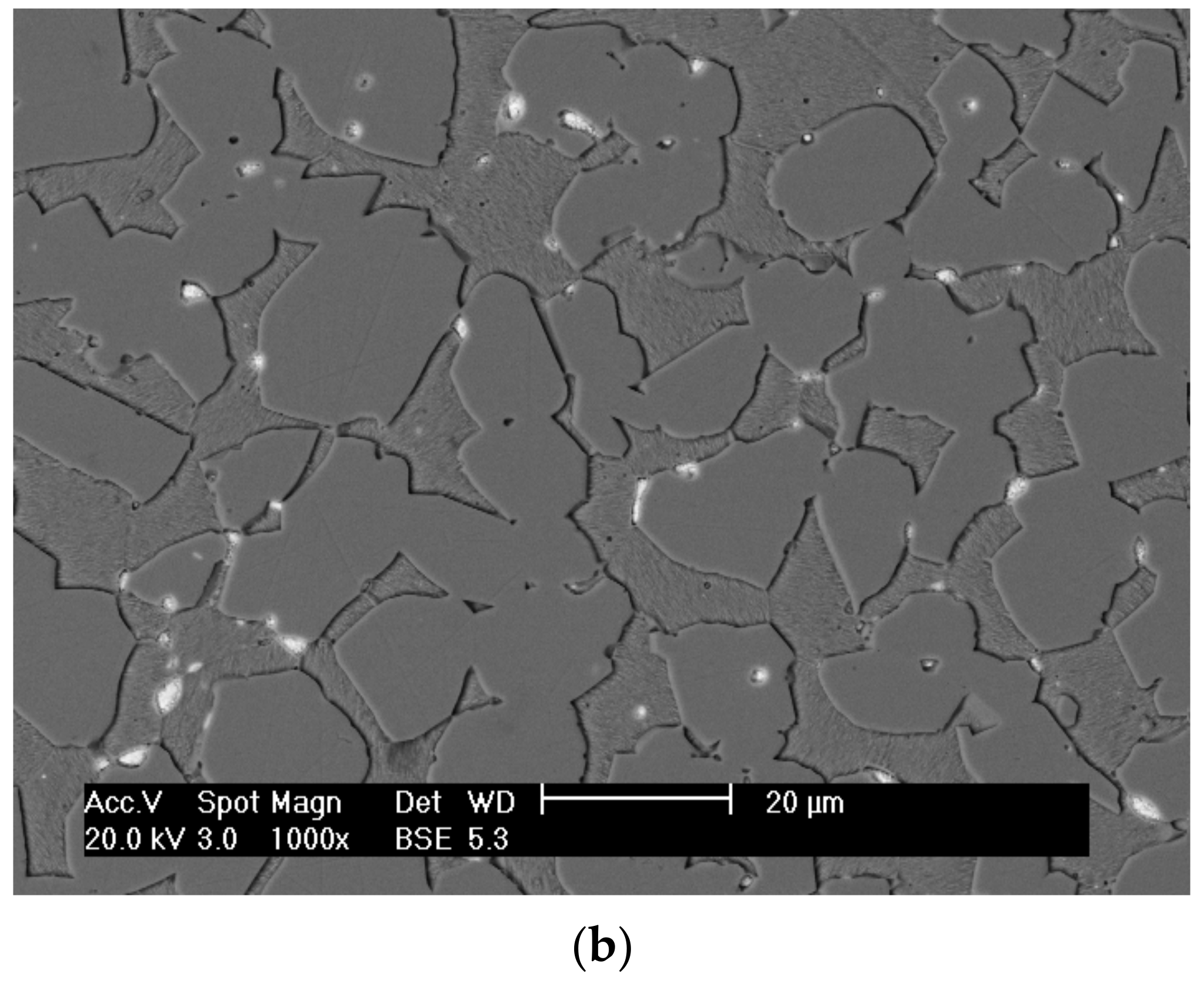
The phase structure of leaded (Pb) brass alloys is governed by a variety of mechanisms. As mentioned previously, Pb addition in conventional brass alloys serves to improve their machinability. Pb preferred accumulation sites are mainly the α/β interphase boundaries (Figure 1). Depending upon the casting and thermomechanical process (TMP) parameters, Pb as a liquid phase during metal forming tends to reduce its surface energy by attaining a spherical shape [27]. To further minimize their interfacial energy. the Pb globules coalesce, forming coarse islands arranged at the α/β interfaces. Pb coalescence increases mean particle size and reduces the Pb particle distribution density, with an adverse effect on machinability [27]. On the contrary, fine and uniform lead distribution enables superior machining behaviour through better chip fracturing and minimises tool wear, while an increased volume fraction of Pb or a non-uniform particle distribution may cause surface cracking during hot working due to hot-shortness [45]. However, hot shortness can also be induced from the excess heat generated in the brass billet from the friction between the brass billet and the container during the extrusion process [25]. As mentioned, the α/β interphase boundaries constitute high interfacial energy sites and thus potential Pb accumulation areas [27,46,47]. When machined, an (α + β)-brass has better chip breaking properties than a pure α-alloy. Further machinability improvements are attained by increasing the length of interphase boundaries, which in turn depends on the β-phase content and the size of the α-phase crystals. Higher β-phase volume fraction and finer α-crystals (for a constant α-phase content) tend to create longer interphase boundaries acting as Pb concentration sites [27,48]. Therefore, lower temperatures would be used during an extrusion process to enable the formation of extended α/β interfaces, an increase in strength and improve the machinability [47,48]. As Pb forms near the end of the solidification process, its particle size and distribution are primarily affected by the casting and solidification conditions, while the phase structure (volume fraction, grain size) is mainly influenced by the extrusion conditions (e.g., temperature, extrusion ratio, speed and cooling rate) [49].

3.1.2. Thermomechanical Processing

The sawing performance of brass bars (CuZn39Pb3) and its relationship to Pb particle size, distribution and the phase structure was reported in a previous study [49]. In this work the presence of β-phase reduced the overall ductility of the alloy and therefore enhanced the segmentation of the machining chips. Holler et al. examined the influence of the extrusion parameters on the phase structure in CuZn40Pb2 [51]. They showed that the percentage of β-phase decreased with an increasing billet temperature and extrusion ratio, while the grain size decreased with decreasing billet temperature and increasing extrusion ratio. Both the grain size and β-phase fraction were less influenced by the extrusion speed. Nevertheless, a study by Loginov et al. concluded that brasses with compositions similar to those mentioned above could benefit greatly from increasing the extrusion temperature to 780–800 °C as the TMP would be taking place entirely within the beta single phase region ensuring better property uniformity [52]. Kunčická et al. further highlighted the importance of maintaining controlled manufacturing processes by studying the failure of CuZn40Pb2 brass fittings from a computational and experimental standpoint. They unveiled that an inhomogeneous temperature profile during the manufacturing process may produce residual stresses in the cooler regions and initiate undesired phase transformations which eventually lead to the manifestation of forming defects [53]. In another case, they investigated a hot-die forged component [53,54]. There, failure originated from a region characterised by plastic flow instability and inhomogeneous stress distribution deeming the area prone to the generation of defects. The cracked region was also characterised by a localised depletion of β phase in favour of the formation of the α phase, thus decreasing the ductility. Sub-micron oxide particles were also present within the crack which were detrimental for the ductility and the cohesive toughness of the material [55].
According to Pantazopoulos and Vazdirvanidis, the beta (β) phase formed in the CuZn39Pb3 alloy may exhibit a characteristic plate-like type morphology possessing different orientations among the various grains [27]. Such morphological characteristics may be considered beneficial for chip-breaking during the machining process. Chandra et al. investigated the intergranular and interphase cavitation in binary alpha/beta brass at 600 °C during superplastic deformation [56]. The process of cavitation was associated with grain boundary sliding. Cavity nucleation occurred at points of stress concentration and such as the sliding interfaces between α–β boundaries rather than on α–α and β–β interfaces [56]. Hentati et al. investigated an incidence of cracking of CuZn39Pb2 during hot forging [57]. The forgeability of the alloy was significantly affected by the work hardening capacity. A decrease in ductility was observed as a result of work hardening and α-phase size reduction during a hot stamping process at 750 °C. Microhardness tests confirmed that stamping increased the brass hardness, while the size of α-phase also decreased. The reduction in α-crystal size and subsequent hardness increase degraded the ductility of the material, causing cracks during the forming process. Such cracks could have been caused from residual stresses generated during TMP. On the other hand, a heat treatment at 300 °C for 1 h had a positive contribution in both tackling the cracking problem and enabling an increase in elongation to fracture up from 22% to 28% [57]. Blaz et al. showed that the reduction in the flow stress during hot deformation of a CuZn39Pb3 alloy resulted from dynamic recovery and dynamic recrystallisation occurring during operation above ~677 °C [58]. Fine Pb particles did not fully inhibit the grain coarsening during dynamic recrystallisation at higher deformation temperatures. During hot deformation above ~727 °C, α → β phase transformation was found to overlap with the structural softening process, resulting in effective grain coarsening followed by effective flow stress reduction. All of the cases presented here further strengthen the fact that attaining a proper microstructure, appropriate mechanical properties and avoid in-process defects or failures heavily depends on the careful control of the TMP.

3.1.3. Mechanical Behaviour

Pantazopoulos and Toulfatzis studied the mechanical behaviour and fracture mechanisms of conventional leaded brasses [59]. A comparison between the CuZn39Pb3 and CuZn36Pb2As brasses showed that the former contained a significantly higher volume fraction of the β-phase than the latter. The beta (β)-phase (CuZn) is an ordered intermetallic phase possessing a body-centred cubic (BCC) crystal structure. This phase is characterised by a higher hardness but less ductility compared to the α-phase which refers to a Cu-based solid solution with the face-centred cubic (FCC) crystal structure. Therefore, the CuZn39Pb3 brass which is a dual phase (α + β) brass containing ~35% β-phase exhibits higher strength, hardness and lower total elongation than the near single α-phase CuZn36Pb2As brass. As expected, the CuZn39Pb3 brass had higher yield strength and tensile strength, but lower elongation compared to the CuZn36Pb2As brass [46]. Upon investigating the side views of the fractured specimens in tension, a ductile fracture mechanism was uncovered in both compositions. The reduction in area was also higher in the CuZn36Pb2As brass compared to CuZn39Pb3, indicating that post-uniform elongation was more pronounced for the CuZn36Pb2As brass [46]. This deviation between the two specimens was attributed to a more extended region of non-uniform elongation in the case of the CuZn36Pb2As brass and was indicative of pronounced post-necking deformation during tensile testing. As the microstructure of the aforementioned specimen consisted primarily of α-phase grains with a uniform distribution of a small percentage of β-phase, it was found to be more resistant to micro-void growth and coalescence under tri-axial stress leading to substantially higher post-uniform elongation and higher reduction of area during necking [59]. Hardness measurements indicated a more homogeneous hardness profile (lower hardness gradient) to CuZn39Pb3 brass compared to the CuZn36Pb2As brass [46]. In this research, the CuZn39Pb3 alloy was characterized by higher hardness values (core ~136 to surface ~149 HV) as compared to CuZn36Pb2As (core ~104 to surface ~136 HV). The topographic features of tensile fracture surfaces of CuZn39Pb3 and CuZn36Pb2As alloys were studied using Scanning Electron Microscopy [59]. In this study, a mixed-mode fracture combining dimple formation and planar faceted fracture induced by a quasi-cleavage process was identified in the case of CuZn39Pb3 alloy. On the other hand, the CuZn36Pb2As alloy exhibited a typical ductile fracture consisting of fine equiaxed dimples. Pantazopoulos investigated the mechanical properties of the CuZn39Pb3 leaded brass [8]. Appreciable ductility was observed prior to fracture through the formation of a localised neck. The subsequent fracture was primarily ductile, and the resulting matched surfaces consisted of interconnected shear cracks. The final metal forming process, cold drawing, led to hardness inhomogeneities due to heterogeneous plastic deformation between the surface and core [8]. Tensile testing at higher temperatures during quasi-static and static loading revealed that the flow stress decreased proportionally to the testing temperature which was expected. The presence of brittle phases (such as β′) together with their morphology is also related to better machinability [60]. Nevertheless, a significant decrease in the ductility between 200 and 400 °C was observed, owing to the partial or complete melting of Pb [46].Moreover, the strain rate sensitivity index increased proportionally to the testing temperature without enabling relevant increases in ductility to take place due to the hot-shortness mechanism [61].
Generally, copper alloys tend to exhibit a reduction in ductility between 300 and 600 °C through a phenomenon called intermediate temperature embrittlement (ITE). This is due to a change in the involved fracture mechanism from transgranular to intergranular fracture as exposure to intermediate temperatures enables grain boundary voiding. Eventually, the ductility of the alloy is restored once the intermediate temperature range is exceeded, enabling dynamic recrystallisation and an operative grain boundary mobility. This effect is enhanced by the presence of alloying elements in the grain boundaries that reduce their structural integrity by encouraging void generation and growth along grain boundaries [62]. In the case of leaded brasses, however, this effect is further amplified due to the synergistic effect of liquid metal embrittlement (LME) where, as previously seen, the partial or complete melting of lead may introduce a liquid phase between crack faces. As such, the local cohesion of the alloy is modified and the kinetics of dynamic embrittlement related to ITE are accelerated as the presence of the liquid phase promotes the rapid diffusion of impurities and void mobility within the grain boundaries [62,63].
The mechanical behaviour of CC763S brass during cyclic loading was investigated by Flegeau et al. under torsional stress. They pinpointed that the fracture mechanism consisted of both ductile and brittle characteristics, with crack growth taking place along α/β grain boundaries where the concentration of intermetallic compounds and pores was the highest. Generally, a higher dislocation density was identified in the interphase α/β boundaries, while α grains remained relatively vacant of dislocations. Subsequently, the interphase boundaries were deemed as the crack nucleation points [64]. In their investigation, Johansson et al. also highlighted the interesting mechanical properties of the CW724R brass compared to the CW614N. The alloy was characterised by Rp0.2 and Rm values of 441.4 MPa and 811.9 MPa, respectively, compared to 254.9 MPa and 561.5 MPa for the high-lead counterpart while retaining similar levels of ductility.

3.2. Eco-Friendly Brasses (Pb-Free)

3.2.1. Novel Lead-Free Brasses

The absence of Pb and potentially other alloying elements directly affects the microstructure of Pb-free brasses. As such, the introduction of soft intermetallic phases that could imitate the effects caused by Pb particles in leaded brasses became a focal research point. The addition of iron (Fe) alongside silicon (Si) was investigated by Johansson et al. [65], attempting to formulate a low-Pb variant of the CW614N brass. Although, the Fe4Si intermetallics were formulated, their intergranular precipitation points did not enable similar effects as in the case of Pb to come into play [65]. Atsumi et al. investigated a high-strength brass (Cu-40% Zn) alloy with magnesium (Mg) fabricated through a powder technology process to uncover the effect of the Mg addition on the microstructural properties of extruded α–β duplex brass alloys [23]. In this work, pre-mixed Cu-40% Zn alloy powder with 0.5–1.5 mass% pure Mg powder (Cu-40% Zn + Mg) was consolidated using spark plasma sintering (SPS). The SPSed Cu-40% Zn + Mg specimens consisted of α–β duplex microstructure containing Mg(Cu1-xZnx)2 intermetallic compounds (IMCs) with a mean particle size of 10–30 μm. Initially, Mg was completely dissolved in the α–β duplex phases through a heat-treatment at 700 °C for 15 min. Thus, to disperse fine IMCs on α–β duplex phase matrix, the SPSed Cu-40% Zn + Mg specimens were pre-heated to achieve a solid solution condition and were afterwards immediately extruded. They studied the tensile properties of the extruded Cu-40% Zn + 1.0% Mg brass and reported an average yield strength (YS) of 328 MPa, ultimate tensile strength (UTS) of 553 MPa and elongation of 25% [66]. The extruded Cu-40% Zn + 1.0% Mg alloy outperformed the conventional binary brass alloy, exhibiting 229 MPa yield strength (YS) and 464 MPa ultimate tensile strength (UTS). The strengthening mechanism of this wrought brass alloy was attributed to the grain refinement due to the pinning effect produced by the fine Mg(Cu1-xZnx)2 precipitates forming at interphase boundaries. The extruded specimen exhibited fine α–β duplex phases containing very fine precipitates of the above Mg(Cu1-xZnx)2 IMCs with 0.5–3.0 μm in diameter [66]. The fracture surfaces of both extruded specimens consisted of fine dimples owing to the evident extremely fine α–β duplex phase structures. The hills and valleys of the extruded Cu-40% Zn fracture surface indicated that the crack paths preferentially followed the primary powder particle interface region. On the other hand, such hills and valleys were never observed in the extruded Cu-40% Zn + 1.5% Mg specimen; however, some fine particles were observed on the fracture surface [66]. Atsumi et al. also investigated the microstructural properties of the Cu-40Zn-0.5Ti ternary alloys having undergone a solid solution treatment [23]. The specimen was pre-heated at 700 °C for 15 min and subsequently extruded consisting of a fine and uniform α–β duplex phase structure with an average grain size of 2.14 μm. Furthermore, fine Ti-based particles with a mean size of 0.5 μm were densely dispersed in the matrix [23]. Atsumi et al. reported that the extruded Cu-40%Zn-0.5 Ti alloy had a mean yield strength of 304 MPa, ultimate tensile strength of 543 MPa and elongation of 44% [23]. Cu-40%Zn-0.5Ti brasses revealed satisfactory strength and good ductility. The high strength of the wrought brass alloy was mainly due to the fine grain size of α and β phases caused by the precipitation of fine Ti-based particles at the grain boundaries [23]. In a previous research Li et al. reported that remarkable grain-refinement and strengthening effects were achieved by the addition of Ti to 60/40 brass through a powder metallurgy process route [67]. However, Ti segregated to the powder particle interface at elevated temperatures, significantly deteriorating the mechanical properties of the BS40–1.0Ti. To inhibit this segregation behaviour of the Ti in the BS40–1.0Ti, the addition of Sn was investigated. Ti was incorporated in the formation of CuSn3Ti5 particles at the grain boundaries, rather than segregating at the powder particle interface, leading to significant grain refinement and enabling strengthening effects on the BS40–0.6Sn1.0Ti brass. These results showed that the introduction of Sn via powder metallurgy to BS40–1.0Ti brass can effectively impede the segregation of Ti and stabilise the mechanical properties at high processing temperatures [67].
An investigation attempting to introduce both Ti and graphite (Gr) to the Cu-40Zn brass showed that the sole addition of Gr to the alloy would yield a better cutting performance alongside a progressive deterioration of the mechanical properties. Nevertheless, the combination of both additives should enable precipitation and dispersion strengthening mechanisms to manifest through the formation of nano Ti clusters and Cu2Ti4O particles, thus maintaining reasonable mechanical properties [68]. The concept of Gr globules incorporation as a microstructural constituent was previously studied by Zhuo et al. through the introduction of cementite (Fe3C) particles in the alloy and a subsequent heat treatment to enable the Fe3C to undergo a graphitisation process [69]. Si has also been extensively investigated as an alloying addition to replace Pb. It acts as a β and β′ phase stabiliser and enables the formation of Widmanstätten-type α phase nucleating from the β interface. Moreover, conducting a solution heat treatment followed by water quenching would further suppress the diffusional nature of the β → β′ transformation, resulting in a martensitic transformation instead. The ease of this process is directly related to the Si content. This concept was explored by Alirezaei and Doostmohammadi and used to design a high-hardness Cu30Zn-Si brass [70]. For the design of novel Pb-free brasses the Zn equivalent rule has been used extensively to predict the formulating phases in said alloys (Equation (1)) [24,71].
X % = 100 % C Z n + C i   · K k   C Z n + C C u + C i   · K k  
where X% is the fictitious zinc equivalent, CZn and CCu the Zn and Cu contents in the specific alloy of interest and ΣCi·Ki the sum of the products of content Ci and the fictitious Zn equivalent Ki of each alloying element. As such, dual phase or single-phase brasses can be designed and compositionally fine-tuned to achieve an ideal combination of properties. Yang et al. used this approach to design an α + β Cu-39Zn-Si-Al brass and manufacture it through low-pressure die casting (LPDC). By altering the processing parameters, they were able to significantly alter the average grain size of the β phase and the morphology of the α phase. Their investigation led to the design of a microstructure consisting of fine β grains and a higher content of rod-like or granular α phase allowing for the manifestation of superior mechanical properties, namely a YS of 359.8 MPa, UTS of 598.9 MPa and an elongation of 15%. Nevertheless, the present composition has not been evaluated in terms of machinability [72]. Expanding upon the concept of Al and Si-containing brasses, D. Suksongram et al. sought to create a high-hardness dual-phase β + γ CuZnSiAlSn brass through the addition of antimony (Sb). According to their research, increasing amounts of Sb up to 1.5 wt.% would enable the inter and intragranular formation of increased amounts of γ phase to the β phase resulting in a significant hardness increase. This could be attributed to an increased solid solution strengthening effect taking place due to the incorporation of Sb within the γ phase. Nonetheless, upon reaching 2.0 wt.% Sb content, a high-Sb intermetallic phase would form, reducing the hardness of the investigated alloying system by roughly 17% [73].
Chandra et al. found that both the ductility as well as the flow stress of α–β brass is significantly affected by the addition of Cerium (Ce) [74]. Ce decreased the solubility of Zn in the α (FCC) phase between 475 °C and 675 °C, consequently shifting the α/(α + β) region of the phase diagram towards lower Zn concentrations. More specifically, the addition of 0.07 wt.% of Ce decreased the α/β ratio from 70:30 to 55:45, improving the ductility and decreasing the flow stress up to a factor of three, at the tested temperature range. Moreover, the hindering effect of Ce addition on Zn solubility indirectly contributed to an expected increase in stacking fault energy (SFE) of the α-phase, improving dislocation mobility. Atsumi et al. investigated the mechanical properties of the high-strength, Pb-free machinable α–β duplex phase Cu–40Zn–Cr–Fe–Sn–Bi alloys [75]. The extruded Cu–40Zn–Cr–Fe–Sn–Bi alloys consisted of α–β phases containing the fine, uniform Cr–Fe IMCs and Bi particles. The average yield strength (YS) and ultimate tensile strength (UTS) of the extruded Cu–40Zn–Cr–Fe–Sn–Bi alloys were 288 MPa and 601 MPa, respectively. These alloys exhibited YS and UTS that were 29% and 40% higher than that of conventional machinable brass Cu–40Zn–Pb alloy. The extruded Cu–40Zn–Cr–Fe–Sn–Bi alloys also maintained 75% of the machinability of the Cu–40Zn–Pb alloy [23]. Fontaine and Keast, compared a lead-free Bi-containing brass (EnviroBrass C89520) to a conventional brass C84400 [5]. In this work, the large difference in grain size was attributed to the dependence of grain growth on alloy chemistry, while the excess concentration of Sn around the particles and at the grain boundaries was due to ‘coring’, a well-documented phenomenon. However, the presence of Sn prevented the segregation of Bi to the grain boundaries and inhibited hot-tearing phenomena during processing involving Bi segregation. It was not clear at this stage how the presence of Sn prevented the segregation of Bi. Either the wetting behaviour of Bi was different in a Cu–Sn alloy than in pure copper or an excess of Sn at the boundaries prevented the segregation of Bi. Scanning transmission electron microscopy (STEM) coupled with electron dispersive X-ray spectroscopy (EDS) did uncover traces of Bi segregation at the boundaries in the brass, even though Bi segregates strongly in pure copper alloys [5]. Further analysis regarding the Bi addition as a possible replacement for Pb was conducted by Thomson et al., who modified the C93700 to replace Pb with Bi. Bi was noted to accomplish a similar role as that of Pb in the present alloying system. Indeed, Bi proved to be a possible replacement, achieving similar mechanical properties as the Pb case. Increased amounts of Bi would be detrimental for the mechanical properties instead. Nevertheless, the morphological characteristics of Bi deem it inferior to Pb by comparison, specifically for bearing applications. The Pb-containing alloy also exhibited greater fatigue resistance compared to the Bi cases. Lastly, tribological testing showed that the Bi-containing compositions induced higher friction forces than those encountered in the Pb-containing alloy. However, the friction forces of the Bi-containing compositions showed less fluctuation compared to that encountered in the Pb-containing alloy [76].
Basori et al. modified the Cu-29Zn brass through the addition of manganese (Mn). The progressive addition of Mn increased the volume fraction of the β-phase in the microstructure as Mn acts as a β-phase stabiliser. Furthermore, the increased Mn content had a minimal effect on twin formation during deformation, while dislocation motion through slip was inhibited due to the pronounced solid solution strengthening effect of Mn [77]. Quan Li et al. showed that the microstructure of the hot extruded Sb-Mg lead-free brass was composed of α, β phases and (Sb, Mg)-containing intermetallic compounds [78]. In this research, the developed Sb-Mg brass was compared to the HPb59-1 brass (CuZn40Pb2) in terms of its mechanical properties and was found to be a suitable replacement, reducing the cost and environment impact of the material. Basori et al. noted that in the Cu-29ZnMn system, the progressive addition of Mn was directly associated with an increase in hardness, Rp0.2 and Rm. An unexpected trend was obtained regarding the maximum elongation of the samples where Mn additions over 3 wt.% would reduce negatively impact ductility. Nevertheless, an addition of up to 3 wt.% Mn had a positive effect instead. This was attributed to the increased β-phase presence at higher Mn contents [77].

3.2.2. Conventional Lead-Free Brasses—Microstructure and Mechanical Properties Optimisation

Toulfatzis et al. studied the fracture behaviour of lead-free brass alloys for machining applications [79]. In this work, the mechanical behaviour under static and dynamic loading of three lead-free brass alloys CuZn42 (CW510L), CuZn38As (CW511L) and CuZn36 (C27450) lead-free brass alloys in comparison to the conventional CuZn39Pb3 (CW614N) leaded brass alloy was studied. The fractographic evaluation was performed on impact tested brass samples to identify the involved fracture mechanisms and their relation to the alloy microstructure. The action of the dimpled fracture mechanism was evident to all the studied alloys; however, the dimple size and distribution exhibited a considerable variation signifying differences in the evolved plastic deformation prior to failure. The largest dimples were detected in the case of CW511L and C27450 alloys, which is consistent with their higher values of impact energy and fracture toughness. In this study, it was also shown that the CuZn42 (CW510L) lead-free brass alloy is a potential candidate in replacing the conventional CuZn39Pb3 (CW614N) leaded brass, combining high tensile strength and tolerable fracture toughness, due to the high presence of the β-phase in the alloy microstructure. The fracture toughness of CW510L and CW511L lead-free alloys, after post-processing heat treatment, was assessed via impact and Crack-Tip-Opening-Displacement (CTOD) testing and presented in Ref. [80]. Moderate improvement in impact energy and CTOD values were obtained for heat treated CW510L brass, showing a salient fracture mode, exhibiting a dominant intergranular crack propagation [80]. Similarly, Kozana et al. manufactured a CuZn39 alloy using various casting techniques. They observed significant differences in the hardness and Rm values of all samples while the only condition altered was the casting mould [81]. G. Iecks et al. carried out investment casting trials on the C35ZA and C30ZA alloys with the addition of aluminium (Al). Due to the segregation of the alloying elements, a finer microstructure was formed with greater hardness compared to other regions of the casting. A thinner cast component exhibited a fine β-phase Widmanstätten structure because of the higher cooling rate. The fineness of Widmanstätten structure is also directly affected by the Al content resulting in variations of hardness [82].
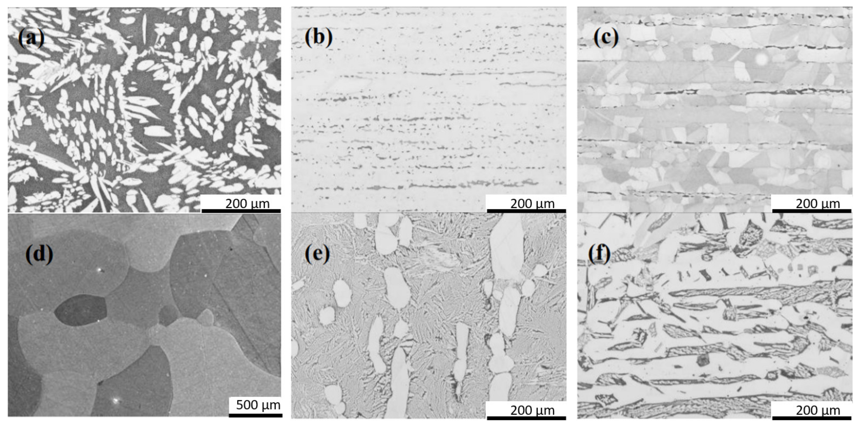
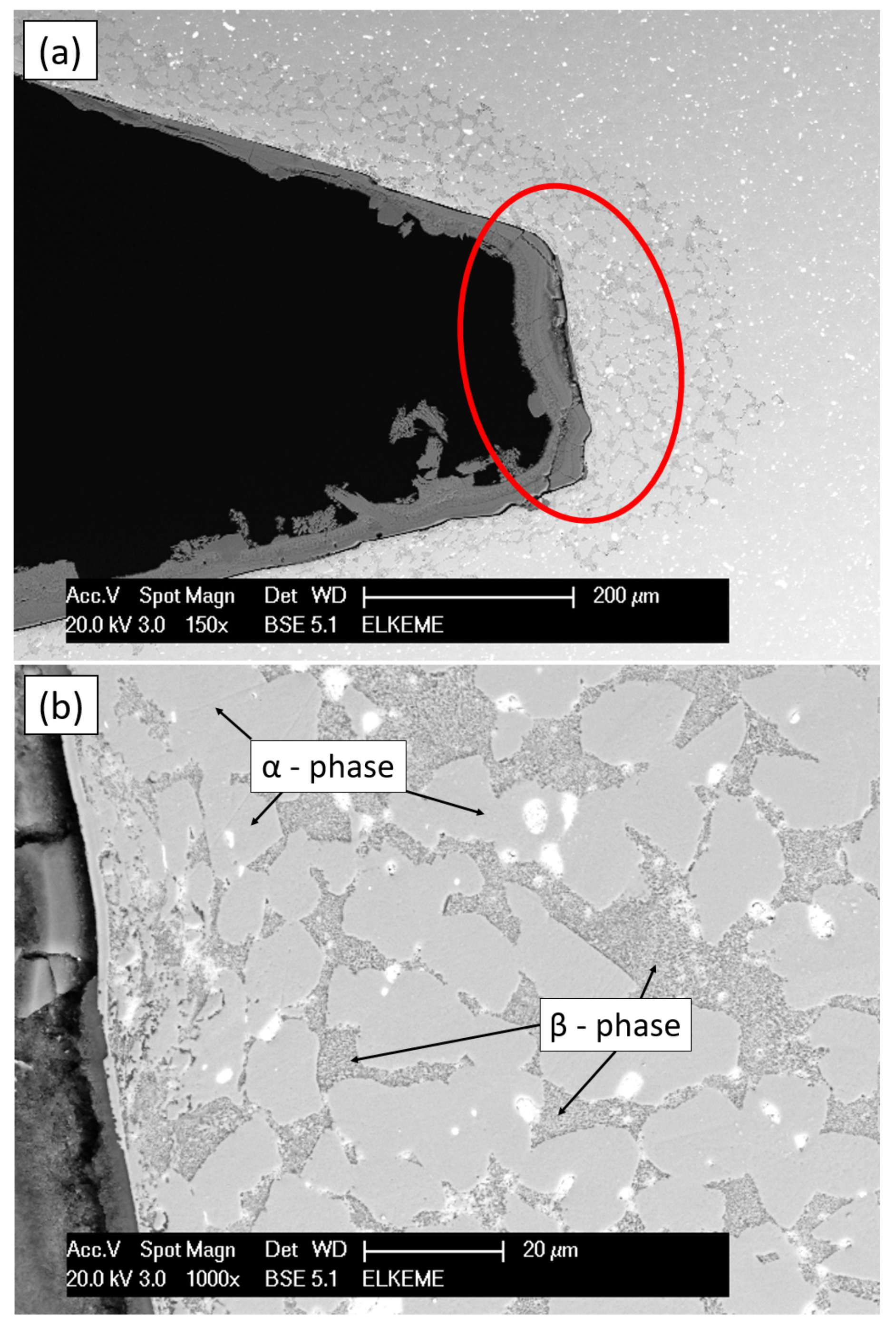
Microstructural evolution studies during severe plastic deformation (SPD) conditions are also important to discern the characteristics and evolution of the phases evident in dual phase brasses throughout the thermomechanical processing of the material [83]. Dhinwal et al. investigated the microstructural changes of a dual phase brass during severe plastic deformation (SPD). The α phase formed mechanical twins with each successive pass resulting in a more random crystallographic texture. The β-phase grains formed an interconnected structure. The overall grain size of the material was also significantly reduced [84]. Kozana et al. attempted to manipulate the microstructural characteristics of the CW511L brass using different casting moulds. Due to the differences between the moulds in terms of the heat transfer coefficients, various microstructures were obtained, the point of variation being the average grain size of the constituent microstructural features [81]. Toulfatzis et al. attempted to modify the microstructure of the CW510L, CW511L and C27450 brasses to improve their machinability by retaining an increased metastable β- phase fraction. This was accomplished by heat treating the alloys at temperatures between 700 and 850 °C for 60–120 min and then immediately subjecting the material to a water quench to suppress the β to α phase transformation. In turn, the increased volume fraction of β phase allowed further strengthening of the alloy at the cost of ductility. Specifically, in the case of the CW510L the amount of β phase present in the microstructure increased from 60% to 100%, whilst reaching 35% and 20% from an initial 5% and 2% for the CW511L and C27450 brasses, respectively, under the ideal heat treatment conditions (Figure 2 and Figure 3, see Ref. [25]). As previously encountered in research investigating similar para-equilibrium conditions, Widmanstätten α-phase was present in the case of CW510L [85].

3.3. Failure Types Encountered in Leaded and Lead-Free Brass Components

As a wider range of brasses becomes integrated into the production line, the matter of component failure and the underlying principles dictating the manifestation of such incidents need to be highlighted. Generally, different types of brasses are more susceptible to different modes of failure owing to their processing route or service life and are extensively analysed in the work by Pantazopoulos [86] and Gupta et al. [87]. However, failure modes that are particularly related to the chemical composition of brasses are further expanded below to provide a potential alloy design direction.

3.3.1. In-Process Failure Modes

The failure of brasses during their thermomechanical processing can be attributed to factors owing mostly to the parameters involved in the casting, extrusion or cold-drawing process [86]. Nevertheless, there are also cases that are dependent exclusively on the alloy composition, with the most prominent one being hot-shortness.

Hot-Shortness

Hot-shortness occurs during the extrusion process in cases where the extrusion temperature is amplified due to the friction between the billet and the container. In turn, this causes SPPs with a low melting point such as Pb particles and regions exhibiting notable chemical segregation to partially melt or become hot short resulting in the possible formation of tears in close proximity to the metal surface [45,86,88]. In cases where novel brass compositions are designed, aiming to replace the Pb particles with a different type of SPPs, this failure mode becomes particularly important. This becomes apparent in cases where Pb has been replaced by Bi. As Bi migrates to the grain boundaries and has a low melting point overheating the brass component can yet again cause hot-shortness [89,90,91,92]. Therefore, a suitable SPP melting point needs to be one of the main points of alloy design to pre-emptively address hot-shortness. This can also be entirely circumvented through the complete elimination of SPPs in cases where the machinability of the brass would not be compromised.

3.3.2. In-Service Failure Modes

Brass components tend to fail during service mostly due to corrosion-related phenomena that are evident in most alloying systems. However, the increased Zn content of brasses can lead to the manifestation of mechanisms almost exclusive to brasses such as dezincification or enhance certain types of corrosion leading to failure such as stress corrosion cracking (SCC) [93,94].

Dezincification

Dezincification may occur during the exposure of brass components to saline and water environments (Figure 4). The mechanism is based upon the selective leaching of Zn due to the electrochemical potential formulating through the interaction between Zn and Cu atoms. This process is facilitated either through the exclusive interaction of Zn with oxygen or chloride ions present in water or through the combined oxidation of both Cu and Zn leading to the eventual establishment of an equilibrium between Cu ions and metallic water and the subsequent deposition of metallic Cu on the brass surface. Therefore, the base material is depleted of Zn leading to the formation a porous Cu-rich layer in the form of red patches on the surface of the material. Dezincification has devastating effects on the mechanical properties of the brass component. This corrosive mechanism can be inhibited from an alloy design perspective through the introduction of tin and arsenic as alloying elements or by controlling the Zn content as this effect is most prominent in brasses containing between 15 and 30 wt.% Zn [86,87].

Stress Corrosion Cracking (SCC)

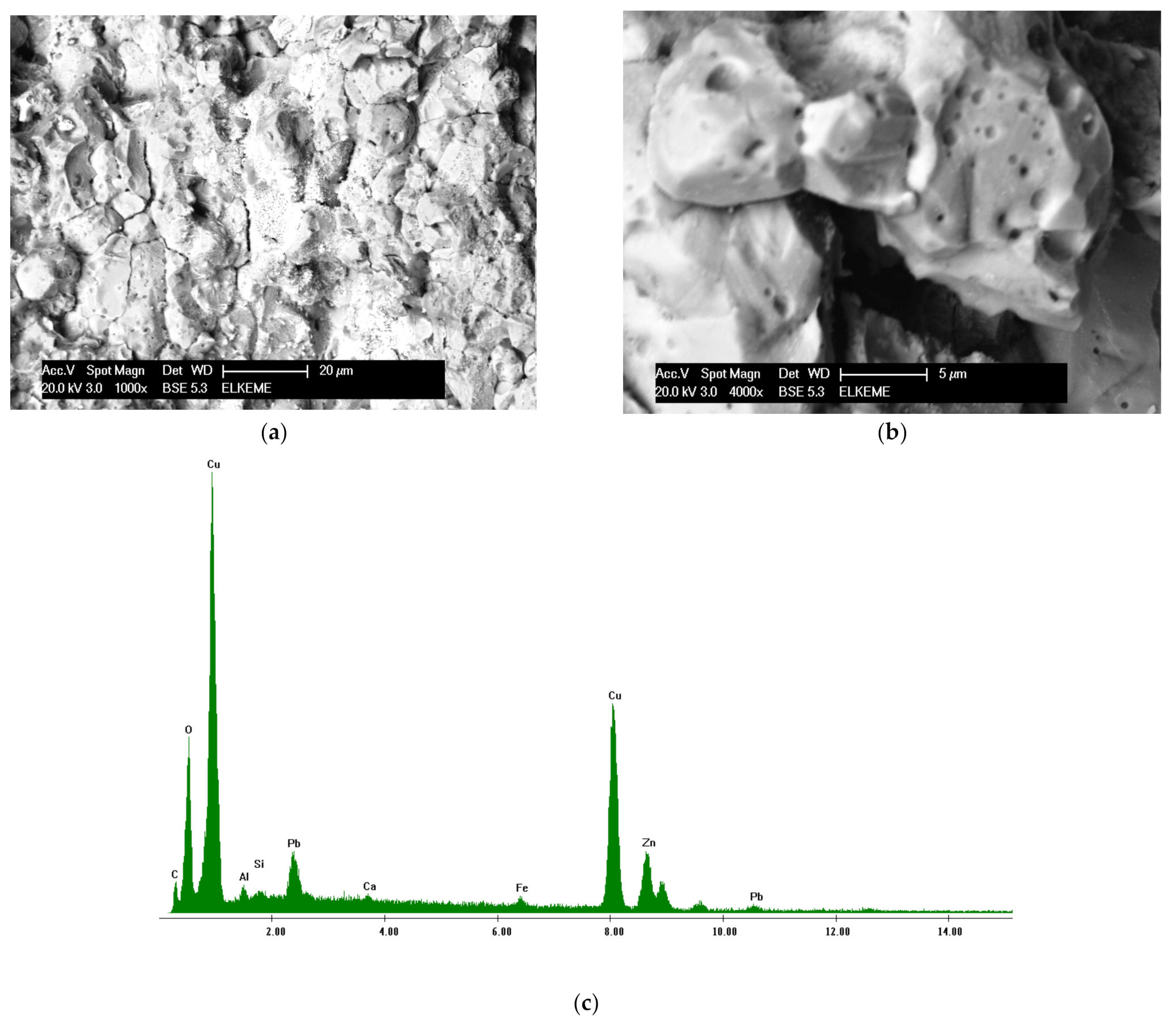
Stress corrosion cracking consists of the formation of intergranular cracks propagating through a metallic material due to the combinatory effect of high residual stresses alongside exposure to a specific corrosive medium and alkalinity. SCC manifests through the selective corrosion of the base material along the more chemically active paths such as interphase and grain boundaries compromising the material integrity in said points. Upon exposure to additional external stresses, cracks form along the compromised regions leading to the formation of additional free surfaces where the corrosion products are deposited and further accelerate the process. SCC occurs mostly in dual-phase brasses with a Zn content around 20–40 wt.%. This failure mode can be avoided by subjecting the component to a low-temperature heat-treatment to erase residual stresses caused by the manufacturing process in the component. In addition, laser shock peening has been proven to improve the SCC resistance of the material by introducing compressive stresses. Furthermore, protective coatings can be employed to further enhance the corrosion resistance of the material. As the Zn content range where this effect occurs is extensive, there are limited alloy design strategies that can be employed as of yet to alleviate SCC in brasses [86,87,95,96]. The fracture caused by SCC usually follows an intergranular path with multiple branching patterns. Typical SCC fracture surfaces and the corresponding EDS spectrum of a machinable brass component are presented in Figure 5 [93].

4. Machinability Evaluation

4.1. Chip Formation and Tool Wear

4.1.1. Leaded Brasses

Toulfatzis et al. investigated the machinability of CuZn39Pb3 and CuZn36Pb2As brasses [46]. In this research, machinability was assessed qualitatively and quantitatively by evaluating the chip size and morphology, and the corresponding cutting tool wear land, employing a single point turning technique according to ISO 3685 [97]. Experimental results indicated that the most critical factors affecting the chip formation quality during brass bar machining were the type of copper alloy used (CuZn39Pb3 and CuZn36Pb2As alloys) and the cutting speed, while it was not found to be sensitive to depth of cut and feed rate variations [46]. It was evident that a significant variety of chip morphology was produced by changing the turning conditions. The single needle, feathery and continuous helical were representative forms that constituted a qualitative indicator of the machining process performance [46]. The formation of shorter chips resulted in better surface finish, lower tool wear and ease of operation, allowing higher cutting speeds, while chip fracturing and removal led to the reduction in tool–chip contact, minimising the risk of built-up edge formation [46].
Gane has shown that the addition of a small quantity of Pb to brass was very effective in reducing friction, both in cutting experiments and in simple sliding-friction experiments [98]. In addition, the ductility of brass was substantially reduced when Pb was present. Both these factors contributed to the considerable improvement in machining properties observed in lead-containing alloys. The reduced friction on the rake face of the tool decreased the specific cutting energy by a factor of about two. As a result, the tool temperature decreased and the tool life improved [98]. As the Pb particles became finer (less than 5 μm) and their distribution more homogeneous, chip-breaking during cutting became more pronounced, and, as a result, machinability improved. Chip fracture in short pieces allows for ease of machining operation; maximum productivity, lower cutting forces, better surface finish of the workpiece, closer tolerances of the final component and less tool wear, thus longer tool life [98]. Preliminary machinability tests were performed by Pantazopoulos in turning operation [8]. The turning speed was up to 395 rpm (the linear speed was up to 0.165 m/s) using a cemented tungsten carbide insert as a cutting tool. The chip size tended to increase by increasing the depth of cut, while no appreciable changes were recorded by changing the feed rate. The depth of cut was constant within the turning cycle (i.e., 0.4, 1.0, or 3.0 mm). The horizontal advancement of the tool per revolution was defined as a function of the feed rate (0.25 or 0.50 mm/rev) [8]. Morphological observations of the produced chips, using optical microscopy, indicated the absence of a flow-zone. Segmented chips with intense shear fractures were produced during turning as a result of the dual phase microstructure (α–β) and the distribution of Pb particles at interphase boundaries. The presence of Pb decreased friction and temperature at the tool–workpiece interface, therefore increasing tool life [8]. Cutting tool wear was principally controlled mainly by the cutting speed and depth of cut used during machining experiments while it appeared to be less sensitive to feed rate or the type of copper alloy variations [46]. Adhesion and sticking of the workpiece debris on the flank face intensified at higher cutting speeds. Moreover, the flank zone revealed several typical wear features, such as abrasive marks and chipping (edge fracturing), of increasing severity as the cutting speed increased (from 2000 to 4000 rpm) [46].
As such, chipping caused the edge fracture of the machining tool, impairing cutting edge sharpness and leading to tool blunting. This type of tool failure increased cutting forces, resulting therefore in further degradation of the machining performance (longer chips, higher fluctuations and chattering, part distortion), causing serious defects on the machined surface quality. Severe damage phenomena such as thermal cracking or flaking were not observed in this study [46]. Toulfatzis et al. determined the optimum cutting conditions using non-parametric design of experiments methods applied in turning processes of leaded brass bars (CuZn39Pb3 and CuZn36Pb2As) for industrial applications [46]. Non-linear fractional factorial designs for the nine-run, three-level, four-factor saturated orthogonal array (L9 = 34) were applied to collect sufficient data to investigate the multi-response optimisation of two main machinability quality characteristics such as the chip morphology and cutting tool wear. The study suggested that concurrent multi-response optimisation gave rise to no specific effect. These optimal settings of the cutting parameters for chip morphology could also be used for cutting tool wear optimization. Confirmation experiments seem to verify the conclusion of this work [46].
Hassan et al. evaluated the influence of cutting parameters such as cutting speed, feed rate and depth of cut in C34000 leaded brass using an analysis of variance (ANOVA) methodology [99]. The purpose of ANOVA was to identify the important parameters for predicting material removal rate. Feed rate was found to be the most significant factor and its contribution to material removal rate was 42.77% within a 95% confidence interval. As such, the feed rate was the most significant factor affecting the material removal rate. The interaction between cutting speed and feed rate was found to be significant with a contribution of 7.75%. The best results for optimal material removal rate were achieved when C34000 leaded brass was machined at a cutting speed of 55 m/min, using a depth of cut of 0.2 mm and a feed rate of 0.35 mm/rev. Johansson et al. investigated brasses with both higher and lower Pb content. It was observed that the machinability of the conventional leaded brass exceeded that of its lower Pb content counterparts by a significant margin. It was however mentioned that the machinability of the CW724R brass was tolerable compared to the original CW614N, while also exhibiting interesting mechanical properties [65]. Thus, the importance of Pb as an addition cannot be overlooked as it directly affects the machinability of the material to a significant extent.

4.1.2. Eco-Friendly Brasses (Pb-Free)

The design criterion for the Pb-free brasses typically concerns the introduction of a soft intermetallic phase uniformly dispersed within the material. Upon contact with the cutting tool, the intermetallic particles should act as a stress concentration point, leading to the segmentation of the formulating chip. Li et al. studied the influence of Ti addition on lead-free brasses [67]. They showed that BS40-2.2Bi alloy exhibited an excellent machinability compared to the Cu40Zn3.2Pb conventional leaded brass. The average drilling time increased with increasing Ti content from 0.3 wt.% to 1.0 wt.%. BS40-2.2Bi with 1.0 wt.% Ti addition could not be penetrated by drilling for more than 180 sec. The different chip morphologies obtained during drilling operations were used to evaluate the machinability of the alloys produced. Compared with the chip shape of the conventional leaded brass (Cu40Zn3.2Pb), BS40-2.2Bi exhibited a different morphology due to the substantial brittleness of Bi affecting the fracture behaviour of the chip and the Ti addition to BS40-2.2Bi, affecting the chip geometry considerably, which transformed into a continuous spiral shape when the Ti content increased to 0.5 wt.% [67].
As the phase diagram indicates, both antimony (Sb) and magnesium can be dissolved partly in copper forming intermetallic compounds with copper [78]. If these intermetallic compounds were dispersedly distributed in the Cu-Zn system, such particles or strips would disturb the metallic matrix continuity and make the chips rupture easily. Thus, the cutting performance of the brass would be improved without the addition of Pb. Additionally, the particles in Sb-Mg brass are not expected to produce stress concentration during forming as they deformed plastically during extrusion, while improving the cutting performance and mechanical properties of the alloy [78].
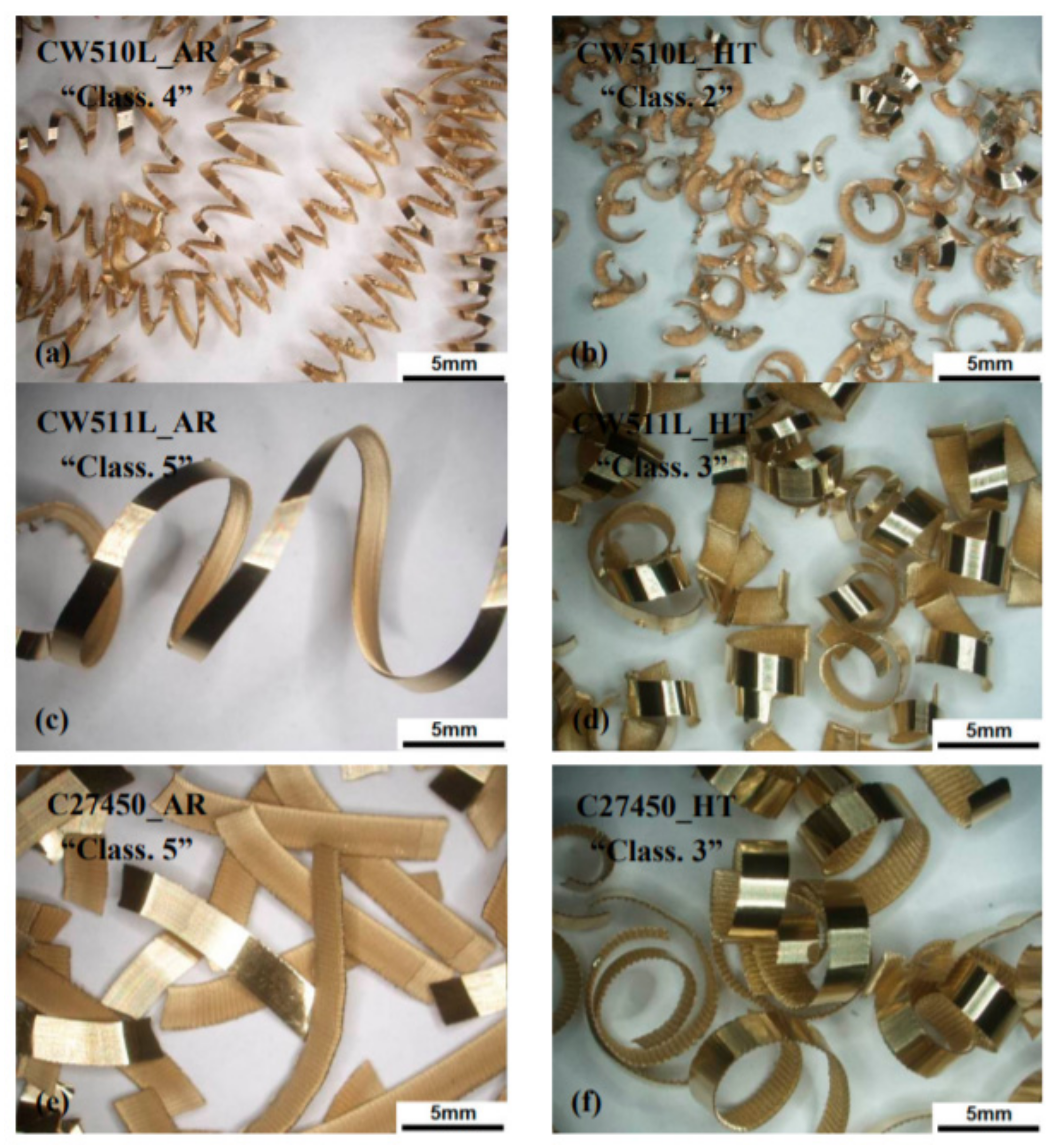
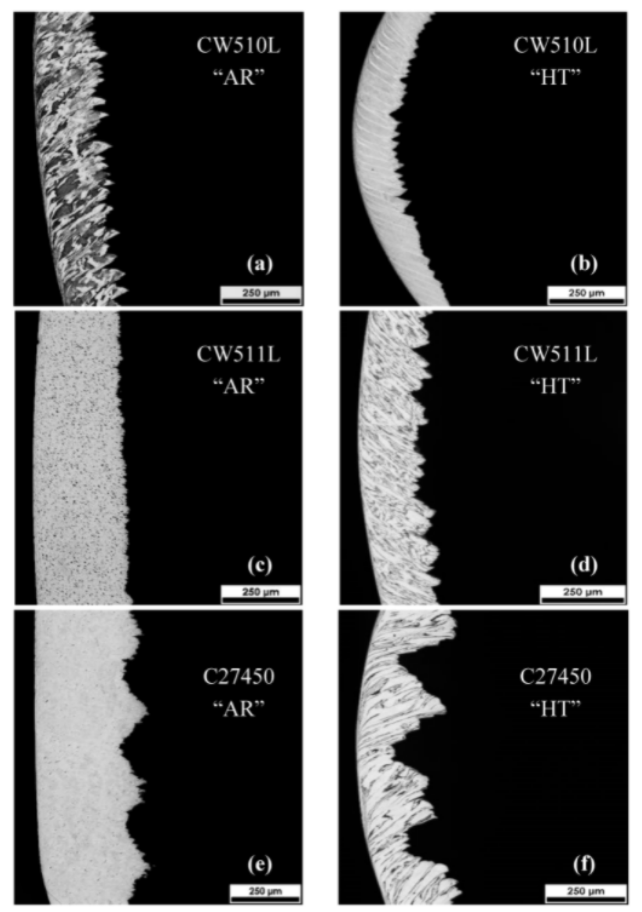
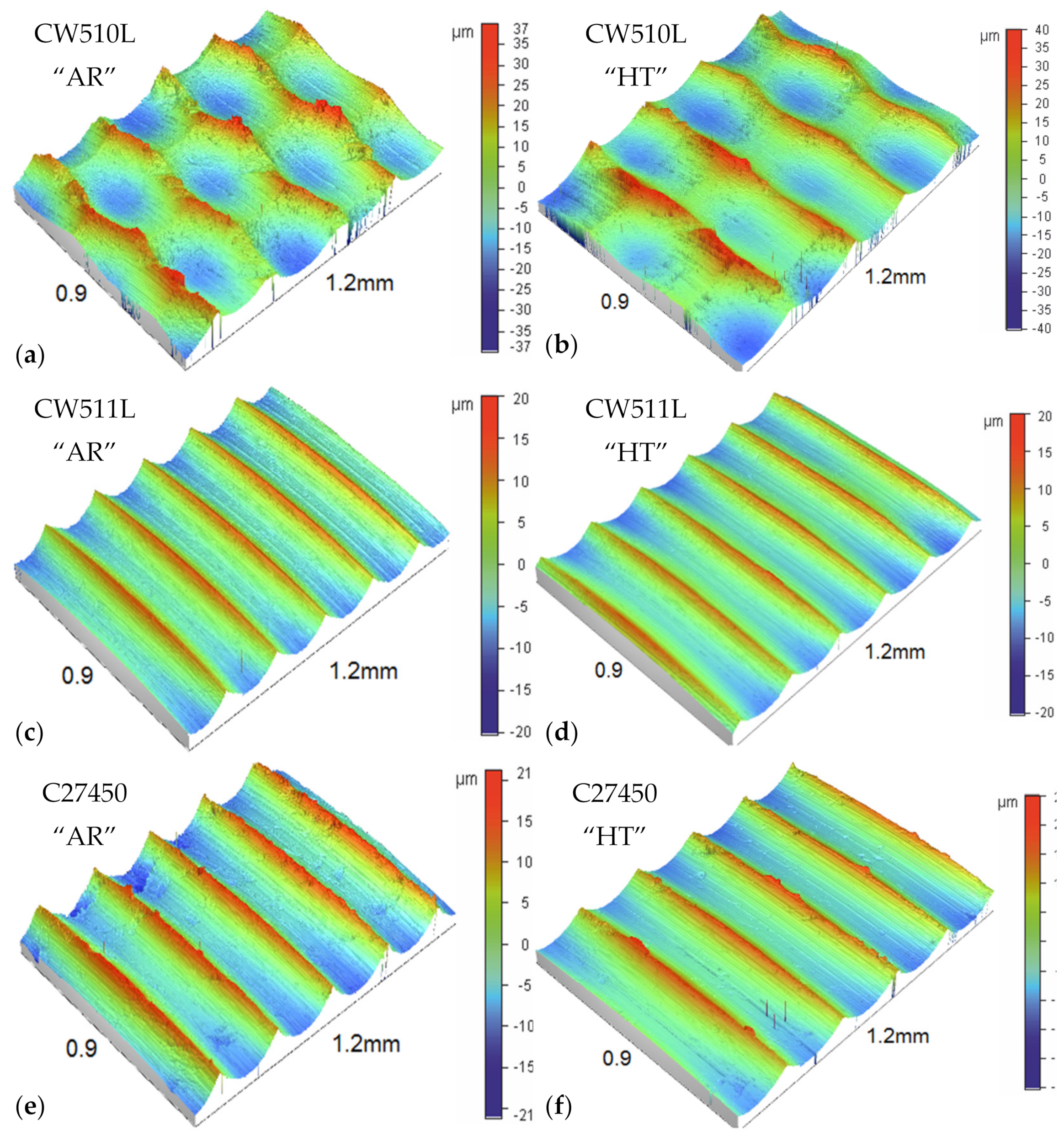
Toulfatzis et al. evaluated the machinability of the CuZn42, CuZn38As and CuZn36 lead-free brasses, comparing them to the conventional leaded CuZn39Pb3 brass [25]. Their results reinforced the perception that an increased volume fraction of β-phase would enable the generation of micro-cracks during the machining process owing to the formation of shear bands. Nevertheless, the chip segmentation process was predominantly controlled by the distribution of Pb particles. Expanding upon this concept, by subjecting the Pb-free alloys to a series of heat treatments (at 775 °C for 60 min for CuZn42 and at 850 °C for 2 h for CuZn38As), a higher volume fraction of β-phase would be stabilised in room temperature as previously discussed. As such, a mild improvement in machinability was to be expected. Indeed, the alloys showed an improvement in machinability relevant to the increased volume fraction of the β-phase and, specifically in the case of the CuZn38As alloy, surpass the conventional leaded counterpart in terms of surface quality [20,21,25,35]. The chip morphologies of the heat-treated lead-free brass alloys compared to the as received ones are depicted in Figure 6 and Figure 7, while the typical characteristic topographic patterns obtained by optical profilometry is presented in Figure 8.
Nobel et al. also studied the machinability of various lead-free alloys, i.e., CW510L, CW511L and CW724R, correlating their machinability to the use of different cutting tool materials [100]. CW724R lead-free silicon brass, in comparison to other lead-free brasses, such as CuZn42 (CW510L) and CuZn38As (CW511L), showed improved machinability concerning chip formation. However, CW724R caused higher tool wear due to the abrasive nature of the Si-rich κ-phase when used alongside a TiAlN-coated carbide tool. In this study the CW510L machining performance using various cutting tools with different coatings (TiAlN, TiB2, DLC, CVD-diamond) was investigated. Adhesive and abrasive wear was reduced by using DLC-coating among the tested PVD-coated tool systems. An additional improvement of cutting performance was achieved using CVD-diamond coating which exhibited exceptional abrasive wear resistance, while adhesion on the rake and flank face was minimised. Polycrystalline diamond tools (PCD) provide another alternative with significant abrasive wear resistance and low adhesion properties. However, the production demand for long tubular chips restricts the use of PCD tools and poses the need for the manufacture of such tools with favourable chip breaking geometry.
Experiments and simulations were implemented by Laakso et al. in order to investigate the effects of different cutting parameters on chip morphology of a low-lead brass [101]. This low-lead brass is not standardised but is compositionally close to the standard CuZn38As (CW511L) lead-free brass. Based on these simulations and experiments it was found that the use of a positive rake angle (+5°), high cutting speed (300 m/min) and low cutting feed rate (0.1 mm/rev) improved chip breakage from a continuous chip to a chip of an average length of 4 mm. High cutting speeds favour chip breakage by increasing chip brittleness due to the suppression of softening effects at high strain rate conditions. Minimisation of cutting force and friction force is achieved by using a positive rake angle (e.g., +5°). Reduction in friction could be realised by decreasing of tool–chip contact area by decreasing feed rate and/or depth of cut. Finite Element Modelling (FEM) simulations agreed with the above results. Furthermore, in a very recent work, the influence of Zn equivalent on the evaluation of chip morphology and machining surface quality of free cutting silicon brasses were investigated by adding Pb replacers (Si and Al elements) [24].
The introduction of additional alloying elements may also enable the stabilisation of various primary phases (i.e., the presence of α, β or γ phases in the Cu-Zn system) at equilibrium. This effect can be expanded further through TMP, directly affecting the fracture behaviour and consequently, the chip-breaking properties and machinability performance of novel compositions [102,103]. Taha et al. showed that, as the Si content increased from 0 wt.% to 1 wt.% in modern lead-free brasses (CuZn40), tool wear slightly increased as well [104]. This was attributed to the decreased volume fractions of the softer phase α and the respective increase in the harder phase β. In Si-containing brass alloys, the detrimental effect of β phase on tool wear has been confirmed. The increase in Si content, from 1 wt.% to 4 wt.% Si, led to a moderate increase in tool wear due to the increased volume fraction of brittle λ, η, and χ intermetallic phases, albeit no significant effects of hardness and microstructure changes were observed. It was also seen that chip formation changed from continuous to discontinuous type with decreasing cutting speed [104]. However, decreasing the cutting speed is recommended as a method to achieve the desirable discontinuous chip type as it results in lower productivity. By adding 4 wt.% Si to the unleaded CuZn40 brass, the chip formation process changed from the undesirable continuous type to an acceptable long bevel and cylindrical long types. It was clearly shown that the chip type was affected by the formation of hard secondary λ-phase precipitates rather than the variation in mechanical properties [104]. Scientific research revealed the benefits of the recycled bismuth–tin (Bi-Sn) solder addition in the lead-free brass alloy Cu-38Zn-0.5Si by reducing the chip-size morphology [105]. The improvement of chip-breaking efficiency was attributed to the presence of the κ-phase in CuZn21Si3P, as opposed to the effect of the α-phase in CuZn38As brass. Likewise, the high percentage of β-phase in the microstructure of CuZn41.5 resulted in the reduction in chip morphology. The influence of the coating type (TiN, TiAlN, TiB2 and DLC on carbide tools) as well as the use of polycrystalline diamond (PCD) tools on chip formation and workpiece quality was analysed for the evaluation of machinability in three low-lead brass alloys (CuZn38As, CuZn42 and CuZn21Si3P). The machining problems were diminished using a diamond-like carbon coating, especially through the reduction in the friction in the secondary shear zone [106]. A machinability comparison between leaded (CuZn39Pb3) and lead-free brass (CuZn21Si3P) alloys was implemented in a relevant work concerning tool wear during machining. Machining of the lead-free brass alloy (CuZn21Si3P) resulted in longer chip size and, eventually, higher tool-wear rates using cemented carbides. The use of coating on carbide tools, e.g., (Ti, V, Zr, Hf, Nb, Ta), was recommended as a possible solution for overcoming excessive tool-wear rates [107,108]. In terms of the chip morphology specifically, high-Si brasses are generally found to produce discontinuous chip types while a lower Si content is associated with better tool interaction and superior surface quality with the added benefit of greater mechanical properties. Nevertheless, the produced chip is of the discontinuous type for the low-Si brasses investigated in the present study [104].

4.2. Cutting Force and Surface Roughness

Vilarinho et al. uncovered several relationships concerning the influence of the chemical composition and the hardness on the different components of cutting forces [109]. The suggested empirical relationships considered both the well-established effect of Pb on the machinability behaviour already shown by several authors and the effect of various alloying elements usually present in brass composition. Conventional alloys (CuZn36Pb3, CuZn39Pb3), with and without additional alloying elements, showed lower values of cutting forces (Fz) than the modern brass alloys of the studied ternary systems, Cu-Sn-Zn, Cu-Al-Zn and Cu-Fe-Zn [109]. However, in some cases conventional alloys exhibited similar or higher values of feed and depth forces in relation to modern brasses. The cutting forces used for machining modern brass alloys of the ternary systems studied in this work were affected by the type and content of each alloying element. Comparing the development of residual stresses on the CuZn21Si3P and CuZn39Pb3 brasses showed the retainment of lower residual stresses in the Si-containing alloy and achieving better abrasion resistance, although higher cutting forces were required. This could also point towards better fatigue and stress-corrosion cracking resistance, but additional investigations are required [110]. When comparing the machinability conventional leaded brasses to their Pb-free counterparts, it becomes apparent that in both cases the depth of cut and feed rate are the most vital parameters influencing the resulting cutting force and surface roughness. The optimisation of said parameters enables the control of both machinability criteria and thus their investigation is of the utmost importance [111]. Scientific research revealed the benefits of the recycled Bi-Sn solder addition in lead-free brass alloy (Cu-38Zn-0.5Si) by reducing the required cutting forces in machining [105]. The influence of the coating type (TiN, TiAlN, TiB2 and DLC on carbide tools), as well as the use of polycrystalline diamond (PCD) tools on machining forces, was analysed to evaluate the machinability in three low-lead brass alloys (CuZn38As, CuZn42, and CuZn21Si3P). The machining problems were diminished using a diamond-like carbon coating, especially through the reduction in the friction in the secondary shear zone [106]. Machining the lead-free brass alloy (CuZn21Si3P) required higher cutting forces using cemented carbides. As such, the use of coating on carbide tools such as (Ti, V, Zr, Hf, Nb, Ta) N was recommended as a possible solution for reducing the cutting forces [107,108].
Concerning the alloys of the Cu–Sn–Zn system, the lowest values of cutting and feed forces were obtained for Sn contents that led to a dual-phase β–γ microstructure. On the other hand, the presence of Al in alloys of the Cu–Al–Zn system had the opposite effect to that of Sn, rising the cutting force as its content increased [109]. In this ternary system, the highest values of cutting force Fz were always obtained for alloys with a β–γ or pure β structures. Regarding Cu–Fe–Zn alloys, no relationship was found between the Fe content and the machinability parameters. Additionally, no significant correlations were made between the cutting forces and the chemical composition when expressed in terms of effective Cu content. However, a minor correlation between the feed force and the effective Cu content on conventional alloys was established, although the authors indicated that further studies would be needed to confirm this behaviour [109].
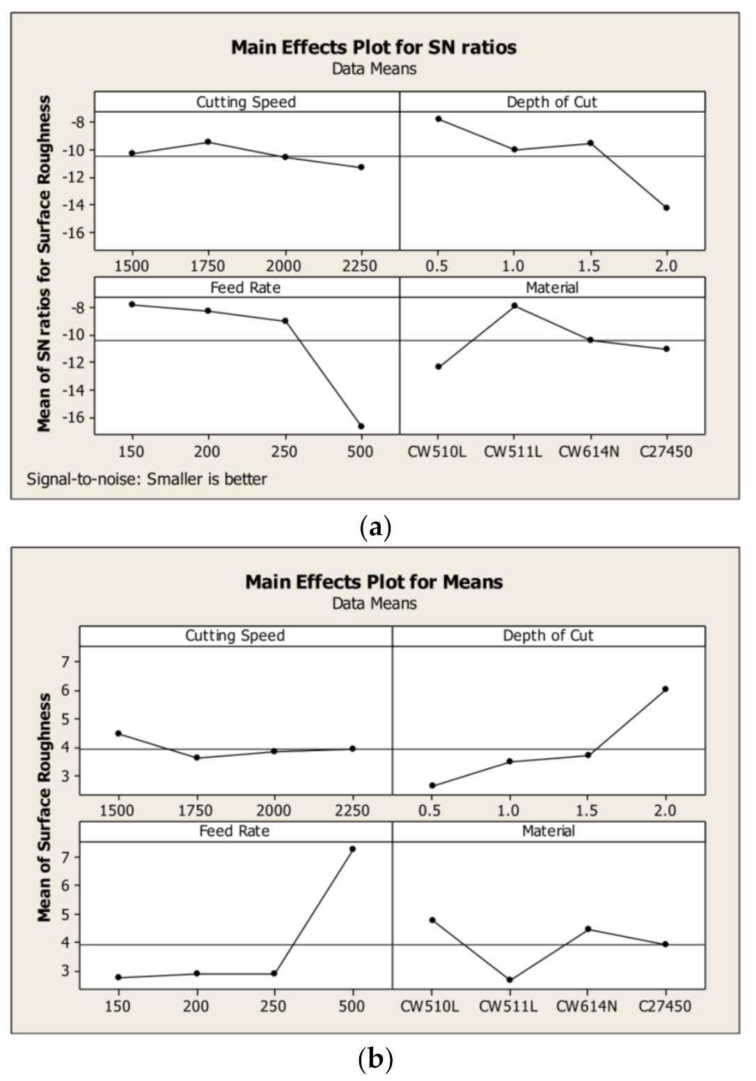
Gaitonde et al. employed Artificial Neural Networks (ANN) to study the effect of cutting speed, feed rate and the required amount of minimum quantity of lubrication (MQL) on two aspects of machinability, namely the specific cutting force and surface roughness in turning of CuZn39Pb3 brass using a K10 carbide tool [112]. In their study, a multilayer feed forward ANN was employed trained by EBPTA (Error-Back Propagation-Training Algorithm). The training patterns required for an input–output database generation were obtained through turning experiments conducted as per Full Factorial Design (FFD). 3D surface plots were generated to analyse the interaction effects of process parameters and the following conclusions were drawn from the present investigation. The minimum specific cutting force existed at high MQL (160–170 mL/h) with medium range of cutting speed (210–220 m/min), Additionally, the specific cutting force was found to be minimal at a higher feed rate (0.20 mm/rev) with a low MQL (100 mL/h). The specific cutting force was highly sensitive to feed rate variations for all values of MQL. The minimum surface roughness resulted in high MQL (160–180 mL/h) with low cutting speed values. Lastly, the surface roughness sharply increased with increasing feed rate irrespective of MQL [94]. They employed the Taguchi method to determine the optimal process parameters for simultaneously minimising the surface roughness and specific cutting force during turning of CuZn39Pb3 brass with a K10 carbide tool [111,112]. In this work, the optimum amount of MQL and the most appropriate cutting speed and feed rate were determined using Analysis of Means (ANOM) and the relative significance of the parameters was identified through ANOVA. The ANOM on multi-response S/N ratio indicated that an optimum MQL of 200 mL/h, cutting speed of 200 m/min and a feed rate of 0.05 mm/rev was necessary to simultaneously minimise surface roughness and specific cutting force. ANOVA illustrated that feed rate was the most dominant parameter followed by MQL and cutting speed in optimising the machinability characteristics. ANOVA also showed that the error contribution was 0.55%, which clearly indicated the absence of the interaction effects of process parameters on optimisation of multiple performance characteristics. Lastly, validation experiments confirmed that the additive model was adequate for determining the optimum quality characteristics at the 95% confidence interval. Utilising ANOVA as means of analysis and optimisation was also explored in the work of Toulfatzis et al. towards the improvement of machinability in CuZn42, CuZn38As and CuZn36 compared to a conventional CuZn39Pb3 brass. To reduce the volume of experiments required for the machinability trials, a DOE Taguchi method in conjunction with ANOVA was used. As such, their statistical analysis converged on the use of a standard L16 orthogonal array. Their work further demonstrated the efficiency of ANOVA in identifying the contributions of individual machining parameters towards the optimisation of the cutting force within 90% accuracy and, to a lesser extent, the surface roughness. Furthermore, the S/N response diagrams showed that the depth of cut would be considered the most significant factor in the machining process which was backed up through ANOVA [50]. Plots of S/N response and data means for cutting force and surface roughness are presented in Figure 9 and Figure 10 [50]. As was confirmed by the ANOVA results, the depth of cut is the most influential factor for cutting force (Pp = 64.3992%) while feed rate is the most influential factor (Pp = 55,3085) for surface roughness, see Table 1 and Table 2 [50].
Taha et al. investigated the machinability based on surface quality and cutting forces in lead-free silicon brass alloys [104]. In this work, the ease of machinability was derived from the machined surface quality. This was evaluated by measuring the machined average surface roughness (Ra) at selected cutting conditions using H20 and H123 tools. Evidently, for all Si-containing brass alloys investigated, Ra was almost independent of depth of cut. Ra increased as the cutting feed increased and gradually decreased as speed increased. Minimum values of Ra were observed for leaded brass, followed by 1 wt.% Si and 2 wt.% Si Alloys, and finally the leaded brass C37700. Even higher Ra values were observed for 3 wt.% Si and 4 wt.% Si alloys [104]. The Ra was found to increase by 40% as the silicon content increased from 1 wt.% to 4 wt.% Si. For all leaded and unleaded alloys, cutting forces were proportional to the depth of cut.
In both cases, the machining behaviour was attributed to increased resistance of chip formation as a result of the increase in the volume of the material removal. The cutting force increased with increasing cutting speed up to a maximum of 50 m/min. This was attributed to the increase in friction on the tool face caused by the chip flow. Further increase in speed led to the decrease in cutting force, which was attributed to the increase in the cutting temperature at high speeds, which in turn resulted in the decrease in the friction forces and shear strength of the material due to thermally induced softening. Moreover, leaded brass exhibited the lowest cutting force value due to the reduction in the coefficient of friction between the chip and the tool face caused by the lubricating effect of Pb. The maximum cutting force was measured for 1% Si and was attributed to the highest alloy strength [104].

4.3. Employment of Vibrational Analysis towards Machinability Evaluation

An emerging trend towards achieving a proper surface finish alongside good economic performance concerns the use of vibrodiagnostics to evaluate the machined components integrity. The term vibrodiagnostics refers to the analysis of the vibrations generated during the machining process. As different materials are characterised by different mechanical and microstructural properties, these variations cause the manifestation of vibrational differences during the cutting process. Specifically, in cases where the workpiece contains for example hard intermetallic phases or inclusions, these irregularities may cause the formation of unwanted vibrations which, in turn can contribute towards an increased oscillation compared to that of a uniform material. Furthermore, tool wear can also be identified through vibrodiagnostics as the geometry of the cutting tool edge is altered during the machining process, generating vibrational differences compared to the initial ones. Thus, by analysing the vibrational characteristics of the cutting process both the workpiece and cutting tool characteristics can be optimised to enable more efficient machinability [113,114,115]. P. Monka et al. applied such methodologies to optimise the cutting parameters for novel milling tools. In this case study, an S-grade sintered carbide with an AlTiN physical vapor deposition (PVD) coating was used to machine a 16MnCr5 steel. Their analysis pointed at the potential for tool optimisation through modifying the tool geometry [116]. In another study, vibrodiagnostics were used to evaluate the tap failure during internal threads machining. Specifically tailored towards tool behaviour prediction, their analysis showed that cutting tool wear was not affected only by the cutting speed but the angle of the tap as well [117]. Similarly, vibrational studies can be used to unveil the tribological characteristics of the newly formed material surfaces [81].

5. Conclusions and Further Research

The development of eco-friendly brass alloys constitutes a critical research field with significant industrial and environmental impact going forward. Brasses are used in a wide range of applications ranging from plumbing fittings to architectural hardware and decorations. This is due to their superior machinability and corrosion resistance compared to most other industrial materials. The machinability of said alloys has been heavily dependent on the incorporation of Pb, which has traditionally been the key to their success. However, as Pb is currently a heavily regulated substance due to environmental and health concerns its substitution is of paramount importance. Through this review we explored the various ways research has progressed relating to the assessment and resolution of the aforementioned challenge. Two primary approaches for solving this problem were evaluated. The design of novel brass compositions and a compositionally invariant route dependent on a series of heat treatments. Compositional modification aims to replicate the beneficial effects of Pb through the incorporation of second phase particles, while the alternative route is intended to stabilise the β-phase. Overall, in terms of mechanical properties, novel compositions were shown to exhibit much improved mechanical properties compared to the conventional ones. The flexibility pertaining to the inclusion of a wide variety of alloying elements enables various strengthening mechanisms to manifest. Similarly, the β-stabilised heat treated Pb-free conventional compositions showed an increase in hardness and strength at the expense of ductility compared to conventional leaded compositions. Regardless, most of the novel compositions were characterised by mediocre machinability compared to conventional leaded brasses, rarely combining both acceptable mechanical properties and machinability. On the contrary, the heat treated conventional Pb-free compositions showed a degree of machinability similar to the leaded compositions, while retaining a good combination of mechanical properties and fracture resistance. It has thus become clear that both approaches are characterised by complementary benefits. As such, we believe that the optimal way towards the next generation of lead-free brasses lies in the development of alloys that can utilise a combination of both aspects of design. Therefore, we recommend the following pathways for further applied research, aiming at the optimisation of the design and processing routes of lead-free copper alloys to surpass the properties and functionality of the conventional leaded brasses satisfying in parallel the requirements of environmental protection, human health and sustainable development:
(a)
The compositional and microstructural design of novel lead-free alloys through computational techniques such as ab initio calculations, CAPHAD (calculation of phase diagrams) approaches alongside general thermodynamic/kinetics and finite element modelling. Such approaches could assess novel compositions in terms of their thermodynamic stability, constituent phases, mechanical properties and corrosion resistance without the expense of physically manufacturing the alloys. Furthermore, these computational approaches could be used alongside experiments to validate and assist in optimization of the thermomechanical processing route of discovered compositions.
(b)
Simultaneous “multi-objective” optimisation of the major quality characteristics (chip morphology, power consumption, cutting force and surface roughness) utilising advanced statistical techniques, such as Desirability Functions (DFs) for the machinability of lead-free brass alloys. The optimisation and validation of the cutting conditions in industrial scale for the fabrication of exemplary final brass industrial component by using complex machining operations (such as CNC machining center).
(c)
Application of on-line monitoring techniques (e.g., vibration sensors/vibrodiagnostics) might be also employed to forecast the cutting tool durability and service lifetime. In addition, the incurred cutting mechanisms could be further predicted and quantified using appropriate numerical simulation by Finite Element Analysis/FEA software.
(d)
Comparative studies concerning the elemental leaching effects between novel lead-free brasses and conventional leaded brasses. This is especially crucial in cases where new alloying additions have been introduced and the resulting alloys have not been investigated in terms of their corrosion performance. This research must be carried out to conduct a risk assessment type study aiming to acknowledge and minimise any impact of these new compositions may have on human health and environment.

Author Contributions

Conceptualization, A.S.P., A.I.T., G.A.P.; methodology, A.I.T. and G.A.P.; literature review A.I.T., G.A.P., P.S.; writing—original draft preparation, A.I.T. and P.S.; writing—review and editing, A.I.T., G.A.P., P.S.; supervision, A.S.P., A.I.T. and G.A.P. All authors have read and agreed to the published version of the manuscript.

Funding

This research received no external funding.

Institutional Review Board Statement

Not applicable.

Informed Consent Statement

Not applicable.

Data Availability Statement

The data supporting the findings of this study are available on request from the corresponding author.

Acknowledgments

The encouragement and support of ELKEME management is highly appreciated.

Conflicts of Interest

The authors declare no conflict of interest.

Appendix A. Chemical Composition of Machinable Brass Alloys

Table A1. Conventional leaded brass compositions.
Conventional Leaded Brasses
Alloy CompositionRef.
CuZn40Pb[4,7]
CuZn39Pb3[8,19,26,27,29,45,46,47,48,49,50,58,59,64,78,82,104,105,106]
CuZn40Pb2[51,52,53,54,55]
CuZn40Pb3[6,7]
CuZn40Pb4[7]
CuZn39Pb2[47,48,57,102]
CuZn36Pb2As[46,50,59]
Table A2. Conventional lead-free (Pb-free) brass compositions.
Conventional Lead-Free Brasses
Alloy CompositionRef.
CuZn42[25,30,79,80,91,104]
CuZn41.5[31]
CuZn40[7,23]
CuZn38[25]
CuZn38As[24,25,31,50,80,81,82,92,93,104]
CuZn38Sn[81]
CuZn37[108]
CuZn36[25,50,79]
CuZn32[64]
CuZn21Si3P[19,30,65,100,106,107,108,109]
Table A3. Novel brass compositions with an increased aluminium (Al) content (alloying elements expressed in wt.%).
Novel Brass Compositions–High Aluminium (Al) Content
CuPbNiFeSnZnAlSiRef.
Bal.----37.63.68-[109]
Bal.2.320.240.330.5332.672.880.06[109]
Bal.--0.028-30.21.66-[82]
Bal.--0.03-33.71.51-[82]
Bal.--0.033-34.21.49-[82]
Bal.--0.032-34.51.48-[82]
Al addition improves corrosion resistance, mechanical properties and in significant amounts can produce a lightweight effect. Al also affects the stability of α/β/γ phases.
Table A4. Novel brass compositions with an increased lead (Pb) content (alloying elements expressed in wt.%).
Novel Brass Compositions–High Lead (Pb) Content
CuPbNiFeSnZnAlSiRef.
Bal.4.230.240.331.0832.281.570.06[109]
Bal.3.5---39.6--[61]
Bal.3.040.020.170.0637.960.02-[3]
Bal.2.9---38.8--[85]
Bal.2.6-0.20.2390.02-[48]
Bal.2.460.250.340.5533.630.8-[109]
Bal.2.430.240.330.5433.152.010.06[109]
Bal.1.650.250.360.5433.750.840.1[109]
Bal.1.46-0.1140.09635.020.503-[33]
Bal.1.45-0.1160.09634.890.506-[33]
Bal.0.95-0.07-38.771.01-[109]
Bal.0.909-0.0950.10439.10.59-[33]
Bal.0.894-0.0950.10438.970.594-[33]
Table A5. Novel brass compositions with an increased tin (Sn) content (alloying elements expressed in wt.%).
Novel Brass Compositions–High Tin (Sn) Content
CuPbFeSnZnRef.
Bal.0.020.0317.3727.49[103]
Bal.0.010.0413.8926.74[103]
Bal.-0.0611.3626.72[103]
Bal.0.020.048.0228.16[103]
Bal.0.020.055.4328.63[103]
Bal.--5.339.33[109]
Bal.--1.0-4.038[21]
Bal.--3.8439.61[109]
Bal.-0.043.1628.57[103]
Bal.--1.7831.53[109]
Bal.--1.3931.9[109]
Bal.-0.031.228.8[102]
Bal.--0.9534.22[109]
Bal.--0.8532.11[109]
Bal.--0.7839.93[109]
Bal.--0.7638.2[109]
Sn addition may promote the formation of β′ enhancing both the machinability and hardness.
Table A6. Novel brass compositions with an increased bismuth (Bi) content (alloying elements expressed in wt.%).
Novel Brass Compositions–High Bismuth (Bi) Content
CuFeSnZnBiSiCrRef.
Bal.0.220.5840.832.85-0.22[75]
Bal.--40.192.20--[17]
Bal.0.230.640.642.02-0.26[75]
Bal.-2382.000.5-[105]
Bal.-1.5381.500.5-[105]
Bal.-1381.000.5-[105]
Bal.0.230.6040.810.99-0.26[75]
Bal.-0.7380.800.5-[105]
Bal.-0.3380.400.5-[105]
Bal.--29.20.27--[77]
Bi addition operates similarly to the Pb addition, improving the machinability through chip segmentation and providing cutting tool lubrication.
Table A7. Novel brass compositions with an increased titanium (Ti) content (alloying elements expressed in wt.%).
Novel Brass Compositions–High Titanium (Ti) Content
CuPbFeSnZnSiTiRef.
Bal.0.020.090.0339.6-1.03[65]
Bal.--0.6540.1-1.03[67]
Bal.---41.2-0.99[67]
Bal.0.160.580.4138.90.130.71[65]
Bal.---39.0-0.50[23]
Ti addition induces CuxTiy type particle precipitation, thus increasing the mechanical properties through precipitation hardening and acting as a grain refiner.
Table A8. Novel brass compositions with an increased silicon (Si) content (alloying elements expressed in wt.%).
Novel Brass Compositions–High Silicon (Si) Content
CuPbNiFeSnZnAlSiRef.
Bal.---1.0434.78-3.68[109]
Bal.----31.913.373.37[109]
Bal.2.270.250.40.5331.770.82.34[109]
Bal.0.01-0.01-31-2.2[73]
Bal.----39.77-1.73[108]
Bal.0.01-0.04-29-1.65[73]
Bal.----35.981.61.6[109]
Bal.----40.55-1.21[109]
Bal.----39.4911.11[24]
Bal.----39.730.71.1[71]
Bal.----38.420.681.1[24]
Bal.----38.441.091.09[109]
Bal.---0.5420.51[73]
Bal.----38.370.340.95[71]
Bal.----39.370.180.95[24]
Bal.0.01-0.04-30-0.93[70]
Bal.----40.430.380.87[71]
Bal.----38.750.90.85[24]
Bal.----40.9-0.83[102]
Bal.----39.130.690.78[24]
Bal.----38.640.510.78[72]
Bal.----36.920.270.78[71]
Bal.----33.680.20.73[71]
Bal.----38.910.50.69[24]
Bal.----39.290.540.54[109]
Bal.----38-0.5[105]
Bal.----37.690.490.49[109]
Bal.----40.67-0.34[102]
Si addition produces fine intermetallic particles, improving machinability and mechanical properties. Si also affects the stability of the α/β/γ phases in brasses.
Table A9. Novel brass composition with an increased content in antimony (Sb), graphite, magnesium (Mg), manganese (Mn), carbon (C) and cerium (Ce) (alloying elements expressed in wt.%).
Novel Brass Compositions–Uncommon Alloying Element Additions
(Sb, Graphite, Mg, Mn, C, Ce)
CuFeSnZnAlSbBiGraphiteSiMgMnCrCCeRef.
Bal.0.095-30.1--0.173---1.26---[77]
Bal.0.063-29.1--0.2---3.48---[77]
Bal.0.096-29.6--0.204---5.83---[77]
Bal.--35-0.0–2.34---0.0–1.79----[22]
Bal.--40---0–1.0-0.3–1.9----[68]
Bal.--40-----1----[59]
Bal.--39.2---0.0–1.0------[1]
Bal.4.78-38--------0.22-[69]
Bal.--38.6---------0.07[74]
Bal.-0.541.60.50.4--1-----[73]
Bal.-0.5410.51--1-----[73]
Bal.-0.540.60.51.4--1-----[73]
Bal.-0.5400.52--1-----[73]
Bal.0.220.5940.86-------0.34--[75]
Sb addition improves machinability by promoting the formation of β′. Produces intermetallic particles which compromise the mechanical properties but further improve machinability. Graphite addition acts similarly to Pb, thus increasing machinability and providing cutting tool lubrication. Mg addition improves machinability by promoting the formation of β′. Produces intermetallic particles which compromise the mechanical properties but further improve machinability. Mn addition promotes the formation of β′ thus increasing the mechanical properties and machinability. C addition operates similarly to graphite, as in the relevant research [68] it was incorporated in the form of Fe3C and underwent a graphitisation process. Ce addition reduces the flow stress of the brass.

References

  1. Imai, H.; Kosaka, Y.; Kojima, A.; Li, S.; Kondoh, K.; Umeda, J.; Atsumi, H. Characteristics and machinability of lead-free P/M Cu60–Zn40 brass alloys dispersed with graphite. Powder Technol. 2010, 198, 417–421. [Google Scholar] [CrossRef]
  2. Chakrabarti, A.K.; Spretnak, J.W. The effect of solute (Zn) concentration on the plastic deformation properties of α and α + β Cu-Zn alloys. Mater. Sci. Eng. 1976, 24, 95–100. [Google Scholar] [CrossRef]
  3. Panagopoulos, C.N.; Georgiou, E.P.; Simeonidis, K. Lubricated wear behavior of leaded α + β brass. Tribol. Int. 2012, 50, 1–5. [Google Scholar] [CrossRef]
  4. Achiţei, D.C.; Minciună, M.G.; Vizureanu, P.; Sandu, A.V.; Cimpoeşu, R.; Istrate, B. Study on structure and properties of CuZnPb alloy. IOP Conf. Ser. Mater. Sci. Eng. 2019, 133, 012015. [Google Scholar] [CrossRef] [Green Version]
  5. La Fontaine, A.; Keast, V.J. Compositional distributions in classical and lead-free brasses. Mater. Charact. 2006, 57, 424–429. [Google Scholar] [CrossRef]
  6. Wolfenden, A.; Wright, P.K. Role of lead in free-machining brass. Met. Technol. 1979, 6, 297–302. [Google Scholar] [CrossRef]
  7. Stoddart, C.T.H.; Lea, C.; Dench, W.A.; Green, P.; Pettit, H.R. Relationship between lead content of Cu-40Zn, machinability, and swarf surface composition determined by auger electron spectroscopy. Met. Technol. 1979, 6, 176–184. [Google Scholar] [CrossRef]
  8. Pantazopoulos, G. Leaded brass rods C 38500 for automatic machining operations: A technical report. J. Mater. Eng. Perform. 2002, 11, 402–407. [Google Scholar] [CrossRef]
  9. Leaded Brasses, Copper Development Association Inc. Available online: https://www.copper.org/resources/properties/microstructure/lead_brasses.html (accessed on 17 January 2022).
  10. Siu, K.W.; Kwok, J.C.M.; Ngan, A.H.W. Thermo-mechanical processing of brass components for potable-water usage increases risks of Pb leaching. Water Res. 2020, 186, 116414. [Google Scholar] [CrossRef]
  11. Korshin, G.V.; Ferguson, J.F.; Lancaster, A.N. Influence of natural organic matter on the corrosion of leaded brass in potable water. Corros. Sci. 2000, 42, 53–66. [Google Scholar] [CrossRef]
  12. Triantafyllidou, S.; Parks, J.; Edwards, M. Lead particles in potable water. Am. Water Work. Assoc. 2007, 99, 107–117. [Google Scholar] [CrossRef]
  13. Tang, M.; Sinsheimer, P.; Sarver, E.; Parks, J.; Edwards, M. Evaluating “lead-free” brass performance in potable water. Corrosion 2019, 75, 865–875. [Google Scholar] [CrossRef]
  14. Elfland, C.; Scardina, P.; Edwards, M. Lead-contaminated water from brass plumbing devices in new buildings. Am. Water Work. Assoc. 2010, 102, 66–76. [Google Scholar] [CrossRef]
  15. Triantafyllidou, S.; Nguyen, C.K.; Zhang, Y.; Edwards, M.A. Lead (Pb) quantification in potable water samples: Implications for regulatory compliance and assessment of human exposure. Environ. Monit. Assess. 2021, 185, 1355–1365. [Google Scholar] [CrossRef]
  16. Estelle, A.A. Drinking water lead regulations: Impact on the brass value chain. Mater. Sci. Technol. 2016, 32, 1763–1770. [Google Scholar] [CrossRef] [Green Version]
  17. Li, S.; Kondoh, K.; Imai, H.; Atsumi, H. Fabrication and properties of lead-free machinable brass with Ti additive by powder metallurgy. Powder Technol. 2011, 205, 242–249. [Google Scholar] [CrossRef]
  18. Available online: https://www.epa.gov/sdwa/use-lead-free-pipes-fittings-fixtures-solder-and-flux-drinking-water (accessed on 12 December 2021).
  19. Schultheiss, F.; Windmark, C.; Sjöstrand, S.; Rasmusson, M.; Ståhl, J.E. Machinability and manufacturing cost in low-lead brass. Int. J. Adv. Manuf. Technol. 2018, 99, 2101–2110. [Google Scholar] [CrossRef] [Green Version]
  20. Kuyucak, S.; Sahoo, M. A review of the machinability of copper-base alloys. Can. Metall. Q. 1996, 35, 1–15. [Google Scholar] [CrossRef]
  21. Suksongkarm, P.; Rojananan, S.; Rojananan, S. Bismuth formation in lead-free Cu-Zn-Si yellow brass with various bismuth-tin alloy additions. Mater. Trans. 2018, 59, 1747–1752. [Google Scholar] [CrossRef] [Green Version]
  22. Adineh, M.; Doostmohammadi, H. Microstructure, mechanical properties and machinability of Cu-Zn-Mg and Cu-Zn-Sb brass alloys. Mater. Sci. Technol. 2019, 35, 1504–1514. [Google Scholar] [CrossRef]
  23. Atsumi, H.; Imai, H.; Li, S.; Kondoh, K.; Kousaka, Y.; Kojima, A. The effect of solid solutionizing Ti element on microstructural and mechanical properties of extruded Cu-40Zn-Ti ternary alloy. Trans. JWRI 2011, 40, 67–71. [Google Scholar]
  24. Yang, C.; Ding, Z.; Tao, Q.C.; Liang, L.; Ding, Y.F.; Zhang, W.W.; Zhu, Q.L. High-strength and free-cutting silicon brasses designed via the zinc equivalent rule. Mater. Sci. Eng. A 2018, 723, 296–305. [Google Scholar] [CrossRef]
  25. Toulfatzis, A.; Pantazopoulos, G.; David, C.; Sagris, S.; Paipetis, A. Final heat treatment as a possible solution for the improvement of machinability of Pb-free brass alloys. Metals 2018, 8, 575. [Google Scholar] [CrossRef] [Green Version]
  26. Toulfatzis, A.I.; Pantazopoulos, G.A.; Paipetis, A.S. Microstructure and properties of lead-free brasses using post-processing heat treatment cycles. Mater. Sci. Technol. 2016, 32, 1771–1781. [Google Scholar] [CrossRef]
  27. Pantazopoulos, G.; Vazdirvanidis, A. Characterization of the microstructural aspects of machinable α–β phase brass. Microsc. Anal. 2008, 22, 13–16. [Google Scholar]
  28. Vaxevanidis, N.M.; Fountas, N.A.; Koutsomichalis, A.; Kechagias, J.D. Experimental investigation of machinability parameters in turning of CuZn39Pb3 brass alloy. Procedia Struct. Integr. 2018, 10, 333–341. [Google Scholar] [CrossRef]
  29. Zoghipour, N.; Tascioglou, E.; Atay, G.; Kaynak, Y. Machining-induced surface integrity of holes drilled in lead-free brass alloy. Procedia CIRP 2020, 87, 148–152. [Google Scholar] [CrossRef]
  30. Nobel, C.; Hofmann, U.; Klocke, F.; Veselovac, D.; Puls, H. Application of a new, severe-condition friction test method to understand the machining characteristics of Cu-Zn alloys using coated cutting tools. Wear 2015, 344, 58–68. [Google Scholar] [CrossRef]
  31. Naik, D.B.; Dave, A.K. Multipass, multicriterion optimization in turning. Int. J. Adv. Manuf. Technol. 1998, 14, 544–548. [Google Scholar] [CrossRef]
  32. Besseris, G.J. Non-linear nonparametric quality screening in low sampling testing. Int. J. Qual. Reliab. Manag. 2010, 27, 893–915. [Google Scholar] [CrossRef]
  33. Amaral, L.; Quinta, R.; Silva, T.E.; Soares, R.M.B.; Castellanos, S.D.; De Jesus, A.M.P. Effect of lead on the machinability of brass alloys using polycrystalline diamond cutting tools. J. Strain Anal. 2018, 53, 602–615. [Google Scholar] [CrossRef]
  34. Vaxevanidis, N.M.; Kechagias, J.D.; Fountas, N.A.; Manolakos, D.E. Evaluation of machinability in turning of engineering alloys by applying artificial neural networks. Open Constr. Build. Technol. J. 2014, 8, 389–399. [Google Scholar] [CrossRef] [Green Version]
  35. Abbas, A.; Pimenov, D.; Erdakov, I.; Taha, M.; El Rayes, M.; Soliman, M. Artificial intelligence monitoring of hardening methods and cutting conditions and their effects on surface roughness, performance, and finish turning costs of solid-state recycled aluminum alloy 6061 chips. Metals 2018, 8, 394. [Google Scholar] [CrossRef] [Green Version]
  36. Hrechuk, A.; Bushlya, V.; M’Saoubi, R.; Ståhl, J.-E. Quantitative analysis of chip segmentation in machining using an automated image processing method. Procedia CIRP 2019, 82, 314–319. [Google Scholar] [CrossRef]
  37. Besseris, G.J. A methodology for product reliability enhancement via saturated-unreplicated fractional factorial designs. Reliab. Eng. Syst. Saf. 2010, 95, 742–749. [Google Scholar] [CrossRef]
  38. Fountas, N.; Koutsomichalis, A.; Kechagias, J.D.; Vaxevanidis, N.M. Multi-response optimization of CuZn39Pb3 brass alloy turning by implementing Grey Wolf algorithm. Frat. Ed Integrità Strutt. 2019, 50, 584–594. [Google Scholar] [CrossRef] [Green Version]
  39. Arvidssson, M.; Gremyr, I. Principles of robust design methodology. Qual. Reliab. Eng. Int. 2008, 24, 23–35. [Google Scholar] [CrossRef]
  40. Manna, A.; Bhattacharyya, B. Taguchi and Gauss elimination method: A dual response approach for parametric optimization of CNC wire cut EDM of PRAlSiCMMC. Int. J. Adv. Manuf. Technol. 2006, 28, 67–75. [Google Scholar] [CrossRef]
  41. Ilzarbe, L.; Álvarez, M.J.; Viles, E.; Tanco, M. Practical applications of design of experiments in the field of engineering: A bibliographical review. Qual. Reliab. Eng. Int. 2008, 24, 417–428. [Google Scholar] [CrossRef]
  42. Viles, E.; Tanco, M.; Ilzarbe, L.; Alvarez, M.J. Planning experiments, the first real task in reaching a goal. Qual. Eng. 2009, 21, 44–51. [Google Scholar] [CrossRef]
  43. Tanco, M.; Viles, E.; Ilzarbe, L.; Alvarez, M.J. Barriers faced by engineers when applying design of experiments. TQM J. 2009, 21, 565–575. [Google Scholar] [CrossRef]
  44. Tanco, M.; Viles, E.; Ilzarbe, L.; Alvarez, M.J. Implementation of design of experiments projects in industry. Appl. Stoch. Models Bus. Ind. 2009, 25, 478–505. [Google Scholar] [CrossRef]
  45. Pantazopoulos, G.; Vazdirvanidis, A. Failure analysis of a fractured leaded-brass (CuZn39Pb3) extruded hexagonal rod. J. Fail. Anal. Prev. 2008, 8, 218–222. [Google Scholar] [CrossRef]
  46. Toulfatzis, A.I.; Besseris, G.J.; Pantazopoulos, G.A.; Stergiou, C. Characterization and comparative machinability investigation of extruded and drawn copper alloys using non-parametric multi-response optimization and orthogonal arrays. Int. J. Adv. Manuf. Technol. 2011, 57, 811–826. [Google Scholar] [CrossRef]
  47. Mapelli, C.; Venturini, R. Dependence of the mechanical properties of an α/β brass on the microstructural features induced by hot extrusion. Scr. Mater. 2006, 54, 1169–1173. [Google Scholar] [CrossRef]
  48. Momeni, A.; Ebrahimi, G.R.; Faridi, H.R. Effect of chemical composition and processing variables on the hot flow behavior of leaded brass alloys. Mater. Sci. Eng. A 2015, 626, 1–8. [Google Scholar] [CrossRef]
  49. Garcia, P.; Rivera, S.; Palacios, M.; Belzunce, J. Comparative study of the parameters influencing the machinability of leaded brasses. Eng. Fail. Anal. 2010, 17, 771–776. [Google Scholar] [CrossRef]
  50. Toulfatzis, A.I.; Pantazopoulos, G.A.; David, C.N.; Sagris, D.S.; Paipetis, A.S. Machinability of eco-friendly lead-free brass alloys: Cutting-force and surface-roughness optimization. Metals 2018, 8, 250. [Google Scholar] [CrossRef] [Green Version]
  51. Holler, K.; Reetz, B.; Müller, K.B.; Pyzalla, A.; Reimers, W. Microstructure and properties of hot extruded brass CuZn40Pb2. Mater. Sci. Forum 2003, 426–432, 3667–3672. [Google Scholar] [CrossRef]
  52. Loginov, Y.N.; Ovchinnikov, S. Increase in the uniformity of structure and properties of extruded workpieces of alpha + beta lead brasses. Metallurgist 2015, 8, 342–347. [Google Scholar] [CrossRef]
  53. Kunčická, L.; Jambor, M.; Weiser, A.; Dvořák, J. Structural factors inducing cracking of brass fittings. Materials 2021, 14, 3255. [Google Scholar] [CrossRef] [PubMed]
  54. Kunčická, L.; Benč, M.; Andreyachshenko, V. Effect of residual stress on cracking of hot-die forged brass fittings. IOP Conf. Ser. Mater. Sci. Eng. 2021, 1190, 012031. [Google Scholar] [CrossRef]
  55. Kunčická, L.; Kocich, R. Effects of temperature (in)homogeneity during hot stamping on deformation behavior, structure and properties of brass valves. Adv. Res. Mater. 2021, 202101414. [Google Scholar] [CrossRef]
  56. Chandra, T.; Jonas, J.J.; Taplin, D.M.R. Grain-boundary sliding and intergranular cavitation during superplastic deformation of α/β brass. J. Mater. Sci. 1978, 13, 2380–2384. [Google Scholar] [CrossRef]
  57. Hentati, N.; Makni, A.; Elleuch, R. Study of failure modes affecting a crimped nut related to forging process. J. Fail. Anal. Prev. 2012, 12, 130–138. [Google Scholar] [CrossRef]
  58. Blaz, L.; Konior, Z.; Majda, T. Structural aspects of α/β transformation in hot deformed CuZn-39Pb3 alloy. J. Mater. Sci. 2001, 36, 3629–3635. [Google Scholar] [CrossRef]
  59. Pantazopoulos, G.A.; Toulfatzis, A.I. Fracture modes and mechanical characteristics of machinable brass rods. Metallogr. Microstruct. Anal. 2012, 1, 106–114. [Google Scholar] [CrossRef] [Green Version]
  60. Adineh, M.; Doostmohammadi, H.; Raiszadeh, R. Effect of Si and Al on the microstructure, mechanical properties and machinability of 65Cu-35Zn brass. Iran. J. Mater. Sci. Eng. 2019, 16, 21–32. [Google Scholar]
  61. Kashyap, B.P.; Verma, S.; Mandlik, P.; Kumar, N.; Toppo, S.P. Effect of test temperature on tensile properties of α/β brass containing lead. Mater. Sci. Technol. 2006, 22, 363–367. [Google Scholar] [CrossRef]
  62. Laporte, V.; Mortensen, A. Intermediate temperature embrittlement of copper alloys. Int. Mater. Rev. 2009, 54, 94–116. [Google Scholar] [CrossRef] [Green Version]
  63. Wolley, D.J.; Fox, A.G. The embrittlement of leaded and unleaded α+β (60-40) brasses in the temperature range 300 to 500 °C. J. Mater. Sci. Lett. 1988, 7, 763–765. [Google Scholar] [CrossRef]
  64. Flegeau, G.; Taleb, L.; Hauet, A.; Vassal, C. Cyclic behavior of an industrial brass Cu Zn32. In Key Engineering Materials; Trans Tech Publications Ltd.: Bäch, Switzerland, 2013; Volume 535, pp. 189–192. [Google Scholar]
  65. Johansson, J.; Persson, H.; Ståhl, J.-E.; Zhou, J.-E.; Bushlya, V.; Schultheiss, F. Machinability evaluation of low-lead brass alloys. Procedia Manuf. 2019, 38, 1723–1730. [Google Scholar] [CrossRef]
  66. Atsumi, H.; Imai, H.; Li, S.; Kondoh, K.; Kousaka, Y.; Kojima, A. Fabrication and properties of high-strength extruded brass using elemental mixture of Cu-40% Zn alloy powder and Mg particle. Mater. Chem. Phys. 2012, 135, 554–562. [Google Scholar] [CrossRef]
  67. Li, S.; Imai, H.; Atsumi, H.; Kondoh, K.; Kojima, A.; Kousaka, Y.; Yamamoto, K.; Takahashi, M. The effects of Ti and Sn alloying elements on precipitation strengthened Cu40Zn brass using powder metallurgy and hot extrusion. Mater. Sci. Eng. A 2012, 535, 22–31. [Google Scholar] [CrossRef] [Green Version]
  68. Zhang, X.; Ma, C.; Li, S.; Pan, D.; Zhen, F. Interface design of lead-free free-cutting titanium reinforced graphite brass composites and its effect on mechanical properties and cutting performance. Mater. Sci. Eng. A 2020, 774, 138909. [Google Scholar] [CrossRef]
  69. Zhuo, H.-O.; Tank, J.-C.; Xue, Y.-Y.; Ye, N. Preparation of lead-free free-cutting graphite brasses by graphitization of cementite. Trans. Nonferrous Met. Soc. China 2015, 25, 3252–3257. [Google Scholar] [CrossRef]
  70. Alirezaei, M.; Doostmohammadi, H. Microstructure evolution in cast and equilibrium heat-treated CuZn30-(Si) alloys. Int. J. Cast Met. Res. 2016, 29, 222–227. [Google Scholar] [CrossRef]
  71. Yang, C.; Yang, Y.; Lin, G. Tailoring chip morphology by correlating the microstructure and dynamic yield strength in turning of lead-free silicon brasses. J. Manuf. Processes 2020, 53, 420–430. [Google Scholar] [CrossRef]
  72. Yang, C.; Ye, W.; Yang, Y.; Wang, F.; Ding, Y.; Zhu, Q.; Zhang, W. Microstructural evolution and mechanical behavior of lead-free silicon brass manufactured by low-pressure die casting. J. Mater. Eng. Perform. 2018, 27, 5478–5488. [Google Scholar] [CrossRef]
  73. Suksongkarm, D.; Rojananan, S.; Rojananan, S. Microstructure and hardness of Cu-Zn-Si-Al-Sn with antimony addition. Adv. Mater. Res. 2013, 802, 179–183. [Google Scholar] [CrossRef]
  74. Chandra, T.; Jonas, J.J.; Taplin, D.M.R. The mechanical behavior of cerium-modified alpha-beta brass at high temperatures. J. Mater. Sci. 1976, 11, 1843–1848. [Google Scholar] [CrossRef]
  75. Atsumi, H.; Imai, H.; Li, S.; Kondoh, K.; Kousaka, Y.; Kojima, A. High-strength, lead-free machinable α–β duplex phase brass Cu–40Zn–Cr–Fe–Sn–Bi alloys. Mater. Sci. Eng. A 2011, 529, 275–281. [Google Scholar] [CrossRef]
  76. Thomson, J.; Zavadil, R.; Sahoo, M. Development of a lead-free bearing material for aerospace applications. Int. J. Met. 2010, 4, 19–30. [Google Scholar] [CrossRef]
  77. Basori, I.; Pratiwi, H.I.; Sofyan, B.T. Effects of manganese on the microstructures, mechanical properties and deformation characteristics of Cu-29Zn alloy. Mater. Sci. Forum 2017, 917, 212–217. [Google Scholar] [CrossRef]
  78. Li, Z.Q.; WeiDong, W.; KaiZhou, L.; GengChun, C.; WeiPing, C. Study on microstructure and properties of brass containing Sb and Mg. Sci. China Ser. E Technol. Sci. 2009, 52, 2172–2174. [Google Scholar]
  79. Toulfatzis, A.I.; Pantazopoulos, G.A.; Paipetis, A.S. Fracture behavior and characterization of lead-free brass alloys for machining applications. J. Mater. Eng. Perform. 2014, 23, 3193–3206. [Google Scholar] [CrossRef]
  80. Toulfatzis, A.I.; Pantazopoulos, G.A.; Paipetis, A.S. Fracture mechanics properties and failure mechanisms of environmental-friendly brass alloys under impact, cyclic and monotonic loading conditions. Eng. Fail. Anal. 2018, 90, 497–517. [Google Scholar] [CrossRef]
  81. Kozana, J.; Garbacz-Klempka, A.; Piękoś, M. Lead-free casting brasses. Investigations of the corrosion resistance and shaping of microstructure and properties. Arch. Foundry Eng. 2019, 19, 113–118. [Google Scholar]
  82. Iecks, G.; Maiolo, L.M.A.; Bortolozo, A.D.; Osório, W.R. Designing a microstructural array associated with hardness of dual-phase Cu-Zn alloy using investment casting. Mater. Res. 2018, 21, e20171059. [Google Scholar] [CrossRef]
  83. Lobanov, M.L.; Danilov, S.V.; Pastukhov, V.I. Crystallographic peculiarities of β-α transformation in brass induced by hot extrusion. Solid State Phenom. 2019, 299, 541–545. [Google Scholar] [CrossRef]
  84. Dhinwal, S.S.; Shukla, A.J.; Biswas, S.; Chouhan, D.K. Evolution of microstructure and crystallographic texture in α–β brass during equal channel angular pressing. Mater. Characteris. 2020, 163, 110270. [Google Scholar] [CrossRef]
  85. Ibrahim, A.; Rizal, S.; Ali, N.; Huzni, S. The effect of chemical composition on grain size and formability of the free-lead Cu-30Zn alloy: A short review. IOP Conf. Ser. Mater. Sci. Eng. 2019, 536, 012019. [Google Scholar] [CrossRef]
  86. Pantazopoulos, G. A review of defects and failures in brass rods and related components. Pract. Fail. Anal. 2003, 3, 14–22. [Google Scholar] [CrossRef]
  87. Gupta, I.; Mishra, R.R.; Nagaraj, M.; Rajesha, S. An overview on modes of failure of brass components. Int. J. Mech. Prod. Eng. 2014, 2, 33–36. [Google Scholar]
  88. Izumi, O.; Harada, Y. Hot Shortness of α-Brass. Trans. Jpn. Inst. Met. 1970, 11, 292–299. [Google Scholar] [CrossRef] [Green Version]
  89. Martinez-Hernandez, M.; Juarez-Hernandez, A.; González-Rivera, C.; Hernandez-Rodriguez, M.A.L. Bismuth segregation and crack formation on a free lead yellow brass tap. Eng. Fail. Anal. 2013, 28, 63–68. [Google Scholar] [CrossRef]
  90. Hsieh, C.-C.; Wang, J.-S.; Wu, P.T.-Y.; Wu, W. Microstructural development of brass alloys with various Bi and Pb additions. Met. Mater. Int. 2013, 19, 1173–1179. [Google Scholar] [CrossRef]
  91. Chunlei, G.; Dongfu, S.; Kaihong, Z.; Haiyan, W.; Nan, Z. Failure analysis of a lead-free brass tap used in potable water. Eng. Fail. Anal. 2016, 59, 377–383. [Google Scholar] [CrossRef]
  92. Chunlei, G.; Nan, Z.; Yuehua, K.; Shuncheng, W.; Kaihong, Z. Failure analysis of lead-free brass valve bodies. Eng. Fail. Anal. 2019, 100, 536–543. [Google Scholar] [CrossRef]
  93. Pantazopoulos, G.; Vazdirvanidis, A. Identification of corrosion and damage mechanisms by using Scanning Electron Microscopy and Energy Dispersive X-ray Microanalysis: Contribution to Failure Analysis Case Histories. IOP Conf. Ser. Mater. Sci. Eng. 2014, 55, 012015. [Google Scholar] [CrossRef] [Green Version]
  94. Pantazopoulos, G.; Toulfatzis, A.I. Failure analysis of a machinable brass connector in a boiler unit installation. Case Stud. Eng. Fail. Anal. 2013, 1, 18–23. [Google Scholar] [CrossRef] [Green Version]
  95. Lisenko, N.; Evans, C.D.; Yao, Y.L. Effect of brass composition and phases on stress corrosion mitigation by laser shock peening. Manuf. Lett. 2020, 23, 5–8. [Google Scholar] [CrossRef]
  96. Choucri, J.; Balbo, A.; Zanotto, F.; Grassi, V.; Touhami, M.E.; Mansouri, I.; Monticelli, C. Corrosion behavior and susceptibility to stress corrosion cracking of leaded and lead-free brasses in simulated drinking water. Materials 2021, 15, 144. [Google Scholar] [CrossRef] [PubMed]
  97. ISO 3685; Tool-Life Testing with Single-Point Turning Tools. International Organization for Standardization (ISO): Geneva, Switzerland, 1993.
  98. Gane, N. The effect of lead on the friction and machining of brass. Philos. Mag. A 1981, 43, 545–566. [Google Scholar] [CrossRef]
  99. Hassan, K.; Kumar, A.; Garg, M.P. Experimental investigation of material removal rate in CNC turning using Taguchi method. Int. J. Eng. Res. Appl. 2012, 2, 1581–1590. [Google Scholar]
  100. Nobel, C.; Hofmann, U.; Klocke, F.; Veselovac, D. Experimental investigation of chip formation, flow, and breakage in free orthogonal cutting of copper-zinc alloys. Int. J. Adv. Manuf. Technol. 2016, 84, 1127–1140. [Google Scholar] [CrossRef]
  101. Laakso, S.V.A.; Hokka, M.; Niemi, E.; Kuokkala, V.-T. Investigation of the effect of different cutting parameters on chip formation of low-lead brass with experiments and simulations. Proc. Inst. Mech. Eng. Part B J. Eng. Manuf. 2013, 227, 1620–1634. [Google Scholar] [CrossRef]
  102. Doostmohammadi, H.; Moridshahi, H. Effect of Si on microstructure, ordering transformation and properties of the Cu60Zn40 alloy. J. Alloys Compd. 2015, 640, 401–407. [Google Scholar] [CrossRef]
  103. Rajabi, Z.; Doostmohammadi, H. Effect of addition of tin on the microstructure and machinability of α-brass. Mater. Sci. Technol. 2018, 34, 1218–1227. [Google Scholar] [CrossRef]
  104. Taha, M.A.; El-Mahallawy, N.A.; Hammouda, R.R.; Moussa, T.M.; Gheith, M.H. Machinability characteristics of lead free-silicon brass alloys as correlated with microstructure and mechanical properties. Ain Shams Eng. J. 2012, 3, 383–392. [Google Scholar] [CrossRef] [Green Version]
  105. Suksongkarm, P.; Rojananan, S.; Rojananan, S. Using recycled bismuth-tin solder in novel machinable lead-free brass. Mater. Trans. 2017, 58, 1754–1760. [Google Scholar] [CrossRef] [Green Version]
  106. Klocke, F.; Nobel, C.; Veselovac, D. Influence of tool coating, tool material, and cutting speed on the machinability of low-leaded brass alloys in turning. Mater. Manuf. Processes 2016, 31, 1895–1903. [Google Scholar] [CrossRef]
  107. Schultheiss, F.; Johansson, D.; Bushlya, V.; Zhou, J.; Nilsson, K.; Ståhl, J.E. Comparative study on the machinability of lead-free brass. J. Clean. Prod. 2017, 149, 366–377. [Google Scholar] [CrossRef]
  108. Nobel, C.; Klocke, F.; Lung, D.; Wolf, S. Machinability enhancement of lead-free brass alloys. In Proceedings of the 6th CIRP International Conference on High Performance Cutting, Berkeley, CA, USA, 23–25 June 2014; pp. 95–100. [Google Scholar]
  109. Vilarinho, C.; Davim, J.P.; Soares, D.; Castro, F.; Barbosa, J. Influence of the chemical composition on the machinability of brasses. J. Mater. Processing Technol. 2005, 170, 441–447. [Google Scholar] [CrossRef] [Green Version]
  110. Tam, P.L.; Schultheiss, F.; Ståhl, J.-E.; Nyborg, L. Residual stress analysis of machined lead-free and lead-containing brasses. Mater. Sci. Technol. 2016, 32, 1789–1793. [Google Scholar] [CrossRef]
  111. Gaitonde, V.N.; Karnik, S.R.; Davim, J.P. Selection of optimal MQL and cutting conditions for enhancing machinability in turning of brass. J. Mater. Processing Technol. 2008, 204, 459–464. [Google Scholar] [CrossRef]
  112. Gaitonde, V.N.; Karnik, S.R.; Davim, J.P. Study on the influence of MQL and cutting conditions on machinability of brass using Artificial Neural Network. Int. J. Mater. Prod. Technol. 2010, 3, 155–172. [Google Scholar] [CrossRef]
  113. Al-Zaharnah, I.T. Suppressing vibrations of machining processes in both feed and radial directions using an optimal control strategy: The case of interrupted cutting. J. Mater. Processing Technol. 2006, 172, 305–310. [Google Scholar] [CrossRef]
  114. Xiaoliang, J.; Altintas, Y. Chatter stability model of micro-milling with process damping. J. Manuf. Sci. Eng. 2013, 135, 031011. [Google Scholar]
  115. Kundrak, J.; Szabo, G.; Markopoulos, A.P. Experimental and numerical investigation of the influence of cutting speed and feed rate on forces in turning of steel. Mater. Sci. Forum 2016, 862, 270–277. [Google Scholar] [CrossRef]
  116. Monka, P.P.; Monkova, K.; Majstrorovic, V.D.; Božić, Ž.; Andrej, A. Optimal cutting parameter specification of newly designed milling tools based on the frequency monitoring. Int. J. Adv. Manuf. Technol. 2020, 115, 777–794. [Google Scholar] [CrossRef]
  117. Monka, P.; Monkova, K.; Modrak, V.; Hric, S.; Pastucha, P. Study of a tap failure at the internal threads machining. Eng. Fail. Anal. 2019, 100, 25–36. [Google Scholar] [CrossRef]
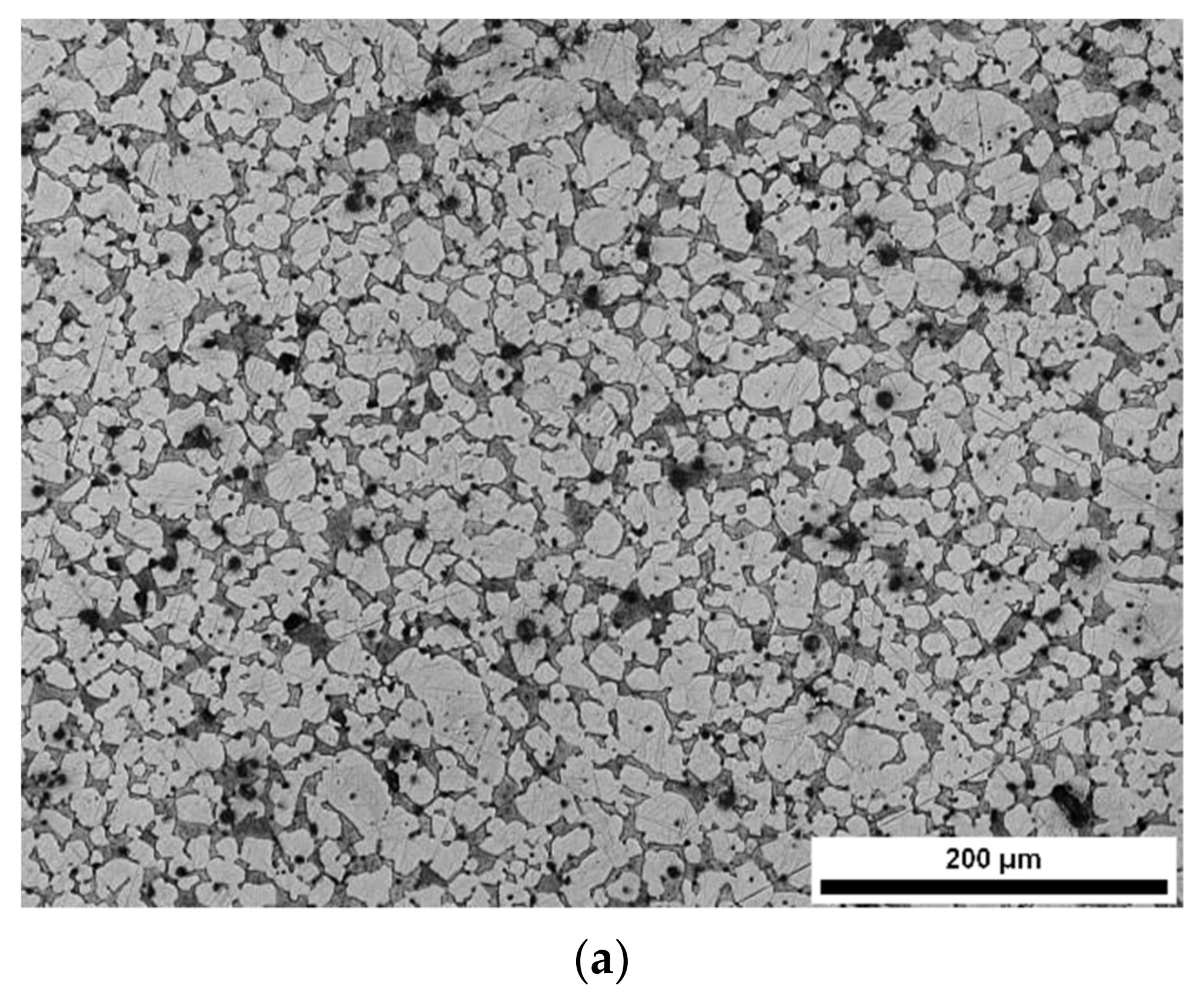
Figure 1. (a) Optical micrograph and (b) SEM micrograph showing the typical microstructure of CuZn39Pb3 (CW614N) brass [50].
Metals 12 00246 g001aMetals 12 00246 g001b
Figure 2. Optical micrographs of the (a) CuZn42, (b) CuZn38As, (c) CuZn36 alloys before heat-treating and (d) CuZn42, (e) CuZn38As, (f) CuZn36 alloys after the heat-treatment process [25].
Metals 12 00246 g002
Figure 3. SEM micrographs on longitudinal sections showing the microstructures of (a) CuZn42, (b) CuZn38As and (c) CuZn36, after the selected heat treatment condition [25].
Metals 12 00246 g003
Figure 4. (a) BSE SEM Micrograph showing the dezincification area of a brass component. (b) Detail of (a) [93].
Metals 12 00246 g004
Figure 5. (a,b) Backscattered Electron (BSE) micrographs showing the fracture surface of a brass component showing intergranular morphology, (c) EDS spectrum of the fracture surface showing the presence of oxides. See Reference [93].
Metals 12 00246 g005
Figure 6. Chip morphology of the as-received (AR) and heat-treated (HT) CW510L-CuZn42 (a,b), CW511L-CuZn38As (c,d) and C27450-CuZn36 (e,f) brass alloys [25]. Note: the decrease in Class number denotes improvement in chip morphology [25].
Metals 12 00246 g006
Figure 7. Optical micrographs showing the morphology of chips generated during the machining process of (a) CuZn42, (c) CuZn38As, (e) CuZn36 alloys before heat-treating (AR) and (b) CuZn42, (d) CuZn38As, (f) CuZn36 alloys after the heat-treatment process, HT [25].
Metals 12 00246 g007
Figure 8. Surface topography derived from profilometric measurements: (a) CW510L, as received, (b) CW510L, heat-treated, (c) CW511L, as received, (d) CW511L, heat-treated, (e) C27450, as received and (f) C27450, heat-treated [25].
Metals 12 00246 g008
Figure 9. Diagrams showing the responses of (a) S/N ratios and (b) data means when evaluated against the cutting parameters which optimise the cutting force [50].
Metals 12 00246 g009
Figure 10. Diagrams showing the responses of (a) S/N ratios and (b) data means when evaluated against the cutting parameters which optimise the surface roughness [50].
Metals 12 00246 g010
Table 1. Analysis of variance (ANOVA) for the cutting force [50].
FactorDegrees of
Freedom
Sum of Squares (SS)Corrected Sum of Squares (SS′)VariancePercent Contribution Pp (%)Rank
Cutting Speed319.042518.82546.34753.57284
Depth of Cut3339.5408339.3238113.180364.39921
Feed Rate3108.0831107.866036.027720.47152
Material358.866058.648919.622011.13083
Error191.37462.24280.07230.4257
Total31526.9070526.9070 100.0000
Table 2. Analysis of variance (ANOVA) for the surface roughness [50].
FactorDegrees of
Freedom
Sum of Square (SS)Corrected Sum of Squares (SS′)VariancePercent Contribution Pp (%)Rank
Cutting Speed37.34983.54222.44990.94604
Depth of Cut391.660687.853030.553523.46252
Feed Rate3210.9051207.097470.301755.30851
Material340.410136.602513.47009.77533
Error1924.114939.34531.269210.5078
Total31374.4404374.4404 100.0000
Publisher’s Note: MDPI stays neutral with regard to jurisdictional claims in published maps and institutional affiliations.