Article

Derivation of the Coefficients in the Coulomb Constant Shear Friction Law from Experimental Data on the Extrusion of a Material into V-Shaped Channels with Different Convergence Angles: New Method and Algorithm

by
Igor Bobrovskij
1,*,
Alexander Khaimovich
2,
Nikolaj Bobrovskij
3,
J. Antonio Travieso-Rodriguez
4 and
Fedor Grechnikov
1,2
1
Department of Metal Physics and Aviation Materials, Samara Scientific Center of Russian Academy of Science, 443001 Samara, Russia
2
Department of Engine Production Technology, Samara National Research University, 443086 Samara, Russia
3
Department of Equipment and Technology of Machine-Building Production, Togliatti State University, 445020 Togliatti, Russia
4
Department of Mechanical Engineering, Polytechnic University of Catalonia, 08019 Barcelona, Spain
*
Author to whom correspondence should be addressed.
Metals 2022, 12(2), 239; https://doi.org/10.3390/met12020239
Submission received: 11 November 2021 / Revised: 13 January 2022 / Accepted: 14 January 2022 / Published: 27 January 2022
(This article belongs to the Special Issue Advances in Plastic Deformation Technologies)

Abstract

:
The combined Coulomb constant shear friction law is widely used in commercial and research software for the finite-element analysis (FEA) of metalworking and is naturally more flexible and hence, more relevant to real-life manufacturing than the individual Coulomb and constant shear friction laws. In this work, a new mathematical model of coefficients in the Coulomb constant shear friction law for extruding a metal through narrow V-shaped channels with small convergence angles has been developed and evaluated and compared with laboratory measurements. The extrusion of the model material (lead) through narrow V-shaped channels with small convergence angles varying from 0 to 3.5 degrees has been studied. The Coulomb friction coefficient µ and the constant friction factor m appear to be independent of the dimension ratio and are influenced mostly by roughness and range from µ = 0.363 (with lubricant) to µ = 0.488 (without lubricant) and from m = 0.726 (with lubricant) to 0.99 (without lubricant). The relative length dominated by the Coulomb friction law is less than 1%, and the Coulomb’s coefficient of friction can be approximated as ½ the constant shear friction factor for all tested cases. The developed method and algorithm can be used in both FEA of manufacturing processes and efficiency tests for lubricants used in metalworking.

1. Introduction

The critical importance of friction for metal-forming processes and its adverse impacts on wear resistance of dies are well-established. Mathematical modeling of thermo-mechanical and chemical interactions at the workpiece–tool interface and other relevant phenomena directly affecting such key process parameters as productivity, quality, and scrap level relies heavily on the finite element method (FEM) [1,2,3,4] widely used for the analysis (FEA) and optimization of various processes and technologies. FEM, a vital component of commercial and research software, is generally capable of delivering great results, but we need a precise description of the behavior of visco-plastic materials at elevated temperatures and accurate assignment of boundary conditions, especially those related to friction [5,6,7,8,9,10,11].
However, despite impressive progress achieved in both theory and over past decades, there is still significant uncertainty in friction models and their parameters in the case when friction occurs at high temperatures [12]. In most cases, non-linear FEM simulations employ phenomenological friction models [13,14], allowing us to uniquely set the boundary conditions for stresses at the workpiece–tool interface via the friction coefficients that greatly improve the convergence of numerical solutions for strongly deformed parts of complex geometries at reasonable computational costs. In view of these circumstances, the correct choice of the friction model and accurately determining the corresponding friction coefficients are a must in the case when a real-life manufacturing process is being simulated.
In the modeling of bulk metal forming, there are a few options to choose from, such as the Coulomb friction law [15,16,17], the constant shear (Siebel) friction law [18,19,20,21,22,23,24], both Coulomb and constant shear friction laws [25,26], general ones [27,28,29] or the integrated law, i.e., Coulomb constant shear friction law [9,14,30,31,32,33]. Being naturally more flexible and, hence more relevant to real-life manufacturing than conventional Coulomb and constant shear friction laws, the Coulomb constant shear friction law is widely used in FEA of metalworking. Here, it is important to note that a fairly common approach to deduce the Coulomb constant shear friction law coefficients by equating calculated and measured total power–energy properties can lead to large uncertainty in the flow stress and strain rates that in turn may result in fatal errors in the design of dies.
In this work, a new mathematical model of the Coulomb constant shear friction coefficients for extruding a metal through narrow V-shaped channels with small convergence angles was derived based on an approximate solution of the equilibrium equations of elasticity, the kinematically admissible velocity field, and the distribution of tangential stresses in the plastic deformation zone meeting realistic physics-based boundary conditions. Based on the above-mentioned model, the algorithm of the derivation of the Coulomb constant shear friction law coefficients from laboratory measurements was developed.
In order to determine the friction coefficients, classical experiments on the upsetting of a ring-shaped workpiece between flat plates have been performed [25,26,34,35]. In [36], a method of the derivation of the friction coefficients from measurements on the upsetting of a cylindrical workpiece at high strain rates was reported. Different tests to determine friction coefficients under different forming conditions have been developed on the basis of extrusion processes [8,9,21,23,24,32,33], especially when other methods, such as the ring compression test, are not suitable for metal-forming processes where the surface expansion is high [18]. Some examples are the double-cup extrusion test [19], the boss and rib test [20], backward extrusion [37], or combined forward–backward extrusion [23], among others.
However, it is important to note that in experiments when both the metal flow and the geometry of the deformation zone are simple, the deformation pressure is low, and the free surface formed due to the deformation is fairly small, and, hence, the friction coefficients/factors are unreliable and cannot be used to simulate real-life manufacturing processes [38]. According to [8,38], measurements of forward and backward extrusion provide much more realistic estimates.
In addition to the Coulomb friction law, the constant shear (Siebel) friction law, general ones or the integrated Coulomb constant shear friction law used in Deform [13] and Abaqus [14] software, other laws have been developed and used in bulking-forming modelling, such as the Levanov friction law used in QForm software [39]. The Levanow friction model represents a generalization of the shear friction model and Coulomb friction model. The similar Wanheim and Bay [2,27,28,29] friction law assumes friction to be proportional to the normal contact pressure at low normal pressure, but progressively approaching a constant value at high normal pressure.
In [38,40], experiments on extrusion into narrow lateral radial channels were used to study friction in the case when the contact area between the tool and the workpiece is large.
In a previous study [38], a comparative analysis of the lubricant’s composition influence on the frictional forces was proposed by analyzing the filling of the V-shaped channels of the die. The analysis was carried out by the similarity theory method. In the present study, the Coulomb constant shear friction parameters were derived from laboratory measurements on the extrusion of a model material (lead) into V-shaped channels with different convergence angles using the lower bound limit analysis approach. The flowing into narrow channels formed by die surfaces is critically important for pressure processing of metals, with flowing into the groove of the die streams during hot stamping and into the matrix during drawing being the most typical examples of such processes.
The large contact area and low local deformations typical of these processes have a large impact of friction on the flow pattern. Since friction in the large contact area may differ greatly depending on the conditions of the die surface and changes in the contact pressure, the Coulomb constant shear friction law is better suited for the description of friction than either the Coulomb friction law or the constant shear friction law, and thus, the friction coefficients derived from analysis of the occupancy of narrow V-shaped channels in the present study are more relevant to the real-life manufacturing than those obtained using other methods.
The core idea of the developed method and the main component of its novelty involve the use of a comparative analysis of work of filling channels with different angles of convergence calculated from the experimental data on the volumes of metal extruded into these channels. Depending on the friction coefficients values, different ratios of the lengths of material extruded into the channels are observed. A particular advantage of this method over competitors is its independence of the yield strength, leading to its invariance with respect to the material being processed and independence of the processing conditions due to the simultaneous extrusion into all radial channels during experiments. The developed mathematical model was used to study the influence of the dimension ratio on the extrusion into the channels and Coulomb constant shear friction coefficients. Experiments on bulk-forming process through matrices of special design were carried out with lead chosen for its high visco-elasticity, allowing us to simulate the metal flowing in the stamp during the hot stamping under laboratory conditions. The developed model was evaluated by comparing modeled and experimental friction coefficients by analyzing extrusion into two dies of identical shape but with different, by a dimensional ratio of two, linear dimensions of the forming cavity.

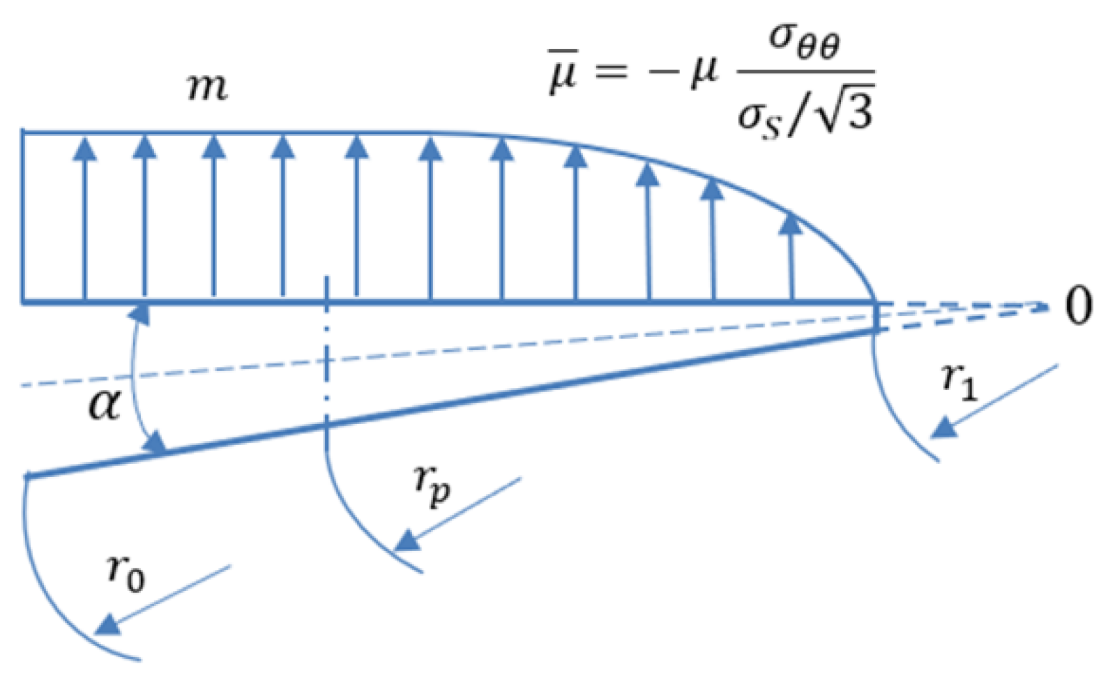
2. Theoretical Simulation of Material Flow into V-Shape Narrow Channels

In this section, easy-to-use analytical equations describing the Coulomb constant shear coefficients as a function of the channel properties and other relevant variables describing extrusion conditions and properties of a material being extruded are derived. The channel height is assumed to be much larger than wider; therefore, the metal flow in the channel can be considered two-dimensional.
The most common friction models used to describe metalworking processes are [11]:
  • the Coulomb friction law:
τ = μ p ,
the constant shear friction model:
τ = m k ,
the generalized friction model [27,28,29]:
τ = f α k ,
where τ is the friction stress, μ is the friction coefficient, p is the normal stress, k = σ s 3 - is the shear stress, f is the friction coefficient under real contact conditions, and α is the ratio of actual and theoretical contact areas.
The tangential stress along the V-shaped-generating lines of the channel is determined by the constant shear friction law,
τ = m σ s 3   at   σ n σ p
and the Coulomb friction law
τ = μ σ n   at     σ n < σ p
Here, σs is the yield strength, σn is the normal stress on the contact surface, and σp is the maximum of σn when the Coulomb friction law changes to the constant shear friction law.
First, a cylindrical coordinate system O(r,θ,z) is introduced in which the plane θ = 0 is the mid-plane of the generating lines of the converging channel (see Figure 1), where θ = α/2, α is the convergence angle of the generating lines, r0 is the radius of the generatrix of the V-shaped channel with entrance thickness s (the radius of the element extruded into the channel with a base length l), r1 is the apex radius of the element extruded into the channel, and r1rr0 is the current radius.
λ = r 0 r 1 is the elongation ratio of the extruded element, and λ l = l s is the relative length of the extruded element to make a transition to dimensionless quantities.
For small angles α (in rad.), the following relationships are used:
r 0 = s α
r 1 = r 0 l
λ = s α s α l = 1 1 α λ l .
According to (1), there is a radius r = rp, at which σn = σp(rp) and, thus, the following condition is met:
μ = m 3 σ s σ p ( r p )  
For narrow channels, i.e., for small α values, the linear distribution law for tangential stress τ along the angle θ is used. By making use of (4), (5), (9) and the boundary conditions τ = 0 at θ = 0; τ = τ, at θ = α/2, we obtain:
{ τ r θ μ σ θ θ 2 θ α , r r p , σ n = σ θ θ ,   where   ( θ = α / 2 ) τ r θ = m σ s 3 2 θ α , r > r p
The equilibrium equation in cylindrical coordinates in the projection onto the axis θ has the following form:
1 r σ θ θ θ + τ r θ r + 2 τ r θ r = 0
where σθθ may be expressed as a product of two functions, σ(θ) and (σ(r) + C0).
σ θ θ ( r , θ ) = σ ( θ ) ( σ ( r ) + C 0 )
After inserting the expressions for the distribution law of the tangential stress (4) and σθθ (6) into the equilibrium Equation (11), Equation (13) is obtained:
d σ ( θ ) d θ σ ( r ) r + μ σ ( θ ) d σ ( r ) d r 2 θ α + 2 μ σ ( θ ) σ ( r ) + C 0 r 2 θ α = 0 or d σ ( θ ) d θ + μ ( d σ ( r ) d r r σ ( r ) + 2 ( 1 + C 0 σ ( r ) ) ) 2 θ α σ ( θ ) = 0
After the integration of (13) over θ, Equation (14) is obtained:
σ ( θ ) = C θ μ θ 2 α ( d σ ( r ) d r r σ ( r ) + 2 ( 1 + C 0 σ ( r ) ) ) .
In the case where θα/2 is small and θ2 is the second-order infinitesimal O(10−2), σ(θ) ≈ Cθ is obtained if the following condition,
C = | d σ ( r ) d r r σ ( r ) + 2 ( 1 + C 0 σ ( r ) ) | 1 O ( 10 1 )
proved below, is met. From (12), with accounting for (14) and (15), Equation (16) is obtained:
σ θ θ = C θ ( σ ( r ) + C 0 )
The typical velocity field of a metal flow in a converging channel is described by the following dependency:
u r = u 0 R 0 c o s θ / r ,                 u θ = u z = 0
and, therefore, the effective strain rate is expressed as:
ε ˙ ¯ = 1 / 2 ε ˙ i j ε ˙ i j = [ 1 / 2 ( 1 + 3 cos 2 θ ) 1 / 2 u 0 r 0 ] / r 2
which at small angles θ = 0…α/2 reduces to:
ε ˙ ¯ = u 0 r 0 r 2
After making use of the constitutive equations:
σ r r = σ s 3 ε ˙ ¯ u r r + σ σ θ θ = σ s 3 ε ˙ ¯ u r r + σ
where σ is the hydrostatic pressure, and the continuity condition for the metal flow is:
u r r + u r r = 0
Finally, Equation (22) is obtained:
σ r r σ θ θ = 2 σ s 3
After inserting (22) and the equation for τ (10) with accounting for (16) into the equilibrium equation for coordinate r:
σ r r r + 1 r τ r θ θ + σ r r σ θ θ r = 0
The stress law is found:
σ r r σ s 3 ( 2 + 2 μ p α ) ln r + C r  
σ θ θ σ s 3 ( 2 + ( 2 + 2 μ p α ) ln r ) + C r
where, according to (10):
{ μ p = m ,   r > r p μ p = μ σ θ θ σ s / 3 ,   r r p
The constant Cr in (24) is derived using the following boundary condition on the free surface
σ r r ( r = r 1 ) = 0
from which the following are obtained:
σ r r 2 σ s 3 ( 1 + μ p α ) ln r r 1 = 2 σ s 3 ( 1 + μ p α ) ln λ σ θ θ 2 σ s 3 ( 1 + ( 1 + μ p α ) ln r r 1 ) σ n = σ θ θ = 2 σ s 3 ( 1 + ( 1 + μ p α ) ln λ ) { μ p = μ , r > r p μ p = 2 m ( 1 + ( 1 + m α ) ln r r 1 ) , r r p
From (28), it follows that in (12):
σ ( θ ) = 2 σ s 3 , σ ( r ) = ( 1 + μ p α ) ln r r 1 , C 0 = 1
After inserting expressions for σ(r) and C0 from (28) into (15), the following inequity is shown:
C < 2 ( 1 + 1 ln r r 1 ) 1 O ( 10 1 )
if r0r > r1 holds identically, assumption (15) is proved to be true. The upper limit of C is shown in Figure 2.
As can be seen in Figure 2, the value of C asymptotically tends to zero when the elongation coefficient increases.
Contact pressure σn decreases with decreasing radius r. After the radius reaches r = rp corresponding to λ p = r p r 1 , a transition from the constant shear friction law to the Coulomb friction law occurs:
τ r θ = μ 2 σ s 3 ( 1 + ( 1 + m α ) ln λ p ) 2 θ α = m σ s 3 2 θ α
and therefore:
μ = m 2 ( 1 + ( 1 + m α ) ln λ p )
The channel numbers associated with the index are denoted as i = 1…N.
In accordance with (8):
ln ( λ p ) = ln ( 1 1 λ l α ) = ln ( 1 λ l α )
where λ l = r 0 r p s .
The expansion of the logarithm (33) into the Maclaurin series yields:
ln ( λ p ) = n = 1 ( α λ l ) n n   at   α λ l 1
For channel 1, let α1 → 0, and at small angle α1 (λp1λ) 1. In this case:
ln α 1 0 λ p 1 = α 1 λ l 1 0
and (32) transforms into:
μ α 1 0 = m 2 ( 1 + λ l 1 m )
where λl1 = (r01rp1)/s is the relative length for channel 1.
Since μi is independent of angle αi, the following condition
μ i = μ j = μ
should be met at any i, j = 1…N.
Figure 3 presents the Coulomb friction coefficient vs. the constant shear friction coefficient at λl1 = 10.
Elongation coefficients λpi for each channel can be found from:
λ p i = exp ( λ l 1 m 1 + m α i )
which follows from (37) with accounting for (36). It is clear that for channel 1 α1 = 0, λp1 = 1.
Figure 4 presents the dependence of the elongation coefficients λ p i = r p i r 1 i on the convergence angle of channel i and the constant shear friction coefficient at λl1 = 10.
As can be seen in Figure 4, the Coulomb friction zone increases with increasing convergence angle of each channel.
Since the plastic deformations zones at the entrance to each channel i with identical dimensions s and h of the entry hole size are equal, the work of A0i of forcing the metal through the plastic deformation zone at the entrance to channel i is proportional to volume Wi of the material extruded into channel i.
A 0 i = σ m W i W i = ( r 0 i 2 r 1 i 2 ) α i h = r 0 i 2 ( 1 1 / λ i ) α i h
where σm is equal for all channels.
The work regarding the plastic deformation associated with the extrusion into channel i is expressed by Equation (40).
A i = σ m W i + A i ,
where the first term on the right hand side of (40) is the work of deformation before the entrance to channel i and the second is the work of metal forming in channel i.
The case where the length of the extruded section exceeds l = r0rp is considered. Since at r = rp, the constant shear friction law transforms into the Coulomb friction law, the work of the formation of the section extruded into the radial channel has, according to (40), the following equation.
A i = r 0 i α i h ( r 0 i r p i σ r r ( r , μ p ) i d r + r p i r 1 i σ r r ( r , μ p ) i d r ) at     r 1 i r p i r 0 i ;   or   at   1 λ p i λ i . A i = r 0 i α i h r 0 i r 1 i σ r r ( r , μ ) i d r at   λ p i λ i .
After making use of (28), Equation (42) is obtained.
σ r r ( r , μ p ) i = 2 3 σ s ( 1 + m α i ) ln ( r 0 i r ) , r > r p i σ r r ( r , μ p ) i = 2 3 σ s ( 1 + m ¯ i α i ) ln ( r 0 i r ) , r r p i μ ¯ i = 1 r p i r 1 i r 1 i r p i 2 m ( 1 + ( 1 + μ α i ) l n r r 1 i ) d r = 2 m ( 1 + 1 + μ α λ p i 1 ( λ p i ( ln λ p i 1 ) + 1 ) )
Integrating (42) and taking into account the last expression, Equation (43) is obtained.
A i = r 0 i 2 α i h 2 σ s 3 [ 1 + m α i + ( m ¯ i m α i ) ( ln λ i λ p i + 1 ) λ p i λ i ( 1 + μ ¯ i α i ) ln λ i + 1 λ i ] , at   1 λ p i λ i . A i = r 0 i 2 α i h 2 σ s 3 ( 1 + m α i ) ( 1 1 λ i ( ln λ i + 1 ) ) , at   λ p i λ i
Here, it is important to note that due to the minimum energy principle, the work of forming of each radial element/section is equal. Channel i (for example, with minimum α) is filled with micro-volumes of metal ∆Wi until the work of forming Ai(∆Wi) becomes greater than Aj(Wj) in the other channel j, which fills with the metal until Aj(∆Wj) > Am(∆Wm), and therefore, the filling of channel m begins. In this way, all channels are sequentially filled with metal at the equilibrium and the balance of the work conducted and thus, the work of bulk metal formation.
A i = A j = A       is   const
for any i and j.
The master Equation (43) of the developed mathematical model express the work of filling a narrow V-shaped channel by a material under friction following the constant shear Coulomb law with the effective friction coefficient μ ¯ i determined by Equation (42). Based on the developed mathematical model, an algorithm of the derivation of friction coefficients μ and m from experimental data has been developed.

3. Algorithm

The algorithm for calculating the friction coefficients μ and m for the Coulomb constant shear friction law (Algorithm 1) consists of the following steps:
Algorithm 1 The friction coefficients μ and m for the Coulomb constant shear friction law
  • The length of the extruded radial elements li,i = 1…N is measured.
  • The dimensions of the plastic deformation zone and elongation ratio are calculated:
    r 0 i = s α i ,   r 1 i = r 0 i l i ,   λ i = r 0 i r 1 i
  • The initial conditions that define zero approximations for μ and m are set:
    X 0 = { μ 0 , m 0 }
  • Elongation ratio for radius rpi is calculated using Equation (38):
    λ p i = exp ( m 0 / 2 μ 0 1 1 + m 0 / α i )
  • μ ¯ 0 i is calculated using (42) at [r1i, rpi], where friction follows the Coulomb friction law,
    μ ¯ 0 i = 2 m 0 ( 1 + 1 + m 0 α i λ p i 1 ( λ p i ( ln λ p i 1 ) + 1 ) ) .
  • The work of Ai is calculated using (43).
  • The average value and the relative variance for the work of filling the radial channels is computed:
    A ¯ ( μ 0 , m 0 ) = 1 N i = 1 N A i ( μ 0 , m 0 )
    δ ¯ ( μ 0 , m 0 ) = 1 N A ¯ ( μ 0 , m 0 ) i = 1 N ( A i ( μ 0 , m 0 ) A ¯ ( μ 0 , m 0 ) ) 2
  • The (μ, m) values are derived by solving the nonlinear equation:
    arg min δ ¯ ( μ , m ) 0 , 1 < μ < 1 , 0 , 01 < m < 0 , 8 { ( μ , m ) | ( μ 0 , m 0 ) , δ ¯ ( μ , m ) δ ¯ ( μ 0 , m 0 ) }
    that include operations performed at steps 3–7 of the algorithm. The Coulomb constant shear law coefficients calculated here are functions of the convergence angles α1, …, αn channel width at the entrance s, lengths l1, …, ln of the extruded sections, deformation temperature, surface roughness, and lubrication. The evaluation of the algorithm against experimental data is described in the next Section.

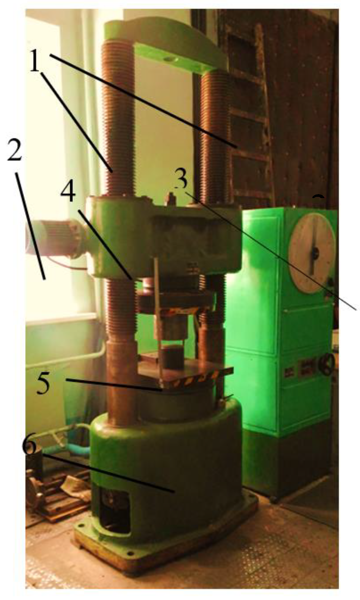
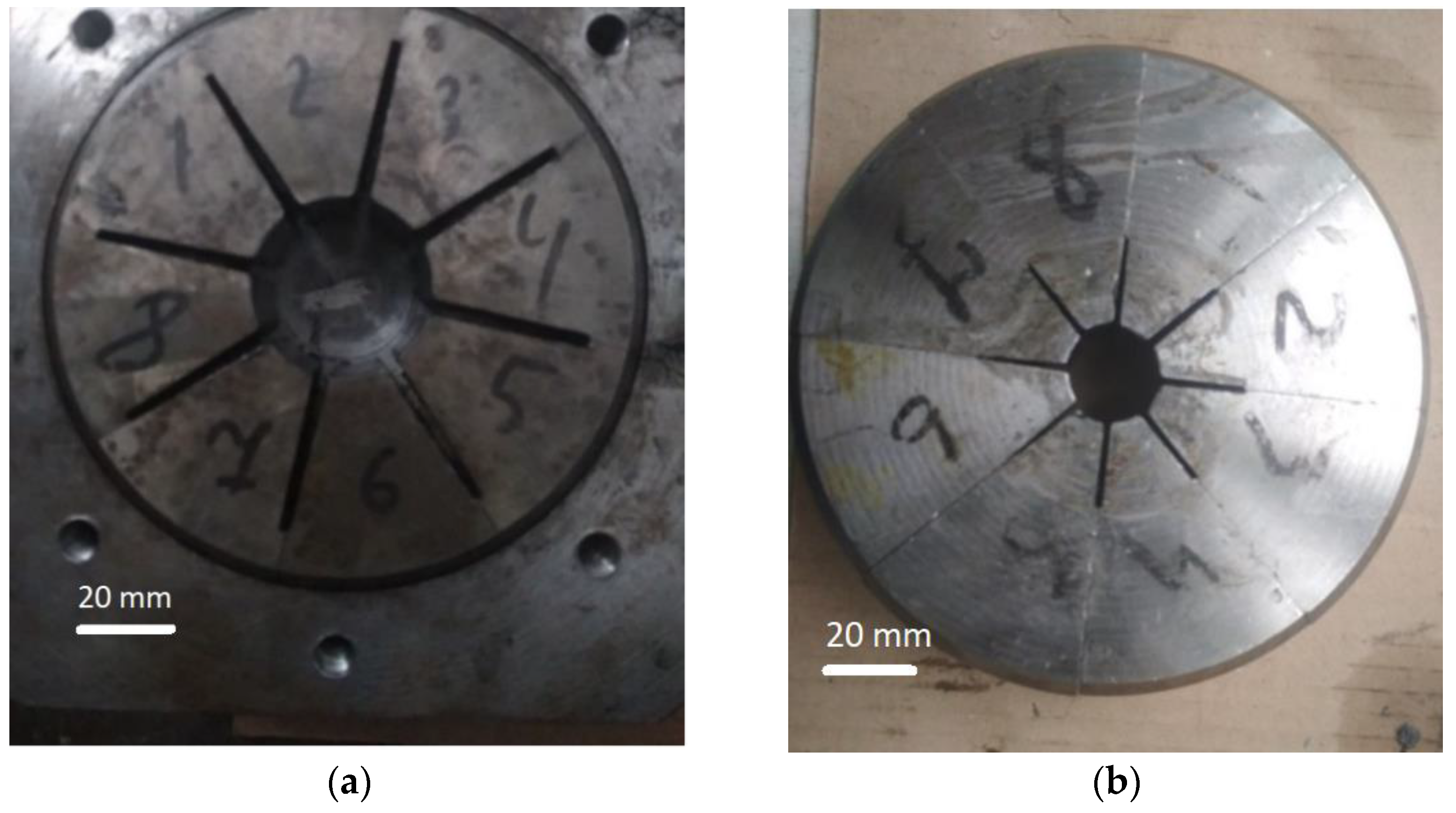
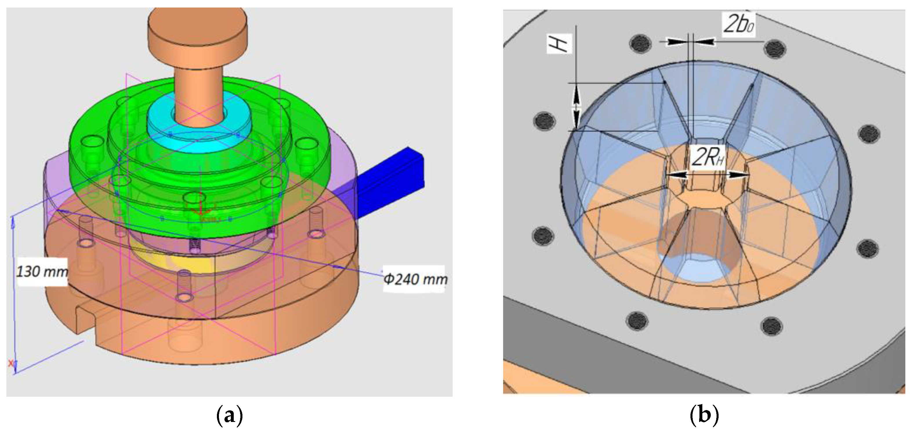
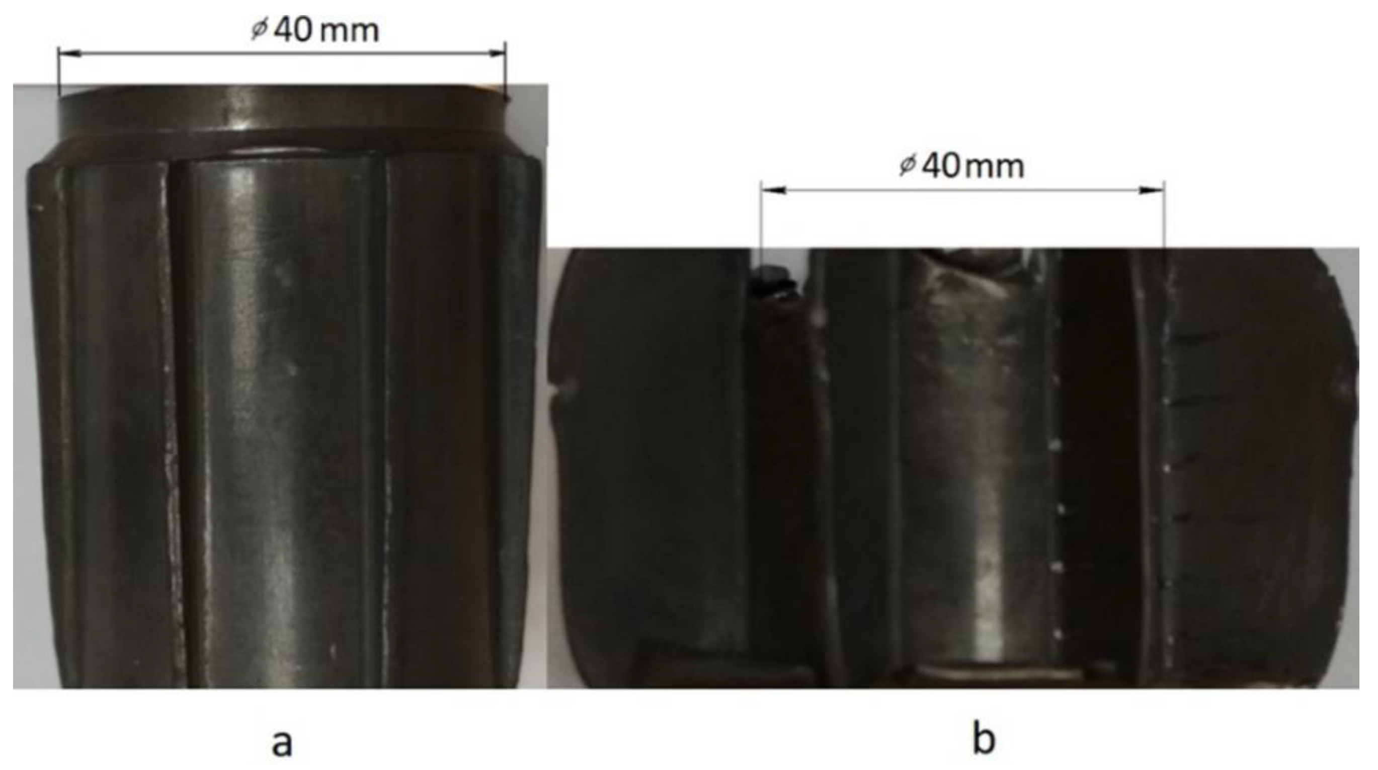
4. Experiments: Methods, Instruments, and Materials

In the experiments, the dependencies of metal volumes extruded in radial channels on the channels’ geometry, length, and dimension ratio were investigated. The model material (led) was extruded into the die equipped with two removable blocks with inserts of eight radial channels. Inserts, shown in Figure 5a,b, provide simultaneous extrusion in eight channels with converging angles varying from 0 to 3.5°. The forming cavities of the blocks provide stamped forgings with dimension ratios of 1 and ½. The average surface roughness Ra of the forming cavities amounts to 2.5 μm for both blocks.
Extrusion of the model material into the forming cavities of each of the two dies was carried out under two different friction boundary conditions, with and without lubricant represented by the oil suspension of graphite powder. Pb was used as a model material because of the lack of significant deformation hardening, which would have introduced an additional error into the experiment.
The experiments were carried out using a hydraulic press PSU-250 (RSCIM, Moscow, Russia) with the maximum force of 250 tons (Figure 6). The press is equipped with a torsion force meter. The process pressure is displayed on the analogous dual-band dial. The loading module of the press is equipped with two vertical screwed columns and an electrically driven mobile traverse.
The die tooling is a block-style die made up of eight inserts (Figure 5). The block was connected to the die bottom die via a special support. The upper part of the die with the slideway was fixed with eight bolts. The force was transmitted through the upper press plate to the punch, which presses on the billet along the slideway (Figure 7).
Measured dimensions of the forgings are summarized in Table 1.
The deforming force, billet height, and depth of filling were measured. The lengths of the extruded sections of forgings were measured in a minimum of seven sections along the height and averaged before being used in calculations of the friction coefficients.

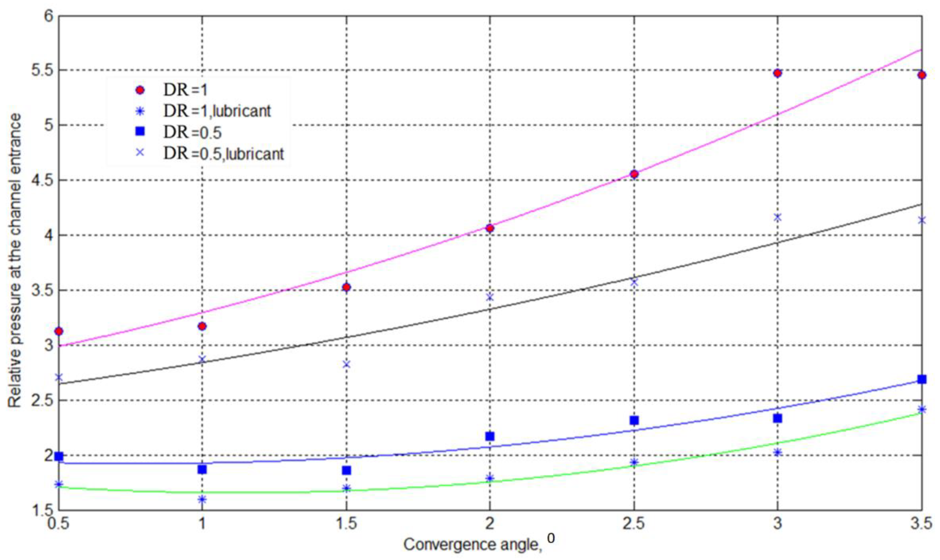
5. Results and Discussion

The forgings photo and the details of the forgings measurements are given in Figure 8 and Table 2.
The friction coefficients were calculated based on the algorithm developed in Section 2. The code for the computations of friction coefficients was developed based on the algorithm of nonlinear models of linear programming [41,42] and implemented in the MatLab 2014b (MathWorks, Natick, MA, USA) environment using the f minimax solver.
The analysis of the computations was carried out accounting for λ l = r 0 r p s and λ l 1 = m 2 μ 1 m for channel 1 with zero convergence angle. The analysis of the master Equations (43) and (42) revealed the following three cases:
λl1  0, i.e., rp   r0.
In this case, metal being extruded into radial channels follows the Coulomb friction law because the size of the constant shear friction zone is very small.
λ l 1 s ( r 0 r 1 ) = l
Here, friction during the extrusion is dominated by the constant shear friction law and, thus, μ dominates friction while m is negligible.
0 λ l 1 < r 0 r 1 s
In this case, the constant shear friction law with coefficient μ controls the range of [r0, rp] while the Coulomb friction law with coefficient m is dominant in the interval [rp, r1].
The results of the channel-filling simulations for different dimension ratios are shown in Table 3. The dependencies of the relative pressure on the convergence angle for the dimension ratios DR = 1 and DR = 0.5 with and without lubrication are presented in Figure 9.
The experimental data clearly indicated that the extrusion of the material into radial channels with small convergence angles was dominated by the constant shear law because the relative length of the Coulomb friction law zone was negligible (see Table 3). In this case, friction was proportional to the normal contact pressure on the channel walls. For dimension ratio DR = 0.5, the higher number of high values of the relative pressures at the entrance to the radial channels in the case of extrusion with lubricant vs. extrusion without lubricant is explained only by larger volumes of extruded material in the first case (see Figure 9).
The Coulomb friction coefficients calculated for the model material appeared to be independent of the dimension ratio, influenced mostly by roughness and ranging from 0.363 to 0.488. The lubrication provided more stable extrusion conditions as evidenced by the lower relative error than in the case when no lubricant was applied. However, lubrication did not significantly affect the length of the constant shear friction law zone. Contact pressure played a key role here, in agreement with the Coulomb law friction. High values of the friction coefficient can be explained by the specific properties of the model material such as low yield stress and high viscosity.
Recent studies tried to establish an approximate relationship between μ and m [15,16,43,44,45,46]. Molaei et al. [44], proposed the following relation based on FEM simulations of double cup extrusion and barrel compression tests, which provided better accuracy than some other relationships:
μ = m 0.9 2.72 ( 1 m ) 0.11
Dixit and Narayanan [45] obtained the die-pressure distributions in the plane-strain upsetting of a specimen of height h and width w for Coulomb and constant friction models. Based on this study, Dixit et al. [46] after several simplifications, obtained the following result:
m = 2 μ + 2 μ 2 w h
for ( μ w / h ) 1 ,   m 2 μ [46].
Zhou et al. [39], in FE simulation of sideways extrusion, adopted the Levanov friction model. When normal contact pressure was low ( σ n σ s < 0.5 ) Levanov’s friction stresses were close to those of the Coulomb friction model with a friction factor m ≈ 2μ. Here, m = 0.9 was assumed for the Levanov friction law in the simulation as no lubrication was applied in extrusion practice.
Zhang et al. [16] used a load-curve slope in a T-shape compression test to determine the friction factor/coefficient of the constant friction/Coulomb friction model under lubricated conditions and found that m 2.3μ.
The comparable results of [2,16,44,45,46] in experiments for the analytical calculation of friction law parameters for extruding metal into narrow V-shaped channels are presented in Table 3, with dependence (32). This analysis showed that it possible to extend the relationship between m and its equivalent μ to the process of filling narrow channels with a large contact area, which, for example, allows one to calculate the forging flash formation when designing finishing dies. The importance of converting these factors to each other is specifically highlighted to introduce the frictional conditions in some professional and commercial finite element software.

6. Conclusions

An accurate assignment of friction boundary conditions is critically important for FEM analysis of metal forming. The accurate description of friction laws and their coefficients is key for the accurate assignment of the friction boundary conditions. In this work, we developed a mathematical model of extrusion into narrow V-shaped channels with friction following the Coulomb constant shear friction law and an algorithm, implemented in the MatLab environment, for the derivation of the friction coefficient from experimental data. Since friction in the large contact area may differ greatly depending on the conditions of the die surface and changes in the contact pressure, the Coulomb constant shear friction law is better suited for the description of friction during metal forming than the individual Coulomb friction and constant shear friction laws, and thus, the friction coefficients derived from experiments on extrusion into narrow V-shaped channels are relevant directly to real-life manufacturing.
The main results of the present work are given below:
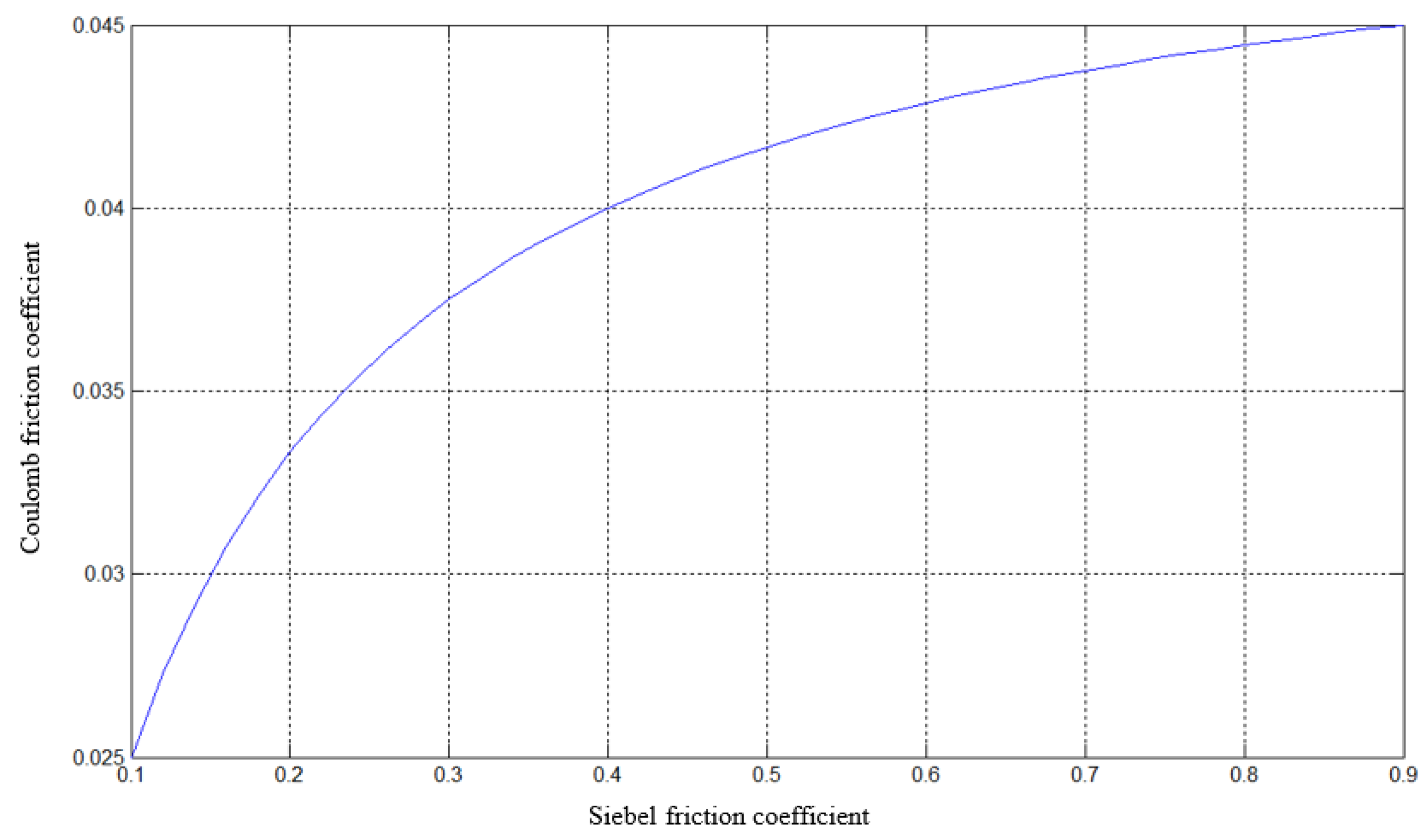
  • A new mathematical model of coefficients in the Coulomb constant shear friction law for extruding a metal through narrow V-shaped channels with small convergence angles has been developed and evaluated against laboratory measurements. The model is based on an approximate solution of the two-dimensional elasticity problem for equilibrium equations, the kinematically admissible velocity field, and the distribution of tangential stresses in the plastic deformation zone that meet certain boundary conditions. For the zone where a transition from the Coulomb friction law to the constant shear friction law occurs, analytical formulas relating the corresponding friction coefficients have been derived.
  • An algorithm of the derivation the Coulomb constant shear friction law coefficients from experimental data on the extrusion of a material through narrow V-shaped channels with small convergence angles has been developed.
  • Laboratory experiments on the extrusion of the model material (led) into narrow V-shaped channels with small convergence angles (0–3.5°) have been performed. It was found that in this particular case, friction largely obeys the constant friction law, and contact pressure plays a key role in the metal forming. The Coulomb friction coefficients calculated for the model material appear to be independent of the dimension ratio are are influenced mostly by roughness and range from 0.363 to 0.488. The lubrication provides more stable extrusion conditions as evidenced by the lower relative error than in the case when no lubricant is applied. However, lubrication does not significantly affect the length of the constant shear friction law zone.
The developed mathematical model and algorithm can be used to derive friction coefficients, to assign the friction boundary conditions in FEM simulations of a number of processes such as bulk metal forming, extrusion, and drawing, and for the performance tests of lubricants.
A feature of the present study was the flow formation conditions of structural elements of forging with a large ratio of the metal–die interface area to the extruded volume. This circumstance extends the results of the study to forgings with thin ribbon sections or the flash formation for the complete cavity-filling stage in the finishing dies. The friction plays a significant role in these cases and obeys a constant friction law for most narrow V-shaped channels with a large surface area. Determining the transition region from the constant friction to Coulomb’s law, which depends on the convergence angle of the V-shaped geometry of the forging flash, allows us to more accurately design dies. In this case, a combined law of friction is set when FE-simulating the metal flow.
It should be noted that the considered laws of friction are of a common nature and, for example, can be applied to solving problems of contact interaction in relation to problems of surface plastic deformation.

Author Contributions

Conceptualization, methodology, supervision, I.B.; formal analysis, writing—original draft preparation, A.K.; investigation, writing—review and editing, N.B. and J.A.T.-R.; data curation, visualization, main idea, F.G. All authors have read and agreed to the published version of the manuscript.

Funding

This research was funded by a grant from the Russian Science Foundation (project NO 19-19-00171).

Data Availability Statement

Not applicable.

Conflicts of Interest

The authors declare no conflict of interest.

References

  1. DeGarmo, E.P.; Black, J.T.; Kohser, R.A.; Klamecki, B.E. Materials and Processes in Manufacturing, 11th ed.; Wiley: New York, NY, USA, 2011; p. 1184. [Google Scholar]
  2. Nielsen, C.; Martins, P. Metal Forming: Formability, Simulation, and Tool Design, 1st ed.; Academic Press: Cambridge, MA, USA, 2021; pp. 251–276. [Google Scholar]
  3. Duan, X.; Velay, X.; Sheppard, T. Application of finite element method in the hot extrusion of aluminium alloys. Mater. Sci. Eng. A 2004, 369, 66–75. [Google Scholar] [CrossRef]
  4. Kobayashi, S.; Oh, S.-I.; Altan, T. Metal Forming and the Finite Element Method, 1st ed.; Oxford University Press: New York, NY, USA, 1989; p. 377. [Google Scholar]
  5. Schikorra, M.; Donati, L.; Tomesani, L.; Kleiner, M. The role of friction in the extrusion of AA6060 aluminum alloy, process analysis and monitoring. J. Mater. Process. Technol. 2007, 191, 288–292. [Google Scholar] [CrossRef]
  6. Li, F.; Yuan, S.; Liu, G.; He, Z. Research of Metal Flow Behavior during Extrusion with Active Friction. J. Mater. Eng. Perform. 2007, 17, 7–14. [Google Scholar] [CrossRef]
  7. Abtahi, S. Interface mechanisms on the bearing surface in extrusion. In Proceedings of the Sixth International Aluminum Extrusion Technology Seminar, Chicago, IL, USA, 14–17 May 1996; pp. 125–131. [Google Scholar]
  8. Jooybari, M.B. A theoretical and experimental study of friction in metal forming by the use of the forward extrusion process. J. Mater. Process. Technol. 2002, 125–126, 369–374. [Google Scholar] [CrossRef]
  9. Donati, L.; Tomesani, L.; Schikorra, M.; Ben Khalifa, N.; Tekkaya, A.E. Friction model selection in FEM simulations of aluminium extrusion. Int. J. Surf. Sci. Eng. 2010, 4, 27–41. [Google Scholar] [CrossRef]
  10. Flitta, I.; Sheppard, T. Nature of friction in extrusion process and its effect on material flow. Mater. Sci. Technol. 2003, 19, 837–846. [Google Scholar] [CrossRef] [Green Version]
  11. Tan, X. Comparisons of friction models in bulk metal forming. Tribol. Int. 2002, 35, 385–393. [Google Scholar] [CrossRef]
  12. Liu, G.; Zhou, J.; Duszczyk, J. FE analysis of metal flow and weld seam formation in a porthole die during the extrusion of a magnesium alloy into a square tube and the effect of ram speed on weld strength. J. Mater. Process. Technol. 2008, 200, 185–198. [Google Scholar] [CrossRef]
  13. Fluhrer, J. DEFORMTM 2D Version 8.1 User’s Manual; Scientific Forming Technologies Corporation: Columbus, OH, USA, 2004; p. 288. [Google Scholar]
  14. Dassault Systèmes Simulia Corp. Abaqus 6.11 CAE User’s Manual; Dassault Systèmes Simulia Corp.: Providence, RI, USA, 2011. [Google Scholar]
  15. Tan, X.; Bay, N.O.; Zhang, W. Friction measurement and modelling in forward rod extrusion tests. Proc. Inst. Mech. Eng. Part J J. Eng. Tribol. 2003, 217, 71–82. [Google Scholar] [CrossRef]
  16. Hambleton, J.; Drescher, A. On modeling a rolling wheel in the presence of plastic deformation as a three- or two-dimensional process. Int. J. Mech. Sci. 2009, 51, 846–855. [Google Scholar] [CrossRef]
  17. Wang, C.; Ma, R.; Zhao, J.; Zhao, J. Calculation method and experimental study of coulomb friction coefficient in sheet metal forming. J. Manuf. Process. 2017, 27, 126–137. [Google Scholar] [CrossRef]
  18. Camacho, A.M.; Veganzones, M.; Claver, J.; Martín, F.; Sevilla, L.; Sebastián, M. Determination of Actual Friction Factors in Metal Forming under Heavy Loaded Regimes Combining Experimental and Numerical Analysis. Materials 2016, 9, 751. [Google Scholar] [CrossRef]
  19. Schrader, T.; Shirgaokar, M.; Altan, T. A critical evaluation of the double cup extrusion test for selection of cold forging lubricants. J. Mater. Process. Technol. 2007, 189, 36–44. [Google Scholar] [CrossRef]
  20. Kang, S.-H.; Lee, K.S.; Lee, Y.-S. Evaluation of interfacial friction condition by boss and rib test based on backward extrusion. Int. J. Mech. Sci. 2011, 53, 59–64. [Google Scholar] [CrossRef]
  21. Chen, X.; Wen, T.; Liu, K.; Hong, Y. Test of Friction Parameters in Bulk Metal Forming Based on Forward Extrusion Processes. J. Shanghai Jiaotong Univ. Sci. 2020, 25, 333–339. [Google Scholar] [CrossRef]
  22. Wang, L.; Zhou, J.; Duszczyk, J.; Katgerman, L. Friction in aluminium extrusion—Part 1: A review of friction testing techniques for aluminium extrusion. Tribol. Int. 2012, 56, 89–98. [Google Scholar] [CrossRef]
  23. Hu, C.; Yin, Q.; Zhao, Z. A novel method for determining friction in cold forging of complex parts using a steady combined forward and backward extrusion test. J. Mater. Process. Technol. 2017, 249, 57–66. [Google Scholar] [CrossRef]
  24. Gavrus, A.; Francillette, H.; Pham, D.T. An optimal forward extrusion device proposed for numerical and experimental analysis of materials tribological properties corresponding to bulk forming processes. Tribol. Int. 2012, 47, 105–121. [Google Scholar] [CrossRef]
  25. Zhang, D.; Yang, G.; Zhao, S. Frictional behavior during cold ring compression process of aluminum alloy. Chin. J. Aeronaut. 2020, 34, 47–64. [Google Scholar] [CrossRef]
  26. Zhang, D.; Liu, B.; Li, J.; Cui, M.; Zhao, S. Variation of the friction conditions in cold ring compression tests of medium carbon steel. Friction 2019, 8, 311–322. [Google Scholar] [CrossRef] [Green Version]
  27. Wanheim, T. Friction at high normal pressures. Wear 1973, 25, 225–244. [Google Scholar] [CrossRef]
  28. Wanheim, T.; Bay, N.O.; Petersen, A. A theoretically determined model for friction in metal working processes. Wear 1974, 28, 251–258. [Google Scholar] [CrossRef]
  29. Wanheim, T.; Bay, N. A model for friction in metal-forming processes. CIRP Ann. 1978, 27, 189–194. [Google Scholar]
  30. Zhang, D.-W.; Ou, H. Relationship between friction parameters in a Coulomb–Tresca friction model for bulk metal forming. Tribol. Int. 2016, 95, 13–18. [Google Scholar] [CrossRef]
  31. Zhang, Q.; Felder, E.; Bruschi, S. Evaluation of friction condition in cold forging by using T-shape compression test. J Mater Process. Technol. 2009, 209, 5720–5729. [Google Scholar] [CrossRef]
  32. Zhou, W.; Yu, J.; Lin, J.; Dean, T.A. Effects of die land length and geometry on curvature and effective strain of profiles produced by a novel sideways extrusion process. J. Mater. Process. Technol. 2020, 282, 116682. [Google Scholar] [CrossRef]
  33. Li, G.-J.; Kobayashi, S. Rigid-Plastic Finite-Element Analysis of Plane Strain Rolling. J. Eng. Ind. 1982, 104, 55–63. [Google Scholar] [CrossRef]
  34. Oh, S.; Wu, W.; Tang, J. Simulations of cold forging processes by the DEFORM system. J. Mater. Process. Technol. 1992, 35, 357–370. [Google Scholar] [CrossRef]
  35. Wang, F.; Lenard, J.G. An Experimental Study of Interfacial Friction-Hot Ring Compression. J. Eng. Mater. Technol. 1992, 114, 13–18. [Google Scholar] [CrossRef]
  36. Grechnikov, F.V.; Khaimovich, A.I. The Study of Plastic Deformation at High Strain Rates in Upset Forging of Cylinders. Key Eng. Mater. 2016, 684, 74–79. [Google Scholar] [CrossRef]
  37. Shen, G.; Vedhanayagam, A.; Kropp, E.; Altan, T. A method for evaluating friction using a backward extrusion-type forging. J. Mater. Process. Technol. 1992, 33, 109–123. [Google Scholar] [CrossRef]
  38. Grechnikov, F.; Khaimovich, A.; Alexandrov, S. Estimation of hot stamping lubricant efficiency under dynamic loading conditions. J. Mater. Process. Technol. 2016, 234, 300–308. [Google Scholar] [CrossRef]
  39. Zhou, W.; Yu, J.; Lu, X.; Lin, J.; Dean, T.A. A comparative study on deformation mechanisms, microstructures and mechanical properties of wide thin-ribbed sections formed by sideways and forward extrusion. Int. J. Mach. Tools Manuf. 2021, 168, 103771. [Google Scholar] [CrossRef]
  40. Grechnikov, F.V.; Khaimovich, A.I.; Mikhelkevich, V.; Jiang, C.-P. The Research of Friction Influences on the Formation Process by Lateral Extrusion into Radial Wedge-Type Branches. Key Eng. Mater. 2017, 746, 56–62. [Google Scholar] [CrossRef]
  41. Grace, A.C.W. Computer-Aided Control System Design Using Optimization Techniques. Ph.D. Thesis, University of Wales, Bangor, UK, 1989. [Google Scholar]
  42. Han, S.P. A globally convergent method for nonlinear programming. J. Optim. Theory Appl. 1977, 22, 297–309. [Google Scholar] [CrossRef] [Green Version]
  43. Rao, K.; Sivaram, K. A review of ring-compression testing and applicability of the calibration curves. J. Mater. Process. Technol. 1993, 37, 295–318. [Google Scholar] [CrossRef]
  44. Molaei, S.; Shahbaz, M.; Ebrahimi, R. The Relationship between constant Friction Factor and Coefficient of Friction in Metal Forming using Finite Element Analysis. Iran. J. Mater. Form. 2014, 1, 14–22. [Google Scholar] [CrossRef]
  45. Dixit, U.S.; Ganesh Narayanan, R. (Eds.) Modelling of metal-forming process. In Metal Forming: Technology and Process Modelling; McGraw Hill Education: New Delhi, India, 2013. [Google Scholar]
  46. Dixit, U.S.; Kumar, V.; Petrov, P.; Saprykin, B. Determining Friction and Flow Stress of Material during Forging. In Proceedings of the 24th International Conference on Material Forming (ESAFORM 2021), Liège, Belgium, 14–16 April 2021. [Google Scholar] [CrossRef]
Figure 1. Scheme of the determination of the Coulomb constant shear friction law coefficients. α—convergence angle, r0—radius of the generatrix of the V-shaped channel, r1—apex radius of the element extruded into the channel, rp—transition area radius from constant to Coulomb friction law.
Metals 12 00239 g001
Figure 2. Upper boundary of C as a function of the elongation coefficient.
Metals 12 00239 g002
Figure 3. Coulomb friction coefficient vs. constant shear friction coefficient at λl1 = 10.
Metals 12 00239 g003
Figure 4. The dependence of the elongation coefficients λ p i = r p i r 1 i on the convergence angle (deg) of channel i and the constant shear friction coefficient at λl1 = 10.
Metals 12 00239 g004
Figure 5. Removable blocks with inserts for the simultaneous extrusion in eight channels with converging angles varying from 0 to 3.5° and dimension ratios of (a) 1 and (b) 1/2.
Metals 12 00239 g005
Figure 6. Hydraulic press PSU-250: 1—screwed column; 2—electric motor; 3—analog dial; 4—mobile traverse; 5—top plate; 6—bottom plate.
Metals 12 00239 g006
Figure 7. Die: (a) Assembled representation; (b) Bottom die.
Metals 12 00239 g007
Figure 8. Photo of the forgings at the initial (a) and final (b) stages of deformation.
Metals 12 00239 g008
Figure 9. Dependence of the relative pressure at the entrance to the radial channel on the convergence angle.
Metals 12 00239 g009
Table 1. Size of the replaceable blocks of the die.
ParameterValue
Dimension ratio10.5
Channel thickness at the entrance, 2b0 (mm)1.50.75
Channel width H (mm)4522.5
Outer diameter, 2RH (mm)4020
Channel number1234567812345678
Convergence angle, 2α (°)00.511.522.533.500.511.522.533.5
Table 2. Average (Av.) lengths of radial elements of forgings with different dimension ratios (DRs) under different friction conditions (with and without lubrication).
Deformation ConditionsParameterConvergence Angle (°)
0.00.51.01.52.02.53.03.5
DR = 1, no lubricationAv. length19.4218.3216.9516.9517.2717.1617.6416.30
Dispersion1.4202.0592.3642.3641.503.0902.0501.262
DR = 1, lubricationAv. length10.2010.559.249.279.209.309.189.93
Dispersion1.8710.8153.0031.1940.8420.4860.7340.825
DR = 0.5, no lubricationAv. length10.126.015.345.025.395.365.15.34
Dispersion2.2810.2130.4330.3140.1530.110.0920.092
SF = 0.5, lubricationAv. length12.228.618.297.548.087.697.867.29
Dispersion1.8630.1660.4330.0760.060.2530.0840.181
Table 3. Analysis of the experimental data and evaluation of friction coefficients by means of the developed method.
ParameterDR = 1DR = 0.5
w/o LubricantLubricantw/o LubricantLubricant
1.constant shear friction factor m0.8270.7260.990.74
2.Coulomb friction coefficient μ0.4130.3630.4880.370
3.The relative length dominated by the Coulomb friction law less than 1%
4. δ ¯ ( μ , m ) 0.03740.04180.03590.0263
5.m/μ≈2
Publisher’s Note: MDPI stays neutral with regard to jurisdictional claims in published maps and institutional affiliations.

