
Electrochemical Deposition of CoP and CoNiP as Hard Magnetic Scales in a Position Measurement System


Abstract
:1. Introduction
2. Materials and Methods
2.1. Electrochemical Deposition of Hard Magnetic CoP and CoNiP
2.2. Integrated Fabrication of Hard Magnetic CoP Scales
3. Results
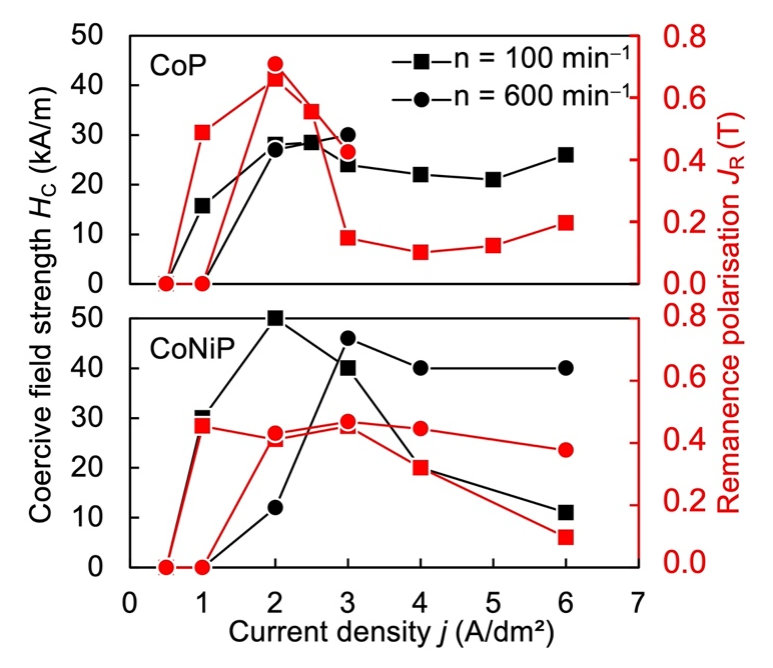
3.1. Hard Magnetic CoP and CoNiP Layers
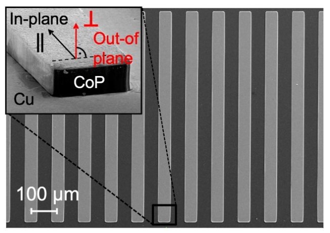
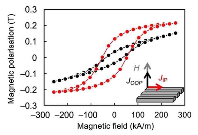
3.2. Hard Magnetic CoP Scales
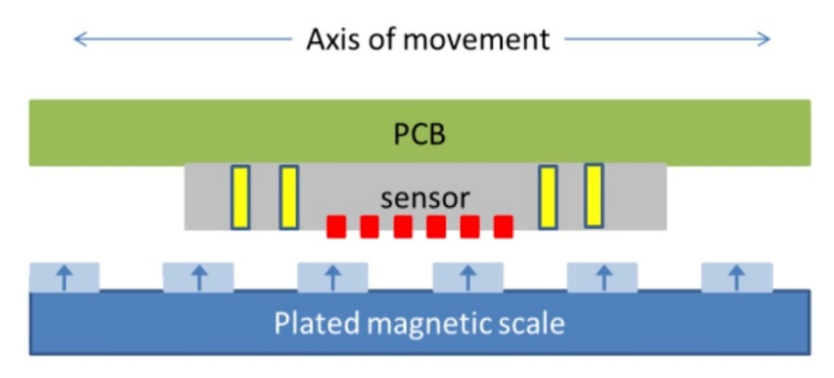
3.3. Assessment of the Magnetic Scale Operation
3.4. Further Planned Material Characterizations
4. Conclusions
Author Contributions
Funding
Institutional Review Board Statement
Informed Consent Statement
Data Availability Statement
Acknowledgments
Conflicts of Interest
References
- Sharma, S.; Radulov, I.; Major, M.; Alff, L. Evolution of Magnetic Anisotropy with Sm Contents in Sm–Co Thin Films. IEEE Trans. Magn. 2018, 54, 11. [Google Scholar] [CrossRef]
- Reimer, T.; Lofink, F.; Lisec, T.; Thede, C.; Chemnitz, S.; Wagner, B. Temperature-stable NdFeB micromagnets with high-energy density compatible with CMOS back end of line technology. MRS Adv. 2016, 1, 209–213. [Google Scholar] [CrossRef]
- Arnold, D.P.; Wang, N. Permanent Magnets for MEMS. J. Micromechanical Syst. 2009, 18, 1255–1266. [Google Scholar] [CrossRef]
- Myung, N.V.; Park, D.-Y.; Yoo, B.-Y.; Sumodjo, P.T.A. Development of electroplated magnetic materials for MEMS. J. Magn. Magn. Mater. 2003, 265, 189–198. [Google Scholar] [CrossRef]
- Paul, J.; Knoll, H.; Lenkl, A.; Tide, R.; Theis, M.; Saumer, M.; Vetter, C.; Piorra, A.; Meyners, D.; Lofink, F.; et al. Hochauflösende Magnetfeldpositionssensoren zur Präzisen Steuerung von Produktionsanlagen. In Proceedings of the MikroSystemTechnik-Kongress, Karlsruhe, Germany, 26–28 October 2015. [Google Scholar]
- Safavi, S.; Walsh, F.C. Elextrodeposited Co-P alloy and composite coatings: A review of progress towards replacement of conventional hard chomic deposits. Surf. Coat. Technol. 2021, 422, 127564. [Google Scholar] [CrossRef]
- Winterstein, V. Magnetische Eigenschaften und Modellierung des Ummagnestisierungsverhaltens Galvanisch Abgeschiedener Anisotroper Kobalt Speicherschichten, 2nd ed.; Verlag ISLE: Illmenau, Germany, 1997. [Google Scholar]
- Guan, S.; Nelson, B.J. Pulse-Reverse Electrodeposited Nanograinsized CoNiP Thin Films and Microarrays for MEMS Actuators. J. Electrochem. Soc. 2005, 152, 190–195. [Google Scholar] [CrossRef]
- Armyanov, S. Crystallographic structure and magnetic properties of electrodeposited cobalt and cobalt alloys. Electrochim. Acta 2000, 45, 3323–3335. [Google Scholar] [CrossRef]
- Kulkarni, S.; Roy, S. Deposition of thick Co-rich CoPtP films with high energy product for magnetic microelectromechanical applications. J. Magn. Magn. Mater. 2010, 322, 1592–1596. [Google Scholar] [CrossRef]
- Oniku, O.D.; Qi, B.; Arnold, D.P. Electroplated thick-film cobalt platinum permanent magnets. J. Magn. Magn. Mater. 2016, 416, 417–428. [Google Scholar] [CrossRef] [Green Version]
- Delbos, S.; Chassaing, E.; Grand, P.P.; Weitbrecht, V.; Bleninger, T. Controlled Mixing and Transport in Comb-Like and Random Jet Array Stirring Systems, in Advanced Topics in Mass Transfer; El-Amin, M., Ed.; IntechOpen: London, UK, 2011. [Google Scholar] [CrossRef]
- Cho, H.J.C.; Bhansali, S.; Ahn, C.H. Electroplated thick permanent magnet arrays with controlled direction of magnetization for MEMS application. J. Appl. Phys. 2000, 87, 6340–6342. [Google Scholar] [CrossRef]
- Hsiao, C.-J.; Hsiao, H.-S.; Tseng, C.-Y.; Chang, J.-Y.; Sung, C.-K.; Wang, S.-C.; Chin, T.-S. Enhancement in (002) texture of electroplated Co-based hard magnet layers. AIP Adv. 2017, 7, 0562102–0562106. [Google Scholar] [CrossRef] [Green Version]
- Samwel, E.O. Magnetic Characterisation of Recording Materials: Design, Instrumentation and Experimental Method. Ph.D. Thesis, University Twente, Enschede, The Netherlands, 1995. [Google Scholar]
- Dobrynin, A.; Dempsey, N. Experimental determination of the magnetization dependent part of the demagnetizing field in hard magnetic materials. Appl. Phys. Lett. 2010, 97, 1925061–1925063. [Google Scholar] [CrossRef]
- Cojocaru, P.; Magagnin, L.; Gómez, E.; Vallés, E. Electrodeposition of CoNi and CoNiP alloys in sulphamate electrolytes. J. Alloy. Compd. 2010, 503, 454–459. [Google Scholar] [CrossRef]
- Emerson, R.N.; Kennady, C.J.; Ganesan, S. Effect of Phosphorous Source Material on the Electrodeposition of CoNiP Magnetic Films. J. Appl. Sci. 2006, 6, 227–232. [Google Scholar] [CrossRef]
- Mirzamaani, M.; Romankiw, L.; McGrath, C.; Karasinski, J.; Mahlke, J.; Anderson, N.C. Correlation of structure and magnetic properties of thin CoP films. J. Electrochem. Soc. 1988, 135, 2813. [Google Scholar] [CrossRef]
- Ciudad, D.; Prieto, J.L.; Lucas, I.; Aroca, C.; Sanchez, P. Optimization of magnetic properties of electrodeposited CoP multilayers for sensor applications. J. Appl. Phys. 2007, 101, 043907. [Google Scholar] [CrossRef]


| Chemical | Concentration (mol L−1) |
|---|---|
| Cobalt sulfate (CoSO4 6H2O) | 0.12 |
| Sodium hypophosphite (NaH2PO2 2H2O) | 0.06 |
| Boric acid (H3BO3) | 0.49 |
| Sodium sulfate (Na2SO4) | 0.16 |
| Sodium saccharin (C7H4NO3SNa2 H2O) | 0.01 |
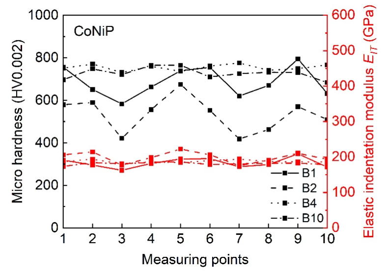
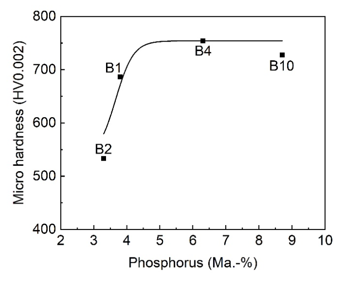
| Co (Ma.-%) | Ni (Ma.-%) | P (Ma.-%) | |
|---|---|---|---|
| B1 | 82.2 | 9.2 | 3.8 |
| B2 | 81.9 | 10.0 | 3.3 |
| B4 | 78.0 | 12.9 | 6.3 |
| B10 | 68.5 | 19.9 | 8.7 |
Publisher’s Note: MDPI stays neutral with regard to jurisdictional claims in published maps and institutional affiliations. |
© 2022 by the authors. Licensee MDPI, Basel, Switzerland. This article is an open access article distributed under the terms and conditions of the Creative Commons Attribution (CC BY) license (https://creativecommons.org/licenses/by/4.0/).
Share and Cite
Theis, M.; Bill, T.; Knoll, H.; Starke, P.; Saumer, M. Electrochemical Deposition of CoP and CoNiP as Hard Magnetic Scales in a Position Measurement System. Metals 2022, 12, 235. https://doi.org/10.3390/met12020235
Theis M, Bill T, Knoll H, Starke P, Saumer M. Electrochemical Deposition of CoP and CoNiP as Hard Magnetic Scales in a Position Measurement System. Metals. 2022; 12(2):235. https://doi.org/10.3390/met12020235
Chicago/Turabian StyleTheis, Martin, Tobias Bill, Heiko Knoll, Peter Starke, and Monika Saumer. 2022. "Electrochemical Deposition of CoP and CoNiP as Hard Magnetic Scales in a Position Measurement System" Metals 12, no. 2: 235. https://doi.org/10.3390/met12020235
APA StyleTheis, M., Bill, T., Knoll, H., Starke, P., & Saumer, M. (2022). Electrochemical Deposition of CoP and CoNiP as Hard Magnetic Scales in a Position Measurement System. Metals, 12(2), 235. https://doi.org/10.3390/met12020235