Article

Self-Supporting Structures Produced through Laser Powder Bed Fusion of AlSi10Mg Alloy: Surface Quality and Hole Circularity Tolerance Assessment

by
Andrea El Hassanin
* and
Antonino Squillace
Department of Chemical, Materials and Production Engineering, University of Naples “Federico II”, P.le Tecchio 80, 80125 Naples, Italy
*
Author to whom correspondence should be addressed.
Metals 2022, 12(12), 2083; https://doi.org/10.3390/met12122083
Submission received: 25 October 2022 / Revised: 1 December 2022 / Accepted: 2 December 2022 / Published: 4 December 2022
(This article belongs to the Special Issue Additive Manufacturing of Light Metal Alloys)

Abstract

:
In the context of the Design for Additive Manufacturing (DfAM), the elimination and/or reduction of support structures for the parts is a key issue for process optimization in terms of sustainability and surface quality. In this work, the assessment of the surface quality of overhanging thin walls and unsupported holes with different diameters (4, 6, 8 mm) was carried out through confocal microscopy, SEM-EDS analysis and CMM measurements. To this aim, two different types of AlSi10Mg alloy parts were produced with the L-PBF technology, having self-supporting features such as thin walls and holes with different overhang angles. The results showed that (i) unsupported, down-facing surfaces can be printed consecutively without supports up to a 30° overhang angle and with a surface roughness (Sa) ranging from 3 to 40 µm; (ii) unsupported holes can be produced as well, having a mean circularity tolerance ranging from 0.03 to 0.55 mm, regardless of the diameter value; (iii) density and microstructure analysis both revealed that the parts’ integrity was not affected by the design choices.

1. Introduction

Over the last two decades, the laser powder bed fusion (L-PBF) technology has proven to be quite attractive due to its undoubted advantages over the more traditional manufacturing routes [1]. Along with the electron beam powder bed fusion (E-PBF) and the laser-engineered net shaping (LENS®) technologies, L-PBF represents one of the most studied and promising Additive Manufacturing (AM) processes, especially for the metal parts market [2,3]. As for all the AM processes, parts’ design flexibility, material waste reduction and the large availability of materials represent only a small number of the remarkable benefits of L-PBF over the more traditional processes based on material removal [1]. However, at the same time, a number of process drawbacks have been pointed out and they are still under investigation today. From the point of view of the process quality, it is well established that the L-PBF process, due to the huge number of process variables involved simultaneously, produces parts that are sensitive to defects, such as improper densification, cracks and delamination, high surface roughness and anisotropic microstructures [1,4,5]. On the other hand, at the part design stage, the pursued choices might mitigate or amplify the aforementioned weaknesses [6]. In this context, a perfect example of how the design decisions have a direct impact on the part quality is represented by the support structures. Supports can be defined as the sacrificial material used during a print to ensure the feasibility of the process itself, as well as to guarantee the parts’ quality and stability. In the L-PBF process, supports are typically made from, but not limited to, the same material chosen to produce the desired parts, and their use is crucial in some parts’ features, such as downward-inclined surfaces, cavities, overhanging sections and holes [7]. It is easy to understand that, given the high complexity of the problem as a function of the desired part geometry, many academic and industry experts have attempted to optimize the process of placing supports in the design step. In this context, the methods of optimization of a print could be categorized into three fundamental approaches, which can be seen individually or simultaneously: (i) the parts’ positioning and nesting, for which a specific strategy for a given part could determine a reduction in the support material needed, both through their elimination or their reduction in volume; (ii) the optimization of the supports in terms of material used and geometry; (iii) a re-design of the desired part, following the Topology Optimization (TO) approach, that aims to reduce the part’s weight without compromising its integrity and performance. These two fundamental approaches that should be followed to minimize the need for support structures were extensively discussed by [8] in their comprehensive review, whose value is not limited to the L-PBF technology, but extends to all AM processes, showing the different support optimization practices. Experimental evidence that contributed to supporting the approach defined by point (i) was provided by some researchers who tried to improve the printability of L-PBF parts containing ledges and concave or convex surfaces through their proper positioning on the build platform. Using aluminum and titanium alloys, they provided some printability limits for the investigated features [9]. Another piece of experimental evidence was given by [10], trying to assess the printability issues of parts having unsupported holes and base supports, the latter having also different sizes. On the other hand, according to point (ii), many strategies have been investigated and studied, giving, in any case, very useful suggestions and guidelines for designers. Considering, for instance, the support material variable, some researchers have tried to use sacrificial and soluble materials as supports, even for metal parts, both options that represent a novelty in this field, since this approach is more characteristic of polymer parts [11,12]. However, at this stage, these methods are quite limited to a few materials and sometimes induce a consistent post-processing operation. On the other hand, the support geometry variable provides further options. In this case, the optimization goal can be seen as the maximization of the surface-to-volume ratio, but still respecting the main functions of the supports, i.e., aiming to facilitate heat dissipation and avoid warping. A perfect example of this concept is represented by cellular support structures [13,14]. Finally, according to point (iii), the TO approach represents a very intriguing approach as well, as reported by [15] in his review, which describes the general rules to follow and some of the direct industrial applications. Moreover, further improvement approaches of the TO, based on more sophisticated computational methods for the specific case of support minimization, were proposed by [16,17]. Regardless of the specific knowledge contribution, it is also interesting to note that most of the mentioned contributions in this field concern the AlSi10Mg alloy as the feedstock material: as for any other light alloy, the reason for this choice is mostly due to its great performance-over-weight ratio, as well as the good weldability due to the high Si content [18,19]. Therefore, in industrial sectors where reduced weight is a primary target, such as aerospace and automotives, but transport in general, the further optimization of the parts’ production through the elimination and/or reduction of support structures could contribute to further weight reduction and increase the quality of the produced parts [20]. On the other hand, although some of the fundamental design basics providing the best advantages of the use of supports were already provided by the ASTM52911-1:2019 standard [7], the printability limits, not only intended in terms of surface quality but also in terms of the dependency of the supports’ application choices in relation to the density, hardness, microstructure and residual stresses of the produced features [5], can be seen as a not fully explored field. With this premise, and within the context of the L-PBF process, this paper aims to provide, through a comprehensive and systematic study, a contribution to the evaluation of the printability limits of L-PBF-produced AlSi10Mg parts. More specifically, the experimental investigation was based on two case studies: (i) parts made by consecutively built overhanging walls, considered to test the printability limits and the surface roughness of unsupported thin walls; (ii) parts having unsupported holes, also printed using different build angles and with different diameters, to analyze their circularity tolerance.

2. Materials and Methods

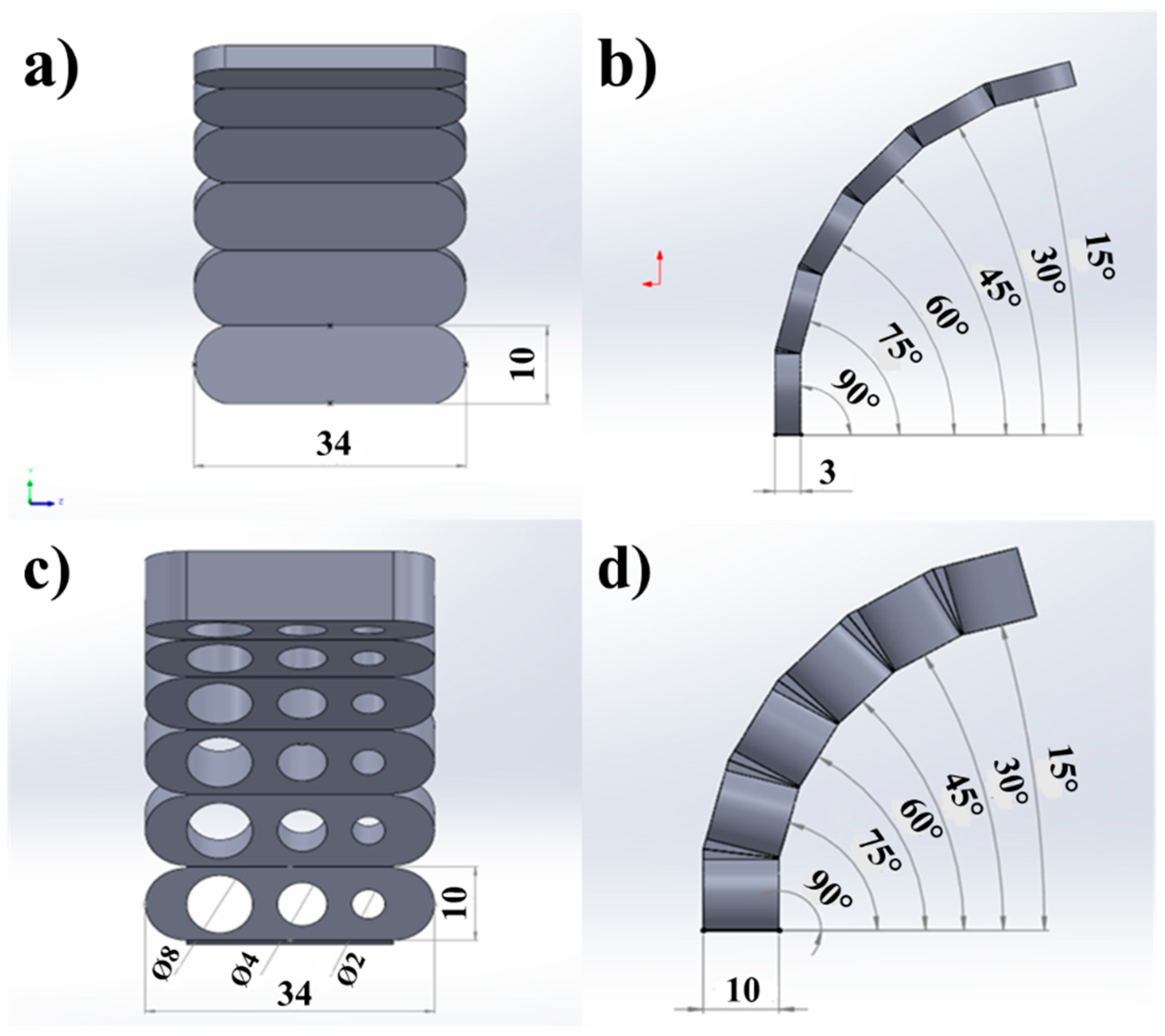
2.1. Structure Design

In this study, it was decided to investigate the printability, the surface quality and the geometric tolerances of the structures reported in Figure 1. More specifically, the investigated structures were designed for two reasons: (i) to assess the printability, without issues or failures, of self-supporting structures, used also to evaluate the overall surface quality as a function of the different overhang angles as well as of the upskin and downskin surfaces (Figure 1a,b); (ii) to assess the circularity tolerance of holes having different diameters, i.e., 4-6-8 mm, considering structures similar to the ones of the previous point but thicker in order to perform measurements at different hole depths (Figure 1c,d). It is worth mentioning that for these latter structures, supports were applied at the topmost overhanging elements (15°, 30°), given the higher weight of the structure in comparison with the one considered for the surface analysis, which would lead to its collapse and thus the failure of the whole job. Nonetheless, considering the excessive weight issue, it was also decided to print separately the elements placed at 0° with respect to the build platform, as shown in Figure 2.

2.2. L-PBF Process

The printability of the structures reported in Figure 1 was assessed through an SLM500 L-PBF machine produced by SLM Solutions GmbH. Figure 2 illustrates the job layout on the build platform, also highlighting the presence of elements oriented at 0° that were placed separately from the structures: this choice was dictated again by the fact the excessive overhanging elements facilitate job failure. Moreover, supports at the base of each printed element were adopted to facilitate the removal of the parts from the platform and three structures were considered for each condition for the sake of repeatability.
The L-PBF process was carried out starting from AlSi10Mg powder feedstocks provided by SLM Solutions. The powders were characterized in terms of shape, chemical composition and particle size distribution (PSD). Figure 3 shows the SEM image of the powder feedstocks, highlighting their widespread distribution and the irregular shape. The former was also quantified according to the ASTM B822 standard [21], presenting the following cumulated volume diameters: Dv(10) = 28.6 µm; Dv(50) = 47.4 µm; Dv(90) = 77.7 µm. Figure 1 reports also the chemical composition of the powders, determined by SEM-EDS analysis (see Section 2.3), suggesting that the composition was compliant with the one expected from the selected alloy. The as-characterized powders were employed for the L-PBF process, using the process parameters suggested by SLM Solutions through their specific exposure profile and reported in Table 1 for the core area (i.e., the bulk of the samples), the upskin and downskin regions [7] and for the contour of each processed layer.

2.3. Characterization Procedure

2.3.1. Confocal Microscopy
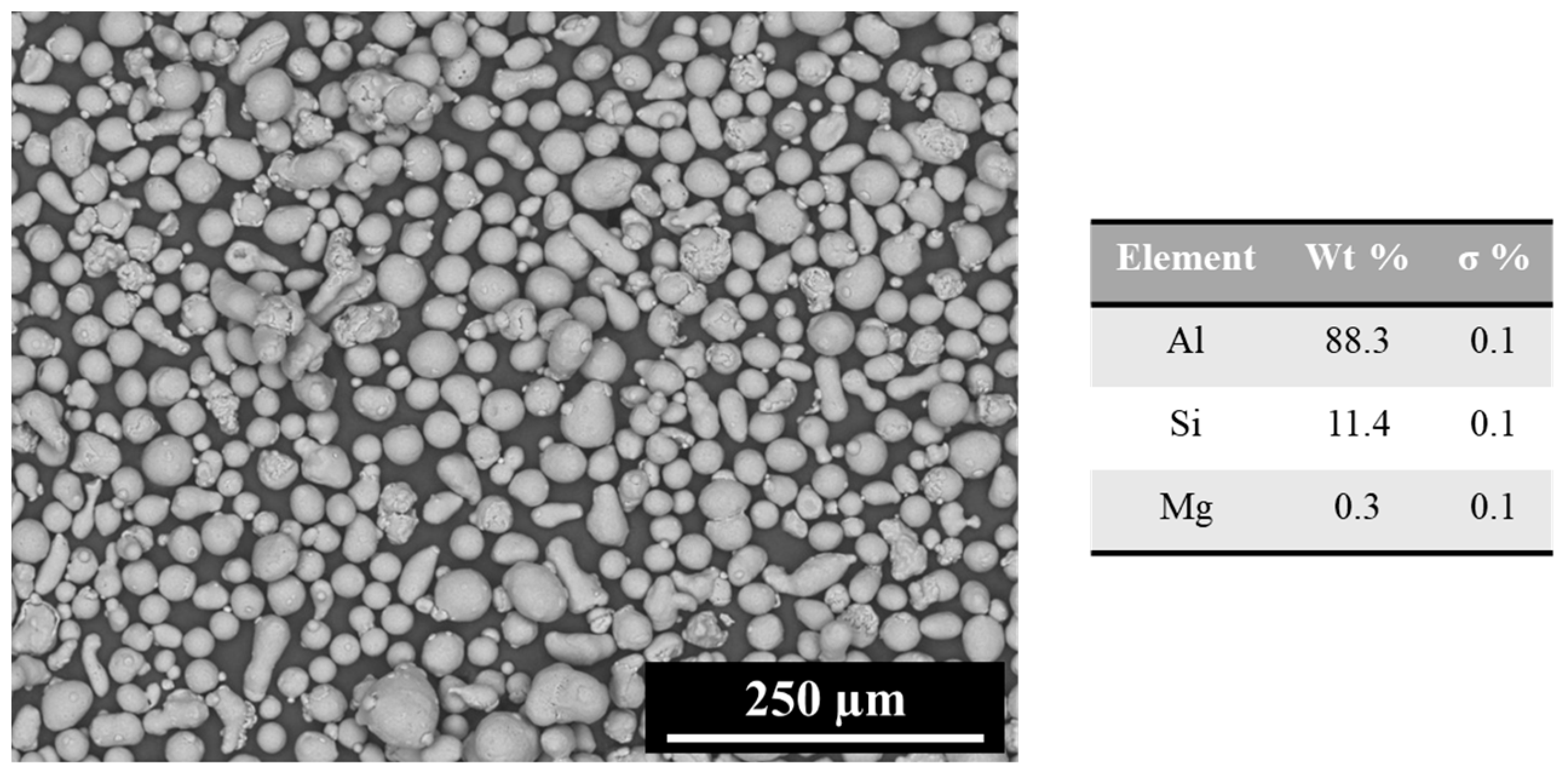
In the case of the self-supported structures designed for the surface quality assessment, the overhanging elements were separated through cutting after the print and removal from the platform. Afterwards, each element was accurately cleaned in an ultrasonic bath of ethanol and dried with compressed air. A Leica DCM3D confocal microscope was used to acquire the surfaces of the specimens, considering a 5 × 5 mm2 area, taken on the center of each of the two sides of the elements, and an overall acquisition depth of 400 µm. In this way, the surface quality was evaluated as a function of the overhang angle and upskin/downskin surfaces for each element and for each of the three printed structures. After the acquisitions, the raw files were elaborated through the LeicaMap v7® software, with the aim to correct tilt and shape errors, as well as to extract the 3D color surfaces and the surface quality indicators, intended in this study as the areal mean roughness (Sa) and areal maximum peak-to-valley distance (Sz), both defined by the ISO 25178 standard [22]. It is worth mentioning that no filtering operations were carried out on the acquired surfaces, given the typical random texture of the L-PBF parts caused by the balling effect [23,24].

2.3.2. SEM-EDS

SEM-EDS analysis was carried out on the powder feedstock, as pointed out in Section 2.2, as well as on the specimens of the self-supporting structures, to support, from a qualitative point of view, the results obtained in Section 2.3.1. A Hitachi TM3000 Tabletop SEM, equipped with a 15 kV electron beam, was used to take images of the surfaces at 100× magnification. To perform the EDS measurements, a SWIFTED3000 probe (Oxford Instruments) was used, equipped with the Aztec® Energy software.

2.3.3. Circularity Tolerance Measurements

In the case of the thicker structures designed for the hole quality assessment, a Zeiss Accura Coordinate Measure Machine (CMM) was used to perform the circularity tolerance evaluation, equipped with a probe whose diameter and length were 3 mm and 20 mm, respectively. With this aim, three circular measures at different depths were performed for each of the holes of the structures. More specifically, each circular measure was composed of the acquisition of eight points along a circle: in this way, the circularity tolerance was defined as the distance between the two measured points that, among the eight ones, were placed at the maximum distance between each other. This setup was repeated at −2, −5, and −8 mm depth, considering as a reference the upskin surface of each overhanging element. Afterwards, the results of the three measures for each hole, repeated also for the three produced structures, were averaged and plotted as the mean and standard deviation tolerance value.

2.3.4. Density and Microstructure Analysis

In addition to the main analysis considered for the surface quality of the thin walls and holes, the density and the microstructure of the parts were analyzed in order to verify whether the challenging printing conditions investigated in this study had an influence on their integrity. Density measurements were carried out according to the ASTM-B962 standard [25], for each overhanging element and for each structure. The results were then expressed as the mean and standard deviation of the collected data. The microstructure of the produced parts was analyzed through optical microscopy, performing macrographs at 100× magnification and using a Zeiss Axioskop 40 Optical Microscope. The observations were carried out after preparing each sample according to the standard metallographic procedure [26] and etching with Keller’s reagent.

3. Results and Discussion

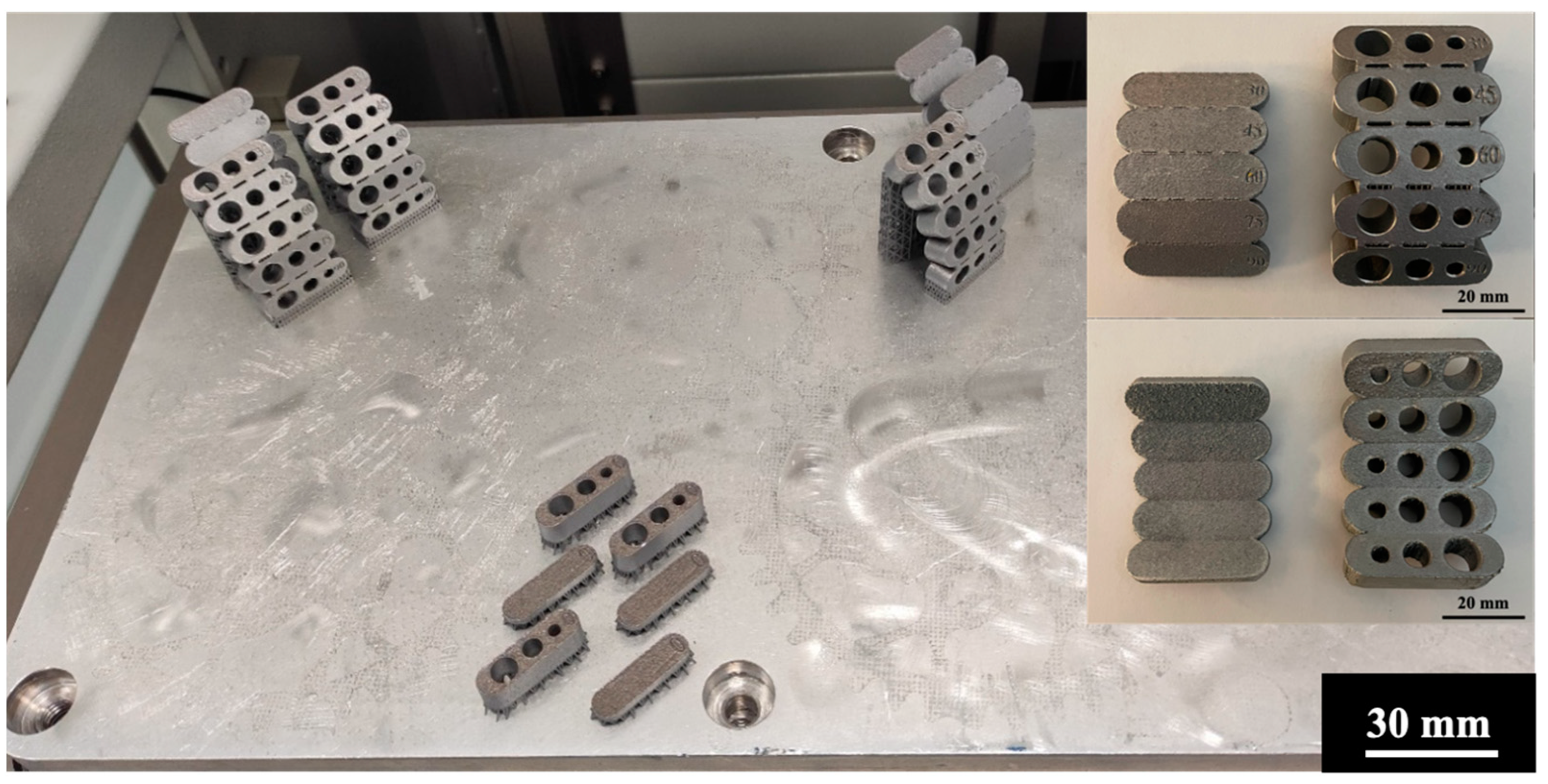
3.1. Printability of the Designed Structures

Figure 4 illustrates the resulting print of the structures designed for this study. The first necessary observation refers to the absence of the 15° overhanging elements: the latter caused the failure of a previous job in which they were included, probably due to the consistent warping of the self-supported structures under the excessive weight. It is worth mentioning that this result, even though the inclined elements were built connected to each other and not separately, was in agreement with the general indication provided by ISOASTM52911-1:2019 [7], as well as with another experimental work reported in the literature [9]. With this premise, in the following results analysis, the 15° overhang angle will be not considered.

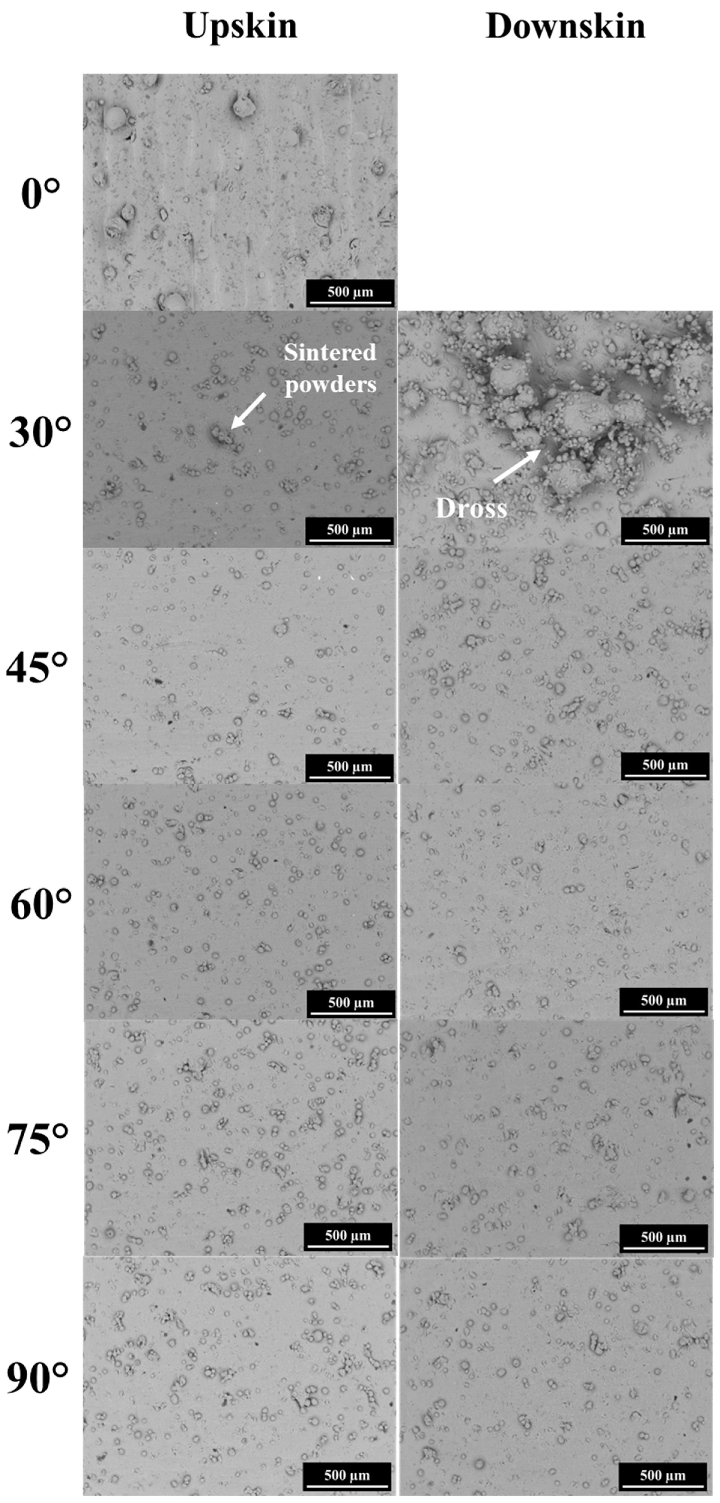
3.2. Surface Quality of the Self-Supported Structures

Figure 5 shows the 3D plots, reported in a false color scale, of the surfaces acquired from each overhanging element for one of the three self-supported structures produced and shown in Figure 4. As expected, the results showed that the downskin surfaces were, in general, worse than the upskin ones [27]. Moreover, according also to the quantitative data reported for the Sa and Sz parameters in Figure 6, it can be noted that the highest downskin–upskin difference was found for the 30° overhanging element, whereas the surface quality differences were mitigated until they were practically absent for the case of the 90° element. These experimental outcomes, in part expected, could be justified considering the contribution of different detrimental phenomena occurring during the build. First of all, the printing of inclined surfaces induced the stair-step effect: apart from the surface quality worsening induced by the mechanism itself, it induces also the filling of the steps’ corners by the sintered powders, caused by the balling effect, as idealized and verified experimentally by [28]. However, in the case of low values of the overhang angle, such as the 30° inclined surface considered in this work, other mechanisms occur whose contributions to the surface quality are more intense compared to the previous ones and justify also the differences in the roughness of the upskin and downskin surfaces. As was well discussed and schematized by [9,27], the printing of overhanging surfaces implies an important issue concerning the laser–matter interaction: as a matter of fact, when the material consolidation occurs with supports or substrates, the energy dissipation provided by the laser and transferred to the material is high. On the other hand, when only loose powders represent the supporting material for the processed feedstock, the thermal conductivity between the consolidating layer and the material lying underneath is considerably lower. Consequently, the melting pool is more unstable due to its higher temperature, and, driven by gravity and capillary forces, the melt tends to entrain the loose powders, resulting in the formation of dross. The latter is the greatest factor responsible for the lower surface quality of downskin surfaces compared to upskin. Moreover, since the 30° overhang angle induced a greater contribution of the stair-step effect, and being also a more critical unsupported condition, the dross formation is enhanced as the detrimental effect of gravity is intensified. Regardless of the specific phenomena involved, it is also interesting to observe that, despite its lower robustness against isolated topological events in comparison with Sa—such as peaks or valleys causing a balling effect in the case of L-PBF-produced surfaces—the Sz evolution showed the same trend as Sa, suggesting therefore the stability of the presented trend.
The results obtained from the confocal microscopy analysis were also supported by the SEM images, reported in comparison in Figure 7. The images showed again the appreciable surface quality difference between the upskin and downskin surfaces for the 30° overhanging element. As a matter of fact, the downskin surface presented a significant number of sintered powders and a sort of crater underneath that indicated the melt instability in that area, supporting therefore the dross formation mechanism proposed by [9]. However, it is worth mentioning that this quality difference, apart from the critical printing condition represented by the 30° element, might be also due to the large feedstock PSD and shape irregularity of some of the powder particles [29]. On the other hand, by observing the images related to the other overhanging surfaces, it can be noted that the quantity of sintered powders tends to be practically the same once the overhang angle is increased.

3.3. Circularity Tolerance Assessment

Figure 8 shows the circularity tolerance plot generated from the data collected from the multiple measures for each hole and the three L-PBF structures. In this case, it is worth mentioning that although the overhang angle was defined in the same way as for Figure 6 (i.e., the angle between the build platform and each downskin surface), the actual inclination of the holes was orthogonal to the former, as their axes were perpendicular to each overhanging element. From the results, it can be stated that (i) the overall measured tolerance ranged from 0.02 to 0.55 mm, indicating then an increase of approximately one order of magnitude when considering the overhanging elements with an angle greater than 30°; (ii) the tolerance reaches its maximum for the 75° overhanging element; (iii) according to the overlapping error bars, there was no specific influence of the hole diameter on the circularity tolerance entity. Concerning the point (i), the appreciable tolerance span measured between the overhanging elements could be ascribed to the stair-case effect, which amplifies the agglomeration of the sintered powders due to the balling effect, as discussed in the previous section to justify the surface quality results [28]. However, considering that the results shown in Figure 7 indicate a major tolerance for the holes inclined in the range 45°–75° in comparison with the one inclined at 30°, other effects must be considered simultaneously, such as gravity, whose contribution could be significantly higher in comparison with the previous case study, as well as the higher sensitivity to hole distortion under the thermal input for the more sloped holes. These latter aspects justify the point (ii), for which the 75° overhanging element was the worst case from both the point of view of the stair-case effect and the higher sensitivity to gravity and hole distortion. Moreover, this discussion is supported again by considering the case of the holes printed at 90° (horizontally inclined): despite the absence of the stair-case effect, the horizontally built holes were the most affected by gravity and distortion, mostly on the upper side of the holes in relation to the sintered powder problem, as shown in Figure 9. Finally, as expected, the lowest circularity tolerance was observed for the holes printed at 0° (vertically inclined), given the negligible contribution of the effects discussed in relation to the previous points.

3.4. Density and Microstructure Analysis

According to the methodology described in Section 2.3.4, the results of the density measurements and the microstructure analysis are reported in Table 2 and Figure 10, respectively. Considering the relative density, calculated as the ratio between the absolute density measured and the one declared by the feedstock manufacturer (2.67 g/cm3), the results suggest that the printing conditions did not influence the densification of the processed material, with values always higher than 99.50%. This result is also visible from the optical macrographs reported in Figure 10, illustrating, for the sake of brevity, only the microstructures of the thin-walled overhanging elements. As a matter of fact, the analyzed specimens presented the well-known microstructure of L-PBF-produced AlSi10Mg parts, with the characteristic molten pools, whose size was not affected in any way by the overhang angle. Moreover, it can be also noted that the processed material presented some small voids (dark and small circular spots visible in Figure 10), which were the result of gas inclusions, most likely produced by the argon gas used for conditioning the chamber. These small defects justify also the imperfect densification of the parts, as is well known in the context of metal AM [23].

4. Conclusions

The focus of this work was the assessment of the printability of self-supporting structures made of AlSi10Mg alloy by means of L-PBF technology. By considering two case studies, the surface quality of overhanging walls and the circularity tolerance of self-supporting holes was analyzed through confocal microscopy, SEM-EDS and CMM measurements, as well as by complementary density and microstructure analysis. Based on the obtained results, the following conclusions can be drawn:
  • Thin and self-supporting structures can be printed, within the same part, without defects and integrity issues with walls having an overhang angle up to 30°. The addition of further overhanging elements inclined at 15° and 0° causes job failure due to the excessive unsupported weight and warping.
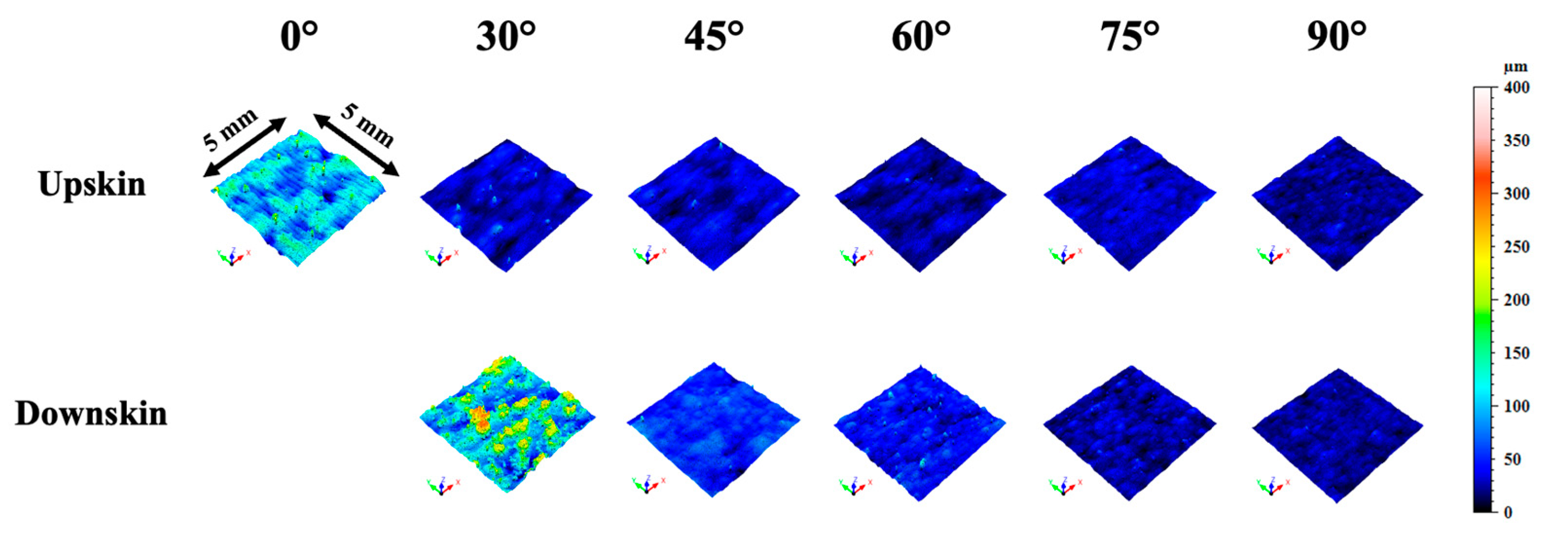
  • The surface quality assessment of thin overhanging walls, carried out through confocal microscopy, showed that the surface roughness decreased as a function of the increasing overhang angle. Moreover, the results showed also, as expected, that the downskin surfaces were rougher compared to the upskin ones. The worst case was represented by the elements with an overhang angle of 30°, with approximate values of Sa and Sz of 40 μm and 400 μm, respectively, whereas the best case was represented by the elements built vertically with respect to the build platform, with approximate values of Sa and Sz of 3 μm and 60 μm, respectively. The main cause of this result was the combination of the stair-step effect, balling effect and, most of all, the formation of dross due to the printing of the unsupported material.
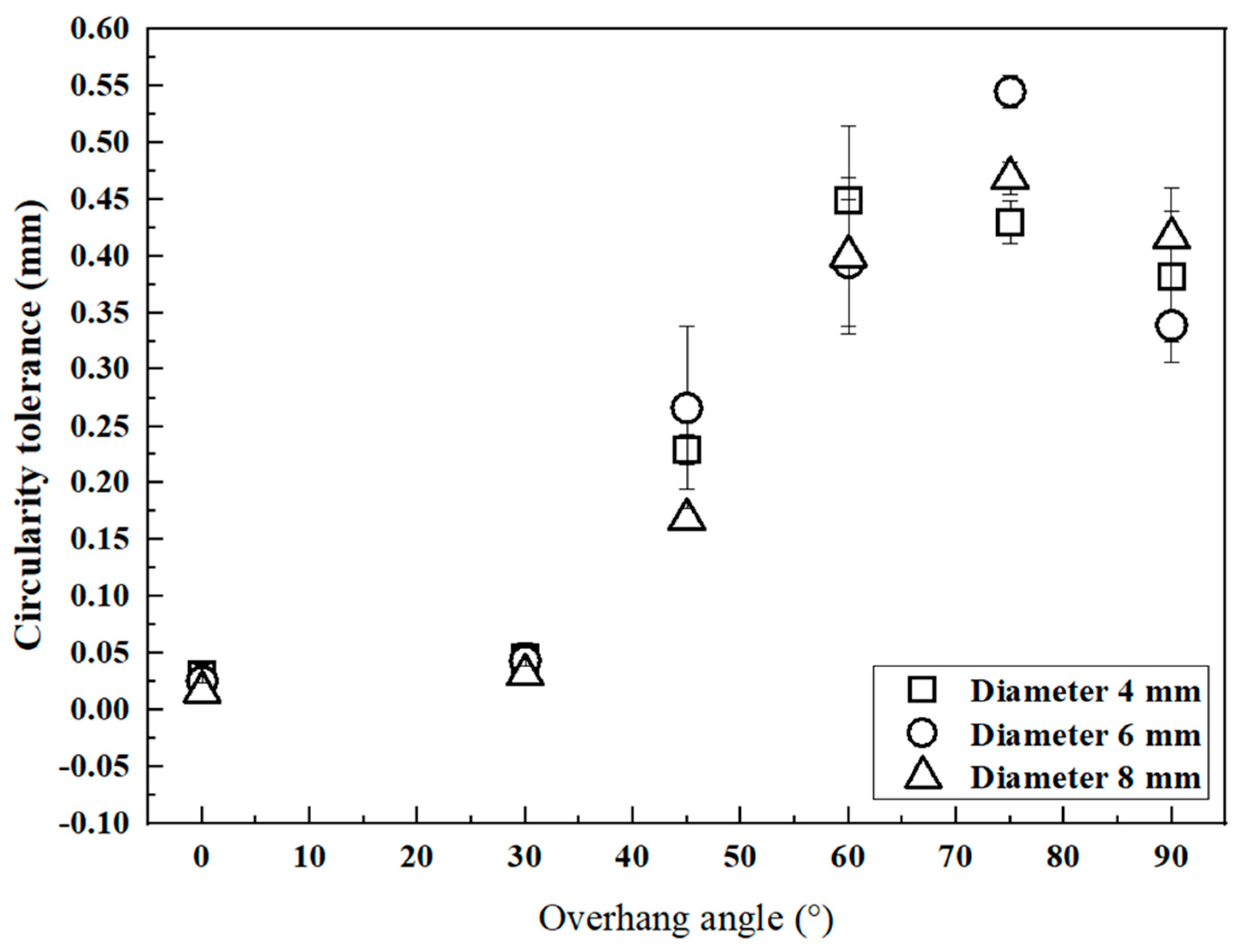
  • The circularity tolerance analysis, carried out on thicker structures having self-supported holes by means of CMM measurements, showed that the overall tolerance span was from 0.03 mm to 0.55 mm, with a maximum value for the 75° overhanging holes and a minimum for the holes oriented vertically with respect to the build platform. The tolerance trend showed that the holes with an overhang angle between 60° and 90° presented the worst quality due to the combined detrimental effects of gravity and the stair-case effect.
  • The holes’ circularity tolerance was not significantly affected by their diameter, within the investigated range: for all three selected diameter values (4, 6, 8 mm), the same detrimental issues occurred, mainly represented by the presence of sintered powders in the upper regions of the holes.
  • The proper densification of the material was not affected in any way by the challenging printing conditions, as proven by the density and the microstructure analysis. The latter showed also the typical microstructure features of the L-PBF-processed AlSi10Mg alloy, with only small gas inclusions present as defects.
  • The obtained results could represent a series of helpful insights for designers, and, as a future remark, they could be extended as a function of different feedstock morphologies and recycling conditions.

Author Contributions

Conceptualization, A.E.H. and A.S.; investigation, A.E.H. and A.S.; writing—original draft preparation, A.E.H.; methodology, A.E.H.; data curation, A.E.H.; supervision, A.S. All authors have read and agreed to the published version of the manuscript.

Funding

This research received no funding.

Acknowledgments

The authors wish to sincerely thank 3Dna S.r.l for their support in the L-PBF experimental campaign through the production of the designed structures.

Conflicts of Interest

The authors declare no conflict of interest.

References

  1. Gibson, I.; Rosen, D.W.; Stucker, B. Additive Manufacturing Technologies, 3rd ed.; Springer: New York, NY, USA.
  2. Sing, S.L.; Yeong, W.Y. Laser Powder Bed Fusion for Metal Additive Manufacturing: Perspectives on Recent Developments. Virtual Phys Prototyp 2020, 15, 359–370. [Google Scholar] [CrossRef]
  3. Yadroitsev, I.; Yadroitsava, I.; Du Plessis, A.; MacDonald, E. Fundamentals of Powder Bed Fusion of Metals; Elesevier: Amsterdam, The Netherlands, 2021. [Google Scholar]
  4. Sanaei, N.; Fatemi, A.; Phan, N. Defect Characteristics and Analysis of Their Variability in Metal L-PBF Additive Manufacturing. Mater. Des. 2019, 182, 108091. [Google Scholar] [CrossRef]
  5. Gouveia, R.M.; Silva, F.J.G.; Atzeni, A.; Sormaz, D.; Alves, J.A.; Pereira, A.B. Effect of Scan Strategies and Use of Support Structures on Surface Quality and Hardness of L-PBF AlSi10Mg parts. Materials 2020, 13, 2248. [Google Scholar] [CrossRef] [PubMed]
  6. Priarone, P.C.; Lunetto, V.; Atzeni, E.; Salmi, A. Laser Powder Bed Fusion (L-PBF) Additive Manufacturing: On the Correlation between Design Choices and Process Sustainability. Procedia CIRP 2018, 78, 85–90. [Google Scholar] [CrossRef]
  7. ISO/ASTM 52911-1:2019; ASTM International Additive Manufacturing—Design—Part 1: Laser-Based Powder Bed Fusion of Metals 1. ASTM International: West Conshohocken, PA, USA, 2019; pp. 1–15. [CrossRef]
  8. Jiang, J.; Xu, X.; Stringer, J. Support Structures for Additive Manufacturing: A Review. J. Manuf. Mater. Process. 2018, 2, 64. [Google Scholar] [CrossRef] [Green Version]
  9. Calignano, F. Design Optimization of Supports for Overhanging Structures in Aluminum and Titanium Alloys by Selective Laser Melting. Mater. Des. 2014, 64, 203–213. [Google Scholar] [CrossRef]
  10. Han, Q.; Gu, H.; Soe, S.; Setchi, R.; Lacan, F.; Hill, J. Manufacturability of AlSi10Mg Overhang Structures Fabricated by Laser Powder Bed Fusion. Mater. Des. 2018, 160, 1080–1095. [Google Scholar] [CrossRef]
  11. Hildreth, O.J.; Nassar, A.R.; Chasse, K.R.; Simpson, T.W. Dissolvable Metal Supports for 3D Direct Metal Printing. 3D Print. Addit. Manuf. 2016, 3, 91–97. [Google Scholar] [CrossRef]
  12. Lefky, C.S.; Zucker, B.; Wright, D.; Nassar, A.R.; Simpson, T.W.; Hildreth, O.J. Dissolvable Supports in Powder Bed Fusion-Printed Stainless Steel. 3D Print. Addit. Manuf. 2017, 4, 3–11. [Google Scholar] [CrossRef]
  13. Hussein, A.; Yan, C.; Everson, R.; Hao, L. Preliminary investigation on cellular support structures using SLM process. In Proceedings of the 5th International Conference on Advanced Research in Virtual and Rapid Prototyping, Leiria, Portugal, 28 September–1 October 2011; pp. 609–612. [Google Scholar]
  14. Hussein, A.; Hao, L.; Yan, C.; Everson, R.; Young, P. Advanced Lattice Support Structures for Metal Additive Manufacturing. J. Mater. Process. Technol. 2013, 213, 1019–1026. [Google Scholar] [CrossRef]
  15. Prathyusha, A.L.R.; Raghu Babu, G. A Review on Additive Manufacturing and Topology Optimization Process for Weight Reduction Studies in Various Industrial Applications. Mater. Today Proc. 2022, 62, 109–117. [Google Scholar] [CrossRef]
  16. Wang, C.; Qian, X. Simultaneous Optimization of Build Orientation and Topology for Additive Manufacturing. Addit. Manuf. 2020, 34, 101246. [Google Scholar] [CrossRef]
  17. Yang, D.; Pan, C.; Zhou, Y.; Han, Y. Optimized Design and Additive Manufacture of Double-Sided Metal Mirror with Self-Supporting Lattice Structure. Mater. Des. 2022, 219, 110759. [Google Scholar] [CrossRef]
  18. Bourell, D.; Kruth, J.P.; Leu, M.; Levy, G.; Rosen, D.; Beese, A.M.; Clare, A. Materials for Additive Manufacturing. CIRP Ann. Manuf. Technol. 2017, 66, 659–681. [Google Scholar] [CrossRef]
  19. Biffi, C.A.; Fiocchi, J.; Tuissi, A. Laser Weldability of AlSi10Mg Alloy Produced by Selective Laser Melting: Microstructure and Mechanical Behavior. J. Mater. Eng. Perform. 2019, 28, 6714–6719. [Google Scholar] [CrossRef]
  20. Campanella, D.; Buffa, G.; El Hassanin, A.; Squillace, A.; Gagliardi, F.; Filice, L.; Fratini, L. Mechanical and Microstructural Characterization of Titanium Gr.5 Parts Produced by Different Manufacturing Routes. Int. J. Adv. Manuf. Technol. 2022, 122, 741–759. [Google Scholar] [CrossRef]
  21. ASTM B822-20; Standard Test Method for Particle Size Distribution of Metal Powders and Related Compounds by Light Scattering. ASTM International: West Conshohocken, PA, USA, 2020. [CrossRef]
  22. ISO 25178-2:2012; Geometrical Product Specifications (GPS)—Surface Texture: Areal Part 2: Terms, Definitions and Surface. ISO BSI Standards Publication: Geneva, Switzerland, 2012.
  23. DebRoy, T.; Wei, H.L.; Zuback, J.S.; Mukherjee, T.; Elmer, J.W.; Milewski, J.O.; Beese, A.M.; Wilson-Heid, A.; De, A.; Zhang, W. Additive Manufacturing of Metallic Components – Process, Structure and Properties. Prog. Mater. Sci. 2018, 92, 112–224. [Google Scholar] [CrossRef]
  24. El Hassanin, A.; Obeidi, M.A.; Scherillo, F.; Brabazon, D. CO2 Laser Polishing of Laser-Powder Bed Fusion Produced AlSi10Mg Parts. Surf. Coat. Technol. 2021, 419, 127291. [Google Scholar] [CrossRef]
  25. ASTM-B962; Standard Test Methods for Density of Compacted or Sintered Powder Metallurgy (PM) Products Using Archimedes’ Principle. ASTM International: West Conshohocken, PA, USA, 2017. [CrossRef]
  26. Geels, K. Metallographic and Materialographic Specimen Preparation, Light Microscopy, Image Analysis, and Hardness Testing; ASTM International: West Conshohocken, PA, USA, 2007; ISSN 9780803142657. [Google Scholar]
  27. Calignano, F.; Iuliano, L.; Galati, M.; Minetola, P.; Marchiandi, G. Accuracy of Down-Facing Surfaces in Complex Internal Channels Produced by Laser Powder Bed Fusion (L-PBF). Procedia CIRP 2020, 88, 423–426. [Google Scholar] [CrossRef]
  28. Strano, G.; Hao, L.; Everson, R.M.; Evans, K.E. Surface Roughness Analysis, Modelling and Prediction in Selective Laser Melting. J. Mater. Process. Technol. 2013, 213, 589–597. [Google Scholar] [CrossRef]
  29. Balbaa, M.A.; Ghasemi, A.; Fereiduni, E.; Elbestawi, M.A.; Jadhav, S.D.; Kruth, J.P. Role of Powder Particle Size on Laser Powder Bed Fusion Processability of AlSi10mg Alloy. Addit. Manuf. 2021, 37, 101630. [Google Scholar] [CrossRef]
Figure 1. L-PBF structures considered for this work: the self-supported structure reported in (a,b) was considered for the surface quality assessment, whereas the one reported in (c,d) was considered for the hole quality assessment (quotes are reported in mm).
Metals 12 02083 g001
Figure 2. (a) Layout of the structures on the building platform of the L-PBF machine and (b) detail of the applied support structures.
Metals 12 02083 g002
Figure 3. SEM image (250×) and chemical composition of the AlSi10Mg powder feedstocks used for the L-PBF process.
Metals 12 02083 g003
Figure 4. L-PBF-produced structures on the build platform. The figure presents also some insets showing the surface quality of the produced parts.
Metals 12 02083 g004
Figure 5. Three-dimensional color surfaces acquired from the overhanging elements of a self-supported L-PBF structure.
Metals 12 02083 g005
Figure 6. Sa and Sz plots reporting the mean values of the parameters measured for the different overhanging elements of the three self-supported L-PBF structures (standard deviation is indicated as ±σ).
Metals 12 02083 g006
Figure 7. SEM images showing the surface morphology comparison between the overhanging elements of a self-supported L-PBF structure (100× magnification).
Metals 12 02083 g007
Figure 8. Circularity tolerance plot reporting the values averaged on both the three depth values for each hole and the three structures considered for repeatability (standard deviation is indicated as ±σ).
Metals 12 02083 g008
Figure 9. Detail of the surface quality of the produced holes, showing the more prominent sintered powders in the upper region of the holes for the vertically printed element (for the adjacent overhanging elements, this effect decreased gradually).
Metals 12 02083 g009
Figure 10. Optical macrographs of the thin L-PBF parts, taken along the build direction (100× magnification).
Metals 12 02083 g010
Table 1. L-PBF process parameters used in this study.
CoreUpskinDownskinContour
Laser power (W)300370220350
Scan speed (mm/s)730133510001650
Hatch distance (mm)0.100.130.130.17
Laser spot (mm)0.08
Layer thickness (mm)0.03
Volumetric energy density (J/mm3)171115 91.788.4
Scan strategyRaster (rotated by 67° between each layer)
AtmosphereAr (purity: 99.99%)
Table 2. Relative density of the produced L-PBF parts.
Overhang Angle (°)Average Relative Density St. Dev (σ)
00.99640.0002
00.99590.0006
450.99560.001
600.99370.0026
750.99550.0005
900.99650.0005
Publisher’s Note: MDPI stays neutral with regard to jurisdictional claims in published maps and institutional affiliations.

