Article

Microstructural and Interfacial Characterization of Ti–V Diffusion Bonding Zones

1
Wide range Flight Engineering Science and Applications Center, Institute of Mechanics, Chinese Academy of Sciences, Beijing 100190, China
2
The First Clinical Division, Peking University School and Hospital of Stomatology, Beijing 100034, China
3
Collaborative Innovation Center of Steel Technology, University of Science and Technology Beijing, Beijing 100083, China
*
Authors to whom correspondence should be addressed.
Metals 2022, 12(12), 2032; https://doi.org/10.3390/met12122032
Submission received: 13 October 2022 / Revised: 9 November 2022 / Accepted: 24 November 2022 / Published: 26 November 2022

Abstract

:
Ti and V were bonded together and subjected to high-temperature treatment at 1000 or 1100 °C for 16 h to study the microstructural evolution and interfacial behavior of Ti–V diffusion interfaces. The samples were prepared by electro-polishing and analyzed using scanning electron microscopy, electron probe microanalysis, electron back-scattered diffraction, and nano-indentation. The results indicated that Ti–V diffusion bonding interfaces comprises a martensite Ti zone, a body-center-cubic Ti (β-Ti) zone, and a V-based alloy zone. They are divided by two composition interfaces with V contents of ~13.5% and ~46%. The original interface between the pure Ti and the V alloy substrate falls within the β-Ti zone. The observation of acicular-martensite rather than lath-martensite is due to the distortion caused by the β-to-α phase transformation in the adjacent pure Ti. The recrystallization of β-Ti is distributed along the interface direction. The hardness varies across the Ti–V interface bonding zones with the maximum value of 7.9 GPa.

1. Introduction

Ti and its alloys have excellent properties, including high strength, low density, good biocompatibility, and superior corrosion resistance [1,2,3]. V and its alloys have superior thermophysical properties, excellent elevated-temperature mechanical properties, and irradiation-swelling resistance [4,5,6]. Accordingly, Ti and V assemblies that exhibit the superior properties of both metals simultaneously show promise for a range of applications. For example, Ti/V bilayers are used in the Li/V blankets of nuclear reactors [7] to insulate the AlN coating and V matrix, limiting the invasion of Li into the V alloy substrate. Furthermore, V is the optimal candidate for joining steels to Ti alloys by virtue of its continuous solid solutions with Ti and similar melting temperature to that of Fe [8,9]. However, V alloys absorb impurities generated during smelting and hot work processing [10,11]. Thus, pure Ti is often used as a canning and sealing material to protect the V matrix from impurities. Thus, Ti–V interface bonding zones need to be thoroughly studied in terms of their physical and chemical properties, microstructures, and mechanical properties [12].
Zhang et al. [7] first studied the microstructural characteristics of Ti–V diffusion interface zones, revealing that it consisted of a Widmanstatten structure zone and body-center-cubic Ti phase band-structure zone. Its maximum hardness value of 332 HV was measured in the Widmanstatten structure zone. Li et al. [13] studied the microstructural evolution and hardness variation of a Ti–V interface zone before and after irradiation with ferric ions at 450 °C for 13 h. The density of irradiation defects at the Ti–V diffusion zone was low, while the irradiation defects were large. For two substrates, the irradiation defects were of high density and showed extensive entanglement. The hardness increases in the Ti–V diffusion zone after irradiation was smaller than those of the two substrates, indicating the superior resistance to irradiation hardening of the Ti–V diffusion zone. Banerjee et.al. [14] reported that the scale and morphology of the microstructural features in a 3D-printed Ti–V gradient structure going from pure Ti to Ti–25at%V varied with V content.
The above studies on Ti–V interface zones provided little crucial information about microstructural evolution and interface behavior. In fact, the diffusion interface zones consist of a Ti–V alloy zone and a V–Ti alloy zone, which are thin and difficult to observe. This critical interface information was missing. In addition, three kinds of metastable phases [15,16] including martensite Ti (α’-Ti), distorted hexagonal phase (α″-Ti), and omega Ti (ω-Ti) can coexist in Ti–V interface zones. The nanosized ω-Ti is hard to distinguish, but it has a non-negligible effect on mechanical properties. Two kinds of equilibrium phases including hexagonal close-packed (HCP) Ti (α-Ti) and body-center cubic Ti (β-Ti) exist in Ti–V bonding joints. α’-Ti also has an HCP structure.
The formation process of Ti–V diffusion interface zones is quite complex. First, the frequency with which Ti atoms move away from their equilibrium positions in a V substrate is much lower than that with which V atoms move away from their stable positions in Ti substrates, meaning the diffusion coefficient of Ti in a V substrate is much lower than that of V in a Ti substrate. This inequality of diffusion leads to defect accumulation near diffusion interface zones and the interface migration of prior welded surfaces (the original interface). Second, different V contents in the interface lead to variation in the temperature at which β→α phase transformation occurs. With a decrease in V content, the temperature of the β→α transformation increases from ambient temperature to 882.5 °C [17]. The β→α transformation that occurs in zones with low V contents affects the allotropy transformation of Ti–V interface zones in areas with high V contents, which can greatly affect the microstructural evolution of Ti–V interface zones.
In this study, three characteristic zones of Ti–V diffusion interfaces were enlarged by high-temperature heat treatments and investigated by electron backscatter diffraction (EBSD) and electron probe microanalysis (EPMA). The interface migration and microstructural evolution of the Ti–V interface zones were analyzed. To identify the original interface, a V alloy substrate containing inert Y2O3 particles as markers was used. The sequential transformation in two interface zones is discussed. In addition, the hardness variation across the Ti–V interface zones from pure Ti to V alloy was measured.

2. Materials and Methods

The base metals for diffusion bonding were a V alloy and high-purity Ti (99.999%). Diffusion bonding is suitable for joining dissimilar materials [18]. The chemical compositions of the V alloy was 3.58 wt.% Cr, 4.08 wt.% Ti, and 0.32 wt.% Y with the rest being V. Samples were prepared with 10 mm × 10 mm × 5 mm pieces of V alloy and pure Ti. The mating surfaces (10 mm × 10 mm) of the metals were ground with sandpaper from 400# to 2000# and then electrochemically polished to a mirror finish. Then, the samples were cleaned in acetone and ethanol before diffusion bonding at 1000 °C under 2 MPa uniaxial load for 1800 s in a (3–5) × 10−3 Pa vacuum. After the joining operation, the samples were quenched with argon. After welding, samples of the diffusion bonding joints were sealed in several quartz tubes under high vacuum (less than 10−5 Pa) to prevent oxidation during subsequent high-temperature heat treatments. The quartz tubes containing samples were isothermally held at 1000 or 1100 °C for 16 h, respectively, and subsequently quenched in water.
Cross-sections of Ti–V diffusion bonding joints were cut, ground, and mirror polished. Next, samples of Ti–V diffusion interface zones were first electro-polished in an acetic solution (1000 mL) of perchloric acid (50 mL) at a voltage of 60 V for 60 s. Subsequently, they were etched with a mixture of HNO3 (10 mL), HF (10 mL), and glycerol (30 mL) for 10 s to expose their microstructures and grain boundaries. Scanning electron microscopy (SEM) with EBSD was carried out to with a ZEISS ULTRA-55 field-emission scanning electron microscope (Zeiss Ltd., Oberkochen, Germany) (operated at 20 kV) to study the microstructures and crystallographic orientation in the samples. Nano-indentation tests across the diffusion interfaces were carried out at room temperature using an MTS nano indenter with a load of 300 nN. EPMA (JEOL-JXA-8230, JEOL Ltd., Tokyo, Japan) was used to identify the alloy elements and determine their distribution across the Ti–V diffusion zones. A Don Levin Sigmoid (DLS) fit function [19] that provides the lowest sum of squared absolute error was introduced to eliminate point-to-point concentration fluctuations of the raw EPMA data. The mathematical formula is given as follow:
Y = a1/(1 + exp (−(X − b1)/c1)) + a2/(1 + exp (−(X − b2)/c2))
+ a3/(1 + exp (−(X − b3)/c3)),
with a1, b1, c1, a2, b2, c2, a3, b3, and c3 as constants. X represents the distance (μm) in the Ti–V diffusion zones, and Y represents the normalized mass fraction of the compositions.
For the EBSD (Oxford Instrument, Oxford, UK) measurements, Ti alloys with three kinds of crystal structures were used: α-Ti, an HCP structure with the space group P63/mmc and lattice parameters a = b = 2.950 Å, c = 4.730 Å, α = β = 90°, γ = 120° [20]; β-Ti, a body-centered cubic (BCC) structure with the space group Im-3m and lattice parameters a = b = c = 3.190 Å, α = β = γ = 90° [20]; and α”-Ti, a face-centered orthorhombic (FCO) structure with the space group Cmcm and lattice parameters a = 3.561 Å, b = 4.386 Å, c = 4.467 Å, α = β = γ = 90° [21].

3. Results

3.1. Microstructural Evolution of Ti–V Diffusion Interface Zones Subjected to High-Temperature Heat Treatment

Figure 1a shows an SEM micrograph of an as-welded Ti–V interface bonding zone. The corresponding composition curve acquired by EPMA is represented in Figure 1b. The Ti–V diffusion interface zones comprise a Ti–V alloy zone and a V–Ti alloy zone, which are defined based on the major component. The V content of the Ti–V alloy zone varies between 0.5% and 46% (0.5% < V < 46%) and between 46% and 92% for the V–Ti alloy zone (46% < V < 92%). The width of the Ti–V alloy zone (60 μm) is much larger than that of the V–Ti alloy zone (4 μm). No macro-defects, such as voids or cracks, are observed. In addition, Y2O3 particles are distributed in the V matrix (Figure 1a). Upon heat treatment at 1000 °C for 16 h, the width of the Ti–V alloy zone increases to 260 μm, while that of the V–Ti alloy zone only increases to 10 μm (Figure 1d). No defects but several Y2O3 particles are observed in the interface bonding zones (Figure 1c). Upon heat treatment at 1100 °C for 16 h, a mass of Kirkendall voids are observed in the Ti–V alloy zone close to the position with a V content of 46% (Figure 1e), and some voids are joined together. The Cr content in this study is lower, and the diffusion coefficient of Cr in V is low [22]. Thus, the effect of Cr on the microstructural and interfacial evolution of Ti–V can be neglected, as reported for previous Ti–V systems [7].
Figure 2a shows the microstructure of as-welded Ti–V diffusion interface zones. The corresponding EPMA composition profile is shown in Figure 2b. The Ti–V alloy zone comprises a series of substructures with different V contents, including BCC structure Ti zone (13.5% < V < 46%, β-Ti, zone II), martensite Ti zone (2% < V < 13.5%, α′-Ti, zone III), and a near-pure α-Ti zone (0.5% < V < 2%, α-Ti). By virtue of the identical microstructures and similar mechanical properties of near-pure α-Ti and pure Ti, the near-pure α-Ti zone is not considered in this study. The V content of the V–Ti alloy zone increases dramatically from 46% to 92% in a narrow planar grain (4-μm width). The β-Ti zone consists of two or three planar grains with a total width of ~19 μm, and its V content increases from 13.5% to 46%. The microstructure of the martensite Ti zone (zone III) is significantly different from that of the planar grains in the β-Ti zone (zone II) and the V–Ti alloy zone (zone I). Figure 2c shows the two types of microstructures in the martensite zone with various V contents, namely, lath-martensite and acicular-martensite [23]. The lath-martensite is observed in the lower-V-content zones (2% < V < 5%), and the acicular-martensite appears in higher-V-content zones (5% < V < 13.5%). Both types of martensite are HCP structure Ti (α′-Ti) [23]. In addition, a mass of ω-Ti is observed in the retained β-Ti strip of the acicular-martensite zone (Figure 2d), which is generated by β-Ti decomposing upon quenching. This nanosized athermal ω-Ti has a much higher hardness [24] and is dispersed in the retained β-Ti strip.
Figure 3a shows an SEM micrograph of Ti–V diffusion interface zones after heat treatment at 1000 °C for 16 h. The corresponding EPMA composition curve is shown in Figure 1d. The width of the β-Ti zone and martensite Ti zone are increased to 75 and 115 μm, respectively. The boundary (46% V) between the zone I and zone II could not be revealed by chemical erosion. The BCC structure region including zone I and zone II only has coarse grains. Moreover, some Y2O3 particles are observed in the β-Ti zone close to the 46% V boundary, shown as red arrows in Figure 3a. Some small voids are observed at the phase interface between oxide particles and β-Ti alloy owing to the generation of vacancies through high-diffusivity migration at the phase interface. Figure 3b is a magnified SEM micrograph of the martensite zone after heat treatment at 1000 °C for 16 h. A mass of thin acicular-martensite is distributed parallel in the lower-V-content region (2% < V < 5%), which is significantly different from the lath-martensite observed in the as-welded sample. In the higher-V-content region (5% < V < 12%), more directional acicular-martensite is generated through nucleation on the boundary of the preexisting acicular plate, growing perpendicular to that plate to minimize overall elastic strain and forming a Widmanstatten microstructure. Figure 3c shows that the parallel acicular-martensite lines are separated by the retained β-Ti plate. In addition, the volume fraction of nano-sized ω-Ti in these retained β-Ti plates is higher than that in the as-welded sample.
Figure 4a shows the microstructure of Ti–V diffusion interface zones after heat treatment at 1100 °C for 16 h. The corresponding EPMA composition curve is depicted in Figure 1f. The widths of the V–Ti alloy zone, β-Ti zone, and martensite Ti zone are 25, 210, and 230 μm, respectively. A mass of voids with an average diameter of 20–30 μm are observed in the β-Ti zone close to the V 46% composition boundary. Furthermore, oxide particles are observed in the center of several voids. These voids are located along a line (marked as a red dotted arrow) in the β-Ti zone. Only acicular-martensite is observed in zone III (Figure 4b). There are several growth directions for these acicular bundles, which are much thinner than those observed for the sample heat treated at 1000 °C for 16 h, forming the martensite basket-weave microstructure (Figure 4c). The volume fraction of ω-Ti in retained β-Ti plates increases to a maximum, and the granular ω-Ti phase coarsens significantly (Figure 4d).
The critical V contents among these characteristic zones (zone I, zone II, and zone III) for various treatment conditions are 2%, 13.5%, and 46%, respectively. Furthermore, the width of the Ti–V diffusion interface zone increases with increasing heat-treatment temperature. The width of the Ti–V alloy zone is much larger than that of the V–Ti alloy zone for all conditions, confirming that the diffusion coefficient of V in the Ti–V alloy zone is much higher than that of Ti in the V–Ti alloy zone. Therefore, a large number of vacancies are generated by V migration and then gather in the Ti–V alloy zone after higher temperature heat treatment, forming Kirkendall voids because the concentration of vacancies exceeds the material’s saturability.

3.2. Interface Characteristics and Recrystallization of Ti–V Diffusion Interface Zones

Figure 5a shows the inverse pole figure (IPF) of the HCP phase and BCC phase across Ti–V diffusion interface zones after heat treatment at 1000 °C for 16 h. The V substrate is coarse grained. Furthermore, an undetected zone (noise point) exists in the acicular-martensite zone close to the boundary between the martensite and β-Ti zones. The band contrast map (Figure 5b) shows the inferior contrast information in these noise point zones. Figure 5c shows the SEM micrograph corresponding to the EBSD microstructure. The sample surface of these Ti–V diffusion interface zones after electrochemical polishing is smooth without mechanical scratches. Therefore, it may be inferred that the acicular-martensite zone has the higher inner stress.
Figure 5d shows two types of lattice structure distributions. Red indicates the HCP structure phase, comprising α-Ti and α′-Ti. Blue indicates the BCC structure phase, comprising β-Ti, V–Ti, and the V alloy substrate. The difference in lattice parameters between the β-Ti and V alloys (V–Ti alloy and V alloy substrate) is minor at only ~0.16 Å [16] and thus difficult to identify by EBSD. However, the contrast (gray) between β-Ti (zone II) and V–Ti (zone I) alloy is significantly different despite the lack of grain boundary (Figure 5a,b). This illustrates the different quality of diffraction patterns between β-Ti and V–Ti alloy, which is due to the compositional difference of the two types of alloys (Ti–V alloy and V–Ti alloy) by virtue of the higher quality of diffraction patterns corresponding to the higher atomic number of the materials [25]. Figure 5h,i show the compositional distribution of V and Ti, respectively, across the Ti–V diffusion interface zones. V is distributed over all the diffusion interface zones, while no Ti is detected in the V matrix.
Four BCC structure grains (named A, B, C, and D in Figure 5a) in the diffusion interface zones were selected to study the orientational evolution and recrystallization during the diffusion process. The corresponding 3D crystallographic representation is shown in Figure 5g. Consistent with the SEM observations in Figure 3a and Figure 4a, the BC map (Figure 5b) shows that some Y2O3 particles are located at the interface boundary between grain C and grain D, and no particles are observed on the left side of this boundary. The Y2O3 particles cannot be dissolved by pure Ti [26]. The Y2O3 particles in the electropolished surface of the V alloy substrate before diffusion bonding are inert markers that identify the original interface between the pure Ti and V alloy substrate before bonding. Thus, the interface boundary between grain C and grain D is the original interface. It migrates into the V alloy matrix by virtue of the inequal diffusion of V and Ti, shown by the red arrow in Figure 5b. The orientation of the interface layer where grain C is located is very similar to that of the V alloy substrate (grain A) except for some minor deformation (Figure 5f). This indicates that the lattice structure and the pattern of crystal arrangement of the Ti–V interface zone located in the original V alloy substrate do not change during the diffusion process.
Recrystallization mainly occurs at the interface boundaries of β-Ti grains and at the martensite transformation zone (Figure 5e). The martensite shear transformation produces higher inner stress, leading to an amount of deformed lath-martensite with some recrystallized plates. The deformed and recrystallized grains along the boundaries of the β-Ti grains reveal the stress distribution along the interface boundaries. It can be inferred that the interface boundaries of β-Ti grains accumulate lattice distortion and crystal defects during the diffusion and cooling process. In addition, the original boundary between β-Ti (grain D) and the original V alloy substrate (grain C) is a high-angle grain boundary (26.9°), which accumulates more distortion energy, resulting in the recrystallization of grain B through nucleation at the original boundary and growth into the slightly deformed original V alloy substrate zone (Figure 5a,d).
The compound stereographic projection on {’002} poles of two differently oriented α′-Ti variants superimposed with {110} pole of β-Ti grain (Figure 6a) shows that the basal (0002) plane of α′-Ti variant1 and variant2 is parallel to the close-packed (01-1) plane and (−110) plane of the β-Ti phase, i.e., (0002) α′-Ti variant1//(01-1) β-Ti, (0002) α′-Ti variant2//(−110) β-Ti. Furthermore, the (11-20) plane for α′-Ti variant1 as well as the (2-1-10) plane of α′-Ti variant2 are parallel to the (111) plane of the β-Ti grain, as shown in Figure 6b. The 3D crystallographic maps of the two α′-Ti variants with the β-Ti phase in the sample coordinate are shown Figure 6c. The crystal direction of these parallel Orientation relationship (ORs) is indicated by colored arrows in the 3D crystal map. The ORs between the two α′-variants and β-Ti phase are summarized as {110} β-Ti//{0002} α′-Ti, <111>β-Ti//<11-20>α′-Ti, belonging to Burger’s orientations relationship [27]. Thus, it could be inferred that the orientation of the original β-Ti parent phase of these two α′-variants is identical to that of grain D due to the reduced interface energy.

3.3. Mechanical Response to the Microstructural Evolution of Ti–V Diffusion Interface Zones

Figure 7a shows the nanoindentation hardness distribution across the Ti–V interface bonding zones for the as-welded sample. The average hardness of the V alloy substrate is ~1.17 GPa, close to that of the pure Ti substrate. The average hardness of the Ti–V diffusion interface zones is significantly higher than that of the two substrates, and the maximum hardness is 3.5 GPa in the as-welded sample due to the formation of martensite and some hard ω-Ti phase (Figure 2c,d). After heat treatment at 1000 °C for 16 h, the hardness of the martensite zone is increased from 2 to 5.2 GPa with increasing V content. After heat treatment at 1100 °C for 16 h, the hardness of the martensite zone is increased from 2.5 GPa to a maximum hardness of 7.9 GPa with increasing V content. The strengthening effect of martensite in Ti alloy is much lower than that of martensite in steel because supersaturated interstitial solid solutions of carbon cause more serious lattice distortion [28]. However, the maximum hardness of the martensite zone after high-temperature heat treatment reaches a higher level. This is because an increase in V content leads to more β-Ti being retained in lath-martensite. Thus, more content of hard ω-Ti phase could be obtained through athermal β→ω transformation in the high-V-content zone. This is consistent with the EBSD observation showing higher inner stress distribution (Figure 5a,b). Moreover, the volume fraction and particle size of the hard ω-Ti phase increase with heat-treatment temperature. Thus, the highest hardness of 7.9 GPa in the acicular martensite zone is obtained after heat treatment at 1100 °C for 16 h. In addition, hardness variation for the β-Ti zone is obtained after heat treatment at 1100 °C for 16 h due to the wider β-Ti zone (210 μm). Unlike the increase in hardness with increasing V content in the martensite zone, the hardness decreases with V content in the β-Ti zone (Figure 7c). This is because the stress-induced martensite transformation has a hardening effect in the low-V-content β-Ti zone during nanoindentation tests [29]. With increasing V content, the mechanical stability of β-Ti increases; thus, only a small amount of stress-induced martensite is observed in the high-V-content β-Ti zone, leading to the relatively lower hardness. The hardness of the thinner V–Ti alloy zone is identical to that of the V matrix.

4. Discussion

The diffusion process between pure Ti and V alloy was conducted at 1000 and 1100 °C. At these temperatures, both Ti and V atoms are in the BCC phase region (Figure 8), which has a higher diffusion coefficient. Furthermore, they can dissolve into each other indefinitely due to their similar lattice parameters. The chemical potential difference between pure Ti and V alloy is the driving force for mutual diffusion between Ti and V atoms. The diffusion coefficient of Ti in V alloy (DTi in V substrate) is ~10−3 times that of V in Ti alloy (DV in Ti substrate) above 1000 °C [30,31]. This unequal diffusion leads to the width of the Ti–V alloy zone being much larger than that of the V–Ti alloy zone. After heat treatment, the interface with V composition ~13.5% migrates to the pure Ti substrate, while the interface between the Ti–V alloy and the V–Ti alloy (V~46%) is still close to that of the V substrate. In addition, during heat treatment at 1100 °C, the V atoms in the Ti–V alloy zone exchange with vacancies during diffusion and gather in the β-Ti zone, forming Kirkendall voids.
During the quenching process, V alloy undergoes no allotropy transformation and keeps its BCC structure at ambient temperature. However, the BCC lattice structure of pure Ti (β-Ti) first transforms into the HCP lattice structure of pure Ti (α-Ti) when the temperature is lower than 882.5 °C. V is the β-stabilizing isomorphous element in Ti–V binary alloy [30]. With increasing V content, the temperature of the β→α transformation gradually decreases from 882.5 °C to ambient temperature.
In this study, the β-Ti shear transforms it into HCP martensite when the V content is lower than 13.5%, close to the temperature reported for a graded binary Ti–V alloy deposited by 3D printing [34]. Based on a thermodynamics model [31], martensite starts (Ms) temperatures of the lath-martensite and acicular-martensite in Figure 2c were calculated as a function of V content (2%, 5%, and 13.5%). The corresponding Ms temperatures are marked as red points in Figure 8. The lath-martensite with a lower V content exhibits a high Ms temperature and a narrow phase transformation temperature region (700–800 °C), while the acicular-martensite with a higher V content shows a low Ms temperature and a wider β→α′ martensite transformation temperature region (400~650 °C). Thus, more nucleation occurs in the lower β→α′ martensite transformation temperature region, forming a refined acicular-martensite microstructure. Moreover, athermal ω phase is observed in the retained β-Ti plate through β→ω diffusionless transformation during quenching in the higher-V-content region, which significantly increases the strength of the acicular-martensite zone.
The factors influencing β→α′ martensite transformation also include the original β-Ti grain size and strain energy [35,36]. The original β-Ti grains of the martensite zone after high-temperature heat treatment are coarse, which leads to a higher Ms temperature due to the decreased strength of the β-Ti phase and decreased number of martensite nucleation sites [37]. This leads to the formation of lath-martensite with a high phase transformation temperature. However, in this study, only acicular-martensite was observed in the Ti–V diffusion interface zones after high-temperature heat treatment (Figure 3b and Figure 4b).
The β→α transformation of the pure Ti matrix during quenching is an interface-controlled diffusional transformation [38]. After heat treatment, the pure Ti matrix consists of coarse α-Ti grains of millimeter-scale size. During the fast-cooling process, different zones in the Ti–V diffusion joint can interact. Specifically, when the coarse β-Ti grains of the pure Ti matrix transform into coarse HCP structure α-Ti, the Ti–V diffusion interface grains are still in the BCC phase region. As shown in the schematic in Figure 9, the β→α transformation of the pure Ti matrix causes lattice distortion due to the increase in lattice volume, and these defects (e.g., dislocations) move to the Ti–V diffusion interface zones because there is no interface barrier for dislocation motion in a coarse α-Ti grain (100–200 μm width). Therefore, Ti–V diffusion interface zones accumulate phase transformation strain energy to a great extent, which affects the subsequent β→α′ martensite transformation and recrystallization behavior in Ti–V diffusion interface zones.
A total driving force (Δ G t o t β   α ) below zero is a basic criterion for martensitic transformation [39], as follows:
Δ G t o t β   α   = Δ G c h e m β α + Δ G i n t β   α + Δ G s t r a i n α   α
where Δ G c h e m β α is the change in chemical energy, Δ G i n t β   α is the change in interface energy, and Δ G s t r a i n α   α is the change in strain energy. The driving force is a net change in chemical energy, Δ G c h e m β α < 0, but the transformation is retarded by the interface energy (Δ G i n t β   α > 0) and strain energy (Δ G s t r a i n α   α > 0) [35]. The lattice distortion increases the strain energy (Δ G s t r a i n β   α ) as mentioned above. The β→α′ transformation can occur only through further decreasing the transformation temperature to obtain a large degree of supercooling to decrease the chemical energy (Δ G c h e m β α ) significantly. Thus, the martensite formed in this coarsening region is acicular-martensite. The higher heat treatment temperature, the higher strain energy due to the coarsening α-Ti grain. This leads to the lower Ms temperature and forms a thinner acicular-martensite zone after treatment at 1100 °C.
In addition, the strain energy for β→α phase transformation of pure Ti in Ti–V diffusion interface zones also leads to the recrystallization of β-Ti grains. The distortion derived from adjacent martensite transformation during the quenching process also provides a driving force for the recrystallization of β-Ti grains at the same time.

5. Conclusions

Ti and V, which have large differences in interdiffusional behavior and phase transformation, were bonded together. The microstructural evolution and corresponding mechanical properties of the Ti–V interface bonding zones after high-temperature heat treatments were characterized. Original-interface migration, the recrystallization of β-Ti grains, and the crystallographic orientation relationship between martensite and its parent β-Ti phase in the Ti–V interface bonding zones were analyzed. The conclusions are summarized as follows.
(1)
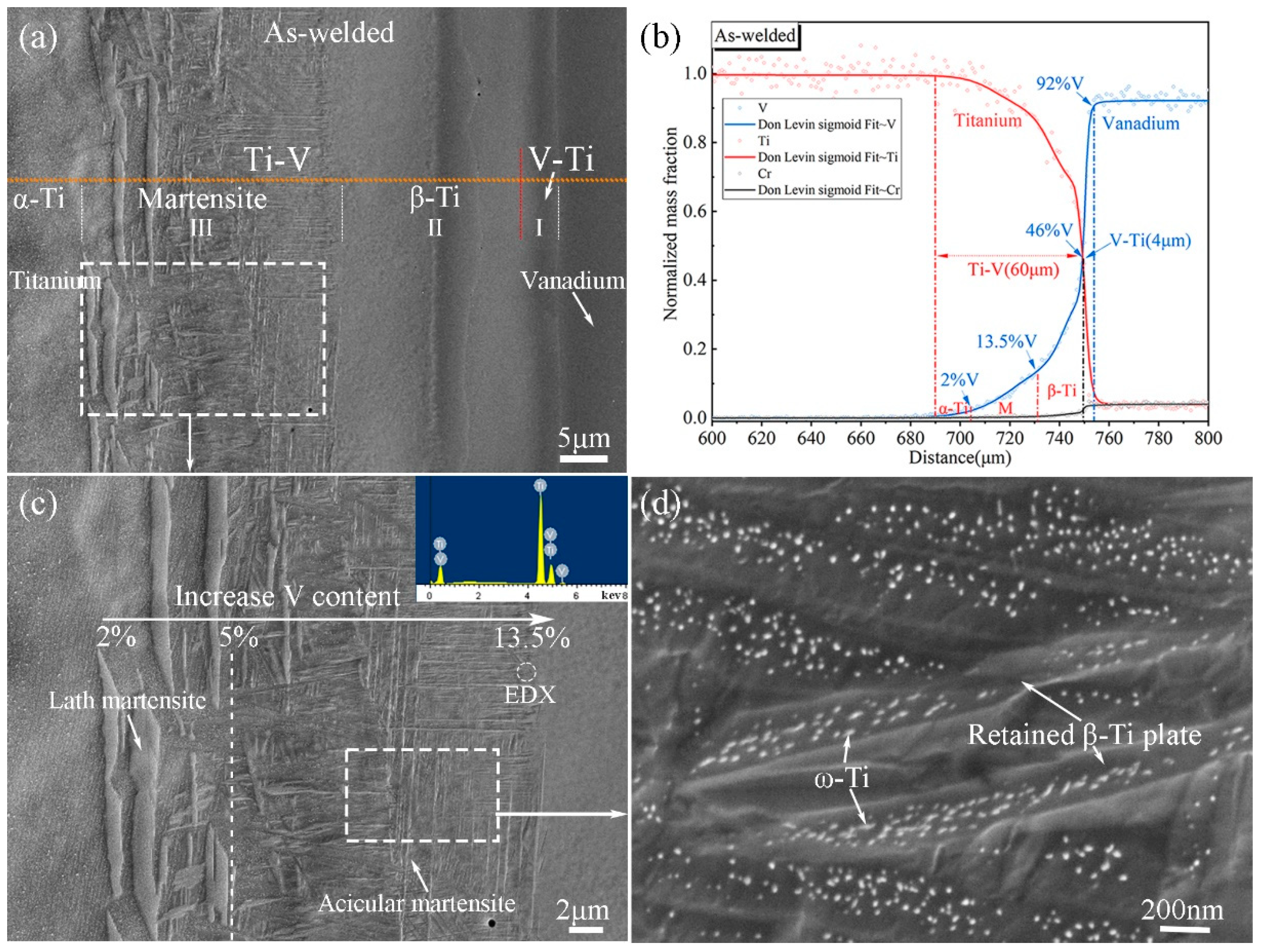
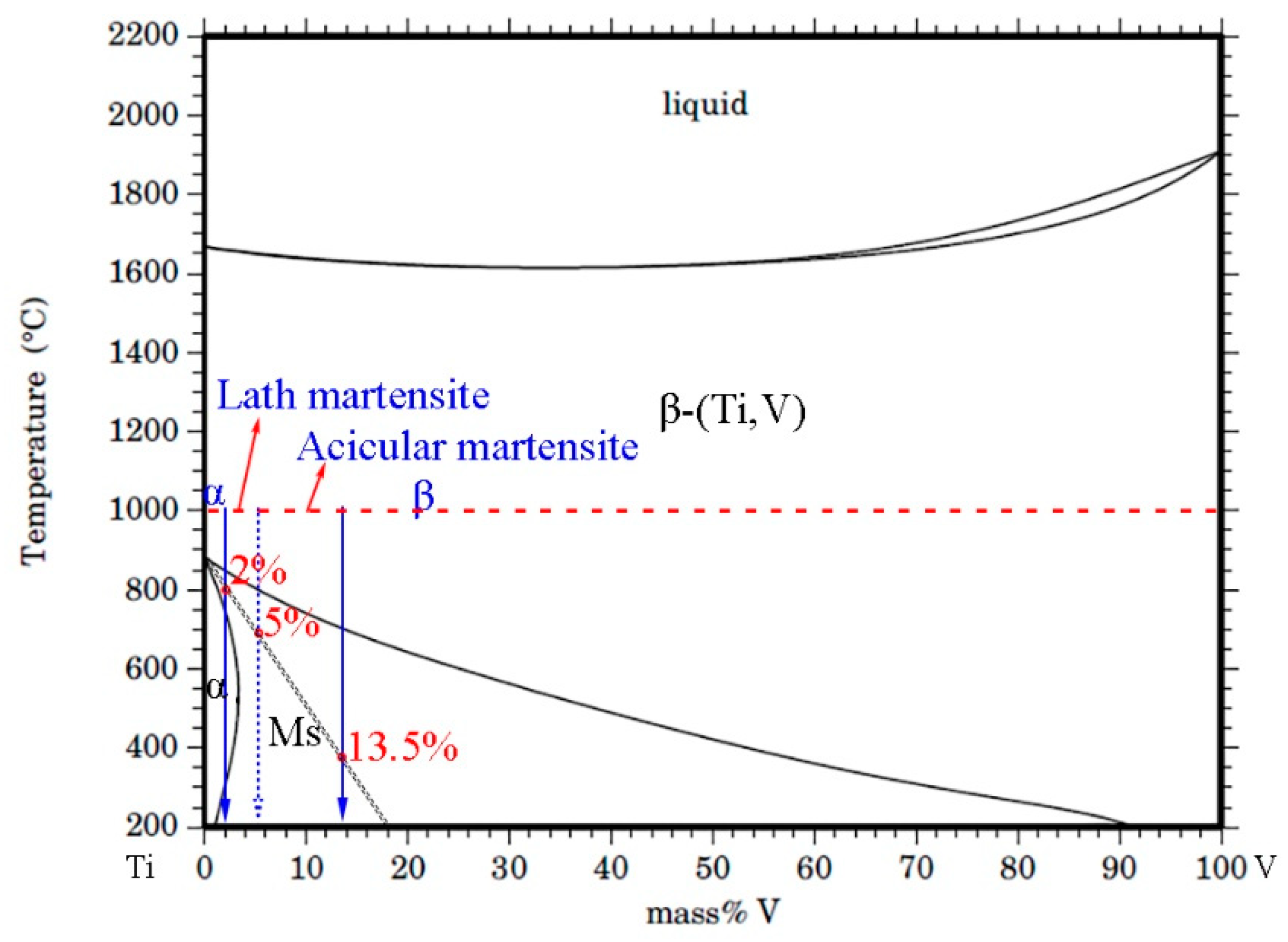
Ti–V interface bonding zones consist of a martensite Ti (α′-Ti) zone, a BCC structure Ti (β-Ti) zone, and a relatively small V–Ti alloy zone. They are divided by two composition interfaces (V ~13.5% and ~46%) and distinguished by contrasting EBSD data. The original interface falls within the β-Ti zone, as revealed by inert Y2O3 markers in the original V alloy substrate.
(2)
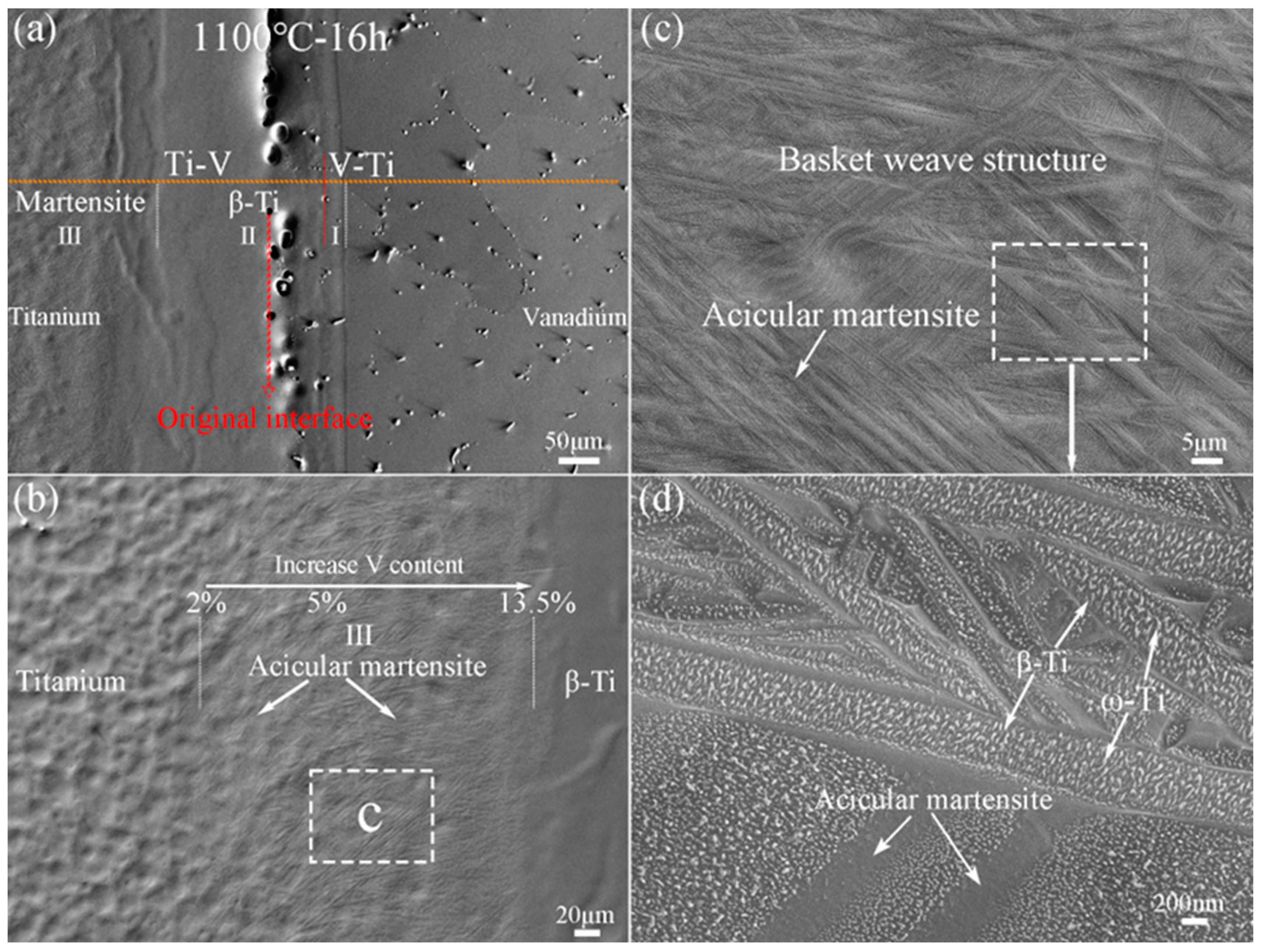
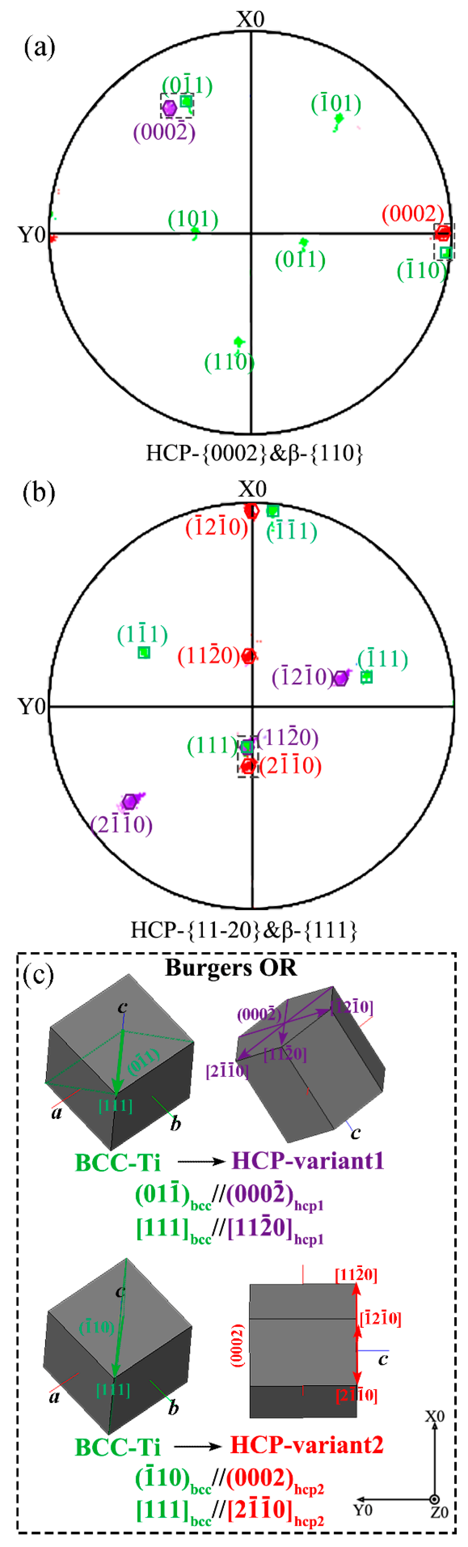
The Ti–V interface bonding zones exhibit two key microstructural evolution processes during rapid cooling. The first is the β→α′ martensite transformation, which is affected by accumulated strain energy generated by β-to-α phase transformation in the adjacent pure Ti. The ORs between martensite variants and β-Ti conform to Burger’s orientations relationship. The second is the recrystallization of β-Ti, which is affected by these two successive phase transformations. This is apparent from the appearance of deformed and recrystallized grains along the boundaries of the β-Ti grains.
(3)
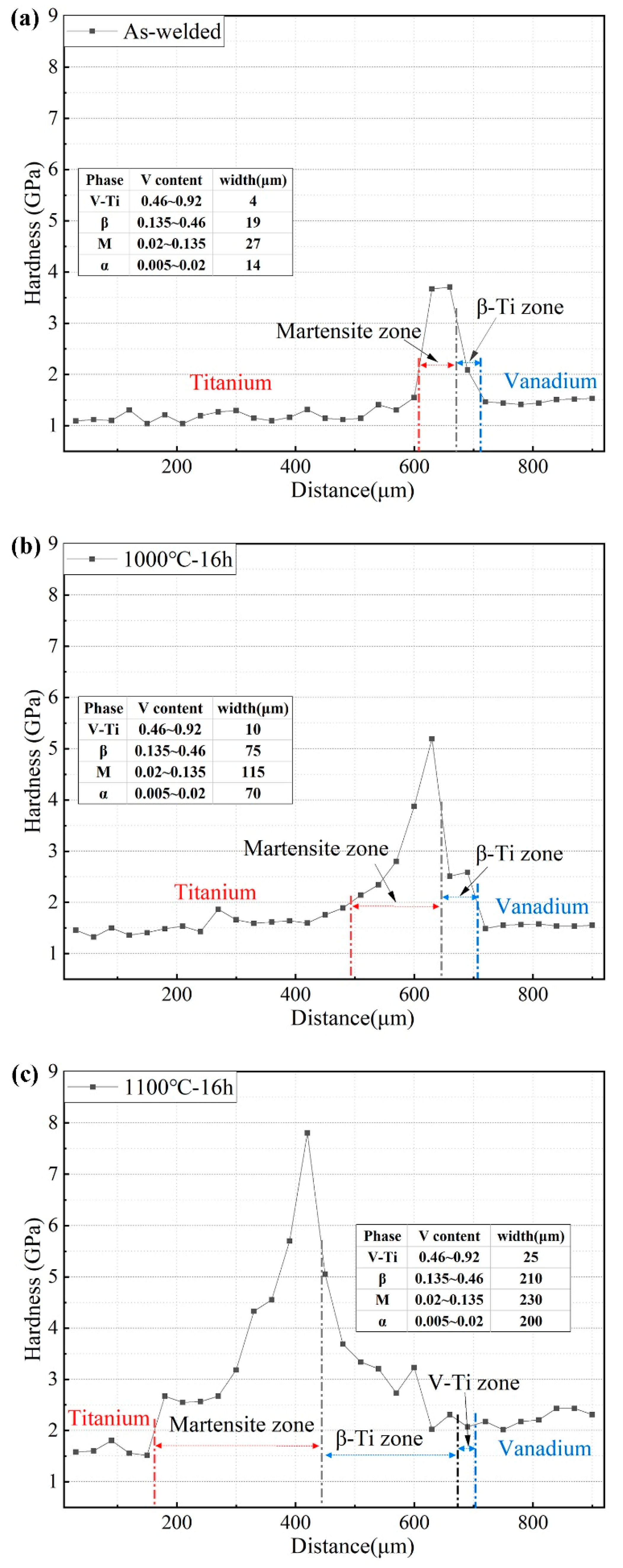
The hardness varies across the Ti–V interface bonding zones from pure Ti to V alloy. With increasing V content, the hardness of the martensite zone increases due to the increasing volume fraction of the hard ω-Ti phase. Upon further increasing the V content, the mechanical stability of the β-Ti increases and depresses stress-induced martensite transformation, which leads to decreased hardness in the β-Ti zone.

Author Contributions

Conceptualization, G.-L.L. and K.Z.; methodology, G.-L.L.; validation, M.-L.D. and G.-X.L.; formal analysis, M.-L.D. and Y.M.; resources, S.-W.Y.; writing—original draft preparation, G.-L.L.; writing—review and editing, K.Z. and D.-D.Q.; visualization, M.-L.D.; funding acquisition, K.Z. and D.-D.Q. All authors have read and agreed to the published version of the manuscript.

Funding

This research was funded by the National Natural Science Foundation of China, grant number 11802309.

Data Availability Statement

All the data are available within the manuscript.

Conflicts of Interest

The authors declare no conflict of interest.

References

  1. Banerjee, D.; Williams, J.C. Perspectives on Titanium Science and Technology. Acta Mater. 2013, 61, 844–879. [Google Scholar] [CrossRef]
  2. Kim, J.; Kim, M.; Knowles, J.; Choi, S.; Kang, H.; Park, S.; Park, S.M.; Kim, H.; Park, J.T.; Lee, J.; et al. Mechanophysical and biological properties of a3D-printed Titanium alloy for dental applications. Dental Mater. 2020, 36, 945–958. [Google Scholar] [CrossRef] [PubMed]
  3. Leyens, C.; Peters, M. Titanium and Titanium Alloys: Fundamentals and Applications; Wiley-VCH: Weinheim, Germany, 2003; pp. 333–350. [Google Scholar]
  4. Ding, J.; Yang, S.; Zhu, B.; Liu, H.; Liu, G.; Zhou, L.; Zhan, Q.; Wan, F. Twins induced by high-temperature ion irradiation in body-centered cubic V-4Cr-4Ti alloy. Scr. Mater. 2019, 162, 377–381. [Google Scholar] [CrossRef]
  5. Ding, J.; Yang, S.; Liu, G.; Li, Q.; Zhu, B.; Zhang, M.; Zhou, L.; Shang, C.; Zhan, Q.; Wan, F. Recrystallization nucleation in V-4Cr-4Ti alloy. J. Alloys Compd. 2019, 777, 663–672. [Google Scholar] [CrossRef]
  6. Jiang, N.; Zhou, F.; Zhang, G.; Yi, X.; Yu, C.; Wang, X.; Rao, W. Recent progress of vanadium-based alloys for fusion application. Tungsten 2021, 3, 382–392. [Google Scholar] [CrossRef]
  7. Zhang, G.; Han, W.; Yi, X.; Wan, F. Interface Characteristics of Ti-Clad V–4Cr–4Ti Alloy Diffusion-Bonded Joint Produced by Hot Forging. Appl. Sci. 2018, 8, 577. [Google Scholar] [CrossRef] [Green Version]
  8. Tomashchuk, I.; Grevey, D.; Sallamand, P. Dissimilar laser welding of AISI 316L stainless steel to Ti6–Al4–6V alloy via pure vanadium interlayer. Mater. Sci. Eng. A 2015, 622, 37–45. [Google Scholar] [CrossRef]
  9. Bobbio, L.; Bocklund, B.; Otis, R.; Borgonia, J.; Dillon, R.; Shapiro, A.; McEnerney, B.; Liu, Z.; Beese, A. Characterization of a functionally graded material of Ti-6Al-4V to 304L stainless steel with an intermediate V section. J. Alloys Compd. 2018, 742, 1031–1036. [Google Scholar] [CrossRef]
  10. Chen, J.; Muroga, T.; Qiu, S.; Nagasaka, T.; Huang, W.; Tu, M.; Chen, Y.; Xu, Y.; Xu, Z. The development of advanced vanadium alloys for fusion applications. J. Nucl. Mater. 2004, 329–333, 401–405. [Google Scholar] [CrossRef]
  11. Nagasaka, T.; Muroga, T.; Fukumoto, K.; Watanabe, H.; Grossbeck, M.; Chen, J. Development of fabrication technology for low activation vanadium alloys as fusion blanket structural materials. Nucl. Fusion 2006, 46, 618. [Google Scholar] [CrossRef]
  12. Chu, Q.; Zhang, M.; Li, J.; Yan, C.; Qin, Z. Influence of vanadium filler on the properties of Titanium and steel TIG welded joints. J. Mater. Process. Technol. 2017, 240, 293–304. [Google Scholar] [CrossRef] [Green Version]
  13. Li, R.; Zhang, Y.; Geng, D.; Zhang, G.; Hideo, W.; Han, W.; Wan, F. Characterization of interface irradiation damage in Ti-clad V-4Cr-4Ti composite material. Acta Phys. Sin. 2019, 68, 216101. [Google Scholar] [CrossRef]
  14. Banerjee, R.; Collins, P.; Bhattacharyya, D.; Banerjee, S.; Fraser, H. Microstructural evolution in laser deposited compositionally graded α/β titanium-vanadium alloys. Acta Mater. 2003, 51, 3277–3292. [Google Scholar] [CrossRef]
  15. Murray, J.L. The Ti–V (titanium-vanadium) system. Bull. Alloy. Phase Diagr. 1981, 2, 48–55. [Google Scholar] [CrossRef]
  16. Aurelio, G.; Guillermet, A.; Cuello, G.; Campo, J. Metastable Phases in the Ti-V System: Part I. Neutron Diffraction Study and Assessment of Structural Properties. Metall. Mater. Trans. A 2002, 33, 1307–1317. [Google Scholar] [CrossRef]
  17. Sluiter, M.; Turchi, P. Phase stability in Ti-V and Ti-Cr alloys: A theoretical investigation. Phys. Rev. B 1991, 43, 12251–12266. [Google Scholar] [CrossRef]
  18. Al Hazaa, A.; Haneklaus, N. Diffusion Bonding and Transient Liquid Phase (TLP) Bonding of Type 304 and 316 Austenitic Stainless Steel—A Review of Similar and Dissimilar Material Joints. Metals 2020, 10, 613. [Google Scholar] [CrossRef]
  19. Zoukel, A.; Khouchaf, L. The Secondary X-Ray Fluorescence and Absorption near the Interface of Multi-Material: Case of EDS Microanalysis. Micron 2014, 67, 81–89. [Google Scholar] [CrossRef]
  20. Banerjee, S.; Mukhopadhyay, P. Phase Transformations, Examples from Titanium and Zirconium Alloys; Elsevier: Oxford, UK; Britain, UK, 2007; p. 7. [Google Scholar]
  21. Oka, M.; Lee, C.; Shimizu, K. Transmission electron microscopy study of face-centered orthorhombic Martensite in Ti-12.6 Pct V alloy. Metall. Mater. Trans. B 1972, 3, 37–45. [Google Scholar] [CrossRef]
  22. Pelleg, J. Diffusion of 51Cr in V. Philos. Mag. A 1995, 71, 431–439. [Google Scholar] [CrossRef]
  23. Lutjering, G.; Williams, J.C. Titanium, 2nd ed.; Springer: Berlin/Heidelberg, Germany, 2007; p. 29. [Google Scholar]
  24. Ghosh, C.; Basu, J.; Ramachandran, D.; Mohandas, E. Phase separation and ω transformation in binary V-Ti and ternary V-Ti-Cr alloys. Acta Mater. 2016, 121, 310–324. [Google Scholar] [CrossRef]
  25. Humphreys, F.J. Characterisation of fine-scale microstructures by electron backscatter diffraction (EBSD). Scr. Mater. 2004, 51, 771–776. [Google Scholar] [CrossRef]
  26. Yang, J.; Xiao, S.; Chen, Y.; Xu, L.; Wang, X.; Zhang, D.; Li, M. Effects of nano-Y2O3 addition on the microstructure evolution and tensile properties of a near-α titanium alloy. Mater. Sci. Eng. A 2019, 761, 137977. [Google Scholar] [CrossRef]
  27. Bhattacharyya, D.; Viswanathan, G.B.; Fraser, H. Crystallographic and morphological relationships between β phase and the Widmanstatten and allotriomorphic α phase at special β grain boundaries in an α/β titanium alloy. Acta Mater. 2007, 55, 6765–6778. [Google Scholar] [CrossRef]
  28. Motyka, M. Martensite formation and decomposition during traditional and AM processing of two-phase titanium alloys—An overview. Metals 2021, 11, 481. [Google Scholar] [CrossRef]
  29. Cai, M.; Lee, C.; Lee, Y. Effect of grain size on tensile properties of fine-grained metastable β titanium alloys fabricated by stress-induced martensite and its reverse transformations. Scr. Mater. 2012, 66, 606–609. [Google Scholar] [CrossRef]
  30. Murdock, J.; Lundy, T.; Stansbury, E. Diffusion of Ti44 and V48 in titanium. Acta Metall. 1964, 12, 1033–1039. [Google Scholar] [CrossRef]
  31. Murdock, J.; McHargue, C.J. Self-diffusion in body-centered cubic titanium-vanadium alloys. Acta Metall. 1968, 16, 493–500. [Google Scholar] [CrossRef]
  32. Franke, P.; Seifert, H.J. Ternary Steel Systems: Phase Diagrams and Phase Transition Data, Binary System Ti–V. In Landolt-Börnstein—Group IV Physical Chemistry; Springer: Berlin/Heidelberg, Germany, 2012; Volume 19C1. [Google Scholar]
  33. Neelakantan, S.; Rivera-Díaz-del-Castillo, P.; Zwaag, V. Prediction of the martensite start temperature for β titanium alloys as a function of composition. Scr. Mater. 2009, 60, 611–614. [Google Scholar] [CrossRef]
  34. Collins, P.; Banerjee, R.; Banerjee, S. Laser deposition of compositionally graded titanium–vanadium and titanium–molybdenum alloys. Mat. Sci. Eng. A 2003, 352, 118–128. [Google Scholar] [CrossRef]
  35. Lee, S.; Lee, H.; Kim, J.; Chan, H.; Hong, J.; Yeom, J. Effect of prior β grain size on the martensitic transformation of titanium alloys. Mater. Charact. 2021, 182, 11525. [Google Scholar] [CrossRef]
  36. Liu, G.; Yang, S.; Han, W.; Yan, P.; Wang, M.; Hu, Q.; Misra, R.D.K.; Shang, C.; Wan, F. The simultaneous occurrence of Kurdjumov-Sachs and irrational orientation relationships between delta-ferrite and austenite phase in a 17Cr–5Ni stainless steel. Mater. Sci. Eng. A 2020, 798, 114112. [Google Scholar] [CrossRef]
  37. Van Bohemen, S.M.C.; Morsdorf, L. Predicting the Ms temperature of steels with a thermodynamic based model including the effect of the prior austenite grain size. Acta Mater. 2017, 125, 401–415. [Google Scholar] [CrossRef]
  38. Massalski, T.B. Massive transformations revisited. Metall. Trans. A 1984, 15, 421–425. [Google Scholar] [CrossRef]
  39. Zhou, X.; Liu, Y.; Yu, L.; Liu, C.; Sui, G.; Yang, J. Uniaxial diffusion bonding of CLAM/CLAM steels: Microstructure and mechanical performance. J. Nucl. Mater. 2015, 461, 301–307. [Google Scholar] [CrossRef]
Figure 1. SEM micrographs and corresponding EPMA composition curves for Ti–V diffusion interface zones: (a,b) as-welded; (c,d) 1000 °C for 16 h; (e,f) 1100 °C for 16 h. Scanning traces are marked as dotted yellow lines. The circles are the raw EPMA data, and the profile curves are the DLS fits.
Metals 12 02032 g001
Figure 2. SEM micrographs of as-welded Ti–V diffusion interface zones. (a) Magnified microstructure of Ti–V diffusion interface zones; (b) EPMA composition distribution; (c) enlarged micrograph of a martensite zone; (d) enlarged micrograph of acicular-martensite, displaying a mass of ω-Ti phase in the retained BCC structure β-Ti plate.
Metals 12 02032 g002
Figure 3. (a) SEM micrograph of Ti–V diffusion interface zones subjected to heat treatment at 1000 °C for 16 h; (b) magnified micrograph of acicular-martensite, showing the Widmanstatten microstructure; (c) enlarged micrograph of acicular-martensite.
Metals 12 02032 g003
Figure 4. (a) SEM micrograph of Ti–V diffusion interface zones after heat treatment at 1100 °C for 16 h; (b) SEM micrograph of a martensite zone; (c) enlarged micrograph of the basket-weave structure of acicular-martensite; (d) nano-sized ω-Ti phase in the acicular structure.
Metals 12 02032 g004
Figure 5. EBSD microstructure of Ti–V diffusion interface zones after heat treatment at 1000 °C for 16 h. (a) IPF map, (b) BC map, (c) SEM micrograph, (d) phase map (blue represents BCC phase, red represents HCP phase). (e) Recrystallization map (yellow represents sub-structured grain, blue represents recrystallized grain, and red represents deformed grain). (f) KAM map. (g) 3D crystallographic representations of four BCC structure grains shown in Figure 5a. Compositional distribution of Ti (h) and V (i). Black represents a noise point that could not be elucidated by EBSD. The step size for EBSD scanning was 0.5 μm.
Metals 12 02032 g005
Figure 6. Compound pole figures of (a) the {110} planes of β-Ti plus the {0002} planes of α′-Ti; (b) the {111} planes of β-Ti plus the {11–20} planes of α′-Ti. The parallel planes between β-Ti and α′-Ti are marked by a dotted box in the pole figures. (c) Three-dimensional crystallographic representations showing the orientation relationship between the two variants of the HCP structure α′-Ti and the BCC structure β-Ti. The β-Ti grain and two variants of α′-Ti correspond to β-Ti grain D and the differently colored lath-martensite in Figure 5a.
Metals 12 02032 g006
Figure 7. Nanoindentation hardness distribution across the Ti–V diffusion interface zones for different conditions. (a) As-welded; (b) 1000 °C for 16 h; (c) 1100 °C for 16 h. The V–Ti alloy zones in the as-welded and 1000 °C samples are too narrow to detect.
Metals 12 02032 g007
Figure 8. Ti–V binary phase diagram [32] with the calculated Ms of Ti martensite from Reference [33].
Metals 12 02032 g008
Figure 9. Schematic of lattice structure transformation in Ti–V diffusion interface zones during high-temperature diffusion and quenching process.
Metals 12 02032 g009
Publisher’s Note: MDPI stays neutral with regard to jurisdictional claims in published maps and institutional affiliations.

