Article

Development of Materials Based on the NiAlCrMoCo System Reinforced with ZrO2 Nanoparticles

1
Department of Nanotechnologies, Keldysh Research Center, 125438 Moscow, Russia
2
Department “Technology for the Production of Aircraft Engines”, Moscow Aviation Institute, National Research University, 125993 Moscow, Russia
*
Author to whom correspondence should be addressed.
Metals 2022, 12(12), 2014; https://doi.org/10.3390/met12122014
Submission received: 31 October 2022 / Revised: 17 November 2022 / Accepted: 21 November 2022 / Published: 24 November 2022
(This article belongs to the Special Issue High Energy Ball Milling and Consolidation of Nanocomposite Powders)

Abstract

:
This paper describes thermodynamic modeling of the NiAl–CrMoCo system with the calculation of the equilibrium composition and thermodynamic parameters of the system. NiAl-Cr-Mo-Co alloy samples of equiatomic composition, including those with a small addition of zirconium oxide nanoparticles, were obtained by spark plasma sintering of mechanically alloyed powders. It was found that the material had a two-phase structure with wedge-shaped regions enriched in cobalt and molybdenum with a gradient distribution. In addition, in the regions enriched with (Cr, Mo) phase, a lamellar σ phase was found. Fractographic analysis showed a positive effect of the fine-grained wedge-shaped regions on the damping of crack propagation. The alloy with the addition of zirconium oxide nanoparticles had a bending strength and an elastic modulus of 611 MPa and 295 GPa at 25 °C, and 604 MPa and 260 GPa at 750 °C, respectively, when tested in vacuum.

1. Introduction

Nickel–aluminum materials are promising for the manufacture of parts for power plants and engines serving various purposes, operating at high temperatures and in an aggressive medium. Compared to nickel alloys, the NiAl intermetallic compound with a B2 structure has a high melting point (1911 K) and low density (5.7 g/cm3), high heat resistance of up to 1273 K, and good thermal conductivity (70–80 W/(m·K) at 300–1400 K) [1,2,3,4]. However, nickel–aluminum is non-ductile and brittle at room temperature, although it has high strength properties and creep resistance at elevated temperatures [5]. There are ways to improve the material characteristics using additives of transition, rare-earth and noble metals [6,7,8,9,10,11,12]. Eutectic materials in the NiAl–CrMoCo system have high thermodynamic stability [13,14]. Molybdenum-based intermetallics have high thermal stability and combine good physical and mechanical properties. In addition, nickel–molybdenum alloys are resistant to radiation and high-temperature corrosion in molten salts. In addition, molybdenum forms hardening precipitates with transition metals in alloys [15,16].
Metallic materials modified with small additions of nanoparticles of refractory compounds insoluble in the matrix are characterized by high mechanical characteristics [17].
The addition of nanoparticles to the powder matrix promotes various positive strengthening effects:
reducing the grain size, preventing the boundaries from growing and moving, increasing the yield strength and tensile strength, maintaining the distance between them and stabilizing the acquired structure at the stage of cold pressing. This is an obstacle to the movement of the dislocation front, since they retain incoherence at the grain boundary [18,19,20,21];
contributing to strengthening by the mechanism of double grain boundaries [20,22];
inhibiting creep along the grain boundaries, pressing into the matrix and turning during crack spreading [19,23];
limiting the formation, and promoting the annihilation, of vacancies, increasing the creep resistance along the grain boundaries [24];
preventing the diffusion of oxidant molecules by adsorbing them on its surface [18].
In this work alloys of the NiAl–CrMoCo system, modified by small additions of nanoparticles, were synthesized by spark plasma sintering of a mixture of NiAl, Cr, Mo, Co powders. However, in order to understand the processes of phase formation, we present an analysis of the literature on the phase features of alloys similar in composition. A number of studies were analyzed to understand the phase transformations in alloys carried out on similar compositions [25,26,27,28,29,30,31,32,33,34,35,36,37,38,39,40,41,42,43,44,45,46,47,48,49,50,51,52,53,54,55,56,57,58,59,60]. For example, AlCoCrFeNi alloy powder was obtained by gas spraying in [26]. XRD analysis showed the presence of two phases: BBC and ordered BCC B2. Co was evenly distributed, Cr, Fe, Ni had small segregation, and Al had large segregation. Al–Ni-enriched areas were in the B2-phase, and Fe–Cr in BCC. The DSC curve had two exothermic peaks at 628 °C and 1376 °C, which corresponded to the formation of the FCC phase and melting, respectively [26]. The microstructure of the Al20Co20Cr20Fe20Ni20, Al10Co30Cr20Fe35Ni5 and Al15Co30Cr15Fe40Ni5 HEAs consisted of fine grains with sizes in the range of 50–500 nm, composed of AlNi–B2, BCC phase, FCC or BCC solid solutions and σ-sigma phase, respectively.
According to DTA data, the hunched area from 600 °C to 780 °C could be associated with the dissolution of the FCC-L12 phase, which was stable up to 500–620 °C, according to [27]. The peak at 1000 °C corresponded to the complete dissolution of the σ-phase. Chromium in the σ-phase was redistributed between the disordered solid solutions of the FCC–A1 and/or BCC–A2 phases. An alloy with a high aluminum content (Al15CoCrFeNi) did not have a dissolution peak of the σ-phase. The peak from 1200 °C to 1400 °C corresponded to the dissolution of the BCC and FCC solid solution, as well as early melting, when the solid solutions were in equilibrium with the liquid in [28]. Endothermic peaks from 1480 °C most likely corresponded to early phase melting.
The high-entropy alloy (HEA) CoCrFeMo0.85Ni, studied by the authors during thermal analysis, had peaks at 1323 °C and 1331 °C, which corresponded to the solidus and liquidus temperatures, as well as at 800 °C and 1212 °C, which corresponded to the phase transitions FCC + μ + σ → FCC + σ → FCC [29].
In work [25] NiAl–13Cr–13Mo (wt.%) material was formed by spark plasma sintering. The main phases were NiAl–B2 and (Cr, Mo), and intermetallic compounds of the Al–Mo system. Cast alloys of the NiAl–Cr–Mo system in various compositions contained Cr–BCC, NiAl–B2, AlMo3, MoNi, and oxide phases [30]. According to the work on modeling the Cr–Mo–Co diagram at 1373–1573 K in [31], the system contained the FCC, BCC, HCP, R, σ and μ phases.
HEA materials with similar composition with the material that was studied in this work also contained the following phases: Cr23C6–D84 [32,33], σ-CoCr [34], AlNi–B2 [29], Cr7C3 [35], σ–Co2Mo3 [36], Cr(Co)e, Cr(Co,Mo) [37], and γ–Co (Ni) [38,39]. It should be noted that alloying elements that are added to NiAl-based materials are divided into three groups: Group VIII elements (Fe, Co, etc.); Cr, Mo, W, Re, V; elements of IIIB, IVB and VB subgroups. Iron and cobalt are highly soluble in the NiAl matrix and increase strength and ductility. Cr and Mo form pseudobinary eutectic phases, and increase fracture toughness and creep resistance [40,41]. A high content of Mo leads to embrittlement of the material, due to the formation of a hard phase of the sigma type. However, the presence of such a compound can increase the wear resistance of the material. Depending on the concentration, cobalt provides hardening, due to the formation of a continuous solid solution with NiAl and isostructural compounds. Alloys of the Ni–Al–Co system usually consist of several phases: β–NiAl, γ–Co(Ni) and γ’–Ni3Al [21].
It is well known that σ, μ and other topologically close-packed (TCP) phases, separating in the form of plates (tapes), sharply reduce load resistance and plasticity at high temperatures. The atomic radii of the metals forming the σ phase differ slightly (no more than 8, less often 10–12%) from each other. However, the difference in the atomic radii of the elements that form the μ phase is quite large. They can exist as a single σ phase or decompose into a tetragonal σ phase, a rhombohedral μ phase, an orthorhombic ρ phase, and others, depending on the composition and atomic radius of the elements. These phases separate from the solid solution and are distinguished by an increased content of Cr, Mo, etc. compared to the alloy. These phases in multicomponent systems are electron compounds, because their structure is determined by the electron concentration e/a. This is the ratio of the number of valence electrons (e) to the number of atoms in a unit cell (a). In TCP phases, some atoms have electropositive properties (Cr, Mo), and others have electronegative (Ni, Co, Fe) properties. The tendency of the alloy to form TCP phases depends on the level of alloying and the concentration of elements. The microstructure of the σ-phase is close to the M23C6 structure in nickel alloys. If all carbon atoms are removed from the M23C6 lattice, then a very small shift in the mutual bracing of atoms would lead to the formation of the σ-phase. This is significant, because Cr21Mo2C6 carbide contains many Cr and Mo atoms necessary for the formation of the σ phase. The same scheme is applicable to the formation of the μ-phase. Structurally, the μ phase is close to M6C. In alloys containing M6C and an excess of Cr and Mo, it is logical to expect a μ phase, instead of σ [42].
In [21], the formation of complex phases in the NiAl–15Mo–12Cr–6Co alloy of the Cr-based solid solution type Cr (Co, Ni, Al) residing between NiAl grains was established. In addition, Cr0.8Mo0.2 or Cr0.5(Mo, Ni, Co)0.5 solid solution phases were found in an alloy with Mo content up to 2.5% wt. According to [43], in the NiAl–14Co alloy, the main phases that appeared in the XRD pattern were γ’–Ni3Al, β–NiAl, and NiAl–martensite. In [21], in the NiAl–Cr–Co–15Mo material, the main phases identified by XRD analysis were: NiAl, complex carbide (Ni, Cr, Co)3Mo3C, Ni3Al, chromium-based solid solution, molybdenum-based solid solution.
In [44], an alloy. Co–Cr–Ni–Mo with an equiatomic ratio of the components, was studied. The main phases were σ, eutectic FCC, and eutectic σ. The study in [45] was devoted to a high-entropy alloy of the system (CoCrFeNi)100xMox (x = 1 − 3) and showed that the material consisted of FCC and σ phase.
In [46], new eutectic high-entropy alloys based on novel (CoqCrvFewMoyNiz)100xAlx alloys contained FCC and B2 phases.
In [47], the chemical compositions of the CoCrFeNiMox (x = 0, 0.1, 0.11, 0.18, 0.2, 0.23 and 0.3, corresponding to 0, 2.44, 2.68, 4.31, 4.76, 5.44 and 6.96 at.%) alloy system were studied. It was found that with an increase in the amount of molybdenum, in addition to the FCC phase, σ and μ phases were detected.
In nickel superalloys, as a rule, TCP phases worsen ductility. However, it was reported in [23,47,48] that high-entropy alloys of the CoCrFeNiMo system had a good combination of strength and ductility after heat treatment, due to the formation of TCP σ and μ phases. In addition, an increase in the amount of Mo led to the formation of intermetallic compounds and deformation of the crystalline lattice of the alloy, which reduced the mobility of dislocations, leading to an increase in the strength of the alloy [49]. The authors of work [23] reported that the σ-phase was found to be a (Cr,Mo)-rich phase, corresponding to stoichiometric (Cr,Mo)(Co,Fe,Ni) composition, and the μ-phase was found to be a (Mo,Cr)-rich phase, corresponding to stoichiometric (Mo,Cr)7(Co,Fe,Ni)6. The solid–solution strengthening of the face-centered cubic matrix and the formation of the σ or σ + μ phases were the two main reasons for the strengthening of the alloy.
Table 1 shows the phase compositions and mechanical properties of alloys similar to the studied systems. As can be seen, an excess of nickel or cobalt promotes the formation of the FCC phase. An excess of chromium and molybdenum leads to the formation of TCP phases and BCC phases.
In areas enriched in aluminum, cobalt and nickel, three-phase alloys based on B2-CoAl intermetallic compound in the Co–Al–Ni system were formed [60]. B2 phase formed a continuous solid solution with NiAl of the same structure. Combination with B2 phase could result in a (Co,Ni) solid solution continuous from Co to Ni (phase diagram angles) and/or L12 phase, based on Ni3Al. The L12 phase could be designated as (Ni,Co)3Al. Ni served as a stabilizer of the FCC structure and prevented the cobalt FCC → HCP phase transition. Usually, ternary alloys with 0–35 at. % Ni had a B2 single-phase microstructure. As the amount of nickel increased towards the NiAl L12 angle, the phase began to form a second phase in the (Co,Ni) in the B2 matrix. In addition, it was found that aging an alloy with 21 at. % Ni at 1373 K for an hour led to the separation of lamellar phases of the solid solution (Co,Ni) in the B2 matrix [60].
The main objectives of this work were to obtain a material based on the NiAl–CrMoCo system with an equiatomic ratio of elementary components and to study the effect of a small amount of zirconium oxide nanoparticles on the structure and properties of the resulting material.

2. Materials and Methods

Alloys of the NiAl–CrMoCo system were synthesized by spark plasma sintering. The powders were mixed in steel containers with steel grinding media in a vibratory ball mill ‘MML’ (LLC “Vibrotekhnika”, Moscow, Russia). Powders of NiAl, as well as elemental Mo, Cr, and Co, in equiatomic concentrations, were mixed to obtain composite compositions.
The technology for nickel composites manufacturing included the preparation and mixing of initial powders (NiAl, PN70Yu30), JSC “Polema” (Tula, Russia)), Cr (98.5%, 150 µm, PH1S), JSC “Polema” (Tula, Russia)), Mo (99.5%, 5 µm, MPCh, LLC “Atomspecsplav”, St. Petersburg, Russia), Co (99.9%, 1 µm, OCHV (Moscow, Russia)), ZrO2–8Y2O3 nanoparticles (Keldysh Research Center, Moscow, Russia) with specific surface area—25 m2/g. The appearance of powders was described in detail in [25]. Figure 1 shows the microstructure of the mixture of powders, obtained after vibromilling.
Mechanical alloying of the metal powders mixture was carried out in an Activator-2SL planetary mill (LLC «Zavod Himicheskogo Mashinostroeniya», Dorogino, Russia) in vacuum steel jars. Grinding balls (LLC «Zavod Himicheskogo Mashinostroeniya», Dorogino, Russia) made of stainless steel with a diameter of 5 mm were used. The ratio of powder to balls was equal to 1:10. Activation was carried out in isopropyl alcohol of chemical purity with the addition of a surface-active agent. Cubic zirconia nanoparticles were dispersed in isopropyl alcohol using a UPS 3600 Bandeline (BANDELIN electronic GmbH & Co. KG, Berlin, Germany) ultrasonic homogenizer for 3 min at a power level of 50% in pulsed mode. Nanoparticles were added to the matrix powder in isopropyl alcohol under low power ultrasound in an ultrasonic bath for 5 min, while stirring the solution with an overhead stirrer Eurostar digital (IKA®-Werke GmbH & Co. KG, Staufen, Germany) at a speed of 400 rpm. Then, drying was carried out in a vacuum oven (Stegler, Moscow, Russia) at 250 °C for 10 h. After that, the powder was sintered by the spark plasma method on the FCT Systeme Gmbh machine (FCT Systeme Gmbh, Rauenstein, Germany) in the form of cylinders with a diameter of 30 mm and a height of 3 mm. The sintering was carried out at 1150 °C for 20 min in argon with the pressure 50 MPa. Samples with nanoparticle concentrations 0.01 wt.% and without nanoparticles were obtained.
The morphology and composition of the materials were studied by scanning electron microscope (SEM) Quanta 600 (FEI Company, Hillsboro, OR, USA) with TRIDENT XM4 energy-dispersive X-ray spectroscopy (EDX) equipment (). X-ray phase analysis (XRD) was performed in β-filtered cobalt radiation by a horizontal 2θ-θ X-ray diffractometer HZG-4 (LLC EDAX, Warrendale, USA). The phases were identified using the ICDD PDF-2 database (release 2003). The ultimate bending strength was determined by the three-point method on a Test Systems-VacEto universal mechanical testing machine (Keldysh Research Center, VacEto LLC, Moscow, Russia). The microhardness of the samples was determined by the Vickers method on a TM-40 hardness tester (Ultrakon, Kiev, Ukraine). Young’s modulus was measured by the ultrasonic method on the MUZA® device (Vac-Eto, Moscow, Russia).
The NiAl–Mo–Cr–Co matrix powder sample was studied by differential scanning calorimetry (DSC), thermal gravimetric and differential thermal gravimetric analyses (DTG and TG) on a NETZSCH STA449F 1 Jupiter thermal analyzer (Netzsch-Gerätbau, Selb, Germany) in a corundum crucible in the temperature range from 25 °C to 1550 °C at a heating rate of 10°/min in an argon atmosphere.
Thermodynamic modeling of the system, namely the change in composition at temperature range 600–1200 °C, was carried out in the Terra® software (v. 6.2 by Bauman Moscow State Technical University, Moscow, Russia). The method and algorithm for calculating the composition of phases in complex multi-element systems implemented in the Terra® program performs a series of calculations with a variation in temperature and content of initial substances. Multiple calculations in a given temperature range for all possible ratios of the initial substances make it possible to find areas with the same sets of one-component condensed phases. Such calculations provide information that can limit the range of parameters for furthermore detailed studies or the assignment of technological conditions for the processes.

3. Results

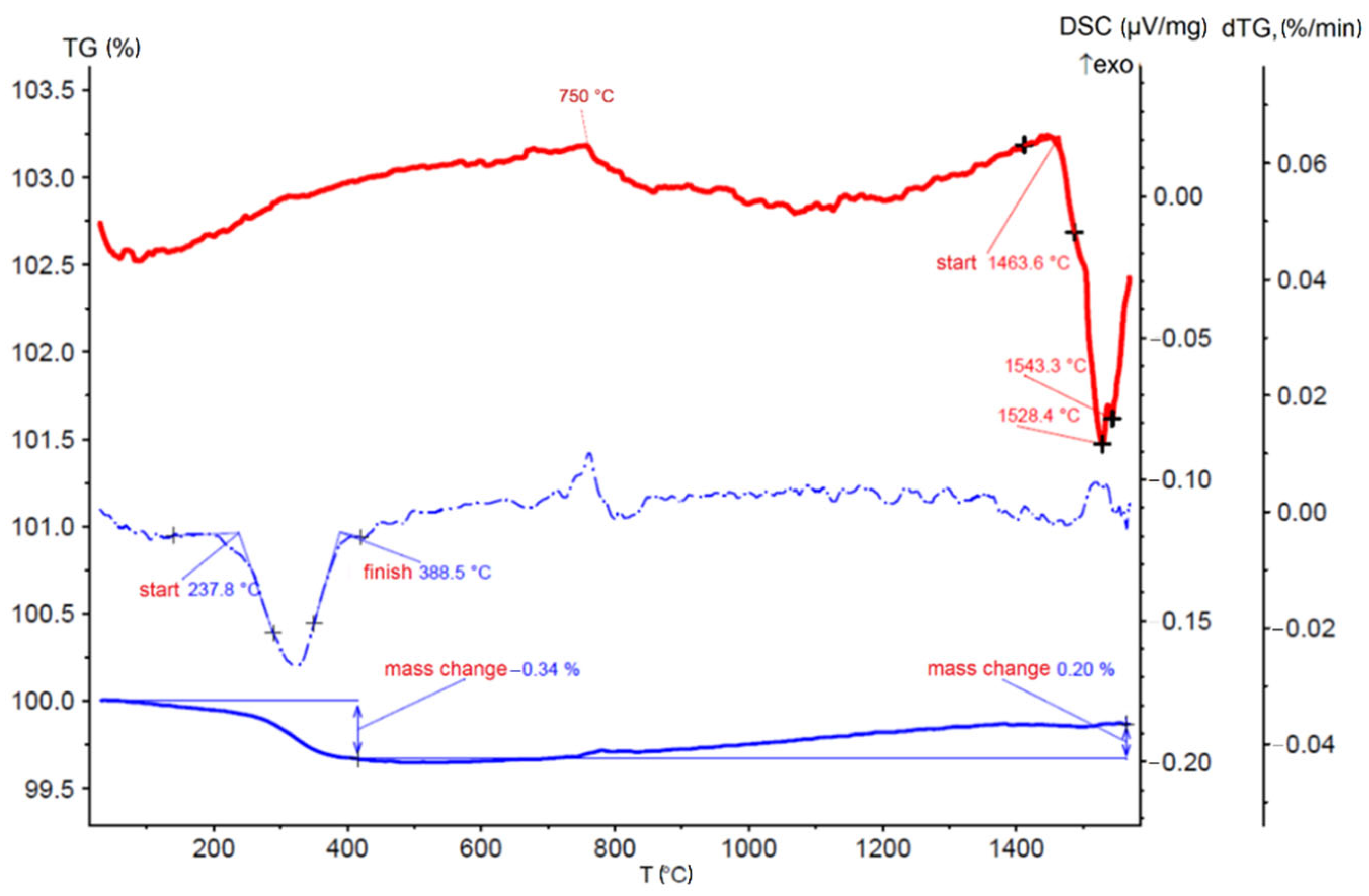
3.1. Thermal Analysis

The results of DSC, TGA and TG the NiAl-Cr-Mo-Co matrix powder analyses are shown in Figure 2. In the temperature range from 240 °C to 390 °C, an insignificant weight loss of 0.34% occurred, while there were no peaks on DSC. The mass from 390 °C to the final heating temperature slightly increased by 0.2%. The peak in the region of 700–750 °C might correspond to the formation of the FCC phase. Starting from a temperature of 1464 °C, the DSC curve showed a several-stage overlapping endothermic process with observed peaks at temperatures of 1528 °C and 1543 °C, associated with the melting of various phases. There was nearly no overall weight change (slight loss of 0.14%).

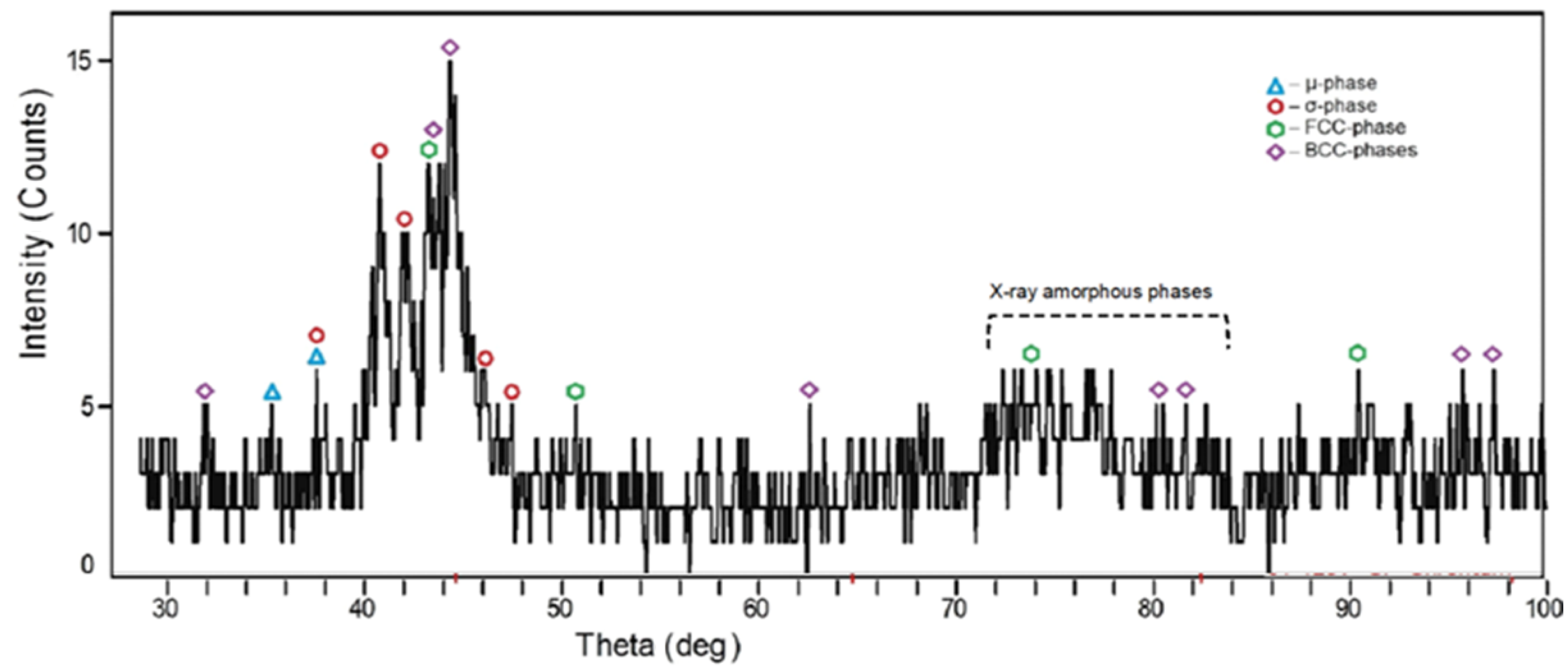
3.2. Phase Composition

Figure 3 shows the result of X-ray phase analysis of a sample of the NiAl–CrMoCo matrix. It could be concluded that there were reflections of solid solutions of a complex composition with a different type of structure, similar to materials described in [16,29,36]. In addition, peaks of TCP phases (most likely, σ and μ), based on the Co–Mo system were visible and there was a halo of X-ray amorphous phases with all of the main elements.

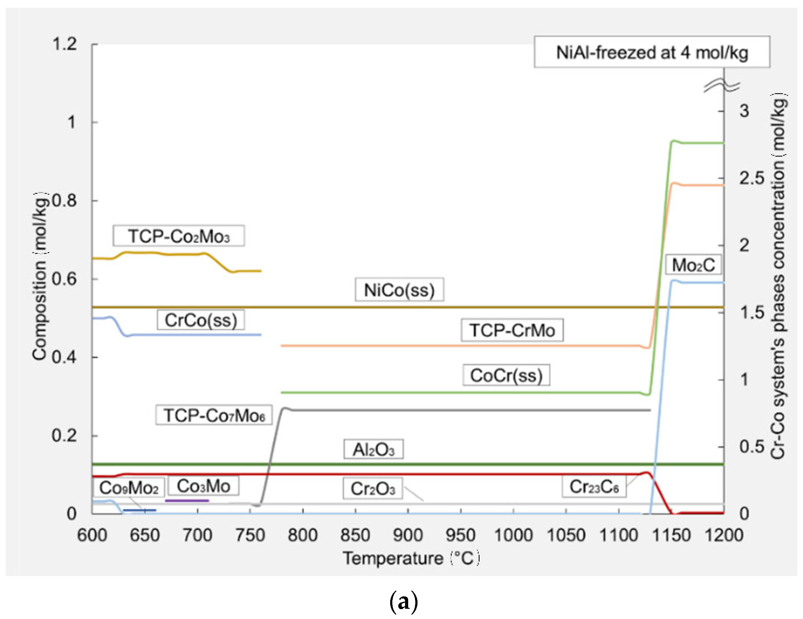
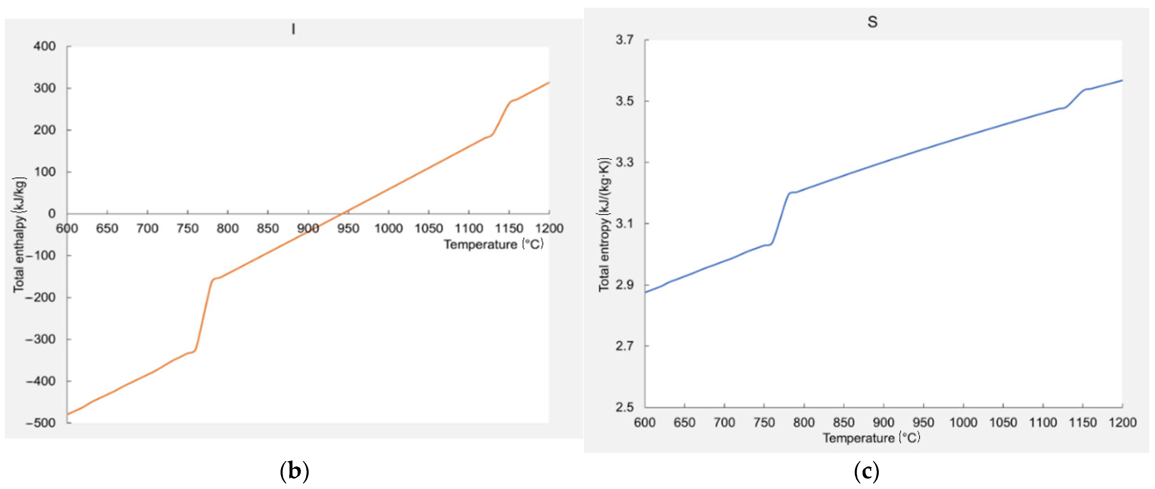
3.3. Thermodynamic Modeling

The complexity of predicting the composition of multicomponent alloys containing an equiatomic number of elements lay in the development of many physicochemical processes, including competing ones, associated with selective dissolution, segregation of impurities, etc. In addition, the task was complicated by the fact that the samples were obtained under nonisothermal conditions of rapid heating and cooling, which were created during spark plasma sintering.
Thermodynamic modeling was carried out using the Terra® software package for predicting phase evolution in new alloys [25]. In this work it was used to calculate the equilibrium composition of the NiAl–Cr–Mo–Co system. Data on the enthalpy of formation and heat capacity of a number of intermetallic compounds and various phases were taken from a number of verified sources [61,62,63,64,65,66,67,68,69,70,71,72,73,74,75,76,77,78,79,80,81].
The standard entropy, standard enthalpy, coefficients for the heat capacity polynomial were calculated according to known methods [82,83,84,85,86,87,88]. According to the recommendations of [83], one of the ways to estimate the value of the increment H 298 0 H 0 0 is to use the equation:
H 298 0 H 0 0 = 0.5 × c p , 298 0 298.15
The equation for the temperature dependence of the crystalline substances heat capacity in the range from 298 K to the melting temperature according to Mayer–Kelly was used in this work [89]:
Cp = a + 0.001 × b × T + 105 × c × T−2
The heat capacity of intermetallic compounds of the AxBy type was calculated using the Neumann–Kopp method [90]:
Cp(AxBy) = xCp(A) + yCp(B)
Often the equation Cp = f(T) = a + bT for temperatures above 298 K is used to describe the temperature dependence of heat capacity. It quite rightly describes the change in the isobaric heat capacity not only of simple substances, but also of many compounds according to Perry and Green reference book [91].
The equation of standard heat capacity calculation is:
c p , 298 0 = i m i c p , 298 0 i ,   J / ( mol · K ) ,
where c p , 298 0 i is the standard heat capacity of the i-th simple substance, i m i is sum of moles of simple substances in solution,
The equation of standard entropy of intermetallic compound calculation is:
S 298 0 A x B y = x S 298 0 A + y S 298 0 B
Terra® software was previously successfully used to describe various multicomponent systems of alloys and composite materials, including those containing transition metals and non-metallic inclusions [25,92,93]. A feature of the methodology used in calculating the compositions of systems in the Terra software is that it is based on the principle of maximum entropy for an isolated equilibrium system, in contrast to the use of the concept of Gibbs energy, equilibrium constants and the principle of Guldberg and Waage of interacting masses [94].
The following assumptions are considered when using the methodology incorporated in the Terra® software [95]:
closed and isolated thermodynamic systems are considered, where the boundaries are impenetrable for the exchange of matter, heat and energy with the environment;
systems are analyzed in a state of external and internal thermodynamic equilibrium (full or local);
it is considered that the system is heterogeneous, consisting of several homogeneous parts (phases) separated by visible boundaries;
the presence of the gas phase in the system is mandatory;
all gaseous individual substances (atoms, molecules, atomic and molecular ions, electron gas) are part of one gas phase;
the gas phase is described by the equation of state of an ideal gas;
surface effects at the phase boundary are not considered, the solubility of gases in condensed (liquid and solid) phases is absent; condensed matter may be absent;
condensed substances forming one-component immiscible phases are included in ideal condensed solutions;
individual substances that have the same chemical formula, but are included in different phases, are considered to be different components;
substances with the same chemical formula, which are in various polymorphic modifications, crystalline or liquid states, are considered as one component, in which the change in properties occurs abruptly at transformation temperatures;
the volume of condensed components is negligible.
The equilibrium of such systems, in accordance with the second law of thermodynamics, is characterized by a maximum of entropy relative to the thermodynamic degrees of freedom, which include the concentrations of the components of the equilibrium mixture (n, mol/kg), temperature T and pressure P.
S = i = 1 K S i 0 T R 0 ln R 0 T V n i × n i + c = 1 R S c 0 T n c + N m = 1 N m S m 0 T R 0 ln n m n N m × n m S m a x
where ni, nc, nm, Si0, Sc0, Sm0 are the number of moles and the standard entropy at temperature T and pressure 0.1 MPa in gas (i), condensed (c) phases and in solution (m), respectively; i, c, m—the number of gaseous, condensed components and solutions in the thermodynamic system, respectively. The value n N m is the amount of substance in the m-th condensed solution; V—volume; Ri—the gas constant.
The specific volume V, as well as the internal energy U, remain independent variables, since the equilibrium conditions of the system, relative to the environment, can be expressed using the equalities:
dV = 0 and dU = 0 or V = const and U = const
Calculations of the equilibrium composition of the material in the temperature range of 873–1473 K at a pressure of 0.01 MPa showed that, in addition to solid solutions with the FCC and BCC structure from the main elements, intermetallic phases and TCP phases could form in the system. This approach to the calculation was adopted to consider the processes occurring under nonequilibrium conditions during SPS sintering of mechanically activated components. The impurity concentrations of C and O were considered in the calculations. Thermodynamic calculations determine the stability of certain phases in alloys with wide and narrow regions of homogeneity, including those accompanied by the formation of intermetallic compounds.
Since many intermetallic alloys and phases of transition metal solutions for which thermodynamic parameters are calculated were first considered using the Terra® program, below we present the values of the polynomial coefficients for the reduced Gibbs energy of these substances, calculated according to the algorithms given in [95], in Table 2 and Table 3.
Figure 4a shows the results of thermodynamic modeling for the interaction of components of the following composition, mole: (NiAl − 0.6) + (Cr − 0.3) + (Mo − 0.3) + (Co − 0.3) + (C − 0.01) + (O − 0.01) at 4 mol/kg constant concentration of the NiAl. The constancy was due to the fact that the main (“first”) stable phase in the material was precisely NiAl or a solution based on it with a small quantity of dissolved substances. The “second” phase was formed by alloying elements, the transformations of which, and the interaction with the “first” phase, affected its final composition. According to the results of thermodynamic modeling at a temperature near the sintering point (1170 °C), the main phases were BCC–CoCr(ss) and FCC–NiCo(ss) solid solutions, in addition to the “frozen” NiAl, as well as the close-packed TCP–CrMo. The molybdenum carbide Mo2C content increased, and the amount of carbide (Cr23C6) decreased with temperature increasing. Aluminum and chromium oxides were also present. In work [22] pseudobinary diagram (Co, Cr, Fe, Ni)–Mox was simulated at 600–1500 °C. According to this work, with an increase in the amount of molybdenum (x) from 0.5 to 1 in the system, in the range from 600 °C to 1070 °C, there were three phases, FCC + μ + σ. In materials, aluminum and chromium oxides appeared, due to the presence of oxide layers on metal powder surfaces. Chromium and molybdenum are good carbide formers, so when graphite molds are used in spark plasma sintering, diffusing carbon atoms actively interact with these metals.
Figure 4b, c also shows the change in the total enthalpy and entropy of the calculated system. Both ascending curves had two inflections each, which corresponded to phase transitions. In particular, the first inflection was in the range 750–775 K, and the second inflection was in the range of 1125–1150 K. The first inflection corresponded to the appearance of TCP phases. The second one corresponded to an increase in one of the earlier appearing TCP phase concentration and amount of solid solution and molybdenum carbide.

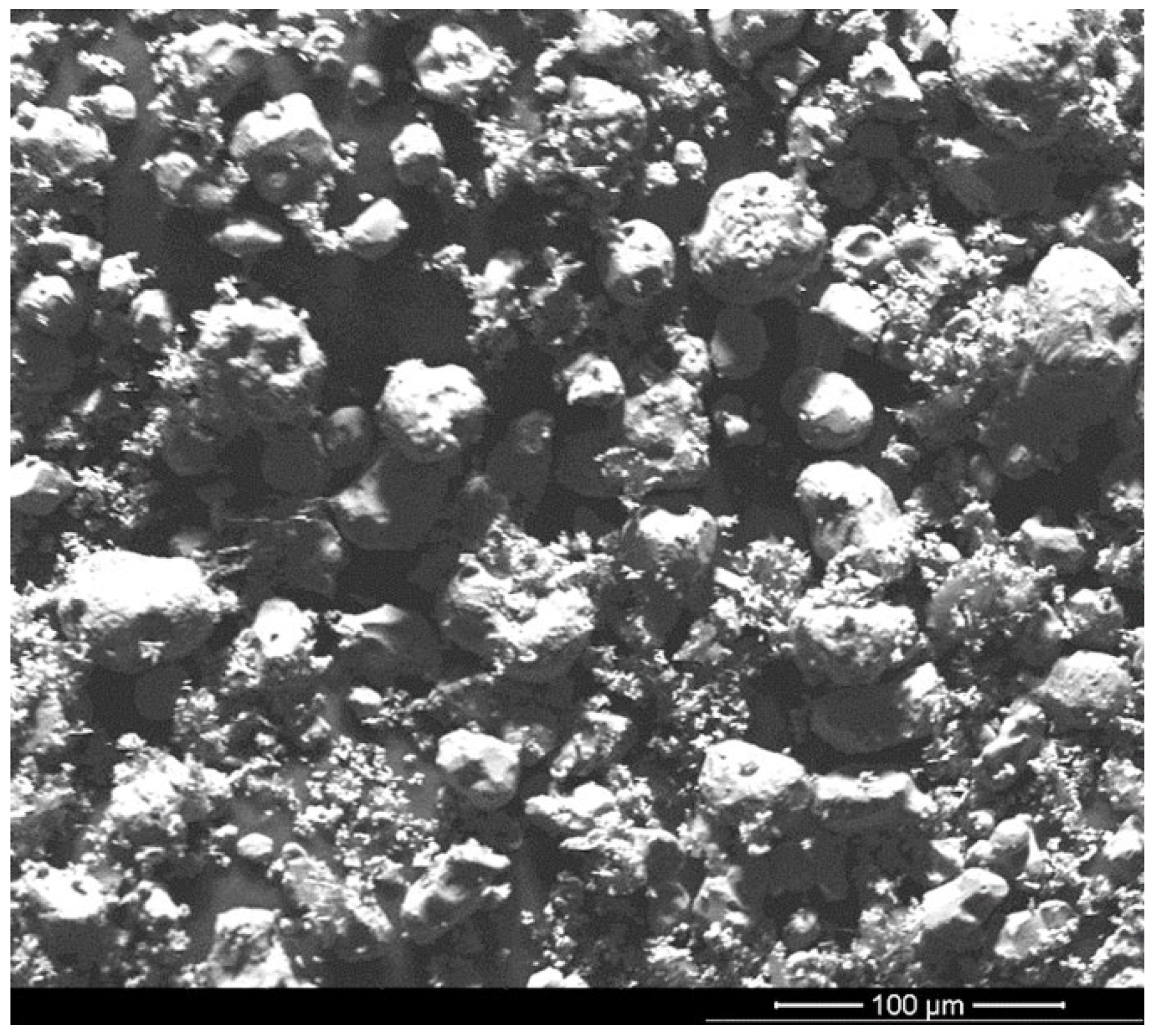
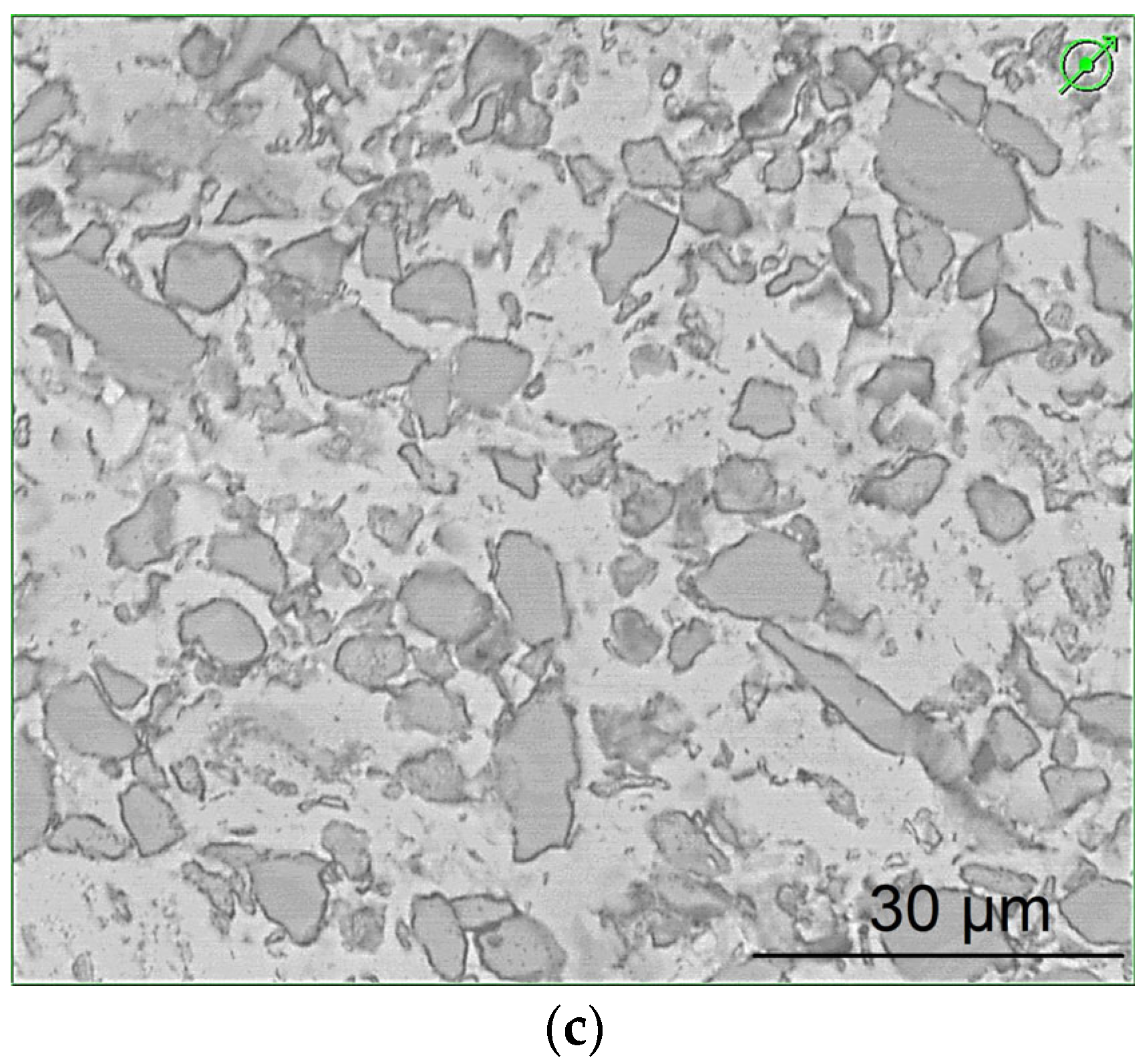
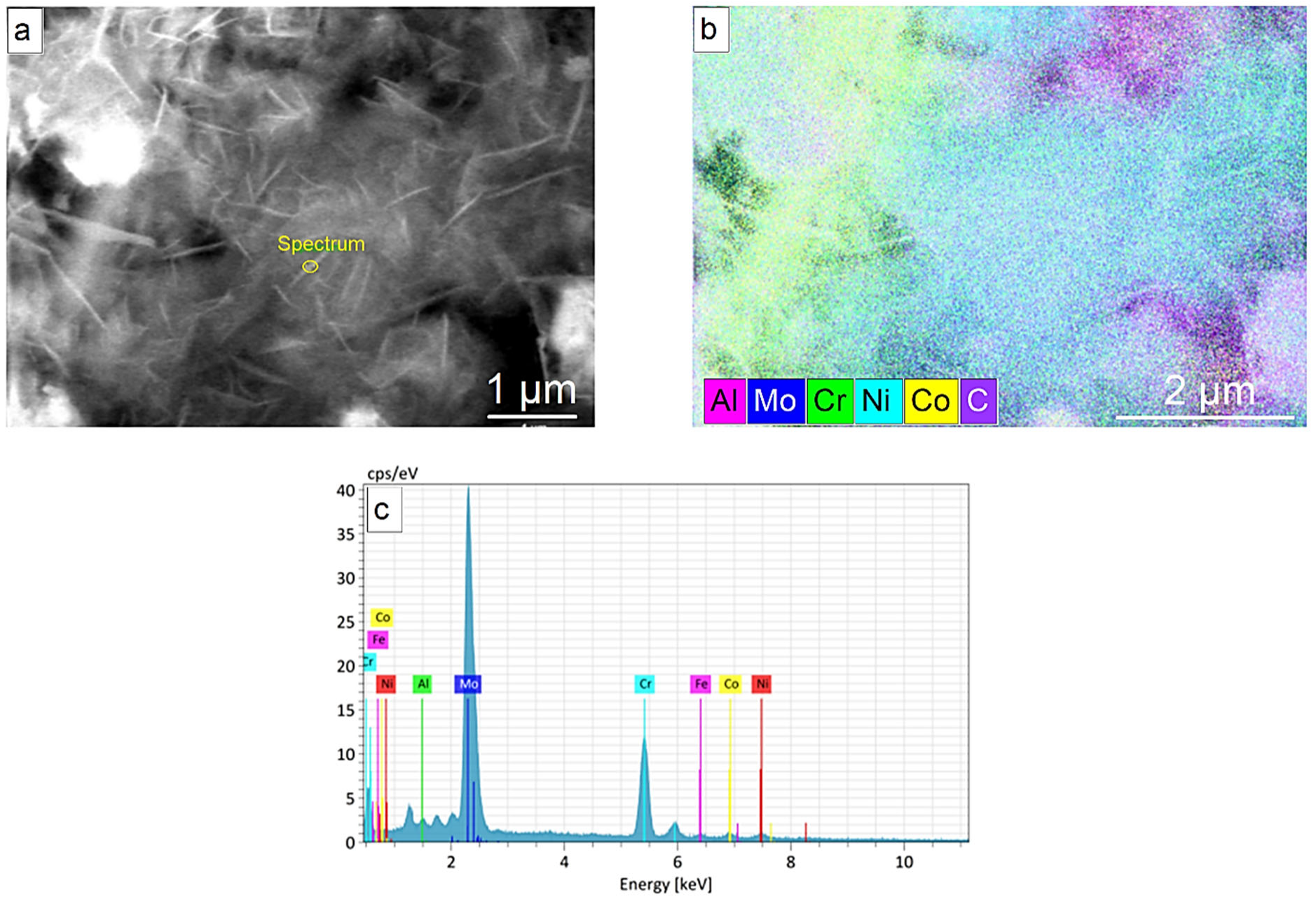
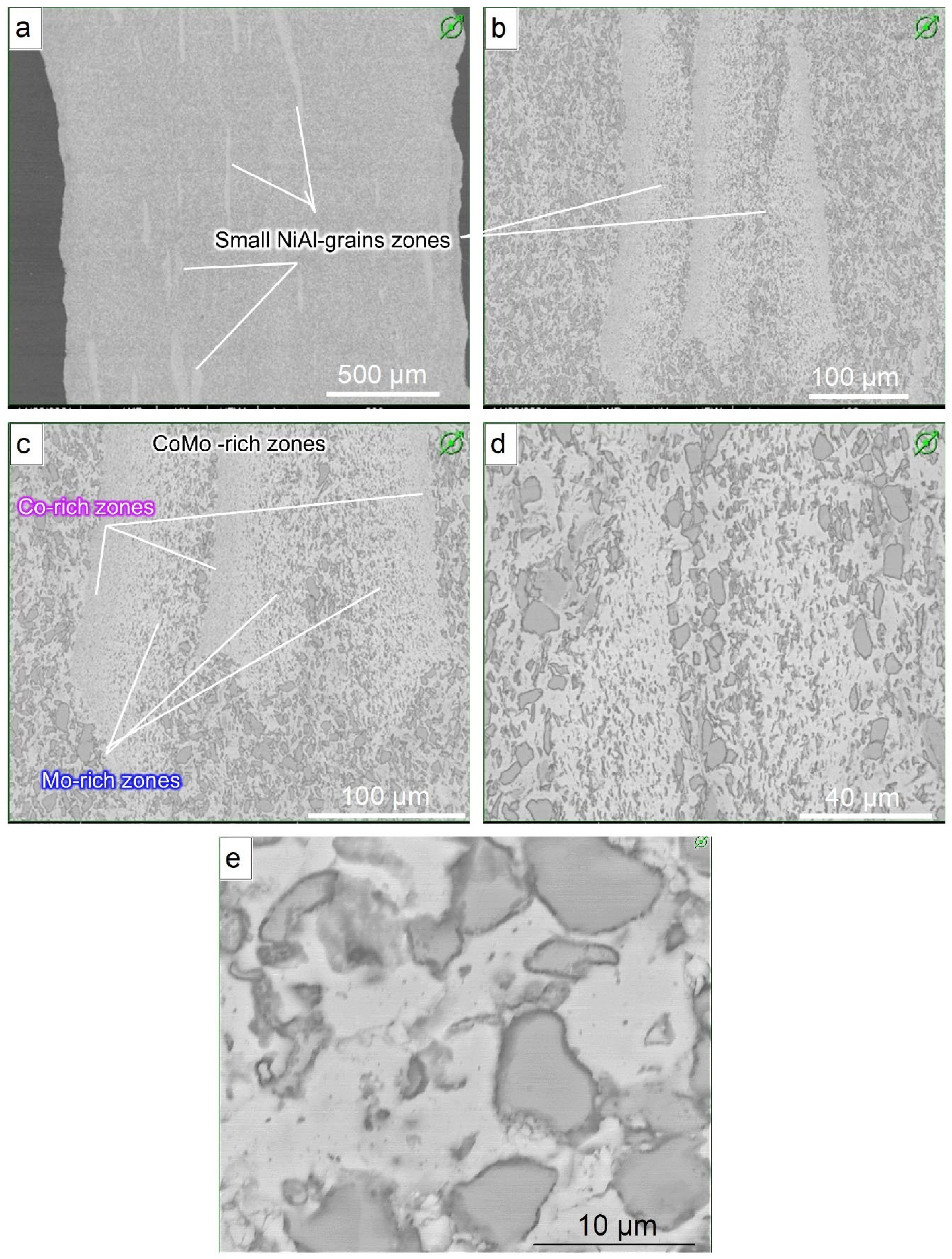
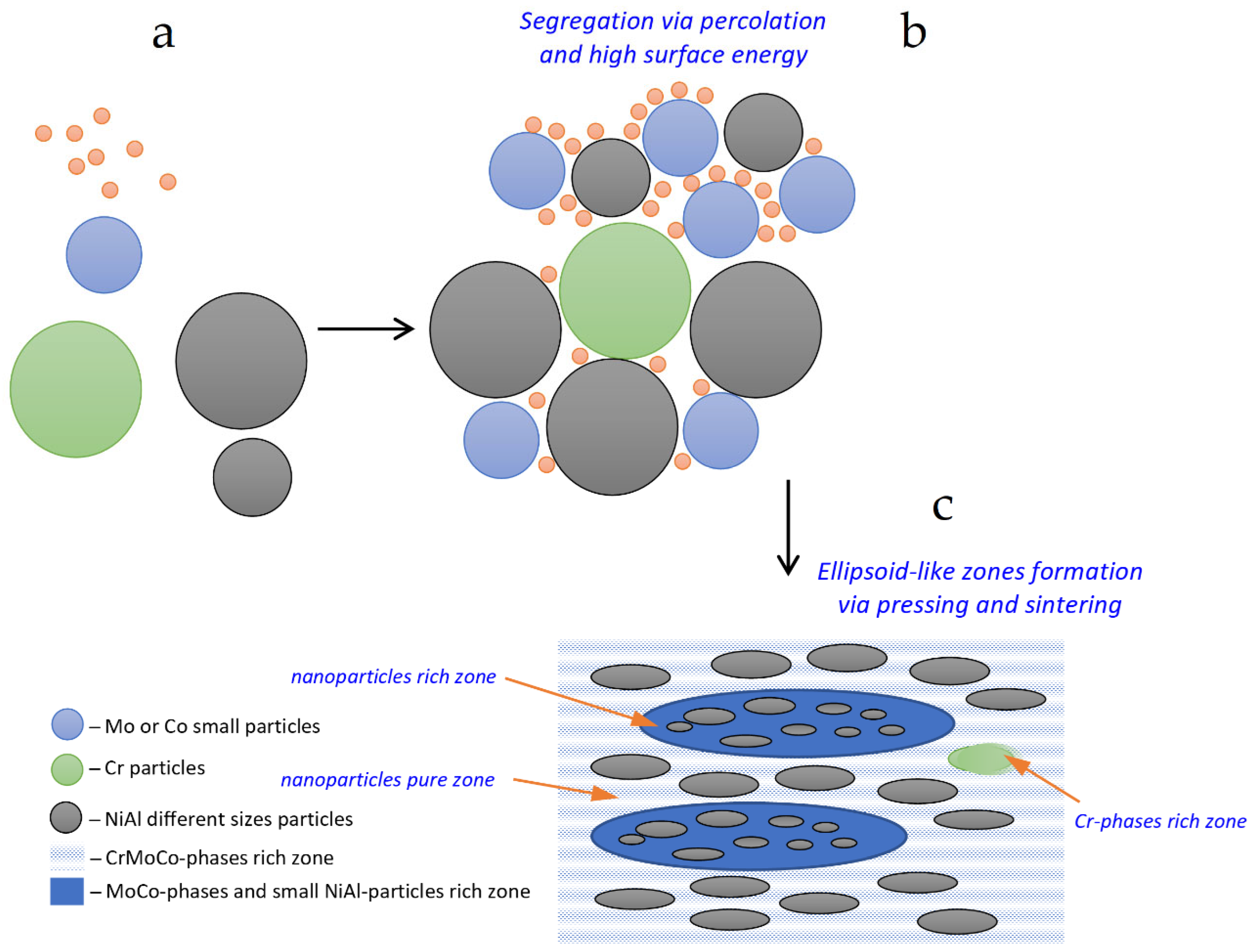
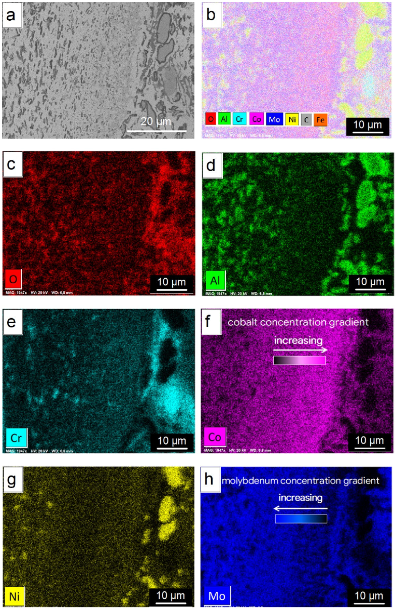
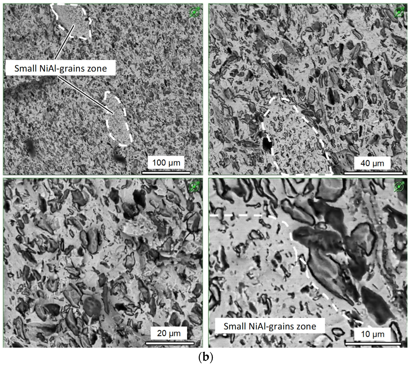
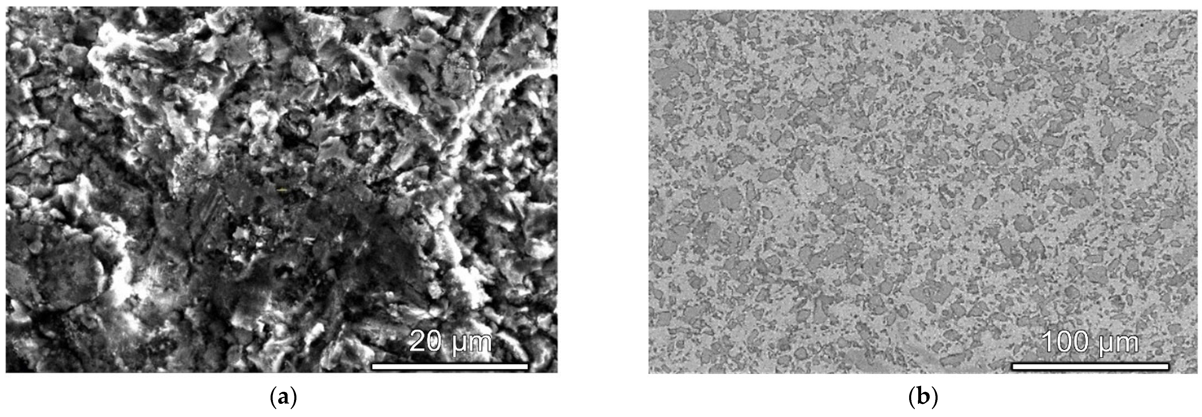
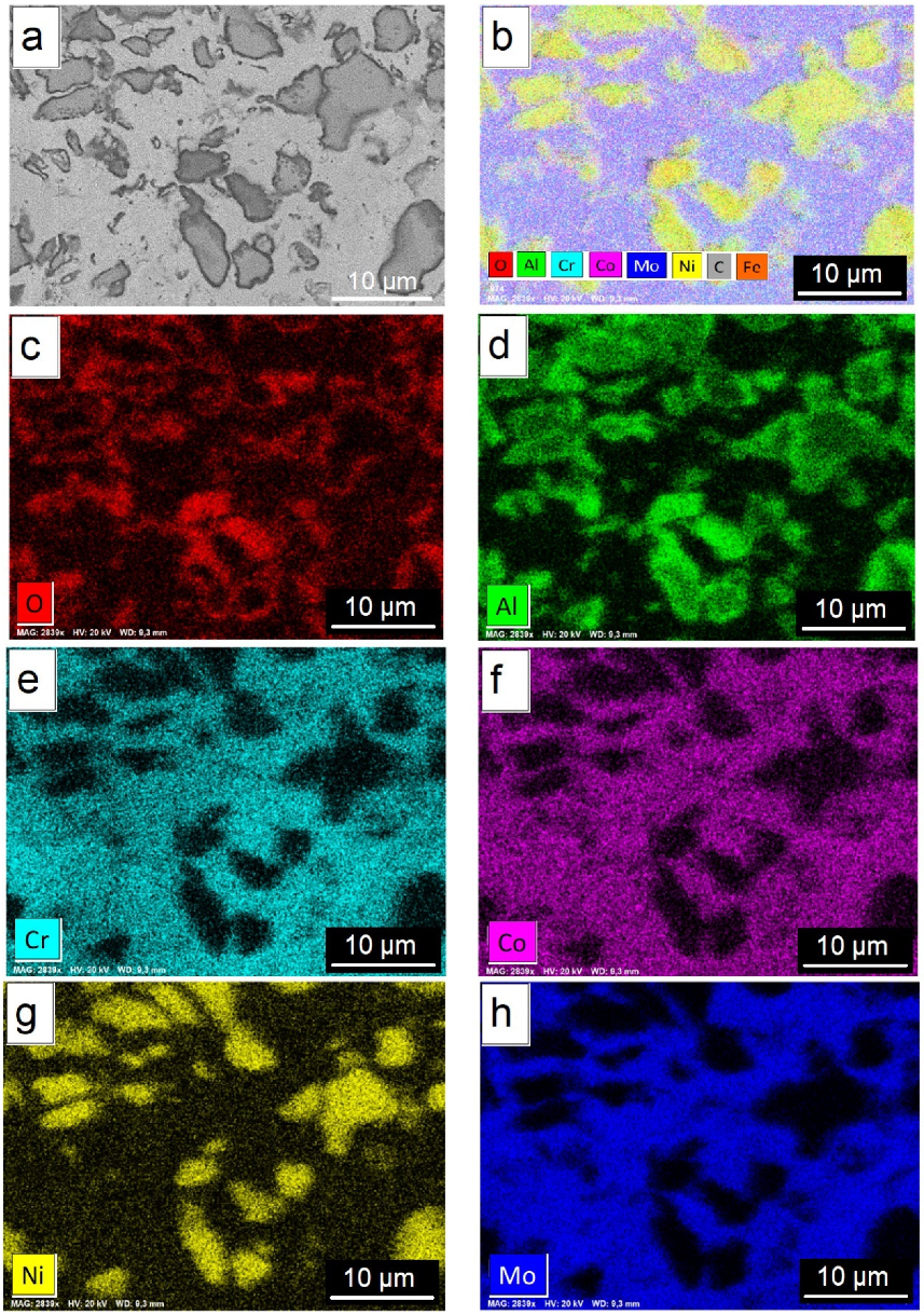
3.4. Microstructure and Composition

Figure 5 shows the microstructure of alloy without nanoparticle additions before and after polishing. It contained two types of areas: light gray areas and duck particles of irregular form and with size up to 10 μm.
X-ray microanalysis mapping (Figure 6) showed that light gray areas contained mainly Cr, Mo, Co and duck particles—mainly Ni and Al. It was also noticeable that aluminum and oxygen were distributed along the grain perimeter of the dark gray particles, which was associated with the presence of an oxide film. It could be assumed that the light gray areas corresponded to BCC solid solution or mixed FCC–BCC structure, where large particles of B2 intermetallic compound, based on the NiAl phase, were located.
In addition, there were differently oriented nanoscale flat particles located inside the “matrix”. The light gray phase (Figure 5) was a solid solution of Cr–Mo–Co system, as well as a lamellar σ phase, which could be seen at a greater magnification (Figure 7). The spectrum referred to the high content acicular phase area. There was a predominance of molybdenum and chromium in this area.
Figure 8 shows the microstructure of the alloy with 0.01% addition of zirconium oxide nanoparticles. According to the elements distribution map, elongated wedge-shaped regions were enriched, on the one hand, with cobalt, and, on the other hand, with molybdenum, and also contained other elements of the matrix interspersed with nickel–aluminum particles.
This segregation was due to the features of mixing powders of various fractions, especially in the presence of nanoparticles. If one of the components is very small and the other is relatively large, it has been suggested that small particles can cover the surface of large particles. In this way, segregation does not occur, and it is possible to obtain a mixture that is more homogeneous than a random mixture [96,97], as shown in Figure 9. In this case, we had homogeneous zones in the sample. On the other hand, surface-active nanosized particles could combine with matrix particles with a higher surface energy compared to other larger matrix particles. The adhesion force of nanosized particles was 16 orders of magnitude less than for particles with a diameter of 10 µm. However, the relative adhesion force, considering the volume, for nanoparticles was 13 orders of magnitude greater than for non-nanosized ones. Thus, due to the size effect, the relative adhesion force of nanoparticles was significant and determined by an additional excess of surface energy [98]. Therefore, there were areas with gradient-sized particles in the sample. It was shown in [99,100] that, for systems of aluminum alloys, hardening with insoluble nanoparticles leads to the formation of elongated ellipsoidal regions, due to the segregation of nanoparticles. This effect prevents the growth of matrix grains. In this work, a similar effect was found. Nanoparticle additives formed such segregations due to their high surface energy and tendency to stick together with small particles of the matrix components, namely nickel–aluminum, chromium, molybdenum and cobalt (Figure 10). The height of such “wedges” was from tens to several hundred micrometers, and the width was several tens of micrometers.
Figure 11 shows the microstructure and distribution of elements in the wedge-shaped region in a sample with addition of nanoparticles. The region was enriched in cobalt and molybdenum, which was possibly associated with finer powders of these elements used in the matrix powder compared to chromium, for example. Moreover, the “wedges” were unevenly enriched in cobalt and molybdenum. The inter-wedge region seemed to be limited by sides with a high content of cobalt and molybdenum. Then there was a “partition” of areas with a large amount of molybdenum, and in the middle, there was a gradient of NiAl with molybdenum and chromium. The presence of Ni and Al in the same areas as Mo and Co showed the possibility of an intense interaction of Ni with Co and Mo, including the formation of TCP phases, and strong connections of Al with Ni.
Figure 12 shows an area with an increased content of the Co–Mo phase. Oxidized areas with high chromium content were clearly visible. There was an obvious area that contained an increased content of cobalt, in which nickel and chromium were dissolved, and another area, which was adjacent to the first, containing phases of the Co–Mo system.
Thus, the structure of the NiAl–CrMoCo alloy obtained in this work was a matrix containing nanoscale lamellar phases crossing each other. An acicular phase corresponded to the enriched phase (Cr, Mo) of the σ type. According to elements distribution maps, such elements as Cr, Mo, Ni segregated more intensively than Co and Al. At the same time, it was possible to distinguish areas enriched in the phase (Cr,Mo) with the plates of the σ type phase (Cr,Mo) inside. They were all located in the matrix, most likely, with the FCC and BCC–B2 structure. Iron was present in the alloy in an impurity amount due to milling during mechanical alloying in steel jars with steel grinding balls.

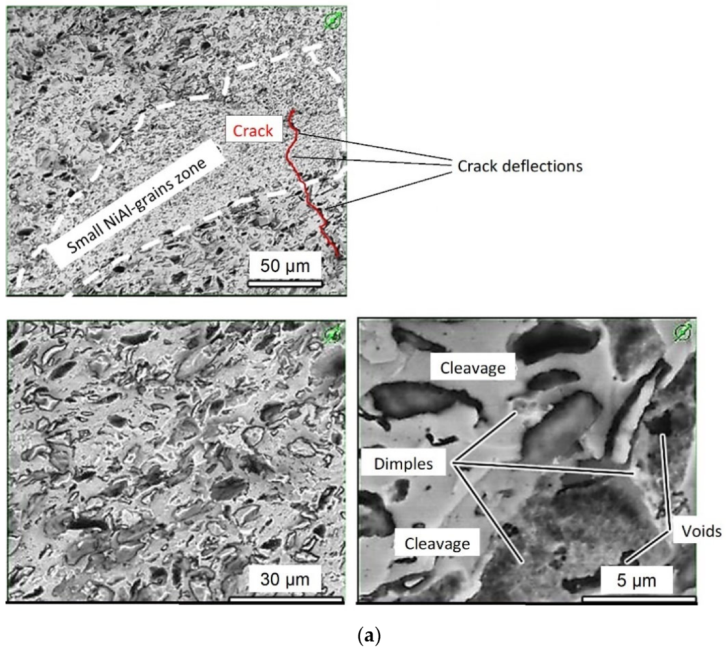
3.5. Fractographic Analysis

Bending strength studies were carried out using a three-point bending flexural test. Figure 13 shows the fracture structures of samples with nanoparticle additions. The destruction was predominantly brittle or ductile–brittle. Regions of a solid solution with a σ phase were visible, as well as regions of intermetallic grains, most likely the B2 BCC phase. In addition, a number of micrographs show areas with a fine-grained σ phase. Figure 13a shows how the crack was deflected and damped when passing through fine-grained and wedge-shaped regions. This effect increased the cracking resistance. The main difference in the fracture structure of the samples was that fine grain regions in a pure matrix were much rarer than in a sample modified with nanoparticles.
In Figure 13b, the areas of large pits are shown. Most likely they corresponded to NiAl phase grain before destruction. In the fracture, the cellular surface of the ‘CrMoCo’ phase was visible as was local ductile fracture initiated by the missing grain. The pores inside the large pits were probably where the NiAl grains presented.
The samples were characterized by brittle fractures, based on the areas of chips of the ‘CrMoCo’ phase. The material was destroyed mainly by a cleavage accompanied by microplastic deformation at the points of connection of the ‘CrMoCo’ phase with grains of the NiAl phase.

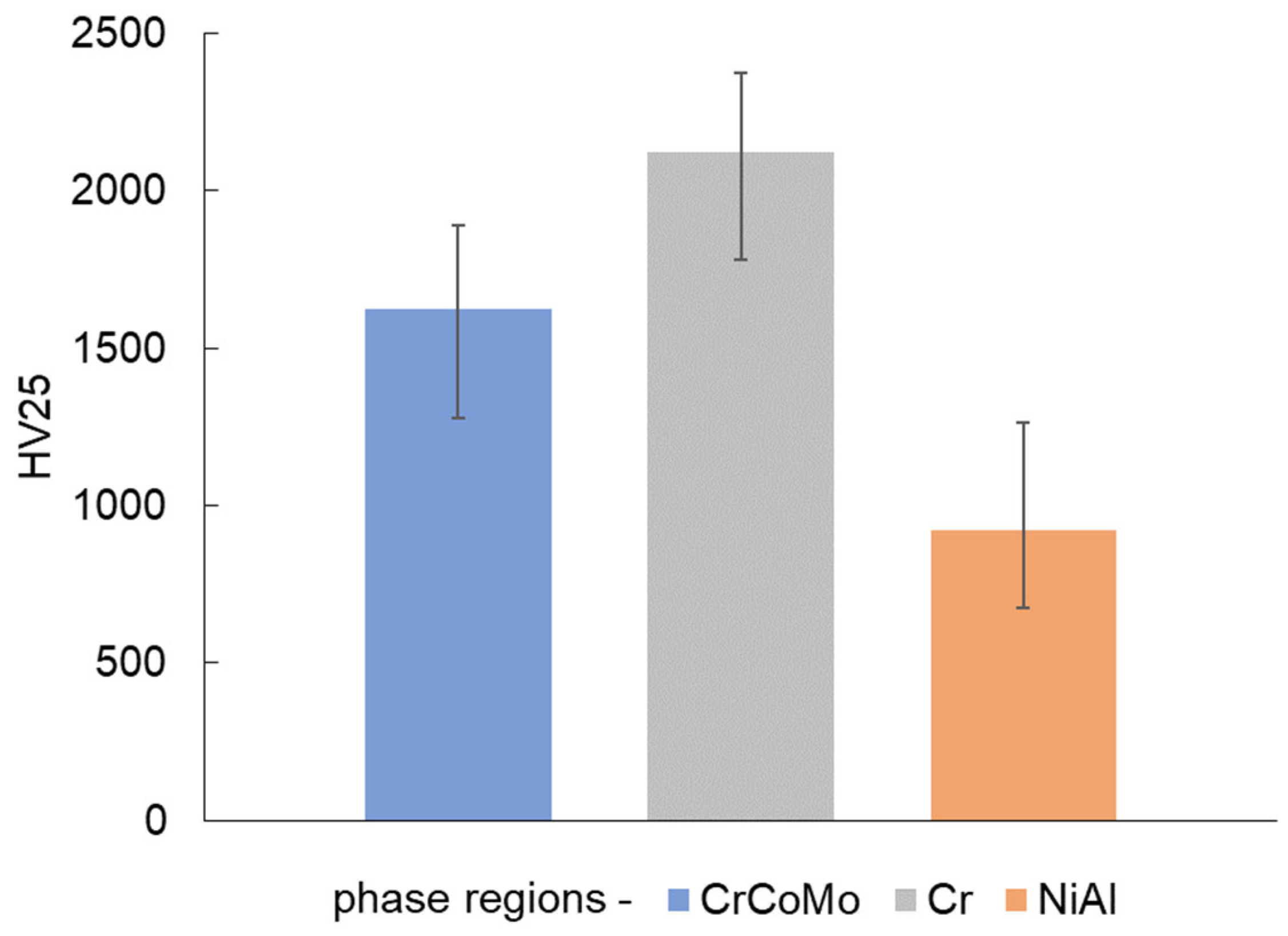
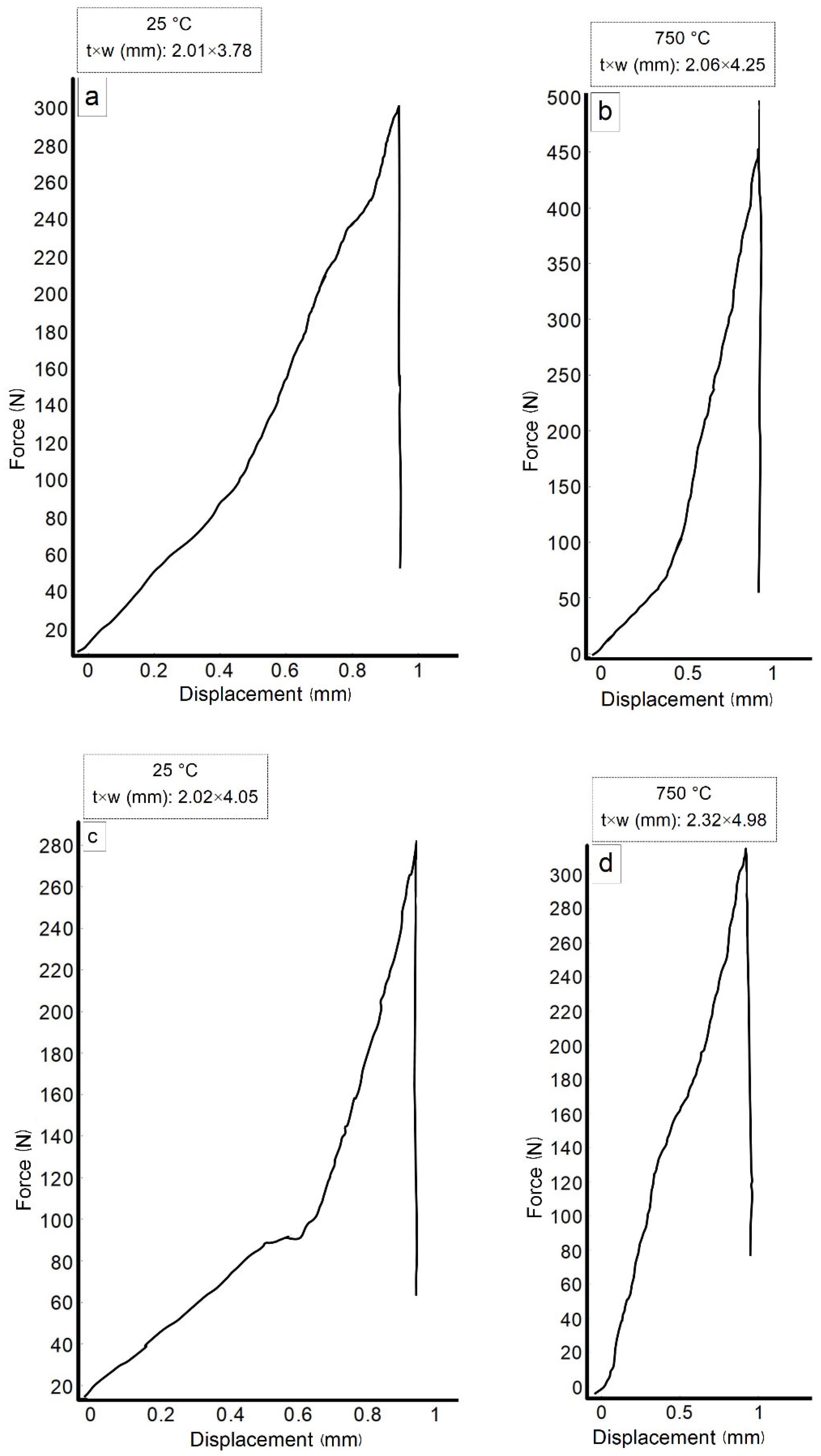
3.6. Mechanical Properties

Figure 14 shows the results of measuring the Vickers microhardness of various matrix material sample regions. The load was 25 g with an exposure of 20 s. The hardness of the matrix material phases regions enriched with chromium, NiAl and CrCoMo was measured. The region enriched with chromium had the highest hardness.
The results of measuring the bending strength of the alloy samples are shown in Figure 15 and Figure 16a. A sample with a crystalline matrix of NiAlCrMoCo with the addition of 0.01 wt. % nanoparticles of zirconium oxide had the highest strength of 611 MPa at room temperature and 604 MPa at 750 °C. The NiAlCrMoCo crystalline matrix sample had a strength of 504 and 474 MPa, at room temperature and 750 °C, respectively. Strength of single-crystal NiAl was about 305 MPa at room temperature and 429 MPa for heat-treated samples [1]. In [25] material NiAl-13at. % Cr-13at. % Mo-0.1 wt.% ZrO2 prepared in a similar way had the bending strength of 201 MPa at room temperature, and 473 MPa at 700 °C.
The change in the elastic modulus of samples without and with nanoparticles, depending on temperature, is shown in the Figure 16b. The modulus of the material without nanoparticles at room temperature was in the range of 283–289 GPa, and 251–255 GPa at 750 °C. Young’s modulus of the material modified by zirconium oxide nanoparticles were in the range of 290–295 GPa at room temperature and 257–260 GPa at 750 °C. For comparison, the Young’s modulus of NiAl were in the range of 180–218 GPa at 25 °C [101].
The reason for increasing the strength of reinforced with zirconium oxide nanoparticle alloy was better adhesion between particles, due to the high surface energy of nanoadditives, preventing the movement of dislocations by the Orowan mechanism, and the formation of a composite structure with elliptical zones “enriched” with nanoparticles.
The modulus of elasticity was slightly higher for the material modified with nanoparticles, due to the high modulus of zirconium oxide nanoparticles and, according to the Obraztsov–Lurie–Belov theory, the formation of gradient zones of change in its value from particle to matrix [102].

4. Conclusions

Thermodynamic modeling of the equilibrium phase composition of the NiAl–Cr,Mo,Co system in an equiatomic ratio with a small amount of C and O impurities vs. temperature was found using Terra® software. At sintering temperature, the main phases were NiAl, BCC–CoCr(ss) and FCC–NiCo(ss) solid solutions, as well as the close-packed TCP–CrMo phase. The amount of the Mo2C phase increased and the content of Cr23C6 decreased with temperature increasing. The presence of aluminum and chromium oxides was also found.
The microstructure of spark plasma method sintered samples consisted of a phase enriched with NiAl and CrMo. The material modified with a small amount of zirconium oxide nanoparticles had wedge-shaped elongated fine-grained regions, enriched in cobalt and molybdenum in the main matrix structure.
The highest strengths at the level of 611 MPa at room temperature and 604 MPa at 750 °C were from a sample with a crystalline matrix of NiAlCrMoCo with the addition of 0.01 nanoparticles of zirconium oxide. A sample of the NiAlCrMoCo system without nanoparticle additions had strengths of 504 and 474 MPa, respectively, at room temperature and 750 °C. The Young’s modulus of the material without nanoparticles at room temperature was 286 GPa, and 253 GPa at 750 °C, and for the material with zirconium oxide nanoparticles, 292.5 GPa at room temperature and 258.5 GPa at 750 °C.

Author Contributions

Conceptualization, L.A. and S.S.; methodology, S.S. and E.V.; software, L.A.; validation, S.S.; formal analysis, M.L.; investigation, L.A. and S.S.; resources, I.L.; data curation, I.L.; writing—original draft preparation, L.A.; writing—review and editing, S.S.; project administration, L.A. and M.L. All authors have read and agreed to the published version of the manuscript.

Funding

This research was funded by the Ministry of Science and Higher Education of the Russian Federation, grant number FSFF-2020–0014.

Informed Consent Statement

Not applicable.

Data Availability Statement

Not applicable.

Acknowledgments

The authors would like to acknowledge the support received by the employees of the Department of Nanotechnology of JSC “Keldysh Research Center” and for their assistance in the research and provision of valuable advice.

Conflicts of Interest

The authors declare no conflict of interest.

References

  1. Miracle, D.B. The physical and mechanical properties of NiAl. Acta Metall. 1993, 41, 649–684. [Google Scholar] [CrossRef]
  2. Noebe, R.D.; Bowman, R.R.; Nathal, M.V. Physical and mechanical properties of the B2 compound NiAl. Int. Mater. Rev. 1993, 38, 193–232. [Google Scholar] [CrossRef]
  3. George, E.P.; Liu, C.T. Brittle fracture and grain boundary chemistry of microalloyed NiAl. J. Mater. Res. 1990, 5, 754–762. [Google Scholar] [CrossRef]
  4. Barrett, C.A. Effect of 0.1 at.% Zirconium on the cyclic oxidation resistance of β-NiAl. Oxid. Met. 1988, 30, 361–390. [Google Scholar] [CrossRef]
  5. Ebrahimi, F.; Shrivastava, S. Brittle-to-ductile transition in NiAl single crystal. Acta Mater. 1998, 46, 1493–1502. [Google Scholar] [CrossRef]
  6. Walter, J.L.; Cline, H.E. The effect of solidification rate on structure and high-temperature strength of the eutectic NiAl-Cr. Metall. Mater. Trans. 1970, 1, 1221–1229. [Google Scholar] [CrossRef]
  7. Ferrandini, P.; Batista, W.W.; Caram, R. Influence of growth rate on the microstructure and mechanical behavior of a NiAl-Mo eutectic alloy. J. Alloys Compd. 2004, 381, 91–98. [Google Scholar] [CrossRef]
  8. Bei, H.; George, E.P. Microstructures and mechanical properties of a directionally solidified NiAl-Mo eutectic alloy. Acta Mater. 2005, 53, 69–77. [Google Scholar] [CrossRef]
  9. Zhang, J.F.; Shen, J.; Shang, Z.; Feng, Z.R.; Wang, L.S.; Fu, H.Z. Microstructure and room temperature fracture toughness of directionally solidified NiAl-Mo eutectic in situ composites. Intermetallics 2012, 21, 18–25. [Google Scholar] [CrossRef]
  10. Bogner, S.; Hu, L.; Hollad, S.; Hu, W.; Gottstein, G.; Bührig-Polaczek, A. Microstructure of a eutectic NiAl-Mo alloy directionally solidified using an industrial scale and a laboratory scale bridgman furnace. Int. J. Mater. Res. 2012, 103, 17–23. [Google Scholar] [CrossRef]
  11. Hu, L.; Hu, W.; Gottstein, G.; Bogner, S.; Hollad, S.; Bührig-Polaczek, A. Investigation into microstructure and mechanical properties of NiAl-Mo composites produced by directional solidification. Mater. Sci. Eng. A 2012, 539, 211–222. [Google Scholar] [CrossRef]
  12. Chen, X.F.; Johnson, D.R.; Noebe, R.D.; Oliver, B.F. Deformation and fracture of a directionally solidified NiAl-28Cr-6Mo eutectic alloy. J. Mater. Res. 1995, 10, 1159–1170. [Google Scholar] [CrossRef] [Green Version]
  13. Dudová, M.; Kuchařová, K.; Barták, T.; Bei, H.; George, E.P.; Somsen, C.; Dlouhý, A. Creep in directionally solidified NiAl-Mo eutectics. Scr. Mater. 2011, 65, 699–702. [Google Scholar] [CrossRef]
  14. Sanin, V.V.; Kaplansky, Y.Y.; Aheiev, M.I.; Levashov, E.A.; Petrzhik, M.I.; Bychkova, M.Y.; Samokhin, A.V.; Fadeev, A.A.; Sanin, V.N. Structure and Properties of Heat-Resistant Alloys NiAl–Cr–Co–X (X = La, Mo, Zr, Ta, Re) and Fabrication of Powders for Additive Manufacturing. Materials 2021, 14, 3144. [Google Scholar] [CrossRef] [PubMed]
  15. Dong, Z.; Sergeev, D.; Dodge, M.F.; Fanicchia, F.; Müller, M.; Paul, S.; Dong, H. Microstructure and Thermal Analysis of Metastable Intermetallic Phases in High-Entropy Alloy CoCrFeMo0.85Ni. Materials 2021, 14, 1073. [Google Scholar] [CrossRef] [PubMed]
  16. Shun, T.-T.; Chang, L.-Y.; Shiu, M.-H. Microstructure and mechanical properties of multiprincipal component CoCrFeNiMox alloys. Mater. Charact. 2012, 70, 63–67. [Google Scholar] [CrossRef]
  17. Mironov, V.V.; Agureev, L.E.; Eremeeva, Z.V.; Kostikov, V.I. Dependence of the strength properties of aluminum materials on the concentration of ZrO2 nanoparticles. Dokl. Phys. Chem. 2019, 485, 63–65. [Google Scholar] [CrossRef]
  18. Chuvil’deev, V.N.; Kopylov, V.I.; Zeiger, W. Non-equilibrium grain boundaries. Theory and its applications for describing nano- and microcrystalline materials processed by ECAP. Ann. Chim. Sci. Mater. 2002, 27, 55–64. [Google Scholar]
  19. Ohji, T.; Hirano, T.; Nakahira, A.; Niihara, K. Particle/Matrix interface and its role in creep inhibition in aluminasilicon carbide nanocomposites. J. Am. Ceram. Soc. 1996, 79, 33–45. [Google Scholar] [CrossRef]
  20. Grigorovich, V.K.; Sheftel, E.N. Dispersion Hardening of Refractory Metals; Nauka: Moscow, Russia, 1980. (In Russian) [Google Scholar]
  21. Gottstein, G. Physical Foundations of Materials Science; Springer: Berlin/Heidelberg, Germany, 2004; 502p. [Google Scholar]
  22. Thompson, A.W. Substructure strengthening mechanisms. Met. Trans. 1977, 8, 833–842. [Google Scholar] [CrossRef]
  23. Lugovskoi, Y.F. Effect of structure on the fatigue strength of dispersion-hardened condensated based on copper II. Analysis of the first coefficient of the Mott—Stroh relation. Powder Metall. Met. Ceram. 1998, 37, 432–437. [Google Scholar] [CrossRef]
  24. Taira, S.; Otani, R. Theory of High Temperature Strength of Materials; Metallurgiya: Moscow, Russia, 1986. (In Russian) [Google Scholar]
  25. Agureev, L.; Kostikov, V.; Savushkina, S.; Eremeeva, Z.; Lyakhovetsky, M. Preparation and Study of Composite Materials of the NiAl-Cr-Mo-Nanoparticles (ZrO2, MgAl2O4) System. Materials 2022, 15, 5822. [Google Scholar] [CrossRef]
  26. Rogal, Ł.; Szklarz, Z.; Bobrowski, P.; Kalita, D.; Garzeł, G.; Tarasek, A.; Szlezynger, M. Microstructure and Mechanical Properties of Al–Co–Cr–Fe–Ni Base High Entropy Alloys Obtained Using Powder Metallurgy. Met. Mater. Int. 2019, 25, 930–945. [Google Scholar] [CrossRef] [Green Version]
  27. Stryzhyboroda, O.; Witusiewicz, V.T.; Gein, S.; Röhrens, D.; Hecht, U. Phase Equilibria in the Al–Co–Cr–Fe–Ni High Entropy Alloy System: Thermodynamic Description and Experimental Study. Front. Mater. 2020, 7, 270. [Google Scholar] [CrossRef]
  28. Hecht, U.; Gein, S.; Stryzhyboroda, O.; Eshed, E.; Osovski, S. The BCC-FCC Phase Transformation Pathways and Crystal Orientation Relationships in Dual Phase Materials from Al-(Co)-Cr-Fe-Ni Alloys. Front. Mater. 2020, 7, 287. [Google Scholar] [CrossRef]
  29. Dong, Y.; Lu, Y.; Kong, J.; Zhang, J.; Li, T. Microstructure and mechanical properties of multi-component AlCrFeNiMox high-entropy alloys. J. Alloys Compd. 2013, 573, 96–101. [Google Scholar] [CrossRef]
  30. Mathiou, C.; Giorspyros, K.; Georgatis, E.; Poulia, A.; Karantzalis, A.E. NiAl-Cr-Mo Medium Entropy Alloys: Microstructural Verification, Solidification Considerations, and Sliding Wear Response. Materials 2020, 13, 3445. [Google Scholar] [CrossRef] [PubMed]
  31. Available online: http://www.diva-portal.org/smash/get/diva2:447253/FULLTEXT01.pdf (accessed on 28 October 2022).
  32. Shun, T.-T.; Du, Y.-C. Age hardening of the Al0.3CoCrFeNiC0.1 high entropy alloy. J. Alloys Compd. 2009, 478, 269–272. [Google Scholar] [CrossRef]
  33. Fang, S.; Chen, W.; Fu, Z. Microstructure and mechanical properties of twinned Al0.5CrFeNiCo0.3C0.2 high entropy alloy processed by mechanical alloying and spark plasma sintering. Mater. Des. 2014, 54, 973–979. [Google Scholar] [CrossRef]
  34. Chen, M.-R.; Lin, S.-J.; Yeh, J.-W.; Chen, S.-K.; Huang, Y.-S.; Tu, C.-P. Microstructure and Properties of Al0.5CoCrCuFeNiTix (x = 0-2.0) High-Entropy Alloys. Jpn. Inst. Met. 2006, 47, 1395–1401. [Google Scholar]
  35. Stepanov, N.; Yurchenko, N.Y.; Tikhonovsky, M.; Salishchev, G. Effect of carbon content and annealing on structure and hardness of the CoCrFeNiMn-based high entropy alloys. J. Alloys Compd. 2016, 687, 59–71. [Google Scholar] [CrossRef]
  36. Jiang, L.; Cao, Z.; Jie, J.; Zhang, J.; Lu, Y.; Wang, T.; Li, T. Effect of Mo and Ni elements on microstructure evolution and mechanical properties of the CoFeNixVMoy high entropy alloys. J. Alloys Compd. 2015, 649, 585–590. [Google Scholar] [CrossRef]
  37. Zaitsev, A.A. Structure and properties of NiAl-Cr(Co,Hf) alloys prepared by centrifugal SHS casting followed by vacuum induction remelting. Part 2–Evolution of the structure and mechanical behavior at high temperature. Mater. Sci. Eng. A 2017, 690, 473–481. [Google Scholar] [CrossRef]
  38. Cao, Y. First-principles study of NiAl alloyed with Co. Comput. Mater. Sci. 2016, 111, 34–40. [Google Scholar] [CrossRef]
  39. Li, H. Site preferences and effects of X (X = Mn, Fe, Co, Cu) on the properties of NiAl: A firstprinciples study. Mod. Phys. Lett. B. 2016, 30, 1650133–29. [Google Scholar] [CrossRef]
  40. Ponomareva, V.; Vekilova, Y.; Abrikosov, I. Effect of Re content on elastic properties of B2 NiAl from ab initio calculations. J. Alloys Compd. 2014, 586, 274–278. [Google Scholar] [CrossRef] [Green Version]
  41. Jha, S.C.; Ray, R. Carbide-dispersion-strengthened B2 NiAl. Mater. Sci. Eng. A 1989, 119, 103–111. [Google Scholar] [CrossRef]
  42. Logunov, A.V. Heat Resistant Nickel Alloys for Gas Turbine Blades and Discs; Mosuch: Moscow, Russia, 2018; 590p. (In Russian) [Google Scholar]
  43. Chen, L.; Han, Y. The microstructure and compressive properties in NiAl(Co) alloys by HPXD technique. Mater. Sci. Eng. A 2002, 329–331, 725–728. [Google Scholar] [CrossRef]
  44. Chung, D.H.; Liu, X.D.; Yang, Y. Fracture of sigma phase containing CoeCreNieMo medium entropy alloys. J. Alloys Comp. 2020, 846, 156–189. [Google Scholar] [CrossRef]
  45. Wang, W.; Wang, J.; Yi, H.; Qi, W.; Peng, Q. Effect of Molybdenum Additives on Corrosion Behavior of (CoCrFeNi)100−xMox High-Entropy Alloys. Entropy 2018, 20, 908. [Google Scholar] [CrossRef] [PubMed] [Green Version]
  46. Gasan, H.; Ozcan, A. New Eutectic High-Entropy Alloys Based on Co–Cr–Fe–Mo–Ni–Al: Design, Characterization and Mechanical Properties. Met. Mater. Int. 2020, 26, 1152–1167. [Google Scholar] [CrossRef]
  47. Liu, W.H.; Lu, Z.P.; He, J.Y.; Luan, J.H.; Wang, Z.J.; Liu, B.; Liu, Y.; Chen, M.W.; Liu, C.T. Ductile CoCrFeNiMox high entropy alloys strengthened by hard intermetallic phases. Acta Mater. 2016, 116, 332–342. [Google Scholar] [CrossRef]
  48. Shun, T.-T.; Chang, L.-Y.; Shiu, M.-H. Age-hardening of the CoCrFeNiMo0.85 high-entropy alloy. Mater. Charact. 2013, 81, 92–96. [Google Scholar] [CrossRef]
  49. Cai, B.; Liu, B.; Kabra, S.; Wang, Y.; Yan, K.; Lee, P.D.; Liu, Y. Deformation mechanisms of Mo alloyed FeCoCrNi high entropy alloy: In situ neutron diffraction. Acta Mater. 2017, 127, 2471–2480. [Google Scholar] [CrossRef] [Green Version]
  50. Hsu, C.Y.; Sheu, T.S.; Yeh, J.W.; Chen, S.K. Effect of iron content on wear behavior of AlCoCrFexMo0.5Ni high-entropy alloys. Wear 2010, 268, 653. [Google Scholar] [CrossRef]
  51. Hsu, C.Y.; Wang, W.R.; Tang, W.Y.; Chen, S.K.; Yeh, J.W. Microstructure and Mechanical Properties of New AlCoxCrFeMo0.5Ni High-Entropy Alloys. Adv. Eng. Mater. 2010, 12, 44–49. [Google Scholar] [CrossRef]
  52. Hsu, C.Y.; Juan, C.C.; Wang, W.R.; Sheu, T.S.; Yeh, J.W.; Chen, S.K. On the superior hot hardness and softening resistance of AlCoCrxFeMo0.5Ni high-entropy alloys. Mater. Sci. Eng. A 2011, 528, 3581–3588. [Google Scholar] [CrossRef]
  53. Juan, C.C.; Hsu, C.Y.; Tsai, C.W.; Wang, W.R.; Sheu, T.S.; Yeh, J.W.; Chen, S.K. On microstructure and mechanical performance of AlCoCrFeMo0.5Nix high-entropy alloys. Intermetallics 2013, 32, 401–407. [Google Scholar] [CrossRef]
  54. Wang, L.; Zhang, G.; Shen, J.; Zhang, Y.; Xu, H.; Ge, Y.; Fu, H. A true change of NiAl-Cr(Mo) eutectic lamellar structure during high temperature treatment. J. Alloys Compd. 2018, 732, 124–128. [Google Scholar] [CrossRef]
  55. Liu, Z.; Ning, H.; Lin, Z.; Wang, D. Influence of Spark Plasma Sintering Parameters on the Microstructure and Room-Temperature Mechanical Properties of NiAl-28Cr-5.5Mo-0.5Zr Alloy. Acta Metall. Sin. 2021, 57, 1579–1587. [Google Scholar]
  56. Röhrens, D.; Navaeilavasani, N.; Stryzhyboroda, O.; Swientek, F.; Pavlov, P.; Meister, D.; Genau, A.; Hecht, U. Microstructure and Mechanical Properties of BCC-FCC Eutectics in Ternary, Quaternary and Quinary Alloys from the Al-Co-Cr-Fe- Ni System. Front. Mater. 2020, 7, 324. [Google Scholar] [CrossRef]
  57. Wang, D.; Ning, H.; Wang, B.; Liu, W.; Yuan, S. Fabrication of a NiAl–Cr(Mo) eutectic alloy with network microstructure for high-temperature strengthening. Mater. Sci. Eng. A 2022, 835, 142628. [Google Scholar] [CrossRef]
  58. Demirtas, H.; Gungor, A. Effect of alloying elements on the microstructure and Mechanical properties of NiAl-Cr(Mo) eutectic alloy. International scientific journal "materials science. Non-Equilib. Phase Transform. 2015, 1, 25–29. [Google Scholar]
  59. Zhu, J.M.; Fu, H.M.; Zhang, H.F.; Wang, A.M.; Li, H.; Hu, Z.Q. Microstructures and compressive properties of multicomponent AlCoCrFeNiMox alloys. Mater. Sci. Eng. A 2010, 527, 6975–6979. [Google Scholar] [CrossRef]
  60. Kimura, Y.; Miura, S.; Suzuki, T.; Mishima, Y. Microstructure and mechanical properties of two-phase alloys based on the B2-type intermetallic compound CoAl in the Co-Al-Ni Ternary system. Mat. Trans. 1972, 35, 800–807. [Google Scholar] [CrossRef] [Green Version]
  61. Begunov, A.I.; Kuzmin, M.P. Thermodynamic Stability of Intermetallic Compounds in Technical Aluminum. J. Sib. Fed. Univ. Eng. Technol. 2014, 2, 132–137. [Google Scholar]
  62. Onderka, B.; Sypień, A.; Wierzbicka-Miernik, A.; Czeppe, T.; Zabdyr, L.A. Heat capacities of some binary intermetallic compounds in Al-Fe-Ni-Ti system. Arch. Metall. Mater. 2010, 55, 435–439. [Google Scholar]
  63. Yao, Z.-H.; Ruan, Y.-T.; Dong, J.-X.; Yu, Q.-Y.; Zhang, S.-Q.; Chen, X. Study on Gamma Prime and Carbides of Alloy A286 by Traditional Thermodynamic Calculation. High Temp. Mater. Proc. 2018, 37, 495–507. [Google Scholar] [CrossRef]
  64. Geramifard, G. Thermodynamic Investigation of Oxidation of Nial-(Cr, Mo) Alloys Used for Manufacturing Metal Matrix Composites by Directional Solidification; Karlsruher Institut für Technologie: Karlsruhe, Germany, 2021. [Google Scholar]
  65. Zhang, Z.; Li, M.; Flores, K.; Mishra, R. Machine learning formation enthalpies of intermetallics. J. Appl. Phys. 2020, 128, 105103. [Google Scholar] [CrossRef]
  66. Akande, T.; Matthew-Ojelabi, F.; Agunbiade, G.; Faweya, E. Thermodynamic properties of V, Cr, Mo, and Fe metals and their binary alloys. Turk. J. Phys. 2019, 43, 606–617. [Google Scholar] [CrossRef]
  67. Turchi, P.E.A.; Kaufman, L.; Liu, Z.-K. Modeling of Ni–Cr–Mo based alloys: Part I—Phase stability. Calphad 2006, 30, 70–87. [Google Scholar] [CrossRef]
  68. Cutler, R.W. The 1200 °C Isothermal Sections of the Ni-Al-Cr and the Ni-Al-Mo Ternary Phase. Master’s Thesis, The Ohio State University, Columbus, OH, USA, 2011. [Google Scholar]
  69. Peng, J. Experimental Investigation and Thermodynamic Modeling of the Al-Cr-Mo-Ni System and Its Subsystems. Ph.D. Thesis, Karlsruher Institut für Technologie, Karlsruhe, Germany, 2016. [Google Scholar]
  70. Sigli, C.; Kosugi, M.; Sanchez, J.M. Calculation of Thermodynamic Properties and Phase Diagrams of Binary Transition-Metal Alloys. Phys. Rev. Lett. 1986, 57, 253–256. [Google Scholar] [CrossRef] [PubMed]
  71. Chen, Q.; Huang, Z.; Zhao, Z.; Hu, C. First-principles study on the structural, elastic, and thermodynamics properties of Ni3X (X: Al, Mo, Ti, Pt, Si, Nb, V, and Zr) intermetallic compounds. Appl. Phys. A 2014, 116, 1161–1172. [Google Scholar] [CrossRef]
  72. Lide, D.R.; Kehiaian, H.V. CRC Handbook of Thermophysical and Thermochemical Data; Standard Reference Data National Institute of Standards and Technology; CRC Press: Boca Raton, FL, USA; New York, NY, USA, 1994. [Google Scholar]
  73. Oikawa, K.; Kattner, U.R.; Sato, J.; Omori, T.; Jiang, M.; Anzai, K.; Ishida, K. Experimental Determination and Thermodynamic Assessment of Phase Equilibria in the CoMo System. Mater. Trans. 2012, 11, M2012149. [Google Scholar]
  74. Rajan, K. Thermodynamic assessment of heat treatments for a Co-Cr-Mo alloy. J. Mater. Sci. 1983, 18, 257–264. [Google Scholar] [CrossRef]
  75. Jindal, V. A thermodynamic assessment of the Cr–Mo system using CE-CVM. Calphad 2013, 43, 80–85. [Google Scholar] [CrossRef]
  76. Colinet, C.; Tedenac, J.-C. Enthalpies of formation of TM–X compounds(X-Al, Ga,Si,Ge,Sn). Comparison of ab-initio values and experimental data. Calphad Comput. Coupling Phase Diagr. Thermochem. 2016, 54, 16–34. [Google Scholar] [CrossRef]
  77. Rank, M.; Gotcu, P.; Franke, P.; Seifert, H.J. Thermodynamic investigations in the Al-Fe system: Heat capacity measurements of three intermetallic phases. Intermetallics 2018, 94, 73–82. [Google Scholar] [CrossRef]
  78. Yao, Q.; Shang, S.-L.; Wang, K.; Liu, F.; Wang, Y.; Wang, Q.; Lu, T.; Liu, Z.K. Phase stability, elastic, and thermodynamic properties of the L12 (Co,Ni)3(Al,Mo,Nb) phase from first-principles calculations. J. Mater. Res. 2017, 32, 2100–2108. [Google Scholar] [CrossRef]
  79. Wang, Y.; Liu, Z.-K.; Chen, L.-Q. Thermodynamic properties of Al, Ni, NiAl, and Ni3Al from first-principles calculations. Acta Mater. 2004, 52, 2665–2671. [Google Scholar] [CrossRef]
  80. Asadikiya, M.; Drozd, V.; Yang, S.; Zhong, Y. Enthalpies and Elastic Properties of Ni-Co Binary System by ab initio Calculations and an Energy Comparison with the CALPHAD Approach. Mater. Today Commun. 2020, 23, 100905. [Google Scholar] [CrossRef]
  81. Liu, X.L.; Gheno, T.; Lindahl, B.B.; Lindwall, G.; Gleeson, B.; Liu, Z.-K. First-Principles Calculations, Experimental Study, and Thermodynamic Modeling of the Al-Co-Cr System. PLoS ONE 2015, 10, e0121386. [Google Scholar] [CrossRef] [PubMed] [Green Version]
  82. Kuzmin, M.P.; Begunov, A.I. Priblizhonnyye raschoty termodinamicheskikh kharakteristik intermetallicheskih soedinenij na osnove alyuminiya. Vestn. IrGTU 2013, 72, 98–101. (In Russian) [Google Scholar]
  83. Moiseyev, G.K.; Vatolin, N.A.; Marshuk, L.A.; Il’inykh, N.I. Temperaturnyye Zavisimosti Privedennoy Energii Gibbsa Nekotorykh Neorganicheskikh Veshchestv (Al’ternativnyy Bank Dannykh ACTPA.OWN); UrO RAN: Yekaterinburg, Russia, 1997; 231p. (In Russian) [Google Scholar]
  84. Khina, B.B. Thermodynamic Models of Condensed Phases and Their Application in Materials Science. Adv. Mater. Technol. 2018, 1, 41–47. [Google Scholar] [CrossRef]
  85. Kubashevskij, O.; Olkokk, S.B. Metallurgicheskaja Termohimija [Metallurgical Thermochemistry]; Metallurgija: Moscow, Russia, 1982; 392p. (In Russian) [Google Scholar]
  86. Moiseyev, G.K. Otsenka termokhimicheskikh svoystv i termodinamicheskikh funktsiy nekotorykh letuchikh i kondensirovannykh klasterov shchelochnykh metallov (SHCHM). RASPL 2003, 4, 59–84. (In Russian) [Google Scholar]
  87. Gurvich, L.V.; Bergman, G.A.; Veitz, I.V.; Medvedev, V.A.; Khachkuruzov, G.A.; Yungman, V.S. Thermodynamic Properties of Individual Substances; Glushko, V.P., Ed.; High Temperature Institute: Moscow, Russia, 1982; Volume 1–4. [Google Scholar]
  88. Berdnikov, V.I.; Gudim, Y.A. Termodinamicheskiye svoystva binarnykh metallichskikh sistem, soderzhashchikh intermetallidnyye soyedineniya. Izv. Vyssh. Uch. Zaved. Chern. Met. 2013, 5, 37–41. (In Russian) [Google Scholar]
  89. Maier, C.G.; Kelly, K.K. An equation for the representation of high temperature heat content data. J. Am. Chem. Soc. 1932, 54, 3243–3246. [Google Scholar] [CrossRef]
  90. Morachevskiy, A.G.; Sladkov, I.B. Termodinamicheskie Raschety v Metallurgii: Spravochnik (Thermodynamic Calculations in Metallurgy: Reference Book); Metallurgia: Moscow, Russia, 1993; 304p. [Google Scholar]
  91. Perry, R.H.; Green, D.W. (Eds.) Perry’s Chemical Engineer’s Handbook, 7th ed.; McGraw-Hill: New York, NY, USA, 1997. [Google Scholar]
  92. Ilinykh, N.I.; Krivorogova, A.S.; Gelchinsky, B.R.; Ilinykh, S.A.; Leontiev, L.I. Thermodynamic modeling of Ni-Cr-B-C-Si system in "air+propane" atmosphere. J. Phys. Conf. Ser. 2021, 1954, 012012. [Google Scholar] [CrossRef]
  93. Gelchinski, B.R.; Balyakin, I.A.; Ilinykh, N.I.; Rempel, A.A. Analysis of the Probability of Synthesizing High-Entropy Alloys in the Systems Ti-Zr-Hf-V-Nb, Gd-Ti-Zr-Nb-Al, and Zr-Hf-V-Nb-Ni. Phys. Mesomech. 2021, 24, 701–706. [Google Scholar] [CrossRef]
  94. Khil’ko, A.A.; Simonyan, L.M.; Glinskaya, I.V. Determining the composition of electrosmelting dust. Steel Transl. 2014, 44, 1–5. [Google Scholar] [CrossRef]
  95. Vatolin, N.L.; Moiseev, G.K.; Trusov, B.G. Thermodynamic Simulation in High-Temperature Inorganic Systems; Metallurgia: Moscow, Russia, 1994; 352p. [Google Scholar]
  96. Williams, J.C. Mixing and segregation in powders. In Principles of Powder Technology; Martin, R., Ed.; John Wiley and Sons: Hoboken, NJ, USA, 1992; pp. 71–90. [Google Scholar]
  97. Hersey, J.A.; Thiel, W.J.; Yeung, C.C. Partially ordered randomized powder mixtures. Powder Technol. 1979, 24, 251–256. [Google Scholar] [CrossRef]
  98. Zimon, A.D.; Pavlov, A.N. Colloidal Chemistry of Nanoparticles; Scientific World: Singapore, 2012; 224p. (In Russian) [Google Scholar]
  99. Kostikov, V.I.; Agureev, L.E.; Eremeeva, Z.V. Development of nanoparticle-hardened aluminum composites for rocket and space technology. Russ. J. Non-Ferr. Met. 2015, 56, 325–328. [Google Scholar] [CrossRef]
  100. Jiang, L.; Yang, H.; Yee, J.K.; Mo, X.; Topping, T.; Lavernia, E.J.; Schoenung, J.M. Toughening of aluminum matrix nanocomposites via spatial arrays of boron carbide spherical nanoparticles. Acta Mater. 2016, 103, 128–140. [Google Scholar] [CrossRef] [Green Version]
  101. Ponomareva, A.V.; Isaev, E.; Vekilov, Y.K.; Abrikosov, I. Site preference and effect of alloying on elastic properties of ternary B2 NiAl-based alloys. Phys. Rev. B. Condens. Matter Mater. Phys. 2012, 85, 144117. [Google Scholar] [CrossRef] [Green Version]
  102. Lurie, S.; Volkov-Bogorodskiy, D.; Solyaev, Y.; Rizahanov, R.; Agureev, L. Multiscale modelling of aluminium-based metal-matrix composites with oxide nanoinclusions. Comput. Mater. Sci. 2016, 116, 62–73. [Google Scholar] [CrossRef]
Figure 1. The microstructure of powder mixture.
Metals 12 02014 g001
Figure 2. Curves of TGA (solid blue line), DTG (dashed blue line) and DSC (red line) of the NiAl–Cr–Mo–Co sample.
Metals 12 02014 g002
Figure 3. XRD pattern of sintered NiAl–CrMoCo matrix.
Metals 12 02014 g003
Figure 4. Thermodynamic modeling of the system equilibrium composition (a) and temperature dependences of the total enthalpy (b) and entropy (c) of the system.
Metals 12 02014 g004aMetals 12 02014 g004b
Figure 5. Microstructure of an unpolished surface (a) and a polished sample (b,c) of an alloy without nanoparticles.
Metals 12 02014 g005aMetals 12 02014 g005b
Figure 6. Elements distribution map in an alloy without nanoparticles: (a) microstructure, (b) all elements distribution, (c) O, (d) Al, (e) Cr, (f) Co, (g) Ni, (h) Mo.
Metals 12 02014 g006
Figure 7. SEM image (a), elements distribution map (b) and x-ray microanalysis spectrum (c) in the area with predominance of lamellar phase.
Metals 12 02014 g007
Figure 8. Microstructure of an alloy sample with a small addition of zirconium oxide nanoparticles: (a) general view, (bd) emphasis on fine grained zones with segregation of alloying components, (e) general view at higher magnification.
Metals 12 02014 g008
Figure 9. Illustration of the Segregation mechanisms of particles with different diameters during mixing: (a) adhesion of smaller particles to “medium” particles, (b) segregation of “coated” particles and larger particles, (c) formation of elliptical zones with fine grains enriched in cobalt and molybdenum.
Metals 12 02014 g009
Figure 10. Wedge-shaped regions enriched with various alloy components scheme.
Metals 12 02014 g010
Figure 11. Microstructure and elements’ distribution maps in the wedge-shaped region: (a) microstructure, (b) all elements, (c) O, (d) Al, (e) Cr, (f) Co, (g) Ni, (h) Mo.
Metals 12 02014 g011
Figure 12. Microstructure image and elements’ distribution maps in the gradient area: (a) microstructure, (b) all elements, (c) O, (d) Al, (e) Cr, (f) Co, (g) Ni, (h) Mo.
Metals 12 02014 g012
Figure 13. Fracture of alloy with zirconium oxide nanoparticles: (a) crack deflection and local ductile fracture, (b) small-grains zone.
Metals 12 02014 g013aMetals 12 02014 g013b
Figure 14. The results of the microhardness measuring of the phase regions of the matrix sample.
Metals 12 02014 g014
Figure 15. Force–displacement curves of pure matrix at 25 °C (a) and 750 °C (b) and matrix with 0.01 wt. % of ZrO2 nanoparticles at 25 °C (c) and 750 °C (d); t—thickness, w—width, length in all cases 18 mm.
Metals 12 02014 g015
Figure 16. Bending strength (a) and Young’s modulus (b) of composites at test temperatures of 25 °C and 750 °C.
Metals 12 02014 g016
Table 1. Alloys based on transition metals, composition and properties.
Alloys Composition
(HT—Heat Treated)
Material TypePhase StructurePreparation MethodMechanical Properties at 25 °CReferences
AlCrFe(0.6;1)CoNiMo0.5HEABCC + σarc smelting750 HV (Fe 0.6)
725 HV(Fe 1)
[50]
AlCrFeCo(1;1.5)NiMo0.5HEA780 HV(Co1)
730 HV(Co1.5)
[51]
AlCrFeCo2NiMo0.5HEAFCC + BCC + σ600 HV[51]
AlCr(1;1.5;2)FeCoNiMo0.5HEABCC + σ725 HV(Cr1)
810 HV(Cr1)
860 HV(Cr2)
[52,53]
AlCrCoFeMo0.5Ni(1.5;2)HEAFCC + BCC + σ-[53]
NiAl-28Cr-5.5Mo-0.5Hf at.%eutectic alloyCr(Mo)—plates, NiAl, Ni2AlHf (Heusler)induction melting-[54]
NiAl-20Cr-20Mo at.%eutectic alloyBCC-B2 NiAl, BCC-Cr, AlMo3, NiMo orth., oxidearc melting680 HV[30]
NiAl-15Cr-25Mo at.%eutectic alloyBCC-B2 NiAl, BCC-Cr, NiMo orth.650 HV
NiAl-28Cr-5.5Mo-0.5Zr at.%eutectic alloyNiAl, Cr(Mo)SPSYS 1321 MPa
UCS 2360 MPa
plasticity strain 0.313
[55]
NiAl-13Cr-13Mo, at.%
(modified with 0.01 wt.% ZrO2)
eutectic alloyNiAl, (CrMo), Al5MoMA + SPSbending strength
210 MPa (at 20 °C)
475 MPa (at 700 °C).
[25]
Ni34.4Fe16.4Co16.4Cr16.4Al16.4
HT 750 °C (at.%)
HEAcellular/“dendritic” eutectic,
BCC-B2,
FCC-A1
arc meltingflexural yield strength reached 1291 MPa;
ultimate flexure strength 1968 MPa
[56]
NiAl–28Cr-5.5Mo-0.5Zr (at.%)eutectic alloyNiAl, Cr(Mo), Heuslermetallic powders were obtained by atomization technique, then hot pressingUTS 405 MPa (at 1000 °C)
1300 MPa (25 °C)
[57]
Ni-29Al-28Cr-6Mo-4Ti
HT at 1300 °C
eutectic alloyNiAl, Cr(Mo), Ni2AlTivacuum arc
melting
UCS
3430 MPa;
YS 1549 MPa
340 MPa (at 1000 °C)
YS 293 MPa
401HB
εy 3.6%
εu 27.71%
[58]
NiAl-5.5Co-11Cr-8 Mo at.%eutectic alloyNiAl, (Ni,Cr,Co)3Mo3C, Ni3Al, Cr(Mo)centrifugal SHS castingUCS 1728 MPa
YS 1566 MPa
degree of plastic deformation εpd
0.95%
[21]
CoCrFeNiMo0.3
HT 1173K, 5 h or 2 days
HEAFCC + σ (5 h)
FCC + σ+μ (2 days)
arc meltingUTS/YS/El%
709/305 MPa/49.3 (as cast)
1186/815 MPa/18.9 (1123 K, 1 h),
1042/646 MPa/32.5 (1173 K, 5 h)
[47]
CoCrFeMo0.85NiHEA powder alloyFCC, μ, σgas atomization-[22]
CoCrFeNiMo0.85HEAFCC-A1, σ, μ-D85 (same as Co7Mo6)arc meltingas the Mo content increases from 0 to 0.85, the yield stress and compressive strength rise from 136 MPa and 871 MPa to 929 MPa and 1441 MPa.
fracture strain of 21 %,
[23]
AlCoCrFeNiMo0.5HEAOnly simple BCC solid solution structure and α phase are identified.arc meltingyield strength reached 2757 MPa when Mo content was 0.5;
Compressive strength max (MPa) 3036,
plastic strain 2.5%
[59]
Table 2. Thermodynamic properties of some substances used in the calculation.
CompoundCp (T)T, K C p , 298 0 ,
J/(kg·K)
H f ,   298 0 , J/mol S 298 0 , J/(mol·K) H 298 0 H 0 0 ,
J/mol
G 298 * , J/(mol·K)
abc
TCP-Co2Mo3114.2650.051−6.3141273–1893113.94−7000146.215,586.5325.078
TCP-Co7Mo6292.7960.145−12.627673–1783290.106−7000382.541,135.9385.316
Co9Mo2240.410.141−4.2091285–1473240.336−3000327.836,509.6701.215
Co3Mo13.332.4−0.3673–149888.7−5000118.813,220.5-
Table 3. Coefficients of the polynomial of the reduced Gibbs energy (J/(mol K)).
CompoundRange of T, KΦ = φ1 + φ2lnx + φ3x−2 + φ4x−1 + φ5x + φ6x2 + φ7x3, (x = T × 10−4, K)
φ1φ2φ3φ4φ5φ6φ7
TCP-Co2Mo31273–1893267.199114.2652−0.0031613.04110.257--
TCP-Co7Mo6673–1783878.350292.7961−0.00631515.78260.727--
Co9Mo21285–1473580.361240.41021−0.0021127.28620.708--
Co3Mo673–1498112.0513.3181−0.0309021.26433162.0035.02666.8
Publisher’s Note: MDPI stays neutral with regard to jurisdictional claims in published maps and institutional affiliations.

