
Leaching of Gold and Copper from Printed Circuit Boards under the Alternating Current Action in Hydrochloric Acid Electrolytes

 ,
,  ,
,  , , and
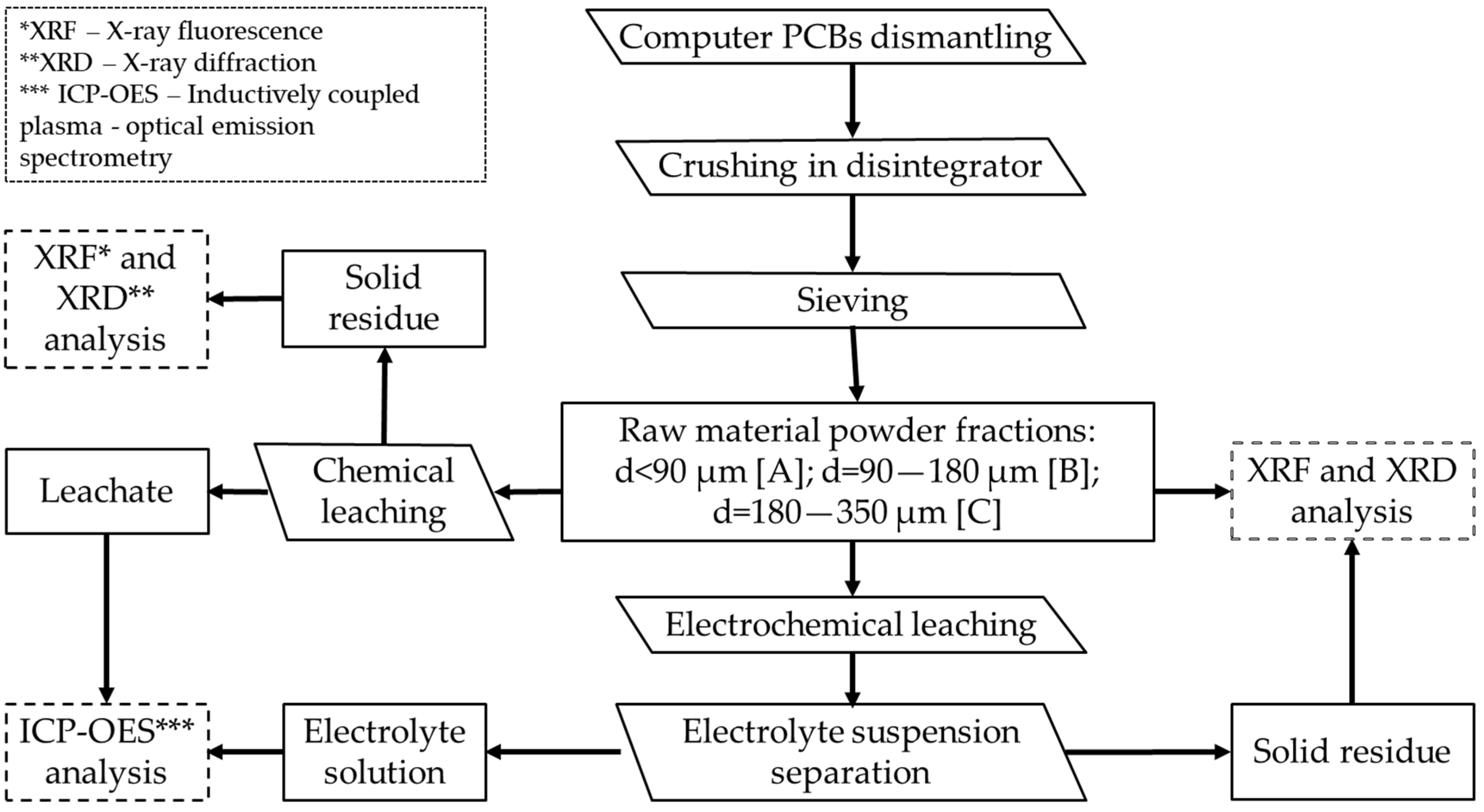
Abstract
1. Introduction
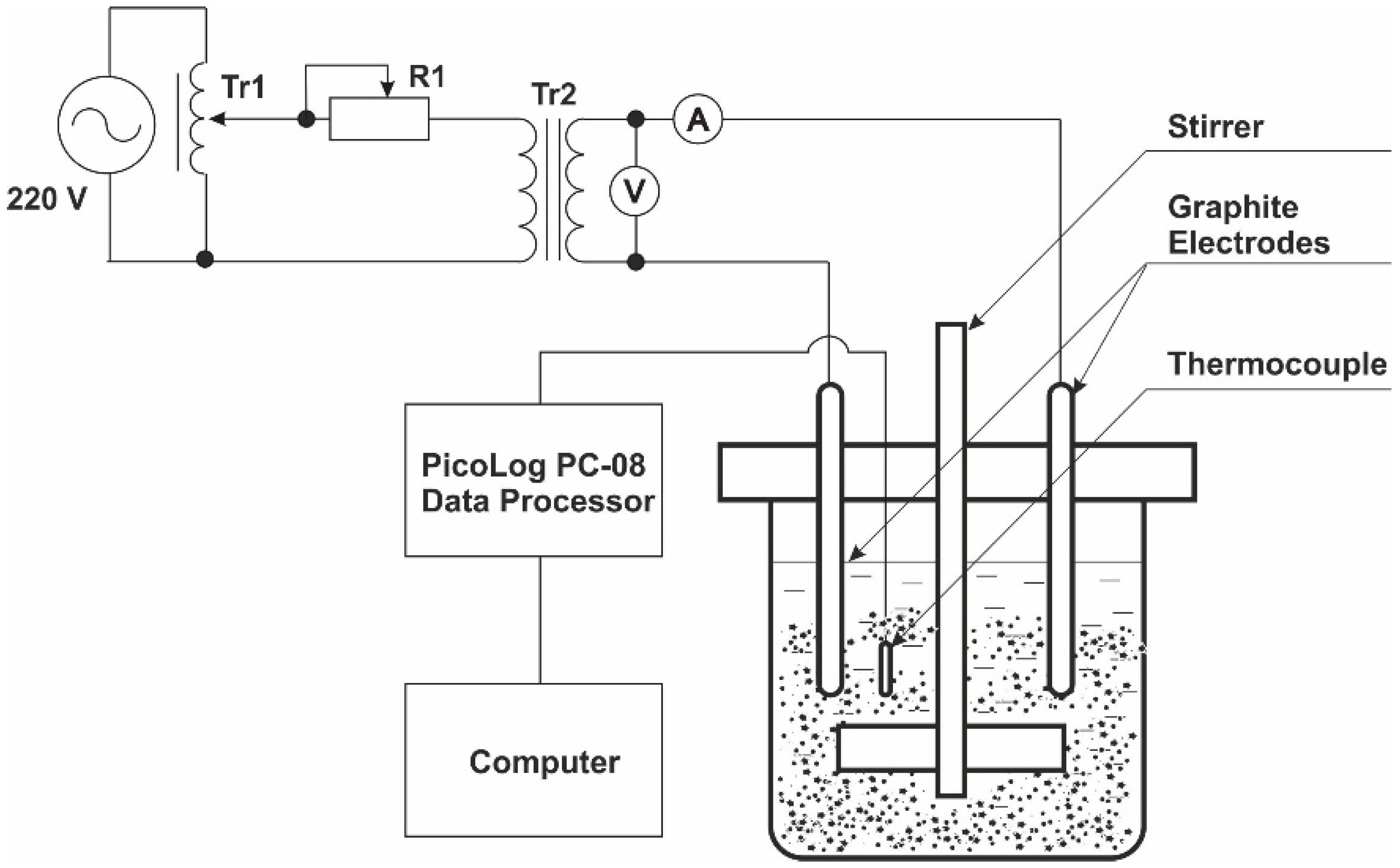
2. Materials and Methods
3. Results and Discussion
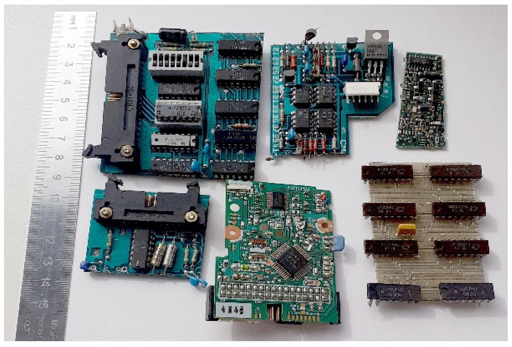
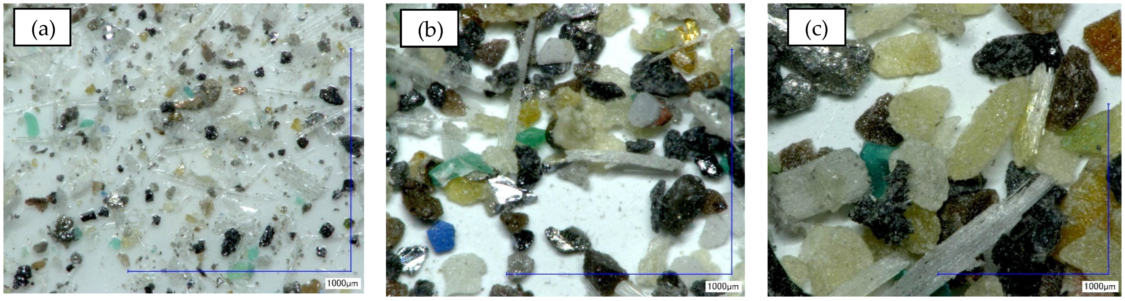
3.1. Raw Material Treatment and Characterisation
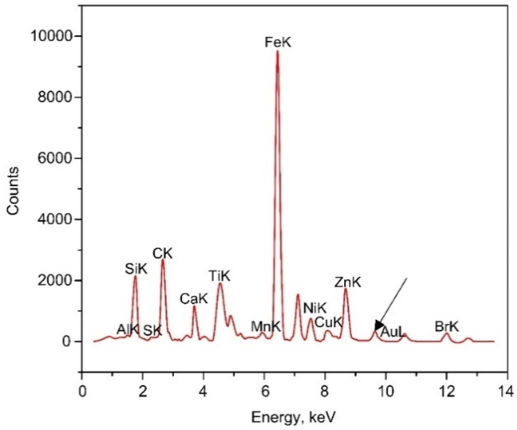
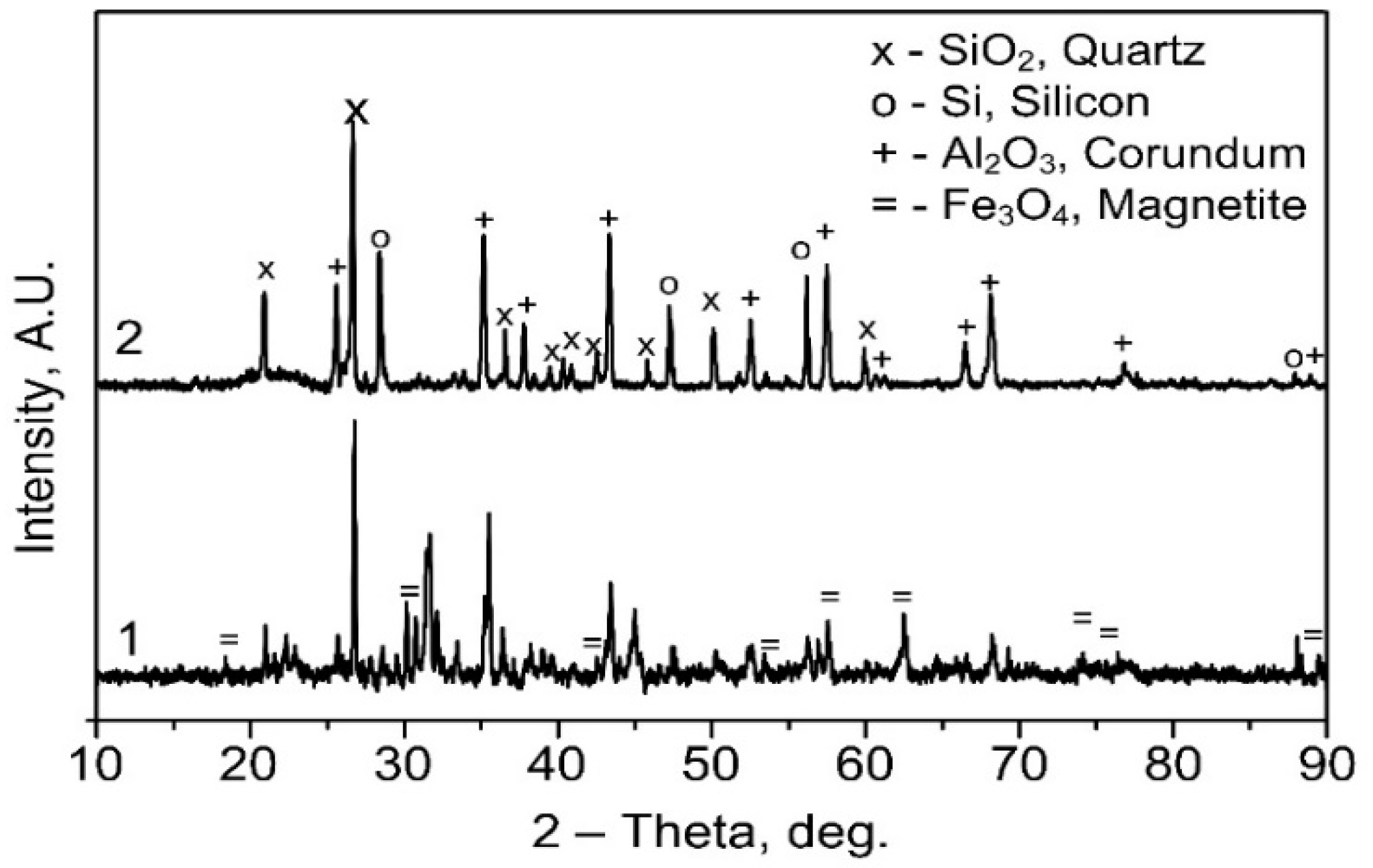
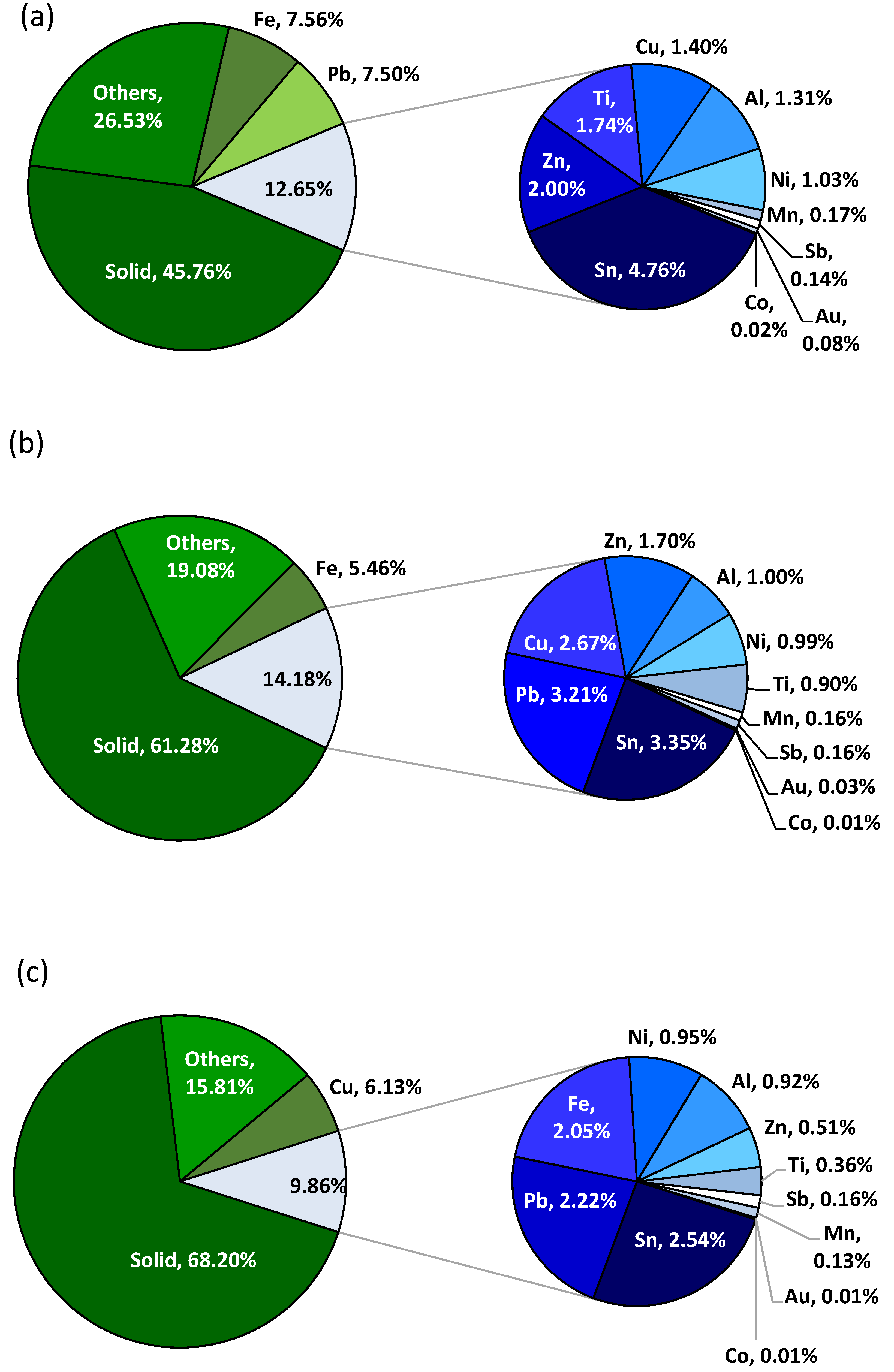
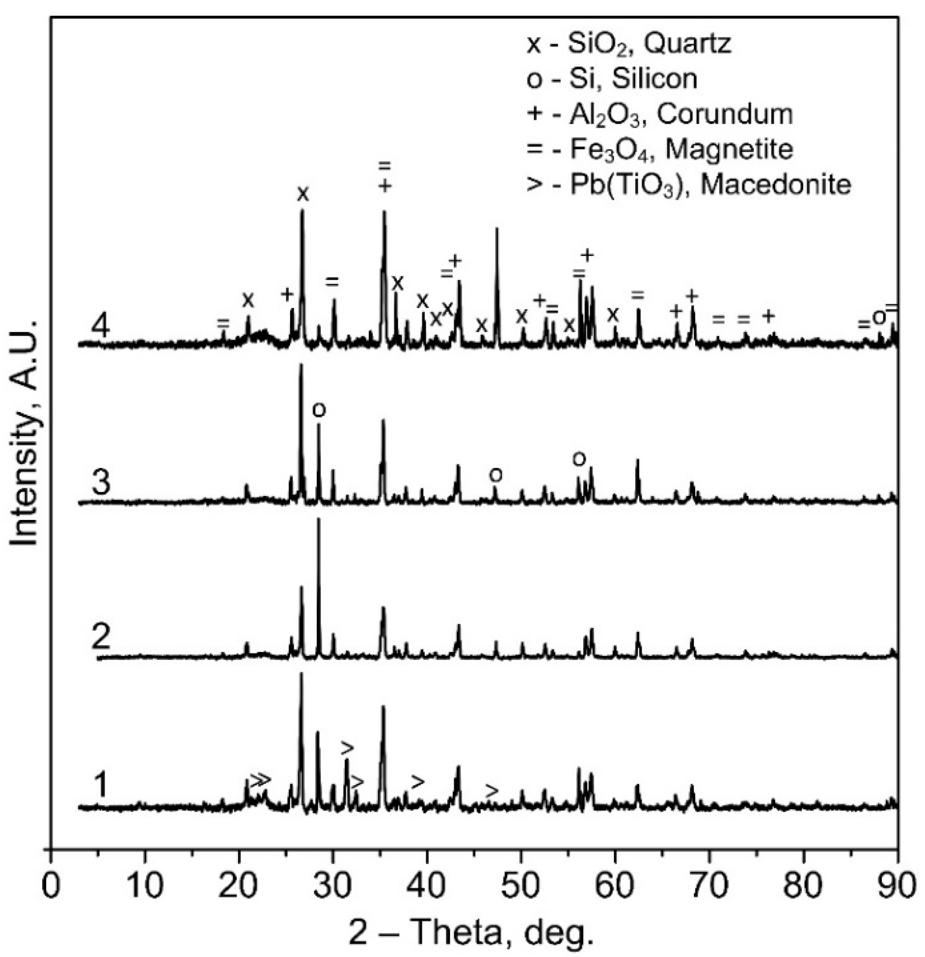
Complex Characterisation of Raw Material
3.2. Impact of Electrochemical Leaching Process Parameters on the Leaching Degree of Gold and Copper
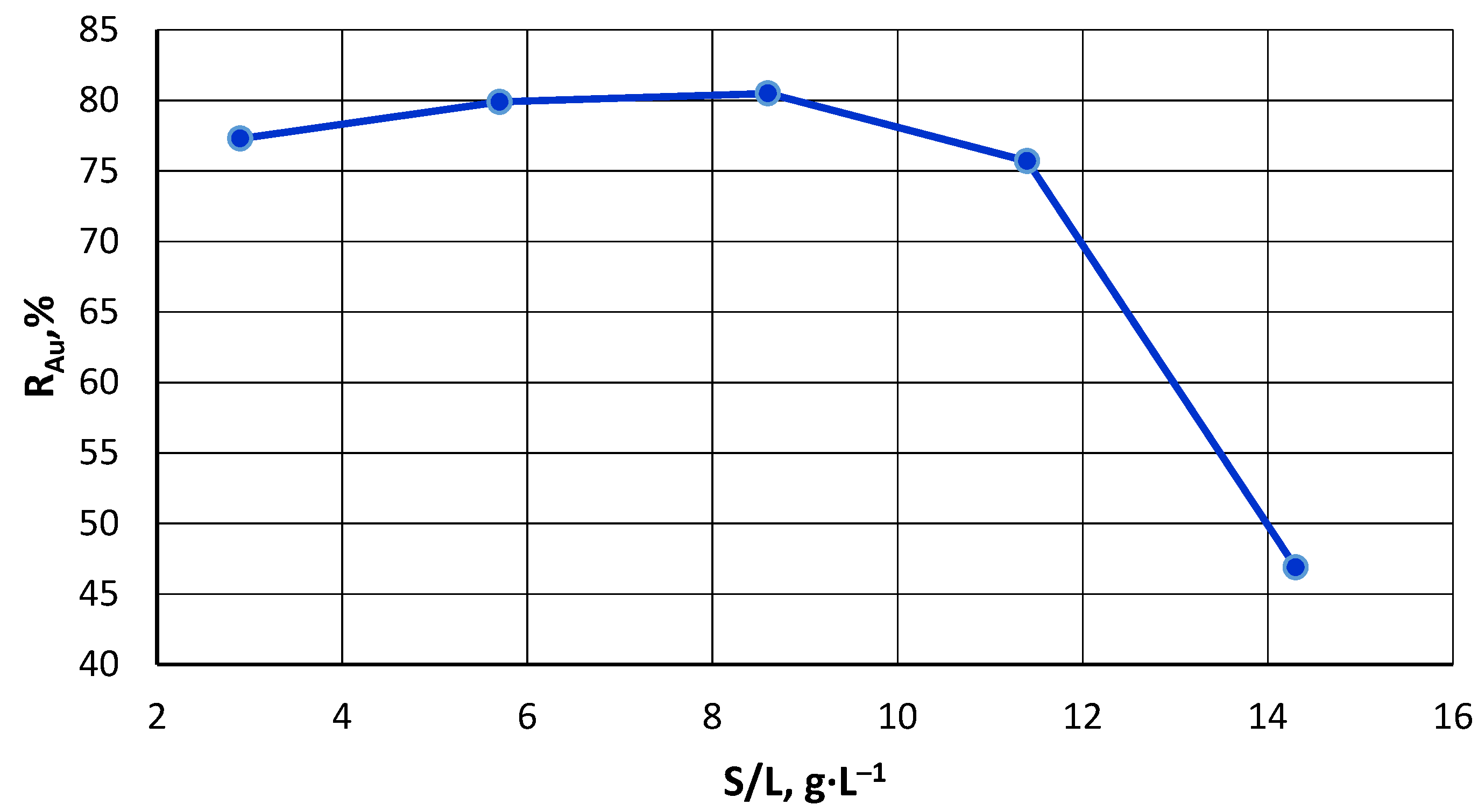
3.2.1. Solid/Liquid Ratio
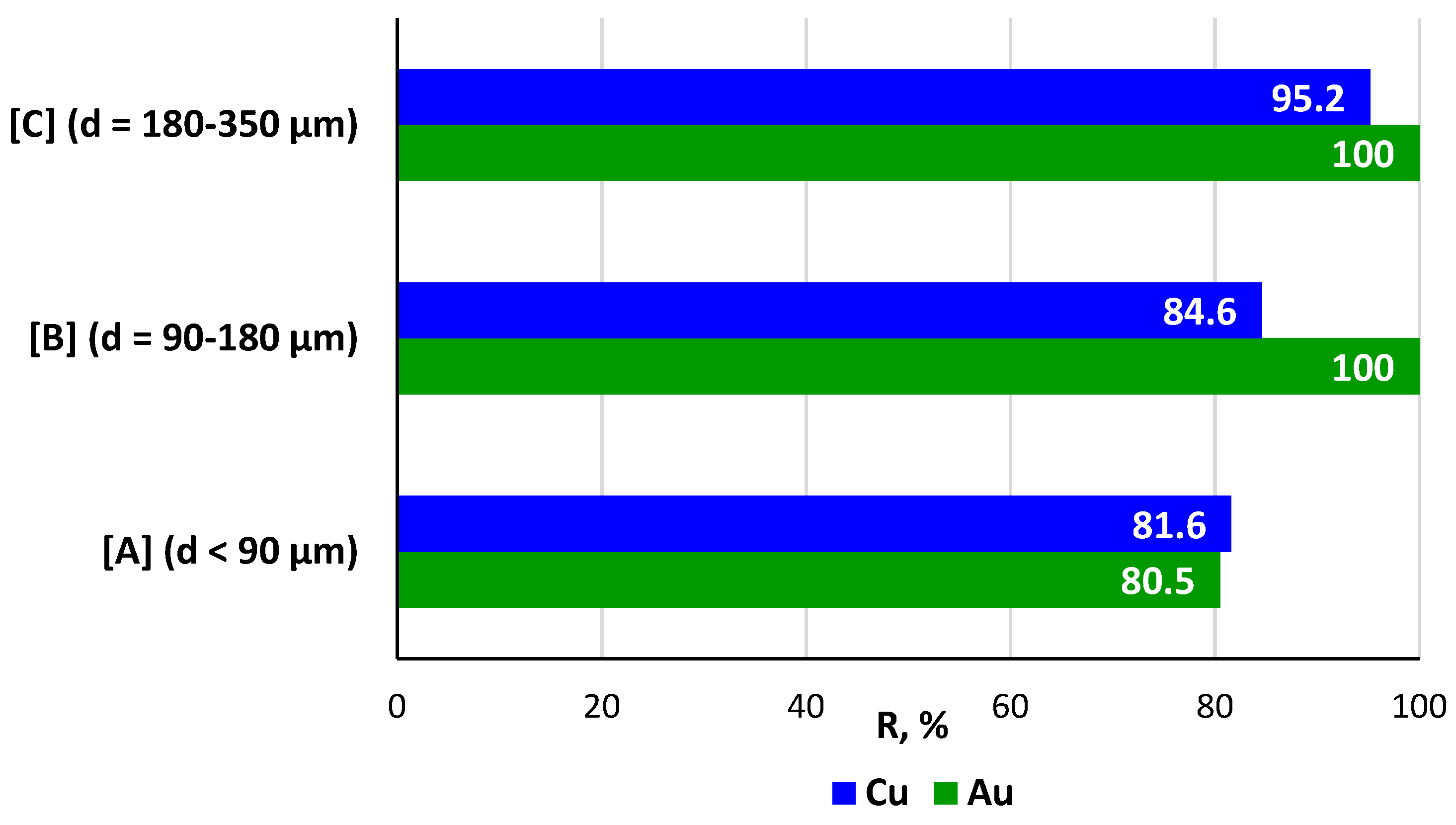
3.2.2. Raw Material Particle Size
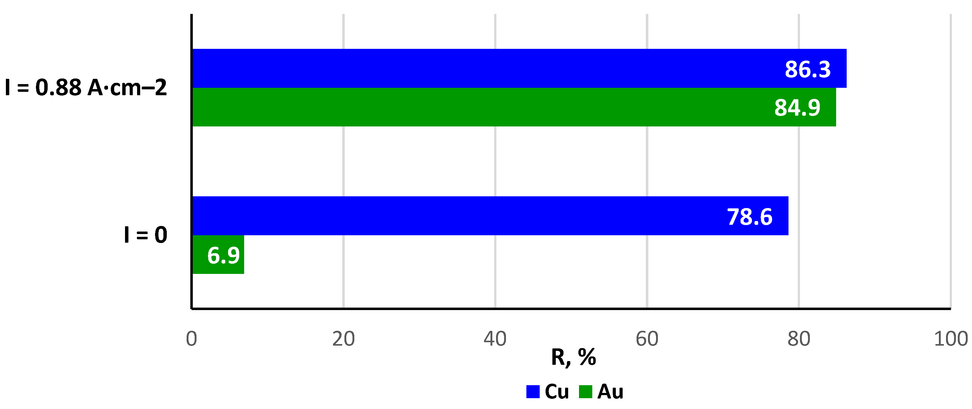
3.2.3. Alternating Current
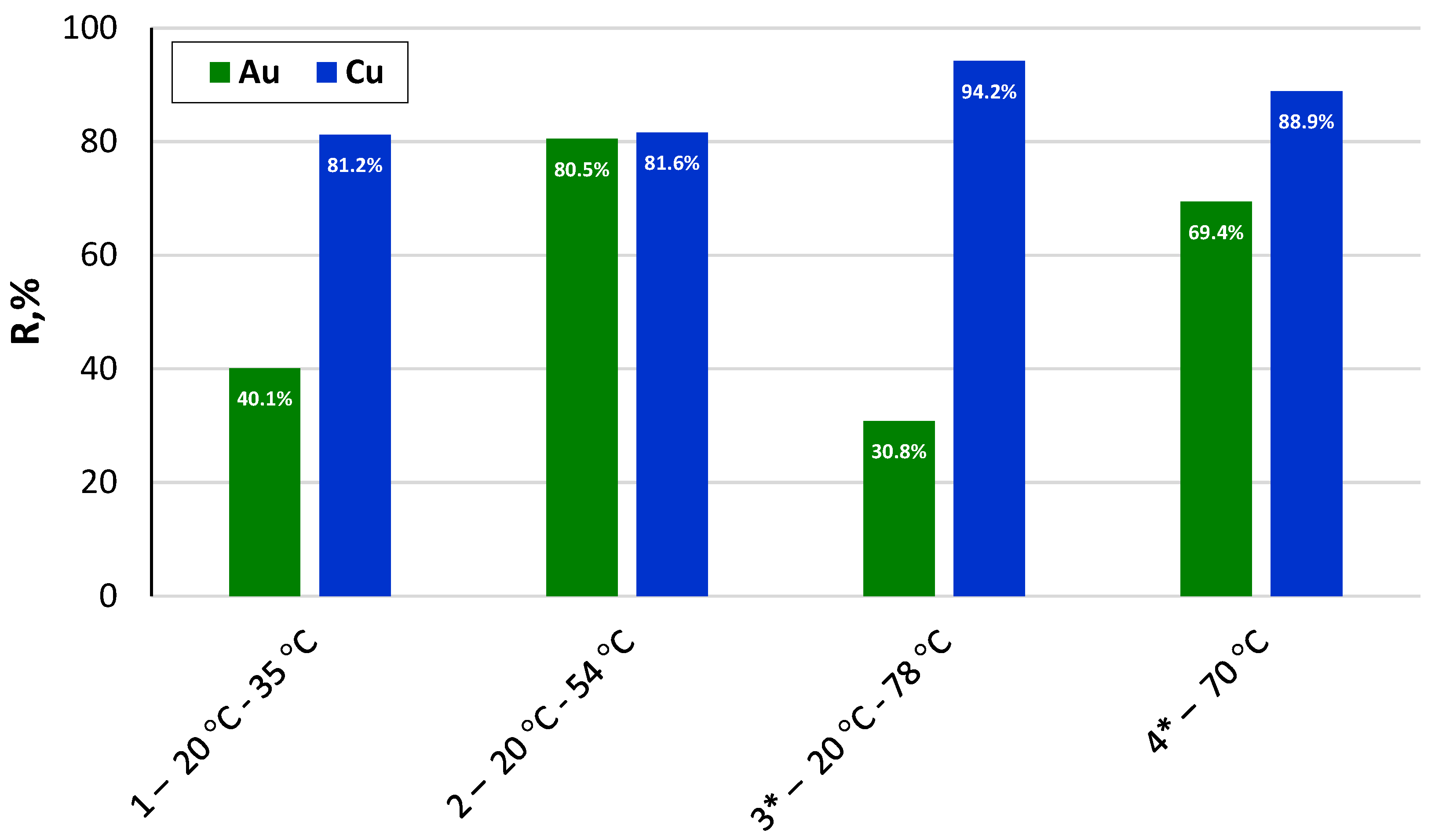
3.2.4. Electrolyte Temperature
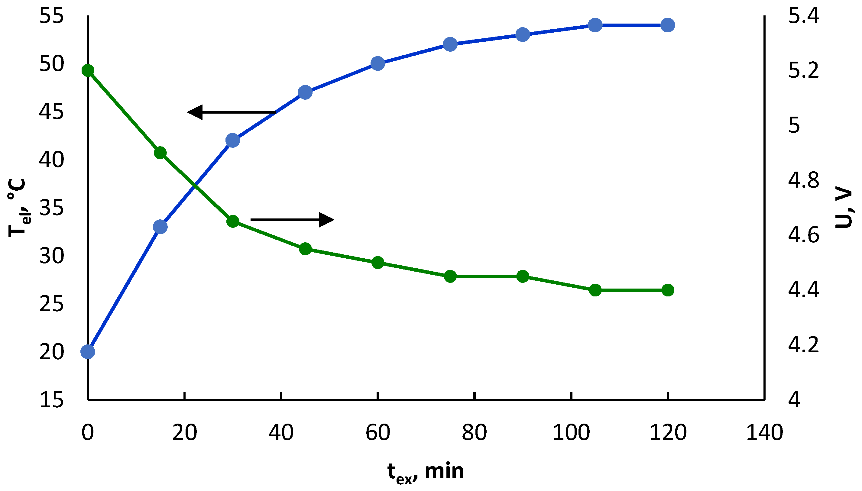
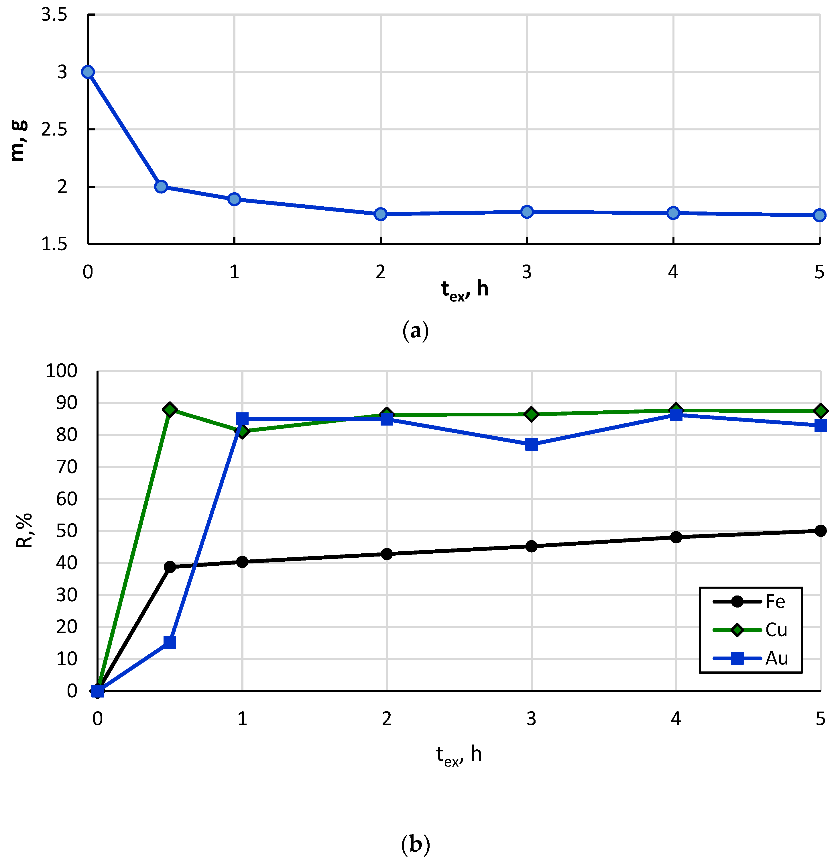
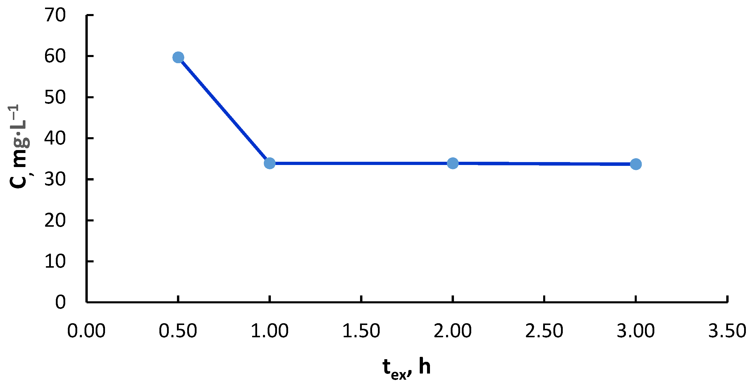
3.2.5. Experiment Duration
4. Conclusions
Author Contributions
Funding
Data Availability Statement
Acknowledgments
Conflicts of Interest
References
- Vidyadhar, A. A Review of Technology of Metal Recovery from Electronic Waste. In E-Waste in Transition—From Pollution to Resource; Intech: Rijeka, Croatia, 2016. [Google Scholar] [CrossRef]
- Paola, M. Recycling of Printed Circuit Boards. In Integrated Waste Management—Volume II; Intech: Rijeka, Croatia, 2011. [Google Scholar] [CrossRef]
- Bizzo, W.A.; Figueiredo, R.A.; De Andrade, V.F. Characterization of Printed Circuit Boards for Metal and Energy Recovery after Milling and Mechanical Separation. Materials 2014, 7, 4555–4566. [Google Scholar] [CrossRef] [PubMed]
- Gao, Z.; Li, J.; Zhang, H.-C. Printed circuit board recycling: A state-of-the-art survey. IEEE Trans. Electron. Packag. Manuf. 2004, 27, 33–42. [Google Scholar] [CrossRef]
- Van Yken, J.; Cheng, K.Y.; Boxall, N.J.; Sheedy, C.; Nikoloski, A.N.; Moheimani, N.R.; Kaksonen, A.H. A Comparison of Methods for the Characterisation of Waste-Printed Circuit Boards. Metals 2021, 11, 1935. [Google Scholar] [CrossRef]
- Xolo, L.; Moleko-Boyce, P.; Makelane, H.; Faleni, N.; Tshentu, Z. Status of recovery of strategic metals from spent secondary products. Minerals 2021, 11, 673. [Google Scholar] [CrossRef]
- Işıldar, A.; van de Vossenberg, J.; Rene, E.R.; van Hullebusch, E.D.; Lens, P.N. Two-step bioleaching of copper and gold from discarded printed circuit boards (PCB). Waste Manag. 2016, 57, 149–157. [Google Scholar] [CrossRef]
- Baniasadi, M.; Vakilchap, F.; Bahaloo-Horeh, N.; Mousavi, S.M.; Farnaud, S. Advances in bioleaching as a sustainable method for metal recovery from e-waste: A review. J. Ind. Eng. Chem. 2019, 76, 75–90. [Google Scholar] [CrossRef]
- Krishnan, S.; Zulkapli, N.S.; Kamyab, H.; Taib, S.M.; Din, M.F.B.M.; Majid, Z.A.; Chaiprapat, S.; Kenzo, I.; Ichikawa, Y.; Nasrullah, M.; et al. Current technologies for recovery of metals from industrial wastes: An overview. Environ. Technol. Innov. 2021, 22, 101525. [Google Scholar] [CrossRef]
- Zhou, H.-B.; Zeng, W.-M.; Yang, Z.-F.; Xie, Y.-J.; Qiu, G.-Z. Bioleaching of chalcopyrite concentrate by a moderately thermophilic culture in a stirred tank reactor. Bioresour. Technol. 2009, 100, 515–520. [Google Scholar] [CrossRef]
- Tuncuk, A.; Stazi, V.; Akcil, A.; Yazici, E.Y.; Deveci, H. Aqueous metal recovery techniques from e-scrap: Hydrometallurgy in recycling. Miner. Eng. 2012, 25, 28–37. [Google Scholar] [CrossRef]
- Zhang, L.; Xu, Z. A review of current progress of recycling technologies for metals from waste electrical and electronic equipment. J. Clean. Prod. 2016, 127, 19–36. [Google Scholar] [CrossRef]
- Feng, F.; Liu, J.; Zhao, M.; Yu, L.; Wang, H.; Lu, C.; Zhang, Q.; Zhao, J.; Sun, Y.; Cen, J.; et al. Study of an Environmentally Friendly Method for the Dissolution of Precious Metal with Ionic Liquid and Iodoalkane. Metals 2021, 11, 919. [Google Scholar] [CrossRef]
- Zhang, Y.; Liu, S.; Xie, H.; Zeng, X.; Li, J. Current Status on Leaching Precious Metals from Waste Printed Circuit Boards. Procedia Environ. Sci. 2012, 16, 560–568. [Google Scholar] [CrossRef]
- Akcil, A.; Erust, C.; Gahan, C.S.; Ozgun, M.; Sahin, M.; Tuncuk, A. Precious metal recovery from waste printed circuit boards using cyanide and non-cyanide lixiviants—A review. Waste Manag. 2015, 45, 258–271. [Google Scholar] [CrossRef] [PubMed]
- Birich, A.; Stopic, S.; Friedrich, B. Kinetic Investigation and Dissolution Behavior of Cyanide Alternative Gold Leaching Reagents. Sci. Rep. 2019, 9, 1–10. [Google Scholar] [CrossRef]
- Shah, M.B.; Tipre, D.; Dave, S.R. Chemical and biological processes for multi-metal extraction from waste printed circuit boards of computers and mobile phones. Waste Manag. Res. J. A Sustain. Circ. Econ. 2014, 32, 1134–1141. [Google Scholar] [CrossRef] [PubMed]
- Masavetas, I. Production of copper powder form printed circuit boards by electrodeposition. Glob. Nest J. 2009, 11, 241–247. [Google Scholar] [CrossRef]
- Ghorbani, Y.; Franzidis, J.-P.; Petersen, J. Heap leaching technology-current state, innovations and future directions: A review. Miner. Process. Extr. Met. Rev. 2016, 37, 73–119. [Google Scholar] [CrossRef]
- Zhou, Q.F.; Zhu, W. Recovery of gold from waste computer and its accessories. China Resources Comprehensive Utilization. China Resour. Compr. Util. 2003, 7, 31–35. [Google Scholar]
- Mineev, G.G.; Panchenko, A.F. Solvents of gold and silver in hydrometallurgy; Metallurgy: Moscow, Russia, 1994; p. 244. [Google Scholar]
- Seisko, S.; Lampinen, M.; Aromaa, J.; Laari, A.; Koiranen, T.; Lundström, M. Kinetics and mechanisms of gold dissolution by ferric chloride leaching. Miner. Eng. 2018, 115, 131–141. [Google Scholar] [CrossRef]
- Filmer, A.O.; Lawrence, P.R.; Hoffmann, W. Comparison Of Cyanide, Thiourea And Chlorine As Lixiviants For Gold. In Symposia Series—Australasian Institute of Mining and Metallurgy; Australasian Institute of Mining and Metallurgy: Melbourne, VIC, Australia, 1984; pp. 279–287. [Google Scholar]
- Sahin, M.; Akcil, A.; Erust, C.; Altynbek, S.; Gahan, C.S.; Tuncuk, A. A Potential Alternative for Precious Metal Recovery from E-waste: Iodine Leaching. Sep. Sci. Technol. 2015, 50, 2587–2595. [Google Scholar] [CrossRef]
- Diaz, M.; Kelsall, G.; Welham, N. Electrowinning coupled to gold leaching by electrogenerated chlorine. J. Electroanal. Chem. 1993, 361, 25–38. [Google Scholar] [CrossRef]
- Winand, R. Chloride hydrometallurgy. Hydrometallurgy 1991, 27, 285–316. [Google Scholar] [CrossRef]
- Kim, E.-Y.; Kim, M.-S.; Lee, J.-C.; Jeong, J.; Pandey, B. Leaching kinetics of copper from waste printed circuit boards by electro-generated chlorine in HCl solution. Hydrometallurgy 2011, 107, 124–132. [Google Scholar] [CrossRef]
- Kim, E.-Y.; Kim, M.-S.; Lee, J.-C.; Jha, M.K.; Yoo, K.; Jeong, J. Effect of cuprous ions on Cu leaching in the recycling of waste PCBs, using electro-generated chlorine in hydrochloric acid solution. Miner. Eng. 2008, 21, 121–128. [Google Scholar] [CrossRef]
- Pilone, D.; Kelsall, G. Metal Recovery from Electronic Scrap by Leaching and Electrowinning IV. Miner. Eng. 2003, 2, 1565–1575. [Google Scholar] [CrossRef]
- Kim, M.-S.; Lee, J.-C.; Park, S.-W.; Jeong, J.; Kumar, V. Dissolution behaviour of platinum by electro-generated chlorine in hydrochloric acid solution. J. Chem. Technol. Biotechnol. 2013, 88, 1212–1219. [Google Scholar] [CrossRef]
- Kim, E.-Y.; Kim, M.-S.; Lee, J.-C.; Pandey, B. Selective recovery of gold from waste mobile phone PCBs by hydrometallurgical process. J. Hazard. Mater. 2011, 198, 206–215. [Google Scholar] [CrossRef]
- Ilyas, S.; Srivastava, R.R.; Kim, H. Gold recovery from secondary waste of PCBs by electro-Cl2 leaching in brine solution and solvo-chemical separation with tri-butyl phosphate. J. Clean. Prod. 2021, 295, 126389. [Google Scholar] [CrossRef]
- Lister, T.E.; Wang, P.; Anderko, A. Recovery of critical and value metals from mobile electronics enabled by electrochemical processing. Hydrometallurgy 2014, 149, 228–237. [Google Scholar] [CrossRef]
- Shulgin, L.P. Overvoltage of electrode reactions in solutions during the passage of a symmetrical alternative current. J. Phys. Chem. 1979, 3, 2048–2051. (In Russian) [Google Scholar]
- Styrkas, A.; Styrkas, D. Electrochemical dissolution of metals of the platinum group by alternating current. J. Appl. Electrochem. 1995, 25, 490–494. [Google Scholar] [CrossRef]
- Box, W.D. Dissolution of Metals by AC Electrolysis. Nucl. Appl. 1966, 2, 299–303. [Google Scholar] [CrossRef]
- Alabyshev, A.F.; Vyacheslavov, P.M.; Galnbek, A.A.; Zhivotinsky, P.B.; Rotinyan, A.L.; Fedotiev, N.P. Applied Electrochemistry; Khimija: Lningrad, Russia, 1974. (In Russian) [Google Scholar]
- Taras, M. The Micro-Titration of Free Chlorine With Methyl Orange. J. Am. Water Work. Assoc. 1946, 38, 1146–1150. [Google Scholar] [CrossRef]
- Zimakov, S.; Goljandin, D.; Peetsalu, P.; Kulu, P. Metallic powders produced by the disintegrator technology. Int. J. Mater. Prod. Technol. 2007, 28, 226. [Google Scholar] [CrossRef]
- Peetsalu, P.; Goljandin, D.; Kulu, P.; Mikli, V. Micropowders Producted By Disintegrator Milling. Powder Metall. 2003, 3, 99–110. [Google Scholar]
- Goljandin, D.; Sarjas, H.; Kulu, P.; Käerdi, H.; Mikli, V. Metal-Matrix Hardmetal/Cermet Reinforced Composite Powders for Thermal Spray. Mater. Sci. 2012, 18, 84–89. [Google Scholar] [CrossRef]
- Blumbergs, E.; Serga, V.; Shishkin, A.; Goljandin, D.; Shishko, A.; Zemcenkovs, V.; Markus, K.; Baronins, J.; Pankratov, V. Selective Disintegration–Milling to Obtain Metal-Rich Particle Fractions from E-Waste. Metals 2022, 12, 1468. [Google Scholar] [CrossRef]
- Xian, Y.; Tao, Y.; Ma, F.; Zhou, Y. Recovery of Metals from Heat-Treated Printed Circuit Boards via an Enhanced Gravity Concentrator and High-Gradient Magnetic Separator. Materials 2021, 14, 4566. [Google Scholar] [CrossRef]
- Mazanko, A.F. Industrial Membrane Electrolysis; Chemistry: Moscow, Russia, 1989; p. 240. [Google Scholar]
- Oliveira, P.C.; Taborda, F.C.; Nogueira, C.A.; Margarido, F. The Effect of Shredding and Particle Size in Physical and Chemical Processing of Printed Circuit Boards Waste. Mater. Sci. Forum 2012, 730–732, 653–658. [Google Scholar]
- Podchainova, V.N.; Simonova, L.N. Analytical Chemistry of the Elements. The Cooper; Nauka: Moscow, Russia, 1990; p. 279. (In Russian) [Google Scholar]
- Bryce, C.; Berk, D. Kinetics of the dissolution of copper in iron(III) chloride solutions. Ind. Eng. Chem. Res. 1995, 34, 1412–1418. [Google Scholar] [CrossRef]
- Alkan, M.; Oktay, M.; Kocakerim, M.; Copur, M. Solubility of chlorine in aqueous hydrochloric acid solutions. J. Hazard. Mater. 2005, 119, 13–18. [Google Scholar] [CrossRef] [PubMed]


Publisher’s Note: MDPI stays neutral with regard to jurisdictional claims in published maps and institutional affiliations. |
© 2022 by the authors. Licensee MDPI, Basel, Switzerland. This article is an open access article distributed under the terms and conditions of the Creative Commons Attribution (CC BY) license (https://creativecommons.org/licenses/by/4.0/).
Share and Cite
Serga, V.; Zarkov, A.; Blumbergs, E.; Shishkin, A.; Baronins, J.; Elsts, E.; Pankratov, V. Leaching of Gold and Copper from Printed Circuit Boards under the Alternating Current Action in Hydrochloric Acid Electrolytes. Metals 2022, 12, 1953. https://doi.org/10.3390/met12111953
Serga V, Zarkov A, Blumbergs E, Shishkin A, Baronins J, Elsts E, Pankratov V. Leaching of Gold and Copper from Printed Circuit Boards under the Alternating Current Action in Hydrochloric Acid Electrolytes. Metals. 2022; 12(11):1953. https://doi.org/10.3390/met12111953
Chicago/Turabian StyleSerga, Vera, Aleksej Zarkov, Ervins Blumbergs, Andrei Shishkin, Janis Baronins, Edgars Elsts, and Vladimir Pankratov. 2022. "Leaching of Gold and Copper from Printed Circuit Boards under the Alternating Current Action in Hydrochloric Acid Electrolytes" Metals 12, no. 11: 1953. https://doi.org/10.3390/met12111953
APA StyleSerga, V., Zarkov, A., Blumbergs, E., Shishkin, A., Baronins, J., Elsts, E., & Pankratov, V. (2022). Leaching of Gold and Copper from Printed Circuit Boards under the Alternating Current Action in Hydrochloric Acid Electrolytes. Metals, 12(11), 1953. https://doi.org/10.3390/met12111953