Article

Experimental Investigation of Thrust Force in the Drilling of Titanium Alloy Using Different Machining Techniques

1
School of Mechanical and Electrical Engineering, Henan Institute of Science and Technology, Xinxiang 453003, China
2
School of Mechanical and Electrical Engineering, Tangshan University, Tangshan 063000, China
*
Author to whom correspondence should be addressed.
Metals 2022, 12(11), 1905; https://doi.org/10.3390/met12111905
Submission received: 4 October 2022 / Revised: 29 October 2022 / Accepted: 3 November 2022 / Published: 7 November 2022
(This article belongs to the Special Issue Advanced Metal Cutting Technology and Tools)

Abstract

:
Titanium alloy is a kind of hard-to-cut material widely used in aerospace, military and medical fields, and mechanical drilling is the primary technique used for hole-making in titanium alloy materials. The drilling force is an inevitable concomitant phenomenon in the drilling process and thrust force is its most important component. During the drilling of titanium alloy, it is crucial to understand the fundamental characteristics and changing rules of thrust force for optimizing process parameters, improving machining quality and predicting tool failure. In this paper, four different techniques, such as direct drilling (DD), ultrasonic vibration drilling (UVD), peck drilling (PD) and ultrasonic vibration peck drilling (UVPD), were used to drill small holes into Ti-6Al-4V titanium alloy, the thrust force was measured and its mean, maximum and peak-to-valley value were acquired from the time-domain waveform. Then the time-domain and frequency-domain characteristics of thrust force under the four techniques were compared, and the changing rules of thrust force with vibration amplitudes during UVD and UVPD were investigated. The results showed that, when compared to DD, UVD decreased the mean thrust force Famean by about 18.6%, and the force reduction effect was more significant as the amplitude increased. The variable velocity cutting characteristics and the antifriction effect of UVD were the primary reasons for the reduction of Famean. The pecking motion and ultrasonic vibration had a synergistic effect on reducing thrust force; UVPD could simultaneously reduce the mean thrust force Famean and maximum thrust force Famax. When the amplitude A was chosen within the range of 2–3 μm, Famax and Famean were reduced by approximately 37% and 40% in comparison to DD.

1. Introduction

Titanium alloy is an excellent light alloy with a high specific strength, large specific toughness, good thermal stability and high corrosion resistance, etc. Therefore, it has a wide range of applications in aerospace, military and medical equipment [1,2,3]. However, titanium alloy is also a typically hard-to-cut material due to its poor thermal conductivity, high chemical activity and low modulus of elasticity, which results in some undesirable cutting performances, such as a high cutting temperature, large specific cutting force, high work hardening tendency, low tool life and poor machining accuracy. Therefore, the precision cutting of titanium alloy has always been one of the research highlights in the field of advanced machining [4,5].
Mechanical drilling is a common cutting technology that is widely used in making various holes for assembly or connecting. To meet the different requirements of hole-making, various drilling techniques, such as direct drilling (DD), peck drilling (PD), and vibration drilling (VD) can be applied. However, no matter which drilling technique is used, the drilling force is always an unavoidable byproduct restricting the improvement of machining quality and the reduction of production costs. Thrust force is a significant component of the drilling force; a large thrust force often reduces machining accuracy and surface quality [6,7], shortens tool life [8], increases the burr dimension of the hole edge [9] and even leads to delamination of laminated materials [10,11]. As a result, drilling force, particularly thrust force, is always a key research target of drilling titanium alloy.
Direct drilling (DD) is a long-established continuous hole-making technique that is still widely used in mechanical manufacturing. Kim [12] investigated the effect of cutting parameters on thrust force during DD of titanium alloys, and the results revealed that the thrust force increased with the feed rate and decreased with the spindle speed, but the feed rate was a more significant influencing factor. Li [13] discovered that the material and geometry of drill bit were also important influencing factors of drilling force during the DD of titanium alloys, with the WC-Co twist drill achieving a lower drilling force than the HSS twist drill and the flat drill being more conducive to reducing thrust force than the twist drill. Wei [14] found that, when DD of titanium/CFRP stack materials was performed, thrust forces had a significant impact on the inner surface quality, and the maximum thrust force usually appeared at the junction interface of titanium alloys and CFRP, which frequently resulted in delamination defects. Park [15] investigated the change of thrust force during DD of CFRP/titanium stack materials, and the results showed that the thrust force of carbide twist drill increased faster with the number of machined holes at high speeds than at low speeds, whereas the thrust force of the PCD twist drill did not change significantly with the hole number.
Peck drilling (PD) is a common method of drilling hard-to-cut material and creating deep holes; it converts the continuous cutting mode of DD to an intermittent cutting mode by the periodic retreat of the drill bit. Therefore, PD has superior chip-breakage, chip-removal, cooling and lubricating capabilities. Eltaggaz [16] carried out a comparative study of DD and PD of Ti-6Al-4V titanium alloy, and the results showed that PD had advantages in suppressing flank wear and burr formation because it had less thrust force and torque. Kuo [17] conducted the PD experiments of Ti-6Al-4V/CFRP/Al7050 stack materials and found that the drilling strategy (DD or PD) had a moderate effect on the average hole cylindricity. According to the research of Jiménez [18], the characteristic values of thrust force were very sensitive to drill wear during PD. Patra [19] discovered that the machined hole number could represent drill wear stages well during PD of AISI P20 tool steel and that the prediction of hole number for different cutting conditions using thrust force data indirectly revealed the tool wear status of drill bit. Kim [20] used thrust force to determine the proper pecking depth (also known as one-step feed length) for stable machining in deep-micro-hole peck drilling.
With the improvement of hole-making precision, vibration drilling (VD) has also been used to drill titanium alloy. VD is an advanced drilling technique derived from DD in which a single or composite vibration is superimposed on the workpiece or drill bit to change the drilling mechanism and improve the process effect. Based on vibration frequency, VD is classified into low-frequency vibration drilling (LFVD) and ultrasonic vibration drilling (UVD). Okamura [21] and Li [22] revealed that LFVD was conducive to reducing the drilling force. Churi [23,24] conducted the research of UVD for titanium alloy, and the results showed that ultrasonic vibration reduced the maximum drilling force by about 20%, and high rotation speed, low feed rate and medium ultrasonic power were more conducive to reducing the cutting force. Based on the drilling test of Ti6Al4V, Gao [25] indicated that, compared to DD, UVD could drop the mean thrust force by about 9.5–20.8%, and the feed rate and the ultrasonic amplitude played a significant role in the thrust force. On the basis of Churi’s research, Hsu [26] found that the thrust force could be further reduced by 3.2% by using the method of ultrasonic frequency tracking. The research of Jain [27] showed that, when ultrasonic vibration peck drilling (UVPD) of borosilicate glass was performed, vibration parameters were the main factors influencing the shape accuracy and edge damage of machined holes rather than the thrust force.
The above literature shows that the precision drilling of titanium alloy is one of research hotspots in the field of advanced machining, and the thrust force is an important influencing factor for drilling quality, tool life, dimensional accuracy and shape accuracy. DD, PD, UVD and UVPD are the main techniques for drilling titanium alloy. However, the changing rules of thrust force in UVD and UVPD are unclear, as is the action mechanism of ultrasonic vibration and pecking motion on thrust force, which limits the appropriate application of these techniques. In this paper, the drilling experiments of small holes for titanium alloy were carried out using the four techniques mentioned above, their thrust force characteristics were compared and analyzed, and the influence rules and reasons of ultrasonic amplitude on thrust force in UVD and UVPD were investigated. This study has a high reference value for the proper application of UVD and UVPD, as well as the precision drilling of titanium alloys.

2. Materials and Methods

2.1. Experimental Methods and Materials

As shown in Figure 1, the drilling experiments were carried out utilizing four techniques, including DD, PD, UVD and UVPD. The drilling force waveform was obtained by the Kistler dynamometer, and the mean, maximum and peak-to-valley values of thrust force were acquired from time-domain waveforms. Subsequently, the changing rules and causes of thrust force were investigated.
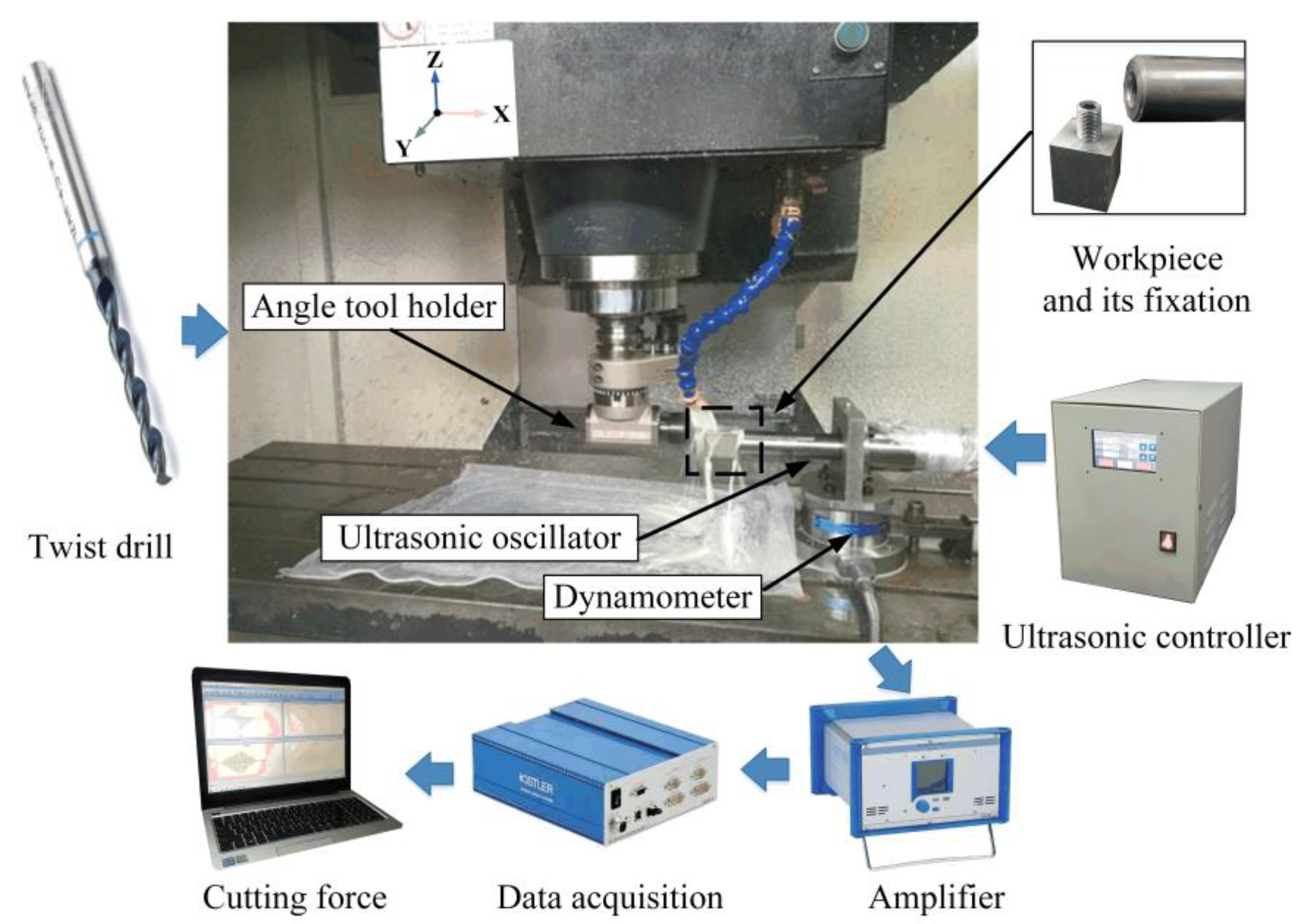
Figure 2 is the experimental setup, and the experiments were conducted on the JT-VL850B vertical machining center. The workpiece was fixed at the left end of the ultrasonic oscillator by a connecting bolt and driven to vibrate sinusoidally along the X axis. The vibration amplitude of the workpiece was adjusted by an ultrasonic controller. The vertical rotation of the spindle was changed to the horizontal rotation of the twist drill by using a 90° angle tool holder. The X-axis movement of the workbench was used to drill a blind hole with a diameter of Φ 3 mm and a depth of 10 mm. To facilitate the measurement of drilling force, the ultrasonic oscillator was fixed to the upper surface of a Kistler 9272 dynamometer and then clamped on the workbench of the machine tool. The drilling force data measured was magnified by the 5070A amplifier and collected by a 5697A acquisition instrument, and then sent to a computer for subsequent analysis. In this test, the sampling frequency of drilling force was 50,000Hz.
The workpiece material was Ti-6Al-4V titanium alloy and its size was 30 mm × 30 mm × 40 mm; its physical and mechanical properties are listed in Table 1. The cutting tool was the IZAR6000 high-speed steel twist drill made in Spain (Amorebieta, Spain), and its “diameter × total length × spiral flute length” was 3 mm × 50 mm × 19 mm. The drill with a point angle of 138o and an s-shaped spiral structure was coated with NITREX. The drilling lubrication mode was flood.

2.2. Test Parameters

The test parameters are shown in Table 2. The rotation speed n and feed per revolution fr (feed rate vf) were determined according to the recommendation of the tool manufacturer. Because the ultrasonic oscillator was designed based on the ultrasonic resonance principle, its output frequency f was fixed at 20 KHz and could not be adjusted, and the amplitude changing range was 0–5.5 μm. The pecking motion was realized by NC programming, and the pecking depth Q was chosen as 1 mm based on comprehensive consideration of the process effect and production efficiency, which means that it required 10 feed steps for drilling a 10 mm depth hole.

3. Results and Discussion

3.1. Comparison of Thrust Force under Different Drilling Techniques

3.1.1. Time-Domain Waveforms and Frequency Spectrum

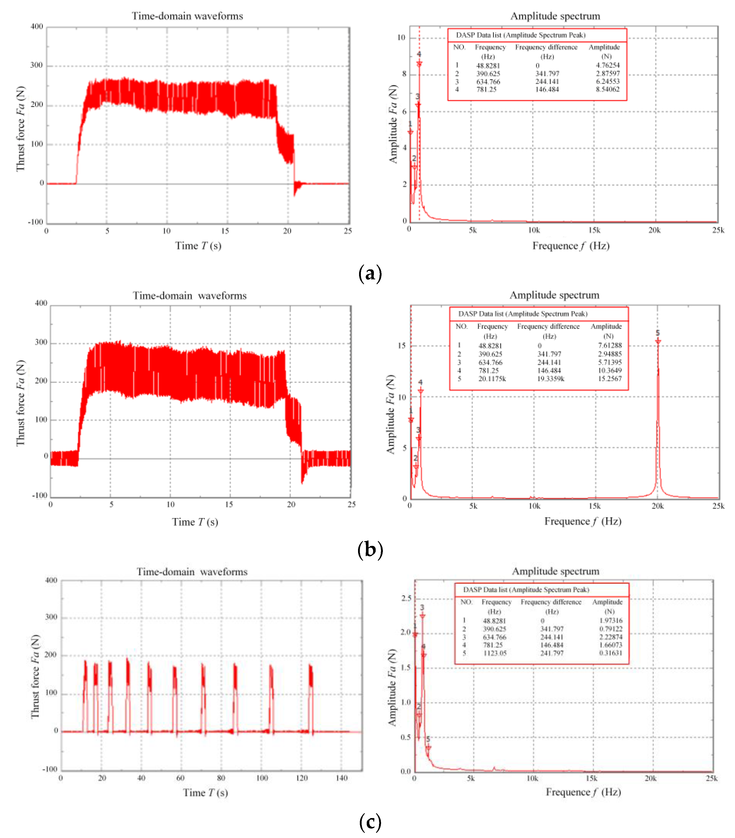
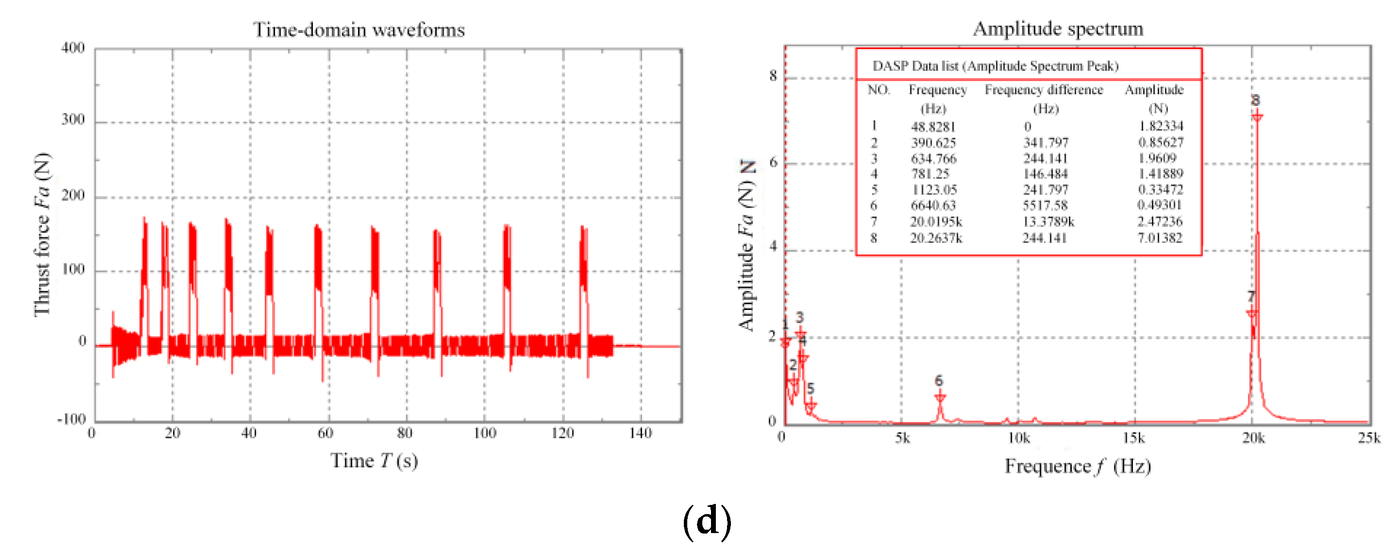
Figure 3 shows the time-domain waveforms and frequency spectrums of thrust force under different drilling techniques.
The time-domain waveforms show that: (1) Compared with non-peck drilling (DD and UVD), the machining time of PD and UVPD is longer due to the periodic retreat of the drill bit, and their time-domain waveforms include 10 feed steps. (2) With the same rotation speed and feed rate, the thrust forces of PD and UVPD are significantly lower than those of DD and UVD. The reason for this is that the effect of chip breakage, chip-removal, cooling and lubricating is better during PD and UVPD.
According to amplitude spectrums, (1) Compared with non-ultrasonic drilling (DD and PD), the frequency spectrum of UVD and UVPD includes 20 KHz spectral peak besides the 48.8281 Hz (cutting frequency) spectral peak and its harmonic waves (390.625, 634.766 and 781.25 Hz). The thrust force amplitude corresponding to 20 KHz is much larger than those of other frequencies, so the ultrasonic vibration had a significant effect on thrust force. (2) According to DASP data list, compared with non-peck drilling (DD and UVD), the frequency spectrums of PD and UVPD are more complex, which include the spectral peaks of 1123.05 Hz and 6640.63 Hz, but their thrust force amplitude is very low. This phenomenon indicates that the pecking motion is beneficial to reduce the fluctuation of thrust force.

3.1.2. Comparison of Characteristic Values of Thrust Force

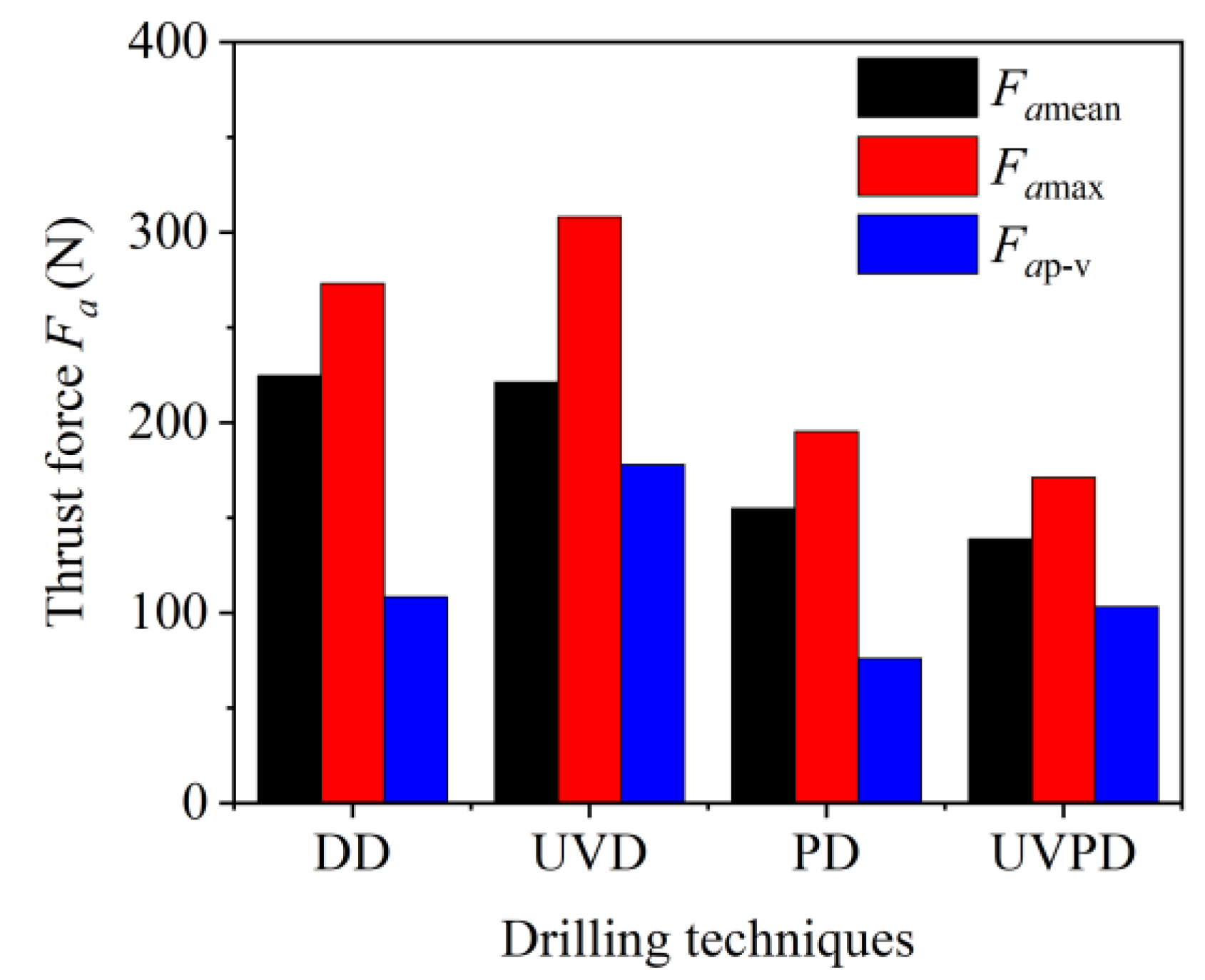
Figure 4 depicts the characteristic values of thrust force Fa under different drilling techniques, where Famean, Famax and Fap-v represent, respectively, the mean, maximum and peak-to-valley value of thrust force. These characteristic values were acquired from the time-domain waveform of the stable drill-in stage in Figure 3. To ensure data accuracy, the average value of five acquisitions in different wavebands was taken as the final result. According to Figure 4, (1) UVD has a higher Famax than the other three drilling techniques, which is related to the largest Fap-v caused by the repeated impact of ultrasonic vibration. (2) Whether assessed from Famean or Famax, PD and UVPD significantly reduces the thrust force when compared to non-peck drilling (DD and CVD). (3) Although the Fap-v of UVPD is higher than that of PD, its Famean and Famax are simultaneously decreased.
The aforementioned results demonstrate that, when drilling small holes in titanium alloy, UVD cannot replace PD, and the pecking motion and ultrasonic vibration work together to reduce thrust force in a synergistic way.

3.2. Effect of Vibration Amplitude on Thrust Force of UVD

3.2.1. Thrust Force at Various Amplitudes

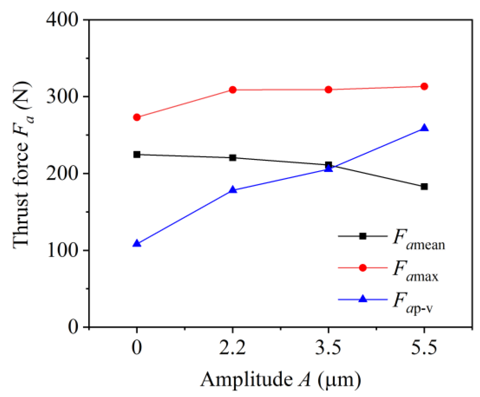
Figure 5 shows the thrust force of UVD at various amplitudes, with DD (A = 0 μm) considered as a special case of UVD. It can be seen from Figure 5 that: (1) The Fap-v of UVD is always greater than that of DD and increases almost proportionally with amplitude A. (2) The Famean of UVD is lower than that of DD, and it continued to fall with the increase in amplitude A. When the amplitude was increased from zero to 5.5 μm, the mean thrust force decreased from 224.7N to 182.9N, by 18.6%. (3) Although the Famax of UVD is higher than that of DD, it does not show an obvious variation with amplitude A. These findings demonstrate that ultrasonic vibration is conducive to reducing Famean and increasing Fap-v, as a result, the Famax will change accordingly.

3.2.2. Reasons for Thrust Force Changes in UVD

(1)
High-frequency impact effect of ultrasonic vibration
The direct influence of ultrasonic vibration on thrust force is its high-frequency impact action on the cutting area. The workpiece vibrated sinusoidally while feeding along the X axis during UVD, so its instantaneous vibration acceleration α can be derived from the displacement equation of standard sine vibration s = A sin ( 2 π f t ) .
α = 4 A π f 2 sin ( 2 π f t )
where A and f represent the amplitude and frequency of the ultrasonic vibration, respectively, and t is the working time of the ultrasonic oscillator. Here, the magnitude of vibration acceleration is proportional to amplitude A and the square of vibration frequency f.
When A = 2.2 μm and f = 20 KHz, the maximum vibration acceleration 4Af)2 is about equal to 3.47 × 10⁴ m/s2, and the vibration acceleration with high-frequency sine fluctuation will inevitably generate a large inertial impact force. Figure 6 shows the impact force Fi of ultrasonic vibration on the workpiece system without drilling. The impact force, with nearly 58 N amplitude, oscillates sinusoidally around the zero line at a frequency of 20 KHz. During the drilling, the cutting area was subjected to such impact action, which would undoubtedly result in an obvious increase in Fap-v. Because the vibration frequency f remained constant at 20 KHz, and the vibration acceleration had a linear relationship with amplitude A, the Fap-v increased almost proportionally with the rise in amplitude A.
(2)
Variable velocity cutting characteristic of UVD
The variable velocity cutting characteristic is one of the basic features of UVD, which results in the difference in chip deformation between UVD and DD. Because chip deformation is a primary source of the cutting force, the thrust force of UVD will change accordingly.
The ultrasonic vibration can cause a periodic variation in actual cutting velocity during UVD. As for the unit tool edge with distance r from the drill axis, the synthetic cutting velocity vr can be written as [28]:
v r = f r n + 2 π f A cos ( 2 π f t ) 2 + ( 2 π r n ) 2
where fr and n are the feed per revolution and the spindle speed, frn is the feed velocity of the drill tip relative to the workpiece, 2πfAcos(2πft) is the axial vibration velocity and 2πrn is the circumferential rotation velocity of unit tool edge.
When the outer edge point of the twist drill is chosen as the unit tool, r is equal to 1.5 mm. With the test conditions of n = 1200r/min, fr = 0.03 mm/min, f = 20 KHz, A = 5.5 μm, the feed velocity frn, the maximum axial vibration velocity 2πfA and circumferential rotation velocity 2πrn are 0.012, 41.5 and 11.3 m/min, respectively. The maximum axial vibration velocity is much greater than the feed velocity and more than three times the drill’s rotation velocity. In this case, ultrasonic vibration will result in a significant change in the actual cutting velocity, and the closer the unit tool edge is to the drill bit axis, the greater the influence of ultrasonic vibration. This high-frequency variable cutting velocity of UVD will cause a change in chip deformation and thrust force.
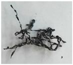
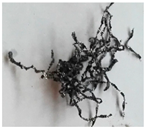
Figure 7 shows the chip morphology of DD and UVD. According to Figure 7, compared with DD, the chip curl extent of UVD was smaller and the curvature radius of each chip unit was larger, which indicates that UVD had a smaller chip deformation and less energy consumption. As a result, the drilling force would decrease.
(3)
Antifriction effect of UVD
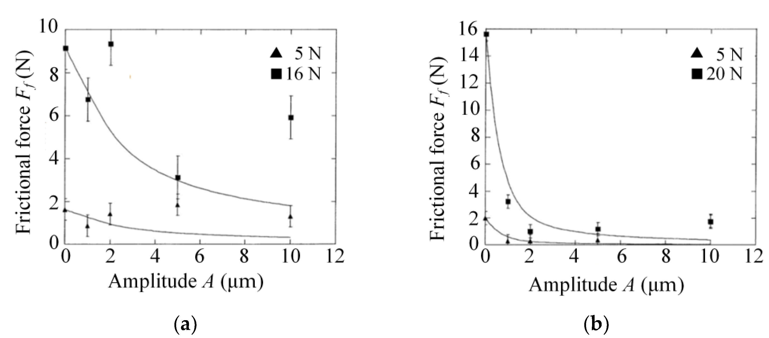
The third action of ultrasonic vibration on thrust force is that it can decrease the friction coefficient and the friction resistance between the drill bit, workpiece and chip. Many studies [29,30,31] found that the applied vibration plays an important role in lowering the average friction coefficient and frictional force of the sliding interface and the stick-slip interface, with the main reasons being the periodic separation between contact interfaces and the periodic transformation of friction vectors. Figure 8 shows the effect of ultrasonic vibration on frictional force Ff between sliding elements, Figure 8a,b depict two cases in which ultrasonic vibration is perpendicular to the sliding velocity and parallel to the sliding velocity, respectively. The symbols “▲” and “■” represent experimental results under different normal loads, and the curves represent experimental prediction trends. It can be seen from Figure 8 that the ultrasonic vibration can reduce the frictional force between sliding elements and the longitudinal vibration has a greater force reduction effect than the transverse vibration. Although the viscous friction is the primary mode of friction in the cutting deformation area, ultrasonic vibration is also conducive to decreasing the viscous friction area and effective friction coefficient [29].
In summary, the high-frequency impact effect of ultrasonic vibration is the direct cause of the Fap-v increasing proportionally with amplitude A, while the variable velocity cutting characteristics and the antifriction effect of UVD are the primary reasons for the reduction in Famean.

3.3. Effect of Vibration Amplitude on Thrust Force of UVPD

3.3.1. Thrust Force at Various Amplitudes

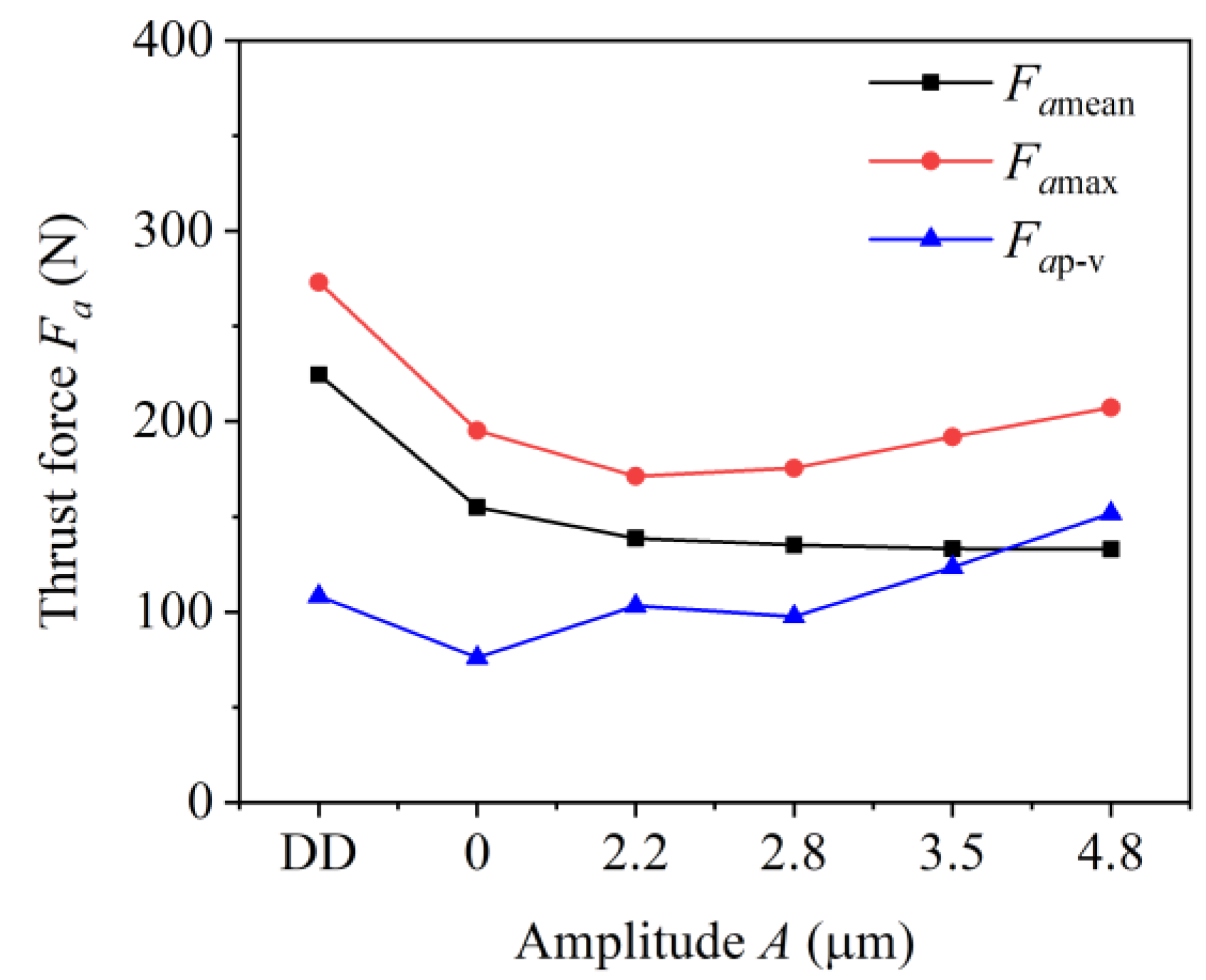
Figure 9 compares the thrust force of UVPD and DD at various amplitudes, where the PD (A = 0 μm) is considered as a special case of UVPD. According to Figure 9, (1) The Fap-v of PD is less than that of DD, and the Fap-v of UVPD gradually rises as the amplitude A increases. However, due to the influence of the pecking motion, this rise did not show an obvious linear trend. (2) The Famean of UVPD is significantly smaller than that of DD, and it continues to drop to 133N with the increase in amplitude A. The Famean was reduced by up to 40% compared with DD. This further confirmed that the pecking motion and ultrasonic vibration work synergistically to reduce Famean. (3) The Famax of UVPD is smaller than that of DD, and it decreases first and then increases as the amplitude A increases. Hence the smaller amplitude is more conducive to lowering the Famax, which was reduced by approximately 37%. Thus, in this experiment, the amplitude A should be chosen within the range of 2–3 μm.

3.3.2. Reasons for Reducing Thrust Force by UVPD

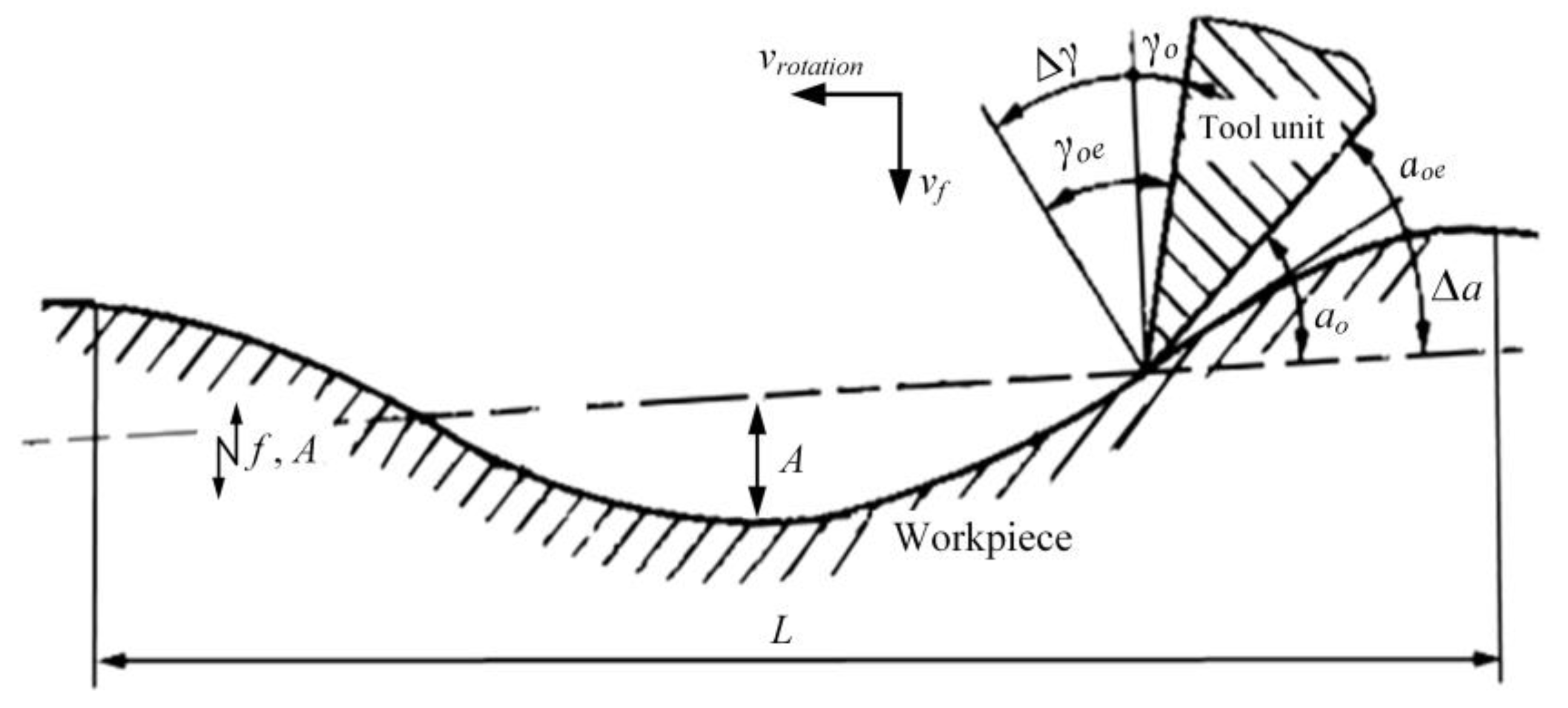
The frequency-to-rotation speed ratio f/n is an important parameter for the kinematics analysis of vibration drilling [32]. When n = 1200 r/min and f = 20 KHz, f/n equals 1000, indicating that the drill bit performs sinusoidal vibration 1000 times when rotating a circle relative to the workpiece. Figure 10 is a schematic diagram of sinusoidal vibration drilling, in which the drill vibrates sinusoidally with vibration frequency f and amplitude A, and vrotation and vf represent the rotation velocity and the feed rate, respectively. The sinusoidal curve depicts the ideal cutting route of a tool unit and the periodic cutting length L represents the circumferential cutting length in a vibration cycle. When a hole with a diameter of 3 mm is drilled at n = 1200 r/min and f = 20 KHz, the periodic cutting length at the drill outer edge point L = πD/(f/n) = 9.42 μm, which is in the same order as the amplitude A at the micron level. In this case, it is impossible for a millimeter-scale tool to cut out a micrometer-level sinusoidal curve due to the limitations of the tool structure and working angle. On the other hand, because of the design principle, the existing equipment of UVD can hardly adjust vibration frequency accurately, so UVD does not have the geometric chip-breaking characteristic that is similar to low-frequency vibration drilling [33,34]. However, UVPD has the external conditions for geometric chip-breaking owing to the periodic retreat of the drill bit.
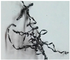
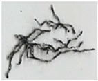
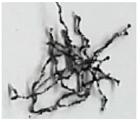
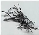
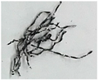
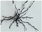
Table 3 compares the chip morphology of UVD and UVPD. According to Table 3, regardless of the amplitude, UVD always produces a continuous ribbon chip that often twined around the drill bit and rotated together until it was thrown off, while UVPD can achieve appropriate chip length by varying the pecking depth Q.
In other words, when UVD of titanium alloy is performed, it is easy to generate continuous ribbon chips, which increases the chip-removal resistance. UVPD can obtain the expected chip length, and the chip is removed smoothly. Furthermore, in terms of UVPD, the periodic retreat of the drill bit also makes it easier for the cutting fluid to enter the hole and reach the cutting area, which helps to reduce the frictional resistance between the drill bit, chip and workpiece. These are the reasons that UVPD can reduce both Famean and Famax simultaneously.

4. Conclusions

(1) Although the high-frequency impact effects of ultrasonic vibration caused the Fap-v to increase proportionally, UVD could still obtain a smaller Famean than DD and the Famean continued to decline with the increase in amplitude A. When the amplitude was increased from zero to 5.5 μm under experimental conditions, the mean thrust force decreased by 41.8N, about 18.6%. Therefore, the Famax of UVD did not change obviously with the amplitude. The variable velocity cutting characteristics and antifriction effect of UVD were the main reasons for the reduction of Famean.
(2) The pecking motion and ultrasonic vibration had a synergistic effect on reducing thrust force, and the UVPD could reduce both Famean and Famax simultaneously. In comparison to DD, the Famean of UVPD decreased continuously with the rise in amplitude A and was reduced by up to 40%. The Famax decreased first and then increased as the amplitude A increased, and the smaller amplitude was more conducive to lowering the Famax, which was reduced by approximately 37%. To obtain a better force reduction effect, the amplitude A of ultrasonic vibration should be chosen within the range of 2–3 μm.
(3) UVPD is an effective method for drilling hard-to-cut materials, and the reasonable selection of vibration frequency f, amplitude A and pecking depth Q is critical for maximizing the process effects of UVPD. Because of the experimental equipment, there is currently little literature focusing on the influencing role of different ultrasonic vibration frequencies. In the future, we will use the Finite Element Method to investigate the influence of ultrasonic vibration frequencies and the matching of process parameters during UVD and UVPD.

Author Contributions

Methodology, L.M. and M.P.; experiments and data analysis, L.M. and Z.M.; software, Z.M. and S.L.; writing—original draft preparation, H.Y. and Z.M.; writing—review and editing, L.M., M.P. and Z.W. All authors have read and agreed to the published version of the manuscript.

Funding

This research was financially supported by the National Natural Science Foundation of China, Grant Number 52175397, the Henan Province Science and Technology Research Projects, China, Grant Number 212102210355, the Key Scientific Research Project in Universities of Henan Province, China, Grant Number 21A460015 and 22A460019 and the Scientific Project of Tangshan City, Grant Number 20130221b.

Data Availability Statement

Not applicable.

Conflicts of Interest

The authors declare no conflict of interest.

Abbreviations

DDDirect drilling
PDPeck drilling
VDVibration drilling
LFVDLow-frequency vibration drilling
UVDUltrasonic vibration drilling
UVPDUltrasonic vibration peck drilling
CFRPCarbon fiber-reinforced plastic
PCDPolycrystalline diamond
nRotation speed of main spindle or drill bit
frFeed per revolution
vfFeed rate
fFrequency of ultrasonic vibration
AAmplitude of ultrasonic vibration
QPecking depth or one-step feed length
αInstantaneous acceleration of ultrasonic vibration
vrSynthetic cutting velocity of the unit tool edge with distance r from the drill axis during UVD
FaThrust force of drilling
FameanMean thrust force
FamaxMaximum thrust force
Fap-vPeak-to-valley value of thrust force

References

  1. Batista Ponce, M.; Vazquez-Martinez, J.M.; Davim, J.P.; Salguero Gomez, J. Analysis of secondary adhesion wear mechanism on hard machining of titanium aerospace alloy. Materials 2019, 12, 2015. [Google Scholar] [CrossRef] [PubMed] [Green Version]
  2. Festas, A.; Ramos, A.; Davim, J.P. Machining of titanium alloys for medical application—A review. Proc. Inst. Mech. Eng. Part B J. Eng. Manuf. 2021, 236, 309–318. [Google Scholar] [CrossRef]
  3. Gaur, B.; Soman, D.; Ghyar, R.; Bhallamudi, R. Ti6Al4V scaffolds fabricated by laser powder bed fusion with hybrid volumetric energy density. Rapid Prototyp. J. 2022. ahead of print. [Google Scholar] [CrossRef]
  4. Wang, B.; Liu, Z.Q. Influences of tool structure, tool material and tool wear on machined surface integrity during turning and milling of titanium and nickel alloys: A review. Int. J. Adv. Manuf. Technol. 2018, 98, 1925–1975. [Google Scholar] [CrossRef]
  5. Gupta, K.; Laubscher, R.F. Sustainable machining of titanium alloys: A critical review. Proc. Inst. Mech. Eng. Part B J. Eng. Manuf. 2016, 231, 2543–2560. [Google Scholar] [CrossRef]
  6. Agarwal, R.; Singh, R.P.; Gupta, V.; Singh, J. Influence of cutting force on temperature, microcracks and chip morphology during rotary ultrasonic bone drilling: An in-vitro study. J. Braz. Soc. Mech. Sci. Eng. 2022, 44, 301. [Google Scholar] [CrossRef]
  7. Mahdi, A.; Turki, Y.; Habak, M.; Salem, M.; Bouaziz, Z. Experimental study of thrust force and surface quality when drilling hybrid stacks. Int. J. Adv. Manuf. Technol. 2020, 107, 3981–3994. [Google Scholar] [CrossRef]
  8. Han, C.W.; Kim, K.B.; Lee, S.W.; Jun, M.B.-G.; Jeong, Y.H. Thrust force-based tool wear estimation using discrete wavelet transformation and artificial neural network in CFRP drilling. Int. J. Precis. Eng. Manuf. 2021, 22, 1527–1536. [Google Scholar] [CrossRef]
  9. Niketh, S.; Samuel, G.L. Surface textured drill tools—An effective approach for minimizing chip evacuation force and burr formation during high aspect ratio machining of titanium alloy. J. Manuf. Sci. Eng. 2021, 143, 041005. [Google Scholar] [CrossRef]
  10. Qi, Z.C.; Zhang, K.F.; Li, Y.; Liu, S.; Cheng, H. Critical thrust force predicting modeling for delamination-free drilling of metal-FRP stacks. Compos. Struct. 2014, 107, 604–609. [Google Scholar] [CrossRef]
  11. Liu, L.P.; Qi, C.L.; Wu, F.; Xu, J.; Zhu, X. Experimental thrust forces and delamination analysis of GFRP laminates using candlestick drills. Mater. Manuf. Processes 2017, 33, 695–708. [Google Scholar] [CrossRef]
  12. Kim, D.; Ramulu, M. Study on the drilling of titanium graphite hybrid composites. J. Eng. Mater. Technol. 2005, 100, 99–106. [Google Scholar] [CrossRef]
  13. Li, R.; Hegde, P.; Shih, A.J. High-throughput drilling of titanium alloys. Int. J. Mach. Tools Manuf. 2007, 47, 63–74. [Google Scholar] [CrossRef]
  14. Wei, Y.Y.; An, Q.L.; Ming, W.W.; Chen, M. Effect of drilling parameters and tool geometry on drilling performance in drilling carbon fiber–reinforced plastic/titanium alloy stacks. Adv. Mech. Eng. 2016, 8. [Google Scholar] [CrossRef] [Green Version]
  15. Park, K.-H.; Beal, A.; Kim, D.; Kwon, P.; Lantrip, J. Tool wear in drilling of composite/titanium stacks using carbide and polycrystalline diamond tools. Wear 2011, 271, 2826–2835. [Google Scholar] [CrossRef]
  16. Eltaggaz, A.; Deiab, I. Comparison of between direct and peck drilling for large aspect ratio in Ti-6Al-4V alloy. Int. J. Adv. Manuf. Technol. 2019, 102, 2797–2805. [Google Scholar] [CrossRef]
  17. Kuo, C.L.; Soo, S.L.; Aspinwall, D.K.; Thomas, W.; Carr, C.; Pearson, D.; M’Saoubi, R.; Leahy, W. Performance of multi-margin coated tools in one-shot drilling of metallic-composite stack materials under varying feed rate and pecking conditions. In Proceedings of the 38th International MATADOR Conference, Huwei, Taiwan, 28–31 March 2022; pp. 295–312. [Google Scholar]
  18. Jiménez, A.; Arizmendi, M.; Sánchez, J.M. Extraction of tool wear indicators in peck-drilling of Inconel 718. Int. J. Adv. Manuf. Technol. 2021, 114, 2711–2720. [Google Scholar] [CrossRef]
  19. Patra, K.; Jha, A.K.; Szalay, T.; Ranjan, J.; Monostori, L. Artificial neural network based tool condition monitoring in micro mechanical peck drilling using thrust force signals. Precis. Eng. 2017, 48, 279–291. [Google Scholar] [CrossRef]
  20. Kim, D.W.; Lee, Y.S.; Park, M.S.; Chu, C.N. Tool life improvement by peck drilling and thrust force monitoring during deep-micro-hole drilling of steel. Int. J. Mach. Tools Manuf. 2009, 49, 246–255. [Google Scholar] [CrossRef]
  21. Okamura, K.; Sasahara, H.; Segawa, T.; Tsutsumi, M. Low-frequency vibration drilling of titanium alloy. JSME Int. J. Ser. C 2006, 49, 76–82. [Google Scholar] [CrossRef]
  22. Li, S.M.; Zhang, D.Y.; Liu, C.J.; Shao, Z.Y.; Ren, L.L. Influence of dynamic angles and cutting strain on chip morphology and cutting forces during titanium alloy Ti-6Al-4 V vibration-assisted drilling. J. Mater. Processing Technol. 2021, 288, 116898. [Google Scholar] [CrossRef]
  23. Churi, N.J.; Pei, Z.J.; Treadwell, C. Rotary ultrasonic machining of titanium alloy (Ti-6Al-4V) effects of tool variables. Int. J. Precis. Technol. 2007, 1, 85–96. [Google Scholar] [CrossRef]
  24. Churi, N.J.; Pei, Z.J.; Treadwell, C. Rotary Ultrasonic Machining of Titanium Alloy: Effects of Machining Variables. Mach. Sci. Technol. 2007, 10, 301–321. [Google Scholar] [CrossRef] [Green Version]
  25. Gao, G.F.; Yuan, Z.J.; Xia, Z.W.; Fu, Z.X.; Xiang, D.H.; Zhao, B. Study on thrust force of ultrasonic-assisted vibration micro-hole drilling of titanium alloy. Int. J. Adv. Manuf. Technol. 2021, 112, 3399–3413. [Google Scholar] [CrossRef]
  26. Hsu, I.; Tsao, C.C. Study on the effect of frequency tracing in ultrasonic-assisted drilling of titanium alloy. Int. J. Adv. Manuf. Technol. 2008, 43, 127–135. [Google Scholar] [CrossRef]
  27. Jain, A.K.; Pandey, P.M. Study of Peck drilling of borosilicate glass with μRUM process for MEMS. J. Manuf. Processes 2016, 22, 134–150. [Google Scholar] [CrossRef]
  28. Isobe, H.; Uehara, Y.; Okada, M.; Horiuchi, T.; Hara, K. Visualization of Stress Distribution on Ultrasonic Vibration Aided Drilling Process. J. Adv. Mech. Des. Syst. Manuf. 2012, 6, 771–780. [Google Scholar] [CrossRef] [Green Version]
  29. Jeon, S.; Thundat, T.; Braiman, Y. Effect of normal vibration on friction in the atomic force microscopy experiment. Appl. Phys. Lett. 2006, 88. [Google Scholar] [CrossRef] [Green Version]
  30. Kumar, V.C.; Hutchings, I.M. Reduction of the sliding friction of metals by the application of longitudinal or transverse ultrasonic vibration. Tribol. Int. 2004, 37, 833–840. [Google Scholar] [CrossRef]
  31. Ying, S.S.; Zhang, S.Q.; Lin, L.G.; Wang, Y.; Schmidt, R. Experimental investigation on reduction of broaching forces by active external vibrations. Mach. Sci. Technol. 2021, 25, 438–454. [Google Scholar] [CrossRef]
  32. Yang, H.J.; Chen, Y.; Xu, J.H.; Ladonne, M.; Lonfier, J.; Ding, W. Chip control analysis in low-frequency vibration-assisted drilling of Ti–6Al–4V titanium alloys. Int. J. Precis. Eng. Manuf. 2019, 21, 565–584. [Google Scholar] [CrossRef]
  33. Ge, J.; Reji, R.; Feist, T.; Elmore, A.; McClelland, J.; Higgins, C.; McLaughlin, B.; Jin, Y.; Sun, D. Investigating hole making performance of Al 2024-T3/Ti-6Al-4V alloy stacks: A comparative study of conventional drilling, peck drilling and helical milling. Int. J. Adv. Manuf. Technol. 2022, 120, 5027–5040. [Google Scholar] [CrossRef]
  34. Bleicher, F.; Reiter, M.; Brier, J. Increase of chip removal rate in single-lip deep hole drilling at small diameters by low-frequency vibration support. CIRP Annals 2019, 68, 93–96. [Google Scholar] [CrossRef]
Figure 1. Four drilling techniques used. (a) DD; (b) PD; (c) UVD and (d) UVPD.
Metals 12 01905 g001
Figure 2. Experimental setup.
Metals 12 01905 g002
Figure 3. Time-domain waveforms and frequency spectrums of thrust force under different drilling techniques (n = 1200 r/min, vf = 36 mm/min). (a) DD; (b) UVD (f = 20 KHz, A = 2.2 μm); (c) PD (Q = 1 mm); and (d) UVPD (f = 20 KHz, A = 2.2 μm, Q = 1 mm).
Metals 12 01905 g003aMetals 12 01905 g003b
Figure 4. Thrust force characteristic values under different drilling techniques. (n = 1200 r/min, vf = 36 mm/min, f = 20 KHz, A = 2.2 μm, Q = 1 mm).
Metals 12 01905 g004
Figure 5. Thrust forces of UVD at various amplitudes. (n = 1200 r/min, vf = 36 mm/min, f = 20 KHz).
Metals 12 01905 g005
Figure 6. Impact forces of ultrasonic vibration without drilling. (f = 20 KHz, A = 2.2 μm, Sampling frequency is 220,000 Hz).
Metals 12 01905 g006
Figure 7. Chip morphology of DD and UVD. (a) DD; (b) UVD. (n = 1200 r/min, fr = 0.01 mm/min, f = 20 KHz, A = 5.5 μm).
Metals 12 01905 g007
Figure 8. Effect of ultrasonic vibration on the frictional force between sliding elements. (Adapted with permission from Ref. [30]. 2022, Elsevier). (a) Transverse vibration, (b) Longitudinal vibration. (Friction pairs: stainless steel-tool steel, sliding speed 50 mm/s, vibration frequency 20 KHz).
Metals 12 01905 g008
Figure 9. Thrust force comparison of UVPD and DD at various amplitudes. (n = 1200 r/min, vf = 36 mm/min, f = 20 KHz, Q = 1 mm).
Metals 12 01905 g009
Figure 10. Schematic diagram of sinusoidal vibrating drilling.
Metals 12 01905 g010
Table 1. The physical and mechanical properties of Ti-6Al-4V.
PropertiesValues
Tensile strength σb (MPa)≥895
Residual tensile stress σr0.2 (MPa)≥825
Elongation δ5 (%)≥10
Cross-sectional shrinkage Ψ (%)≥10
Density β (N/m2)4.4 × 103
Thermal conductivity K (W/m·K)7.955
Elastic modulus E (GPa)110
Table 2. Experimental parameters.
ParameterDDPDUVDUVPD
Rotation speed n (r/min)1200
Feed per revolution fr (mm/r)0.01, 0.03
Feed rate vf (mm/min)12, 36
Vibration frequency f (KHz)//20
Amplitude A (μm) 0, 2.2, 2.8, 3.5, 4.8, 5.5
Pecking depth Q (mm) 1 1
Table 3. Chip morphology comparison of UVD and UVPD. (n = 1200 r/min, vf = 36 mm/min, f = 20 KHz).
Amplitude A (μm)02.22.8
UVD
(Q = 0)
Metals 12 01905 i001Metals 12 01905 i002Metals 12 01905 i003
UVPD
(Q = 1 mm)
Metals 12 01905 i004Metals 12 01905 i005Metals 12 01905 i006
UVPD
(Q = 1.5 mm)
Metals 12 01905 i007Metals 12 01905 i008Metals 12 01905 i009
Publisher’s Note: MDPI stays neutral with regard to jurisdictional claims in published maps and institutional affiliations.