Article

High Temperature Oxidation Behaviors of Powder Metallurgical γ-TiAl Based Alloys: Effects of Surface Defects on Morphology of the Oxide Scale

1
Key Laboratory of Advanced Structural Materials, Ministry of Education, Changchun University of Technology, Changchun 130012, China
2
Hunan Engineering Research Center of Forming Technology and Damage Resistance Evaluation for High Efficiency Light Alloy Components, Hunan University of Science and Technology, Xiangtan 411201, China
*
Authors to whom correspondence should be addressed.
Metals 2022, 12(10), 1743; https://doi.org/10.3390/met12101743
Submission received: 4 September 2022 / Revised: 10 October 2022 / Accepted: 14 October 2022 / Published: 17 October 2022

Abstract

:
In the present work, γ-TiAl-based alloys with nominal composition of Ti-48Al-2Cr-2Nb (at.%) were prepared by vacuum hot pressing sintering using pre-alloyed powders under different pressures. The alloys were oxidized under cyclic conditions at 900 °C in the air for up to 100 h. The effects of surface defects on the morphology of the oxide scale were investigated. It was found that the alloys with increased porosities had increased mass gains after oxidation as a result of the increased area of oxidation reaction and the thickness of the scale, as well as the formation of micro-oxide clusters with an increased amount and size. These micro-clusters, which made the oxide layer rough, grew in the positions of surface defects. The diffusion of elements to the inner face of the defects led to the formation of large TiO2 and Al2O3 particles and was responsible for the formation of oxide clusters. The phenomenon and corresponding mechanism proposed here have previously been unreported, and they may play a guiding role in investigations concerning the oxidation behaviors of TiAl alloys with defects.

1. Introduction

Lightweight and high-strength structural materials play important roles in the aerospace and automobile industries [1,2,3,4,5]. In recent years, γ-TiAl-based alloys have drawn tremendous attention [6,7,8]. They are ideal substitutions for Ni-based superalloys on turbine blades of aircraft engines and also for austenitic heat-resistant steel on turbo-charger wheels of automotive engines due to their merits of low density, high specific strength, high melting point, and high stiffness [7,8,9,10]. Unlike high-entropy alloys, ceramic nanofibers, and other promising lightweight and high-strength structural materials that have not yet been used [11,12,13,14,15], γ-TiAl-based alloys have been implemented for industrial applications [6]. Of major concern, however, are their insufficient oxidation resistance at high temperatures [16,17]. Severe oxidation, which seriously affects their high-temperature service life, usually starts at temperatures beyond 750 °C [18]. To use γ-TiAl-based alloys at elevated temperatures, it is necessary to understand their oxidation behaviors in high-temperature circumstances and take efficient and reliable measures for oxidation protection. Moreover, ascertaining the influence factors of alloy oxidation and their influencing mechanism are also of great guiding significance.
To date, research has proved that the chemical composition is the most important factor affecting the oxidation of γ-TiAl-based alloys [16]. For instance, resistance to oxidation can be improved by adding chemical elements such as Nb, Ta, Zr, Mo, W, and Si [17]. Two general mechanisms for the increase in oxidation resistance have been proposed [19]. On the one hand, these elements could reduce the α2-Ti3Al phase, thereby leading to the decrease of oxygen solubility of the TiAl alloy. On the other hand, they could promote the formation of a continuous Al2O3 layer on the TiAl surface, which in turn increases its oxidation resistance. Furthermore, microstructural differences (not caused by alloying elements) can also affect the oxidation behaviors of γ-TiAl-based alloys [19]. Liu et al. [20] investigated the oxidation behaviors of TiAl–Nb–W–B–Y alloys with different lamellar colony sizes. They found that the sample with a larger colony size had better oxidation resistance than that with a smaller one. The reason was that the smaller the colony boundaries, the less the effective diffusion rate of element O into the alloys is.
Alloy oxidation is a surface phenomenon and is affected by the geometric characteristics of the surface. This can be confirmed by the literature on the effects of the surface finish on the oxidation behavior of γ-TiAl-based alloys [21,22]. Actually, surface defects in the form of pores, notches, or even inclusions are difficult to eliminate for γ-TiAl-based alloys. One reason is that numerous techniques including ingot metallurgy [23], investment casting [24,25], powder metallurgy [26,27,28], and selective electron beam melting [29] etc., face the problem of intractable pores. Some of these inevitable metallurgical defects will turn out to be surface defects after machining. Another reason is that the brittleness of the alloy is high, and processing processes such as cutting [30], polishing [31], or welding [32] can also lead to the formation of surface defects. However, researchers pay more attention to their influences on alloy mechanical properties [33,34,35], and no one has concerns about the variation of oxidation behaviors once defects emerge on the alloy surface, to our knowledge. Therefore, to adopt an effective approach to protect oxidation in industrial practice, it is necessary to explore the effects of surface defects on the oxidation behavior of γ-TiAl-based alloys.
In this work, powder metallurgical (PM) γ-TiAl-based alloys were fabricated by vacuum hot pressing. Metallurgical defects were controlled by adjusting the sintering pressures. After cutting and polishing, surface defects with different amounts and sizes were exposed. Oxidation behaviors of the alloys at 900 °C were examined. The influences of surface defects on the morphology and composition of the oxide scale on the sample surface were investigated carefully, and the corresponding influencing mechanism was discussed in detail.

2. Materials and Methods

TiAl pre-alloyed powders with sizes in the range of 10–150 μm and nominal composition of Ti-48Al-2Cr-2Nb (at.%) produced by plasma rotating electrode atomization were used. The powders were transferred to a graphite mold directly without any isostatic cool pressing. Vacuum hot pressing was carried out at 1200 °C for 1 h under the pressures of 20, 30, and 35 MPa. They are labeled HP20, HP30, and HP35, respectively, in the following discussion.
For the cyclic oxidation test, the PM alloys were cut into rectangular specimens with dimensions of 10 mm × 5 mm × 2 mm using an electro-discharge machine. After that, the specimens were ground to 1000 grit using SiC paper, cleaned with acetone, and dried in air. The cyclic oxidation tests were carried out at 900 °C using a muffle furnace in static air at atmospheric pressure. The specimens were removed from the furnace at various intervals and then placed back into the furnace after cooling and weighing for continued oxidation until 100 h. Their weight was measured using an electronic balance with a resolution of 0.01 mg. At least two samples were tested under each oxidizing condition in order to acquire reliable and repeatable data.
The surface and cross-sectional morphology of the alloys and their oxide scale were observed by ZEISS SUPRA-40 scanning electron microscopy (SEM, Carl Zeiss AG, Oberkochen, Germany) and ZEISS LSM-700 laser scanning confocal microscope (LSM, Carl Zeiss AG, Oberkochen, Germany). The geometric parameters of the oxide scale were measured using Image J (V1.8.0, National Institutes of Health, Bethesda, MD, USA). The chemical composition of the samples was analyzed by energy-dispersive X-ray spectroscopy (EDS, Bruker Inc., Billerica, MA, USA) equipped in the SEM. The phase composition of the oxide scale was identified by Rigaku D/max2500 vpc X-ray diffractometry (XRD, Rigaku Inc., Tokyo, Japan) with CuKα radiation in 20 < 2θ < 90°.

3. Results and Discussion

3.1. Alloys Microstructure

Table 1 lists the sintered densities and the porosities of the as-prepared PM alloys. As clearly seen, for samples prepared at 20 to 35 MPa, sintered densities increased from 3.484 to 3.772 g/cm3, and porosities decreased from 11.8 to 4.6%. Such a result revealed that fewer metallurgical defects formed at increased sintering pressures. This was confirmed by the morphology of the alloys displayed in Figure 1. When the pressure was 20 MPa (Figure 1a), the sintering necks formed between the nearby spherical powders were small, thereby leaving large, irregular, and interconnected pores. As pressure increased to 25 MPa (Figure 1b), pores became small and independent since the sintering necks developed. As at 35 MPa (Figure 1c), the pores decreased in size and amount unceasingly. When the sintering pressure increased, the atom diffusion and powder plastic deformation were promoted [36]. Hence, the sintering necks tendered to grow, resulting in the diminution and closing of pores.
Figure 1d shows the high magnification SEM image of HP30. The alloy was composed of γ-TiAl + α2-Ti3Al lamellar structure and single γ-TiAl phase, which was consistent with our previous work [37]. HP20 and HP35 possessed the similar microstructure (not shown here) since the sintering temperatures were the same. Actually, TiAl alloys with such microstructure still display poor high temperature plasticity. Therefore, it is difficult for the densification process to proceed effectively after reaching the critical density value, even under conditions with much higher sintering pressures. By means of post-heat working treatment, the alloy porosity can be further reduced. However, it was still impossible to acquire full dense γ-TiAl-based alloys, especially for the large and special-shaped components aimed at industrial applications.

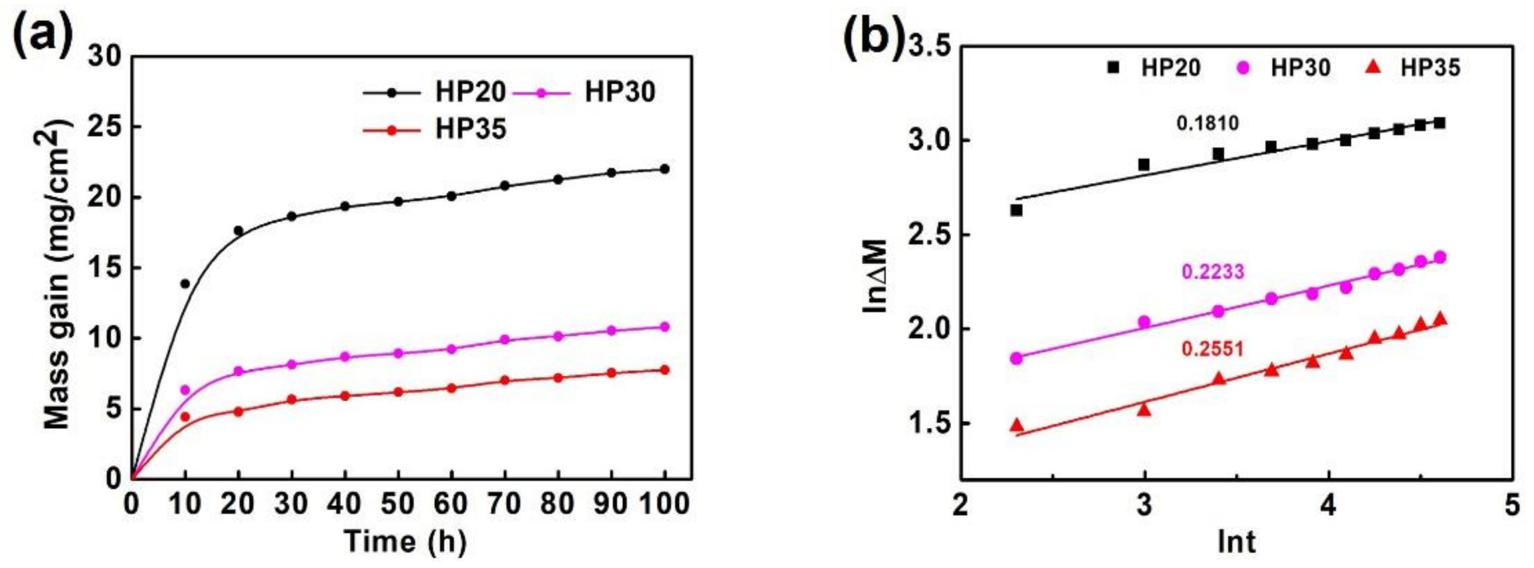
3.2. Oxidation Kinetics

The isothermal oxidation behavior of γ-TiAl-based alloys was evaluated by the mass gain per unit area. Figure 2 shows the oxidation kinetics curves of alloys with different porosities oxidized at 900 °C. It could be derived from Figure 2a that the mass gains of HP20, HP30, and HP35 after 100 h exposure were about 21.99, 10.79, and 7.75 mg/cm2, respectively. That is, alloys with larger porosities had larger mass gains. It was well understood because the presence of pores increased the reaction area. Apart from the alloy surface, oxidizing reaction also occurred at the interior gas-solid interface; thus larger porosities definitely led to more severe oxidation. The increased reaction area was the main reason, however, it was not the only one. Other reasons will be further discussed.
As seen in Figure 2a, during the first 20 h of exposure, the mass gains increased rapidly and then leveled off at a relatively slow rate in the following exposure. All mass change curves followed the typical parabolic law, revealing that the diffusion-controlled scale growth took place. In this case, the mass gain per unit area (ΔM in mg/cm2) as a function of time (t in h) at a given temperature obeys a law given by:
Δ M n = k n   ×   t
where n represents the power exponent, and kn (mgn·cm−2n·h−1) is the oxidation rate constant. Taking once the logarithm of Equation (1), we can acquire the following relationship:
ln Δ M = 1 n ln t + 1 n ln k n
Plotting lnΔM versus lnt yields the kn and n values. The plots of lnΔM and lnt fitted from the mass gain curves are displayed in Figure 2b, and the calculated values of kn and n are listed in Table 2. The calculated kn for HP20, HP30, and HP35 were 12.5524, 5.9785, and 3.3241 mgn·cm−2n·h−1, respectively. Generally, alloys with lower kn values exhibit slower oxidation kinetics and are thus more resistant to oxidation. This is in accordance with the mass gain results mentioned above. Furthermore, the n values decreased from 5.5249 to 3.9200 with the pressure raised from 20 to 35 MPa. Smaller values of n declared that the formed scale was denser, in which case, the metal cations and oxygen ions diffused with more difficulty, thereby hindering the growth of the oxide scale. For the three samples, since the chemical composition was the same and the microstructural differences were relatively small, the regularly varied n values should be affected by metallurgical defects.

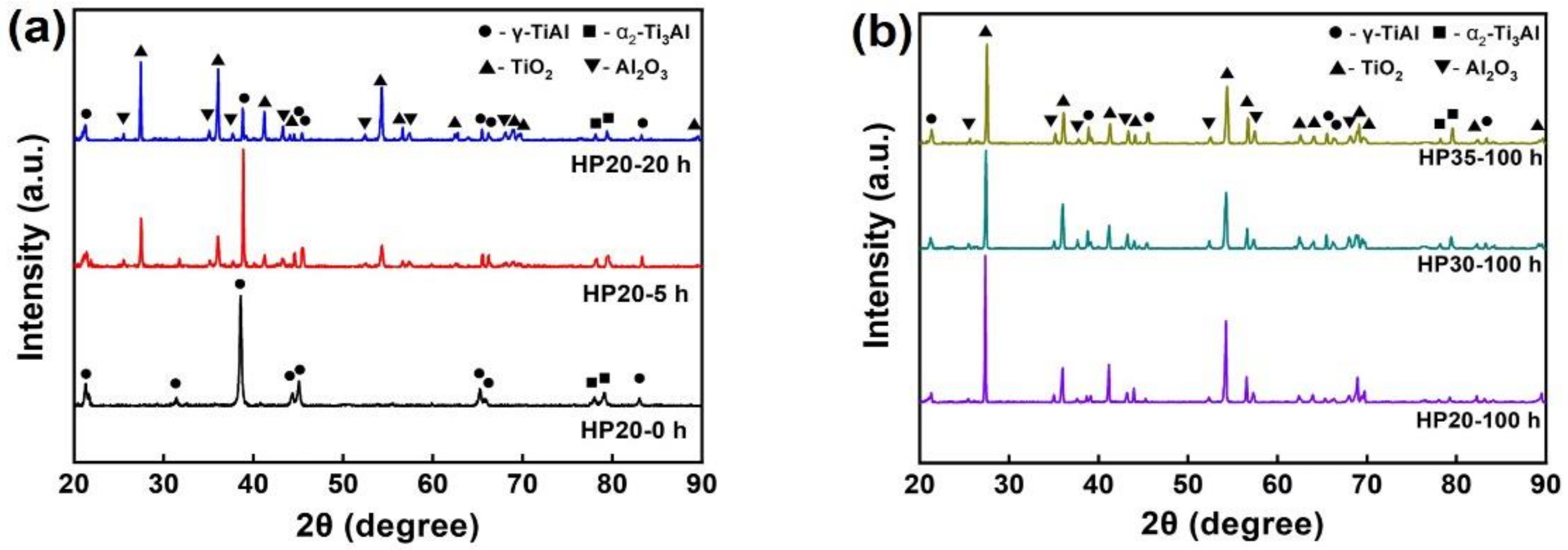
3.3. Phase Composition of Oxide Scale

Figure 3 exhibits the XRD spectra of the alloys after oxidation for different durations. For HP20 before oxidation treatment, as shown in Figure 3a, the diffraction peaks corresponded to the γ-TiAl and α2-Ti3Al, respectively. After being oxidized for 5 h, distinct new peaks for Al2O3 and TiO2 emerged. With extension of the oxidation time to 20 h, the peak intensities for the TiAl phases weakened and those assigned to oxide phases enhanced, revealing the growth of the oxide scale. When the oxidation time reached 100 h, as exhibited in Figure 3b, some diffraction peaks of TiAl phases were undetectable. The diffractogram also proved the presence of only Al2O3 and TiO2 phases, and no Nb- or Cr-based oxides were found. For HP30 and HP35, the diffraction peaks assigned to Al2O3 and TiO2 were also observed. However, the peak intensities for the three samples were different, indicating that the growth behaviors of the oxide scale were influenced by alloy porosities.

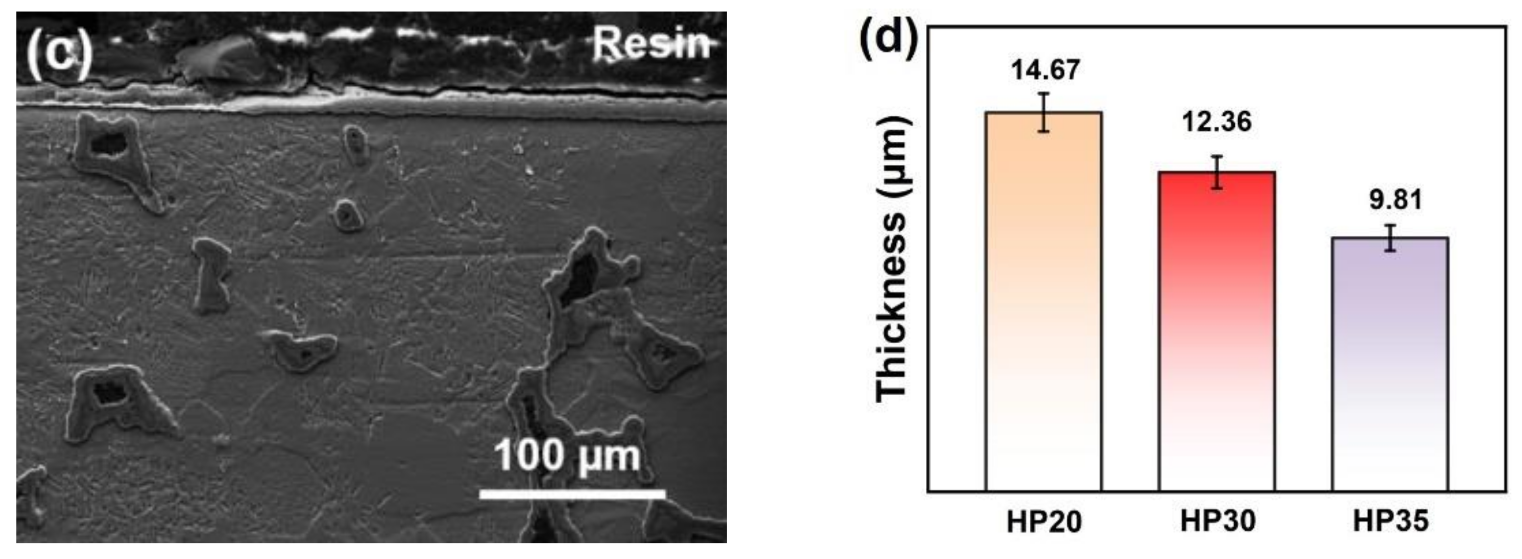
3.4. Morphology Feature of Oxide Scale

Figure 4 exhibits the SEM micrographs of the surface oxide scale for γ-TiAl-based alloys oxidized for 100 h. It could be found in Figure 4a–c that pores, despite their various shapes and sizes, disappeared entirely from the alloy surfaces after oxidation. No spallation or crack was observed on the oxide scale, but numerous micro-clusters emerged. In this case, we deduced that the clusters might grow from the positions of surface pores. High-magnification micrograph of the cluster displayed in the insert in Figure 4b revealed that numerous single-crystal oxide particles existed on the clusters. The chemical composition of the cluster marked in Figure 4b are listed in Table 3. As seen, the extremely low Al content indicated that the oxide particles on the clusters were ascribed to TiO2 particles.
Moreover, the number of these clusters decreased with the increase in alloy densities. For HP20, a certain number of clusters were even connected to each other. As to HP35, the surface clusters were distributed separately. The section sizes of the clusters were measured, and the average values for HP20, HP30, and HP35 were calculated and displayed in Figure 4d. With the increased sintering pressure, the average section size decreased from 51.91 μm to 35.68 μm accordingly. In addition, no distinct microstructural difference was observed in areas without oxide clusters for the three samples. Considering the decreased amount and sizes of pores (discussed in Section 3.1), these results further confirmed the above deduction that the clusters formed at the positions of surface pores.
Figure 5 displays the 3D LSM images and 2D profile lines of the oxide scale for alloys oxidized at 900 °C for 100 h. For HP20 shown in Figure 5a, the red and yellow humps were ascribed to the oxide clusters. Similar humps reduced with the increased pressures, and only a few were observed for HP35 exhibited in Figure 5c. Accordingly, as seen in Figure 5d, the 2D profile line for HP20 was extremely uneven and became relatively smooth when referring to HP35. The calculated Ra values for HP20, HP30, and HP35 were 8.88, 5.53, and 4.58 nm, respectively, revealing that the oxide scale for samples prepared using higher pressures was more rough. All these results confirmed the above analyses about the surface morphology. More importantly, it could be concluded that the vertical heights of the oxide clusters (not only their section sizes) also increased with the surface pore sizes.
Figure 6 shows the cross section and the average thickness of the oxide scale for the three alloys after oxidation for 100 h. The oxide layers in some interior pores could be clearly seen in Figure 6a–c, confirming that the oxidizing reaction occurred at the gas–solid interface inside the alloys as mentioned in Section 3.2. Moreover, the surface pores were filled with the oxidation products. These oxides grew to be the surface oxide clusters on most pores, while they could also turn to be the flat oxide scale in some cases. Further observation revealed that the pores below the large oxide clusters were usually large. However, it was different the other way around; the clusters grown on the large pores were not all large. For areas without any surface defects, the oxide scale possessed a regular morphology. The average thickness of the oxide scale for HP20, HP30, and HP35 shown in Figure 6d were 14.67, 12.36, and 9.81 μm, respectively. Apparently, the increased scale thickness was also caused by the increased amount and sizes of surface pores.
On the basis of the above morphological characterization, two other reasons for the larger mass gains for samples with larger porosities were determined. On the one hand, the oxide scale was thicker and consequently had larger mass. On the other hand, the emerged oxide clusters had larger amount and volume, thereby leading to the larger mass gains.

3.5. Chemical Composition of Oxide Scale

Although the morphologies were different, each thin layer of oxides which made up the entire oxide scale should be basically the same since the alloy composition was unchanged. Therefore, HP30 was selected as the representative sample to discuss the chemical composition of the oxide scale. Figure 7 displays the element distribution of Al, Ti, O, Cr, and Nb in the cross section of HP30 after oxidation for 100 h. In Figure 7a, an oxide scale piece fell from the top of the cluster during the sample preparation process. This was important evidence that revealed that the outer layer of the cluster was TiO2 because of the relatively low Ti content at the same area in Figure 7b. In addition, the TiO2 layer was also the outermost one at the flat part. Subsequently, a continuous intermediate layer consisting of Al2O3 was confirmed by Figure 7c. This layer was dense and could hinder the diffusion of oxygen into the interior. According to Figure 7b,c, a relatively thick layer made up of mixed Al2O3 and TiO2 particles was found under the Al2O3 layer for the flat area. At the center of the surface defect, these particle sizes were relatively larger.
In Figure 7e, it was found that Cr did not enrich during oxidation. According to Pilone’s work [38], a high Cr content could promote the formation of a continuous (Ti(Cr,Al)2) phase in the subsurface. When the Cr content was low, it existed in the form of low-valence Cr3+ and was dispersed in oxide scale. Normally, Cr3+ could increase the vacancy concentration of O and promote the formation of TiO2 [39]. Since the Cr content of the alloys prepared in this study was only 2%, the Cr element did not enrich or form other phases. On the contrary, the distribution of Nb element was somewhat complex. As shown in Figure 7f, Nb was distributed in the mixed oxide layer and the outermost TiO2 layer. It is well known that Nb is an element that improves the oxidation resistance of TiAl-based alloy effectively at high temperatures. It can occupy the gap of TiO2 and inhibit the inward diffusion of O during the high-temperature oxidation process [40,41]. That is, Nb existed in the oxide layers that contained (or consisted of) TiO2 particles.

3.6. Formation Mechanism of Oxide Clusters

The formation mechanism of oxide scale on the alloy surface was discussed, and the schematic diagram is shown in Figure 8. For the oxidation process of the alloy surface in the flat area as exhibited in Figure 8a, a mixture layer of TiO2 and Al2O3 formed at the early stage [17]. Al2O3 grew selectively and spread horizontally above the mixture layer [42], while Ti continued to spread to the outer layer to form TiO2. With the extension of oxidation time, Al2O3 became dense gradually, and TiO2 grew in the outermost layer continuously. An Nb-rich region was not detected in this work, probably because the sample was severely corroded. However, it has been reported by previous works that Nb enrichment between the matrix and the oxide layer was formed at the initial stage of oxidation [43,44].
Figure 8b shows the oxidation process of the alloy surface with defects. The emerged oxide clusters reveal that the oxide growth rate at the defects was higher than that of the flat area. According to the geometrical shape, a typical surface defect was divided into two regions, labeled Region 1 and 2. In Region 1, Ti and Al elements tended to diffuse to the tip, thereby leading to the fast oxidation rate. In this case, TiO2 and Al2O3 particles formed and grew uniformly. Meanwhile, Ti in the alloy diffused continuously to the outermost layer through the TiO2 channels [45] to form the TiO2 layer. Region 2 was equivalent to a convex cone, where Ti and Al diffused to the adjacent surface, and consequently the oxidation rate was slow. Therefore, oxide clusters formed at the positions of surface defects.

4. Conclusions

In this study, γ-TiAl-based alloy was successfully prepared by powder metallurgy. The oxidation behaviors of the alloys at 900 °C in air up to 100 h and the effects of surface defects on the morphology of the oxide scale were studied, and the following conclusions were drawn.
(1)
For alloys prepared at sintering pressures that increased from 20 to 35 MPa, the sintering necks tendered to grow; thus, the metallurgical defects decreased in amount and size unceasingly.
(2)
In the cyclic oxidation process, the existence of defects increased the actual contact area between the alloy and O. With the decrease of defects, the oxidation weight gain per unit area decreased continuously.
(3)
The oxide clusters normally formed at the positions of surface defects. When the number and size of the surface defects decreased, the number and sizes of the oxide clusters decreased accordingly.
(4)
Element diffusion to the inner face of the defects led to the formation of large TiO2 and Al2O3 particles, which should be the main reason for the formation of oxide clusters.

Author Contributions

Conceptualization, Z.S. and X.S.; methodology, Z.S.; validation, Y.H., Y.L., and X.S.; formal analysis, Z.S. and H.H.; investigation, Z.D.; resources, H.C.; data curation, Z.S.; writing—original draft preparation, Z.S.; writing—review and editing, Z.S. and Z.D.; supervision, H.C.; project administration, X.S. and Y.L.; funding acquisition, X.S., Y.L. and Y.H. All authors have read and agreed to the published version of the manuscript.

Funding

This work was supported by the Fund of Education department of JiLin Province (No.JJKH20210733KJ), the Jilin Scientific and Technological Development Program (YDZJ202201ZYTS669), the Natural Science Foundation of China (52105334) and the Natural Science Foundation of Hunan Province of China (2021JJ40206, 2022JJ20025).

Data Availability Statement

The data presented in this study are available on request from the corresponding author.

Conflicts of Interest

The authors declare no conflict of interest.

References

  1. Pradeep, N.B.; Hegde, M.M.R.; Rajendrachari, S.; Surendranathan, A.O. Investigation of Microstructure and Mechanical Properties of Microwave Consolidated Timgsr Alloy Prepared by High Energy Ball Milling. Powder Technol. 2022, 408, 117715. [Google Scholar] [CrossRef]
  2. Basavarajappa, P.N.; Hegde, M.M.R.; Rajendrachari, S.; Surendranathan, A.O. Investigation of Structural and Mechanical Properties of Nanostructured Timgsr Alloy for Biomedical Applications. Biointerface Res. Appl. Chem. 2022, 13, 118. [Google Scholar] [CrossRef]
  3. Liu, Y.; Wu, Z.; Wang, Q.; Zhao, L.; Zhang, X.; Gao, W.; Xu, J.; Song, Y.; Song, X.; Zhang, X.J.C. Optimization of Parameters in Laser Powder Bed Fusion TA15 Titanium Alloy Using Taguchi Method. Crystals 2022, 12, 1385. [Google Scholar] [CrossRef]
  4. Liu, Y.; Wu, Z.; Liu, W.; Ma, Y.; Zhang, X.; Zhao, L.; Yang, K.; Chen, Y.; Cai, Q.; Liang, C.; et al. Microstructure Evolution and Reaction Mechanism of Continuously Compositionally Ti/Al Intermetallic Graded Material Fabricated by Laser Powder Deposition. J. Mater. Res. Technol. 2022, 20, 4173–4185. [Google Scholar] [CrossRef]
  5. Liu, C.; Liu, Y.; Wang, T.; Liu, W.; Ma, Y.J.M.S.; Treatment, H. Effects of Heat Treatment on the Microstructure and Properties of Graded-Density Powder Aluminum Alloys. Met. Sci. Heat Treat. 2022, 63, 590–598. [Google Scholar] [CrossRef]
  6. Kothari, K.; Radhakrishnan, R.; Wereley, N.M. Progress in Aerospace Sciences Advances in Gamma Titanium Aluminides and Their Manufacturing Techniques. Prog. Aerosp. Sci. 2012, 55, 1–16. [Google Scholar] [CrossRef]
  7. Appel, F.; Wagner, R. Microstructure and Deformation of Two-Phase γ-Titanium Aluminides. Mater. Sci. Eng. R Rep. 1998, 22, 187–268. [Google Scholar] [CrossRef]
  8. Zhang, S.; Tian, S.; Lv, X.; Yu, H.; Tian, N.; Jiao, Z.; Zhao, G.; Li, D. Deformation and Damage Behaviors of As-Cast TiAl-Nb Alloy during Creep. Prog. Nat. Sci. Mater. Int. 2018, 28, 618–625. [Google Scholar] [CrossRef]
  9. Duan, Z.; Han, Y.; Song, X.; Chen, H. Creep Behaviour of Equiaxed Fine-Grain γ-TiAl-Based Alloy Prepared by Powder Metallurgy. Mater. Sci. Technol. U. K. 2020, 36, 1457–1464. [Google Scholar] [CrossRef]
  10. Xuezheng, W.; Zhenxin, D.; Hua, C. High Temperature Mechanical Properties and Deformation Mechanism of Equiaxed Fine-Grained Ti-45 7 Nb Alloys. Rare Met. Mater. Eng. 2022, 51, 1543–1549. [Google Scholar]
  11. Dobbelstein, H.; Gurevich, E.L.; George, E.P.; Ostendorf, A.; Laplanche, G. Laser Metal Deposition of a Refractory TiZrNbHfTa High-Entropy Alloy. Addit. Manuf. 2018, 24, 386–390. [Google Scholar] [CrossRef]
  12. Wen, Z.; Song, X.; Chen, D.; Fan, T.; Liu, Y.; Cai, Q. Electrospinning Preparation and Microstructure Characterization of Homogeneous Diphasic Mullite Ceramic Nanofibers. Ceram. Int. 2020, 46, 12172–12179. [Google Scholar] [CrossRef]
  13. Song, X.; Zhang, K.; Song, Y.; Duan, Z.; Liu, Q.; Liu, Y. Morphology, Microstructure and Mechanical Properties of Electrospun Alumina Nanofibers Prepared Using Different Polymer Templates: A Comparative Study. J. Alloys Compd. 2020, 829, 154502. [Google Scholar] [CrossRef]
  14. Hu, M.; Wang, L.; Li, G.; Huang, Q.; Liu, Y.; He, J.; Wu, H.; Song, M.J.I. Investigations on Microstructure and Properties of Ti-Nb-Zr Medium-Entropy Alloys for Metallic Biomaterials. Intermetallics 2022, 145, 107568. [Google Scholar] [CrossRef]
  15. Zhao, Q.; Pan, Z.; Wang, X.; Luo, H.; Liu, Y.; Li, X. Corrosion and Passive Behavior of Alxcrfeni3-x (x = 0.6, 0.8, 1.0) Eutectic High Entropy Alloys in Chloride Environment. Corros. Sci. 2022, 208, 110666. [Google Scholar] [CrossRef]
  16. Pflumm, R.; Friedle, S.; Schütze, M. Oxidation Protection of γ-TiAl-Based Alloys—A Review. Intermetallics 2015, 56, 1–14. [Google Scholar] [CrossRef]
  17. Dai, J.; Zhu, J.; Chen, C.; Weng, F. High Temperature Oxidation Behavior and Research Status of Modifications on Improving High Temperature Oxidation Resistance of Titanium Alloys and Titanium Aluminides: A Review. J. Alloys Compd. 2016, 685, 784–798. [Google Scholar] [CrossRef]
  18. Pflumm, R.; Donchev, A.; Mayer, S.; Clemens, H.; Schütze, M. High-Temperature Oxidation Behavior of Multi-Phase Mo-Containing γ-TiAl-Based Alloys. Intermetallics 2014, 53, 45–55. [Google Scholar] [CrossRef]
  19. Appel, F.; Paul, J.D.H.; Oehring, M. Gamma Titanium Aluminide Alloys Science and Technology; John Wiley & Sons: Hoboken, NJ, USA, 2011; ISBN 9783527322619. [Google Scholar]
  20. Jie, L. Isothermal Oxidation Behavior of TiAl-Nb-W-B-Y Alloys with Different Lamellar Colony Sizes. Rare Met. Mater. Eng. 2016, 45, 1695–1699. [Google Scholar] [CrossRef]
  21. Rakowski, J.M.; Meier, G.H.; Pettit, F.S.; Dettenwanger, F.; Schumann, E.; Rühle, M. The Effect of Surface Preparation on the Oxidation Behavior of Gamma TiA1-Base Intermetallic Alloys. Scr. Mater. 1996, 35, 1417–1422. [Google Scholar] [CrossRef]
  22. Copland, E.H.; Gleeson, B.; Young, D.J. Formation of Z-Ti50Al30O20 in the Sub-Oxide Zones of γ-TiAl-Based Alloys during Oxidation at 1000 °C. Acta Mater. 1999, 47, 2937–2949. [Google Scholar] [CrossRef]
  23. Paul, J.D.H.; Lorenz, U.; Oehring, M.; Appel, F. Up-Scaling the Size of TiAl Components Made via Ingot Metallurgy. Intermetallics 2013, 32, 318–328. [Google Scholar] [CrossRef] [Green Version]
  24. Zhao, J.; Zhang, Z.; Liu, S.; Shi, K.; Bao, C.; Ning, Z.; Yan, P.; Wang, L.; Lou, Y. Elimination of Misrun and Gas Hole Defects of Investment Casting TiAl Alloy Turbocharger Based on Numerical Simulation and Experimental Study. China Foundry 2020, 17, 29–34. [Google Scholar] [CrossRef] [Green Version]
  25. Bao, C.; Zhang, S.; Ren, Y.; Zhang, Y.; Xie, H.; Zhao, J. Research Progress on Refractory Composition and Deformability of Shell Molds for TiAl Alloy Castings. China Foundry 2018, 15, 1–10. [Google Scholar] [CrossRef] [Green Version]
  26. Xia, Y.; Yu, P.; Schaffer, G.B.; Qian, M. Cobalt-Doped Ti-48Al-2Cr-2Nb Alloy Fabricated by Cold Compaction and Pressureless Sintering. Mater. Sci. Eng. A 2013, 574, 176–185. [Google Scholar] [CrossRef]
  27. Kayani, S.H.; Park, N.K. Effect of Cr and Nb on the Phase Transformation and Pore Formation of Ti-Al Base Alloys. J. Alloys Compd. 2017, 708, 308–315. [Google Scholar] [CrossRef]
  28. Correa, D.R.N.; Grandini, C.R.; Rocha, L.A.; Proenca, J.P.; Sottovia, L.; Cruz, N.C.; Rangel, E.C.; Hanawa, T. Effect of temperature on thermal oxidation behavior of biomedical ti-zr-mo alloys. J. Alloys Compd. 2022, 905, 164202. [Google Scholar] [CrossRef]
  29. Yue, H.; Peng, H.; Li, R.; Su, Y.; Zhao, Y.; Qi, K.; Chen, Y. Selective Electron Beam Melting of TiAl Alloy: Metallurgical Defects, Tensile Property, and Determination of Process Window. Adv. Eng. Mater. 2020, 22, 1–9. [Google Scholar] [CrossRef]
  30. Li, J.; Feng, R.; Qiao, H.; Li, H.; Wang, M.; Qi, Y.; Lei, C. Effect of Cutting Crystal Directions on Micro-Defect Evolution of Single Crystal γ-TiAl Alloy with Molecular Dynamics Simulation. Metals 2019, 9, 1278. [Google Scholar] [CrossRef] [Green Version]
  31. Xu, Z.; Ouyang, W.; Liu, Y.; Jiao, J.; Liu, Y.; Zhang, W. Effects of Laser Polishing on Surface Morphology and Mechanical Properties of Additive Manufactured TiAl Components. J. Manuf. Process. 2021, 65, 51–59. [Google Scholar] [CrossRef]
  32. Cai, X.; Sun, D.; Li, H.; Meng, C.; Wang, L.; Shen, C. Dissimilar Joining of TiAl Alloy and Ni-Based Superalloy by Laser Welding Technology Using V/Cu Composite Interlayer. Opt. Laser Technol. 2019, 111, 205–213. [Google Scholar] [CrossRef]
  33. Wu, H.N.; Xu, D.S.; Wang, H.; Yang, R. Molecular Dynamics Simulation of Tensile Deformation and Fracture of γ-TiAl with and without Surface Defects. J. Mater. Sci. Technol. 2016, 32, 1033–1042. [Google Scholar] [CrossRef]
  34. Huang, Z.W.; Lin, J.P.; Zhao, Z.X.; Sun, H.L. Fatigue Response of a Grain Refined TiAl Alloy Ti-44Al-5Nb-1W-1B with Varied Surface Quality and Thermal Exposure History. Intermetallics 2017, 85, 1–14. [Google Scholar] [CrossRef]
  35. Patriarca, L.; Milano, P.; Pasquero, G.; Avio, S.A.; Sabbadini, S. Gt2012-69986 Assessment of Fatigue Sensitivity to Defects of a TiAl Alloy. In Turbo Expo: Power for Land, Sea, and Air; American Society of Mechanical Engineers: New York, NY, USA, 2012; pp. 1–6. [Google Scholar]
  36. Trzaska, Z.; Couret, A.; Monchoux, J.P. Spark Plasma Sintering Mechanisms at the Necks between TiAl Powder Particles. Acta Mater. 2016, 118, 100–108. [Google Scholar] [CrossRef]
  37. Duan, Z.; Song, X.; Han, Y.; Pei, W.; Chen, H. Enhancing High-Temperature Strength and Ductility of γ-TiAl Matrix Composites with Controllable Dual Alloy Structure. Mater. Sci. Eng. A 2021, 823, 141723. [Google Scholar] [CrossRef]
  38. Pilone, D.; Felli, F.; Brotzu, A. High Temperature Oxidation Behaviour of TiAl-Cr-Nb-Mo Alloys. Intermetallics 2013, 43, 131–137. [Google Scholar] [CrossRef]
  39. Lee, D.B. Effect of Cr, Nb, Mn, V, W and Si on High Temperature Oxidation of TiAl Alloys. Met. Mater. Int. 2005, 11, 141–147. [Google Scholar] [CrossRef]
  40. Qu, S.J.; Tang, S.Q.; Feng, A.H.; Feng, C.; Shen, J.; Chen, D.L. Microstructural Evolution and High-Temperature Oxidation Mechanisms of a Titanium Aluminide Based Alloy. Acta Mater. 2018, 148, 300–310. [Google Scholar] [CrossRef]
  41. Terner, M.; Biamino, S.; Baudana, G.; Penna, A.; Fino, P.; Pavese, M.; Ugues, D.; Badini, C. Initial Oxidation Behavior in Air of TiAl-2Nb and TiAl-8Nb Alloys Produced by Electron Beam Melting. J. Mater. Eng. Perform. 2015, 24, 3982–3988. [Google Scholar] [CrossRef]
  42. Zhao, L.; Zhang, Y.; Zhu, Y.; Lin, J.; Ren, Z. Oxidation Behavior of γ-TiAl Based Alloys at 900 °C in Air. Mater. High Temp. 2016, 33, 234–240. [Google Scholar] [CrossRef]
  43. Małecka, J. Resistance to High-Temperature Oxidation of Ti-Al-Nb Alloys. Materials 2022, 15, 2137. [Google Scholar] [CrossRef] [PubMed]
  44. Naveed, M.; Renteria, A.F.; Weiß, S. Role of Alloying Elements during Thermocyclic Oxidation of β/γ-TiAl Alloys at High Temperatures. J. Alloys Compd. 2017, 691, 489–497. [Google Scholar] [CrossRef]
  45. Kim, D.; Seo, D.; Huang, X.; Sawatzky, T.; Saari, H.; Hong, J.; Kim, Y.W. Oxidation Behaviour of Gamma Titanium Aluminides with or without Protective Coatings. Int. Mater. Rev. 2014, 59, 297–325. [Google Scholar] [CrossRef]
Figure 1. SEM micrographs of PM γ-TiAl-based alloys: (a) HP20; (b) HP30; (c) HP35; and (d) HP35 at high magnification.
Metals 12 01743 g001
Figure 2. Isothermal oxidation kinetics of γ-TiAl-based alloys oxidized at 900 °C: (a) mass gain vs. time curves; (b) plots of lnΔM and lnt fitted from the curves in (a).
Metals 12 01743 g002
Figure 3. XRD spectra of γ-TiAl-based alloys after oxidation: (a) HP20 oxidized for 0, 5 and 20 h; (b) HP20, HP30, and HP35 oxidized for 100 h.
Metals 12 01743 g003
Figure 4. SEM micrographs of the oxide scale for γ-TiAl-based alloys oxidized at 900 °C for 100 h: (a) HP20; (b) HP30; (c) HP35; and (d) average sizes of the surface oxide clusters.
Metals 12 01743 g004
Figure 5. 3D LSM images of the oxide scale for γ-TiAl-based alloys oxidized at 900 °C for 100 h: (a) HP20; (b) HP30; (c) HP35; and (d) the corresponding 2D profile lines.
Metals 12 01743 g005
Figure 6. The cross section of γ-TiAl-based alloys after oxidation for 100 h: (a) HP20; (b) HP30; (c) HP35; and (d) the mean thickness of the oxide scale (the thickness values were acquired by measuring the regular area of the oxide scale).
Metals 12 01743 g006aMetals 12 01743 g006b
Figure 7. The EDS element mapping of the cross section for HP30 after oxidation for 100 h: (a) SEM micrograph; (bf) elements of Al, Ti, O, Cr, and Nb, respectively.
Metals 12 01743 g007
Figure 8. Schematic diagram of formation mechanism of oxide scale on alloy surface: (a) flat area; (b) with defects. Region 1 and 2 shows the bottom and the top of a typical surface defect, respectively.
Metals 12 01743 g008
Table 1. The sintered densities and porosities of the prepared PM γ-TiAl-based alloys.
SamplesSintered Density (g/cm3)Porosity (%)
HP203.48411.8
HP303.6008.9
HP353.7724.6
Table 2. Calculated n and k values of the γ-TiAl-based alloys.
Samplesnkn (mgn·cm−2n·h−1)
HP205.524912.5524
HP304.47825.9785
HP353.92003.3241
Table 3. Chemical composition of the oxide clusters examined by EDS.
Composition (at%)Deduced Phase
TiAlO
29.451.0669.49TiO2
Publisher’s Note: MDPI stays neutral with regard to jurisdictional claims in published maps and institutional affiliations.

