Abstract
This article provides an overview of high-pressure die casting (HPDC)-related research undertaken at the EPSRC Future LiME Hub between 2015–2022. The project aimed to identify the cause of variability in the tensile ductility of die-cast structures, and to develop novel processing techniques to address this issue. Variability in tensile ductility was related to the size of large pores and non-metallic inclusions. It was proposed that these non-metallic inclusions formed during the pyrolysis of commercial plunger lubricants in the shot sleeve, and that these large pores derived from dilatational strains introduced during semi-solid deformation. Processing parameters and die design were found to significantly influence the microstructure of die-cast products, and the subsequent variability in tensile ductility. To close, recent progress on the application of intensive melt shearing to HPDC is reviewed. Intensive melt shearing was found to induce significant grain refinement in both Al and Mg alloys due to the effective dispersion of native oxide particles, and the use of these particles as heterogeneous nucleation substrates. The presence of native oxide particles also enabled the use of novel heat treatment procedures that avoided conventional issues such as surface blistering and geometrical distortion.
1. Introduction
High-pressure die casting (HPDC) is often used to manufacture lightweight structures for automobiles and aeroplanes due to its high productivity and cast dimensional accuracy. The process is characterised by the high-speed injection of molten metal into a sealed mould cavity, followed by solidification under hydrostatic pressures of 30–100 MPa [1]. It thus elicits complex phenomena including fluid turbulence, solidification, and semi-solid deformation. These phenomena make HPDC inherently probabilistic, with the tensile ductility of die castings known to be highly variable [2,3,4]. This variability leads to high scrap rates (5–10%) and increased safety factors for component design. Though the tensile ductility of die castings has been linked to several casting defects (e.g., porosity [5,6,7], oxides [8,9], and intermetallic phases [9,10,11]), the underlying cause of variability is presently unknown.
Previous investigations into the variable properties of die castings can be broadly divided into three categories: (i) those that relate the variability in tensile ductility to statistical variations in melt quality [8,9,10,12]; (ii) those that derive empirical correlations between the tensile ductility and various measures of microstructural heterogeneity [5,6,7,13,14,15]; and (iii) those that consider the stochastic nature of fluid flow and the subsequent encapsulation of air and oxides [16,17,18,19]. While porosity is a recurrent theme in these studies, its formation mechanism is widely disputed. For example, Tian et al. [9] relate the amount of porosity to the number of inclusions in the melt; Li et al. [13] observe a linear correlation between the volume fraction of porosity and the amount of primary α-Al1 crystals nucleated in the shot sleeve; Dong et al. [2] report that the use of vacuum can lead to fewer pores and reduced scatter in tensile ductility. Several high-integrity processes [20] have, therefore, been developed to reduce the amount of porosity in die-cast structures, but have met with limited success. It is clear that further understanding is required to facilitate a major advance in processing technologies.
The Future Liquid Metal Engineering Hub (Future LiME Hub) is a research programme supported by the Engineering and Physical Sciences Research Council (EPSRC) and industrial companies. The overarching focus of the EPSRC Future LiME Hub is to realise a vision of full metal circulation, where the global demand for metallic materials is met by a circulation of secondary metals (with limited additions of primary metals each year). A subdivision of the EPSRC Future LiME Hub was tasked with developing sustainable metal processing technologies for the UK manufacturing industry and its supply chain. Here, we present an overview of HPDC-related research carried out by this subdivision between 2015–2022. The project aimed to: (i) establish a numerical model of the HPDC process; (ii) identify the primary cause of variability in tensile ductility; (iii) investigate the effect of processing parameters and die design on microstructural evolution and defect formation; and to (iv) develop novel high-integrity processing techniques for HPDC. Section 2 describes the numerical model used to simulate fluid flow, heat transfer, and solidification in the HPDC process. Section 3 deals with objectives (ii) and (iii), revealing the primary sources of variability in tensile ductility and exploring ways to reduce defect size using existing HPDC equipment. Finally, recent progress on the application of intensive melt shearing to HPDC is reviewed in Section 4.
2. Numerical Modelling of the HPDC Process
Numerical modelling is a powerful and cost-effective tool that is commonly used in the design of cast systems and the selection of processing parameters. With advanced parallel computing techniques, and a variety of mathematical models, physical phenomena including fluid flow, heat transfer, solidification, and defect formation can be modelled in a timely and detailed manner. Dou et al. [19,21,22] modelled the HPDC process using the finite element method (FEM) under the ProCAST (ESI Group) software platform. An overview of the modelling procedure is presented in the following paragraphs, with detailed accounts provided in references [19,21,22].
2.1. Overview of Modelling Procedure
The ProCAST software suite consists of three interactive modules for FEM mesh generation (Visual-MESH), model discretisation/calculation (Visual-CAST), and the visualisation/analysis of results (Visual-VIEWER). The HPDC machine was described geometrically using CAD software according to engineering drawings provided by the manufacturer (FRECH GmbH). For computational efficiency, symmetry was assumed along a plane parallel to the longitudinal axis of the shot sleeve (Figure 1). A hybrid FEM mesh was generated in the Visual-MESH module, with mesh size varying according to the local geometry and desired calculation precision. The model was then calculated in the Visual-CAST module using the parallel computing technique. The Visual-VIEWER module was then called for postprocessing and visualisation of the acquired data.
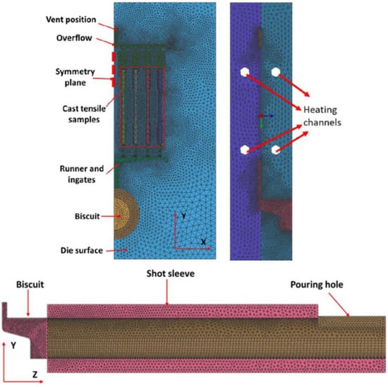
Figure 1.
Geometry and hybrid FEM mesh (1/2 symmetry) used in ProCAST simulations of the HPDC process. A symmetry plane is constructed parallel to the Y-Z plane, with half the model used in the calculations. Reprinted with permission from ref. [21]. Copyright 2022 Elsevier.
2.2. Governing Equations
Fluid flow, heat transfer, and solidification were modelled in three-dimensional space using the following governing equations based on the enthalpy method:
Continuity equation:
Momentum equation:
Energy equations:
In the above equations, is density, the intrinsic phase averaged velocity, pressure, the gravity vector, the effective melt viscosity, temperature, specific heat capacity at constant pressure, latent heat of solidification, and enthalpy. The volume of fluid (VOF) method was used to model the evolution of the melt free surface with time. Fluid turbulence was modelled using a standard - turbulence model described in references [23,24]. Further information regarding the governing equations and standard models used can be found in references [19,21,22].
2.3. Encapsulation of Air and Oxides
Air entrainment was predicted qualitatively using the GAS model [25], which combines the ideal gas law and the Darcy–Weisbach equation:
where is the pressure drop per unit length, the coefficient of friction due to surface roughness, the hydraulic diameter, and density is related to temperature and pressure through the ideal gas law. The effect of intensification pressure on solidification was accounted for using a critical gate solid fraction, which stopped liquid feeding once the local solid fraction reached 0.9.
The encapsulation of oxides was modelled using a front tracking indicator developed by ProCAST (ESI Group), which has units cm2s. The action of the front tracking indicator is as follows. At each point on the melt free surface, the surface area is multiplied by time. This value is cumulated to that of the previous time step and is transported with the fluid flow. When two free surfaces meet, the two values are added. When there is no free surface at a given location, the value is transported with the fluid flow. This front tracking indicator allows one to qualitatively assess the amount of oxides formed at the free surface and the likely position of these oxides in the final casting.
2.4. Near-Wall Flow and Heat Transfer
Fluid flow experiences a boundary layer for velocity magnitude in the near-wall region between the melt and mould surface. Moreover, time-dependent interfacial heat transfer coefficients arise when the liquid contacts the mould. Two internal functions, WSHEAR and WALLF, were used to describe fluid flow near to the mould wall. The WSHEAR function allows for non-zero velocities at the mould wall, whereas the WALLF function computes the velocity of the free surface at the mould wall. Time-dependent interfacial heat transfer coefficients were defined according to experiments performed by the authors [21,22]. Further information regarding the treatment of near-wall flow and heat transfer can be found in references [19,21,22].
3. Processing Parameters and Die Design
3.1. Effect of Plunger Speed Profile on Microstructure, Defects, and Mechanical Properties
Dou et al. [21] used the numerical model described in Section 2 to investigate the role of plunger kinematics on solidification and defect formation in HPDC, finding that an optimum slow shot plunger speed profile (0.4–0.6 ms−1) exists corresponding to limited air entrainment, reduced heat loss in the shot sleeve, and a homogeneous distribution of oxides in the as-cast material. Lordan et al. [26] subsequently performed HPDC experiments under Baseline (0.2–0.3 ms−1) and Optimised conditions to validate the model, and to investigate the underlying cause of variability in tensile ductility. Figure 2a,b show the tensile properties of samples produced under Baseline and Optimised conditions. The average values and standard deviations were unaffected by the change in plunger kinematics; however, the variability in tensile ductility was greatly reduced under Optimised conditions (i.e., if variability is defined as significant negative deviations from the arithmetic mean). For example, average values of 11.6 1.5% (min. 6.8%) and 11.9 1.4% (min. 9.4%) were reported for the tensile ductility of samples produced under Baseline and Optimised conditions, respectively. The reduced variability in tensile ductility, according to this definition, is evidenced by the increase in the minimum tensile ductility from 6.8% to 9.4% following the change in plunger kinematics from Baseline to Optimised. Variability in tensile ductility was related to the size of large pores and non-metallic inclusions, with representative backscattered electron micrographs of these defects shown in Figure 2c,d, respectively. The authors proposed that these non-metallic inclusions formed during the pyrolysis of commercial plunger lubricants in the shot sleeve, and that these large pores derived from dilatational strains introduced during semi-solid deformation.
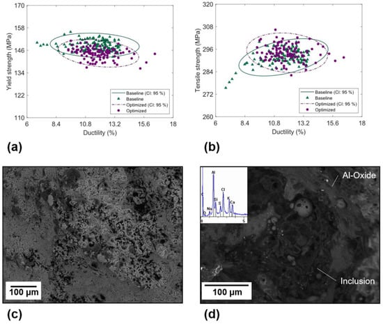
Figure 2.
Tensile properties of samples produced using the (a) Baseline, and (b) Optimised plunger speed profiles; 95% confidence ellipses are shown for two-dimensional, normally distributed data. Shown in (c,d) are representative backscattered electron micrographs of pores and inclusions observed on the fracture surface of tensile specimens, respectively [26].
During the intensification stage of the HPDC process, large hydrostatic pressures act on a semi-solid alloy, which consists of a heterogeneous network of solid grains saturated by a Newtonian fluid of dynamic viscosity. Metallic alloys with 60–95% solid deform as near-cohesionless granular materials, with solid grains rearranging to accommodate the applied stress [27,28,29]. Under compression, a pore may either contract or dilate depending on the solid fraction at which deformation takes place. At low solid fractions, grains can move towards one another, applying an external pressure on the pore driving contraction [30,31]. At high solid fractions, grains are densely packed, with grain rearrangement leading to shear-induced dilation and pore growth [30,31]. The maximum dilatational strain has been shown to increase with the solid fraction at which deformation takes place [30,31]. Figure 3a shows that the melt temperature at the end of die filling was 30 °C higher in the Optimised condition compared to the Baseline condition. The change in plunger kinematics from Baseline to Optimised would, therefore, lead to a decrease in the maximum volumetric strain encountered during semi-solid deformation. Dilatational strains are highly localised and time variant and may lead to the formation of a new pore or the sudden expansion of an existing pore. This dependency on the local grain structure may explain the seemingly random nature of pore formation in HPDC. Indeed, a more uniform grain structure was produced under Optimised conditions (Figure 3b,c), which would result in a more homogeneous strain field and reduced scatter in pore size.
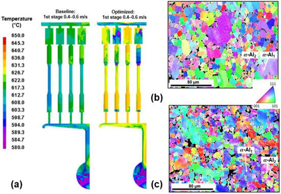
Figure 3.
(a) ProCAST simulations depicting melt temperature at the end of die filling for Baseline and Optimised conditions [21]. Shown in (b,c) are EBSD IPF maps taken from the centre of the gauge length of tensile specimens produced under Baseline and Optimised conditions, respectively, showing primary -Al grains nucleated in the shot sleeve (-Al1) and die cavity (-Al2) [26].
3.2. Turbulent Breakup of Non-Metallic Inclusions and Equiaxed Crystals
Members of the EPSRC Future LiME Hub have investigated the effect of die design on microstructural development and defect formation in the HPDC process. By altering the design of the runner system, Lordan et al. [32] were able to produce die-cast specimens under different flow field intensities. Figure 4a shows the rate of turbulent energy dissipation along the flow path of the studied dies. Higher rates of turbulent energy dissipation were observed in the lean runner system (LRS) compared to the conventional runner system (CRS). In addition, the melt experienced this high energy flow for a prolonged period in the LRS due to the increased pipe length. X-ray tomography was used to characterise inclusions in die-cast samples produced using the two dies. Figure 4b,c show plots of compactness vs. size for inclusions identified in the CRS and LRS samples, respectively; the insets of Figure 4b,c show three-dimensional visualisations of inclusions in each sample. Inclusions in the LRS sample were on average smaller in size, and more compact in morphology, than those in the CRS sample. For example, the average diameter of inclusions in the LRS and CRS samples were 0.09 0.03 mm (max. 0.37 mm) and 0.15 0.08 mm (max. 0.73 mm), respectively. Inclusions were also distributed more uniformly in the LRS sample than in the CRS, as shown by the insets in Figure 4b,c. A multivariate Gaussian mixture model (GMM) was used to identify species of inclusions contained within each X-ray tomography dataset. Each dataset was found to comprise a mixture of non-metallic inclusions, primary -Al15(FeMn)3Si2 phase, and -AlFeSi phase. These non-metallic inclusions varied significantly in size (80–1000 µm) and morphology (compact to highly irregular) and were proposed to form during the pyrolysis of commercial plunger lubricants in the shot sleeve [26]. The authors concluded that, in a turbulent flow, large non-metallic inclusions are broken down into more, smaller particles with a compact morphology. Increasing the rate of turbulent energy dissipation was shown to promote breakage, leading to an increase in tensile strength (+16% [32]) and tensile ductility (+68% [32]). Breakage is illustrated by the probability density (PDF) contours in Figure 4b,c, which show that the peaks of the GMM PDF move towards a region of higher compactness and lower diameter following an increase in the rate of turbulent energy dissipation.
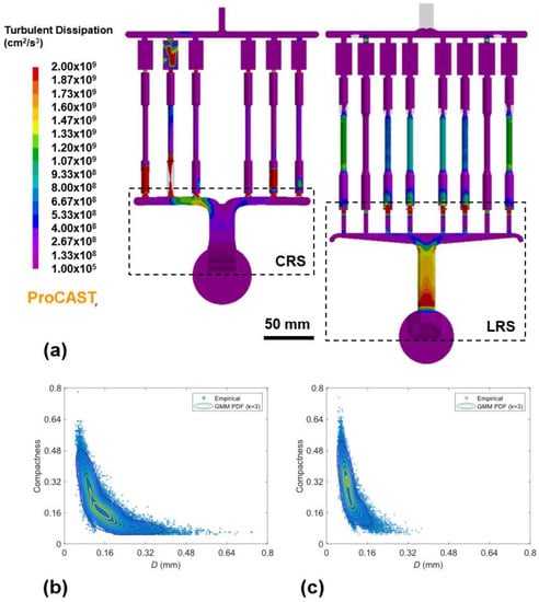
Figure 4.
(a) ProCAST simulations depicting the dissipation rate of turbulent kinetic energy along the flow path of the CRS and LRS dies. Shown in (b,c) are plots of compactness vs. size for inclusion identified in samples produced using the CRS and LRS dies, respectively. A Gaussian mixture model (GMM) was used to model each dataset, with probability density (PDF) contours superimposed on the plots in (b,c). The insets (i,ii) show a three-dimensional visualisation of inclusions in each sample [32].
An increased rate of turbulent energy dissipation was also accompanied by a refinement of large primary α-Al1 grains nucleated in the shot sleeve [32]. Shown in Figure 5 are grain size distributions for the CRS and LRS samples acquired by electron backscatter diffraction (EBSD) mapping. The grain size distributions are multimodal, an observation that is more pronounced in the CRS distribution than in the LRS distribution. Grain size distributions in die-cast materials are often assumed to be bimodal, i.e., they are thought to comprise of primary α-Al1 grains nucleated in the shot sleeve and primary α-Al2 grains nucleated in the die cavity. Primary α-Al1 grains (30–300 µm [33]) are much larger than primary α-Al2 grains (10 µm [33]) because the cooling rates in the shot sleeve (10 Ks−1 [14]) are much lower than those in the die cavity (5001000 Ks−1 [14]). Conversely, it is widely accepted that agitation of the liquid during solidification leads to grain refinement and morphological change [34,35,36,37,38]. To investigate this discrepancy, univariate GMMs were fitted to the grain size distributions in Figure 5. Akaike and Bayesian information criterions revealed that both grain size distributions were in fact trimodal: they comprised a mixture of primary α-Al1 grains nucleated in the shot sleeve, primary α-Al2 grains nucleated in the die cavity, and the fragmented dendrite arms of primary α-Al1 grains. Increasing the dissipation rate of turbulent kinetic energy led to a refinement of primary α-Al1 grains and an increased number density of fragmented dendrite arms. Synchrotron X-ray radiography experiments [39] have shown that a flow of interdendritic liquid can destabilise the local temperature–curvature–concentration equilibrium leading to local remelting of the dendrite root. In line with this, turbulent oscillations of the surrounding liquid may cause the local temperature and concentration to fluctuate intermittently, which may expedite the remelting process (the timescale of turbulence is likely to be smaller than the time required for thermal and constitutional equilibration). These findings present unique opportunities for scientific and technological development, particularly in the sphere of die design.
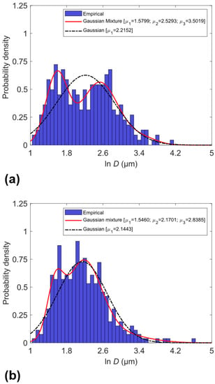
Figure 5.
Maximum Feret diameter of primary -Al grains in die-cast samples produced using the CRS (a) and LRS (b). The solid curve represents the probability density predicted from a multivariate Gaussian mixture model (GMM); the dash-dotted curve represents a simple Gaussian distribution [32].
4. Application of Intensive Melt Shearing to HPDC
4.1. High Shear Melt Conditioning (HSMC)
The high shear melt conditioning (HSMC) process, developed and patented by BCAST [40,41,42], utilises a simple rotor-stator arrangement to provide distributive and dispersive mixing to light alloy melts. A schematic diagram of this arrangement is shown in Figure 6. An electric motor drives the rotor to speeds of 103–105 rpm, creating a centrifugal force that drives the melt upwards into the rotor-stator assembly. The melt is then transported at high speeds through a series of narrow openings on the stator, where it experiences shear rates of 105–106 s−1 [42]. Deagglomeration in HSMC takes place by a process of erosion, in which particulate matter detaches from the agglomerate surface in response to the oscillating turbulent field [43]. HSMC has numerous benefits including dispersive mixing of gas bubbles and inclusions [8], distributive mixing for chemical and thermal homogeneity [41], and enhanced kinetics for chemical reactions and phase transformations [40].
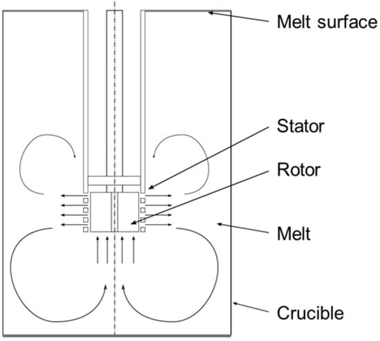
Figure 6.
Schematic diagram of the high shear melt conditioning (HSMC) process. Arrows without labels indicate the flow of molten metal during processing.
This section reviews recent progress on the application of HSMC to HPDC (MC-HPDC). In MC-HPDC, melt conditioning is performed in the holding furnace prior to die casting. When processing Al alloy melts, HSMC consists of two stages: degassing with Ar using the rotor-stator device, and then intensive shearing without Ar flow. The degassing efficiency of HSMC exceeds that of conventional methods, allowing for reduced Ar flow rates (0.2 lmin−1 [8]) compared to those used in rotary degassing (4 lmin−1 [8]). When treating Mg alloys, HSMC instead consists solely of intensive melt shearing under the protection of a suitable cover gas. After melt treatment, the alloy is transferred from the holding furnace into the shot sleeve of the die-casting machine, either manually using a transfer ladle or automatically using a dosing system. The melt delivery system must be carefully considered to retain the benefits of intensive melt shearing. Initial studies on MC-HPDC use a transfer ladle to manually transport molten metal into the shot sleeve, and despite this the benefits of HSMC are still evident. The development of suitable in-line processing techniques is, therefore, expected to play a key role in the quality control of die castings, and is the subject of ongoing work.
4.2. Grain Refinement of Mg Alloys Using Native MgO Particles
Zhang et al. [44] studied the as-cast microstructure and properties of AZ91D alloy produced by HPDC and MC-HPDC. Figure 7 shows the yield strength and tensile ductility of the AZ91D alloy produced with and without melt shearing. The average yield strength and tensile ductility of the AZ91D alloy increased from 127 MPa and 4.9% to 133 MPa and 5.8%, respectively, with intensive melt shearing. Moreover, the scatter in tensile ductility was greatly reduced after melt shearing, with values of 31.2% and 19.7% reported for the coefficient of variation (ratio of standard deviation to arithmetic mean) of specimens produced by HPDC and MC-HPDC, respectively.
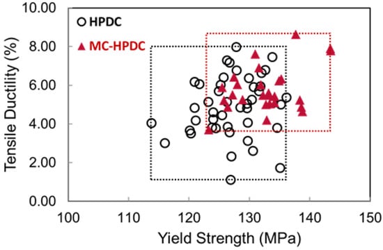
Figure 7.
Yield strength and tensile ductility of die-cast AZ91D alloy specimens produced with (MC-HPDC) and without (HPDC) melt shearing. Dotted lines show the range of the respective properties. Reprinted with permission from Ref. [44]. Copyright 2022, Elsevier.
Figure 8 shows the as-cast microstructure of die-cast AZ91D alloy produced with and without melt shearing. The as-cast microstructure of the AZ91D alloy consisted of large dendritic α-Mg1 grains, small globular-rosette α-Mg2 grains, and fine eutectic Mg17Al12 phase (Figure 8a). Intensive melt shearing was shown to induce a significant refinement of all three phases (Figure 8b and Table 1), which increased the yield strength and tensile ductility of the alloy (Figure 7). Scatter in tensile ductility, however, is primarily controlled by casting defects, such as porosity and defect bands [26,28]. Figure 8b,e show that the size of pores was greatly reduced with intensive melt shearing. Moreover, the maximum defect band thickness decreased by 40% after melt shearing (Figure 8c,f). These observations can be related to the rheology of the solidifying alloy and its response to shear deformation. Initial deformation of the semi-solid network is predominately affine, with an increase in shear stress accompanied by a volumetric expansion of the granular assembly (Reynold’s dilatancy) [29]. Dilatancy weakens the surrounding solid network, which promotes further deformation in that region, causing strain to localise along the shear plane. The negative pressures induced by dilatancy result in positive macro-segregation provided sufficient liquid can be drawn into the dilating band; interdendritic porosity follows when insufficient liquid is available for feeding. The maximum dilatational strain has been shown to increase with the solid fraction at which deformation takes place [30,31]. Moreover, the solid fraction is a strong function of grain size and shape. Grain refinement will, therefore, lead to a decrease in the maximum dilatational strain encountered during semi-solid deformation, reducing the size of pores and the thickness of defect bands. This in turn would lead to reduced scatter in tensile ductility (Figure 7).
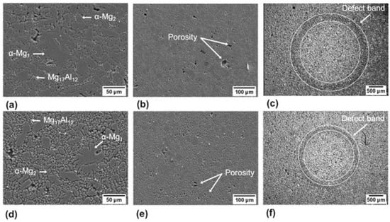
Figure 8.
SEM images of (a,d) primary α-Mg and eutectic Mg17A12 phases, (b,e) porosity, and (c,f) defect bands observed in die-cast microstructures produced by (a–c) HPDC and (d–f) MC-HPDC, respectively. Reprinted with permission from Ref. [44]. Copyright 2022, Elsevier.

Table 1.
Size of primary α-Mg1 grains, primary α-Mg2 grains, and eutectic Mg17Al12 phases observed in die-cast AZ91D alloys produced by HPDC and MC-HPDC [44].
To elucidate the mechanism of grain refinement by intensive melt shearing, Wang et al. [45] characterised native oxide films collected from Mg-9Al alloy melts using a pressure filtration technique. Native oxides in Mg alloys consist of discrete, densely populated MgO particles suspended in a liquid matrix (Figure 9a,b). These MgO particles are faceted crystals with two distinct morphologies: terminated octahedral and terminated cubic. Well-defined orientation relationships have been observed between MgO and α-Mg, demonstrating the potential to nucleate α-Mg on either the MgO or MgO surfaces [45,46,47]:
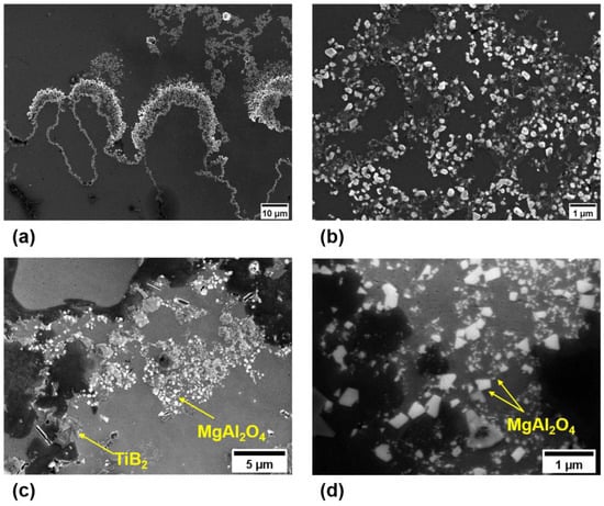
Figure 9.
Secondary electron images of native oxides in Al and Mg alloys. Oxides in both Al and Mg alloys consist of discrete nanoscale particles in a liquid matrix. Shown in (a,b) are MgO particles observed in a Mg-Al alloy [45]; shown in (c,d) are MgAl2O4 spinel particles collected from an Al-Si-Cu alloy [4].
The atomic configuration of the matching planes suggests a large lattice misfit of about 7.9% between MgO and α-Mg [45,46,47]. Moreover, ab initio molecular dynamics simulations [48] have shown that an atomically rough layer of Mg atoms forms at the interface between liquid Mg and solid MgO. The surface roughness and large lattice misfit with α-Mg make MgO and MgO substrates impotent for heterogeneous nucleation of α-Mg. However, MgO may still facilitate grain refinement in the absence of other, more potent substrates. Grain refinement depends on the interplay between heterogeneous nucleation and grain initiation. If the nucleation undercooling is less than that required for grain initiation on the largest substrate , then grain initiation occurs first on the largest substrate, and then on progressively smaller ones until recalescence. If , then grain initiation occurs explosively, with many grains initiating simultaneously at . Theoretical analysis [49] indicates that this latter, explosive mode of grain initiation may lead to more significant grain refinement under suitable experimental conditions.
Intensive melt shearing disperses native oxide films into discrete MgO particles, increasing the number of substrates available for heterogeneous nucleation. Moreover, the reduced size of substrates after melt shearing leads to an increased undercooling for grain initiation [50], which limits subsequent growth. The observed refinement of primary α-Mg grains with intensive melt shearing (Figure 8a,d) was, therefore, ascribed to the dispersion of native MgO particles and the use of these particles as heterogeneous nucleation substrates.
4.3. Precipitation Strengthening of Al-Si-Cu-Mg Alloys Using MgAl2O4 Spinel Particles
Intensive melt shearing also benefits the microstructure and properties of die-cast Al-Si-Cu-Mg alloys. Zhang et al. [4] studied the as-cast microstructure and mechanical properties of A380 alloy produced by HPDC and MC-HPDC. Intensive melt shearing was found to induce a refinement of both primary α-Al grains and the α-AlFeMnSi intermetallic phase nucleated in the shot sleeve. This in turn led to fewer casting defects and reduced scatter in tensile ductility. Grain refinement was attributed to the increased number density and reduced size of MgAl2O4 spinel particles after intensive melt shearing (Figure 9c,d). MgAl2O4 spinel has an octahedral morphology with facets. High-resolution transmission electron microscopy (HRTEM) [40] has revealed a small lattice misfit of about 1.4% between MgAl2O4 and α-Al along the orientation relationship MgAl2O4 α-Al. This demonstrates the potential to nucleate α-Al on the MgAl2O4 plane. Ab initio molecular dynamics simulations [51] have shown that a metallic layer develops at the interface between liquid Al and MgAl2O4. This metallic layer is chemically charged and structurally coupled to the substrate; it also contains atomic vacancies, making it somewhat rough. The surface roughness and small lattice misfit with α-Al make MgAl2O4 moderately potent for heterogeneous nucleation of α-Al. It is, therefore, reasonable to ascribe the grain refinement observed by Zhang et al. [4] to the increased number density and reduced size of MgAl2O4 spinel particles after intensive melt shearing.
Precipitation strengthening is an important strengthening mechanism that relies on the formation of nanoscale precipitates to impede dislocation motion. Suitable heat treatment is required to: (i) obtain a supersaturated solid solution; (ii) maintain the supersaturated status upon cooling; and (iii) precipitate secondary phase particles from the supersaturated solid solution. This generally involves a sequence of high temperature solution treatment, quenching, and low temperature aging. Die castings cannot normally undergo solution treatment and quenching due to the high risk of surface blistering and geometrical distortion. Another way to obtain a supersaturated solid solution is to inhibit atomic diffusion by rapid solidification at high cooling rates. The high cooling rates in HPDC (500–1000 Ks−1 [52]) may, therefore, enable direct aging of the as-cast material without the need for prior solution treatment and quenching. Zhang et al. [53] studied the aging behaviour of die-cast LM24 alloy produced with (LM24-M) and without intensive melt shearing. After T5 heat treatment (155 ± 5 °C for 15 h), the average yield strength of the LM24 alloy increased from 147 ± 3 MPa to 222 ± 3 MPa. Further strengthening was observed with the LM24-M alloy, for which the average yield strength increased from 169 ± 3 MPa to 297 ± 5 MPa after T5 treatment. For comparison, a yield strength of 280 MPa was reported for an Al-Si-Cu-Mg alloy after full heat treatment consisting of solutionising at 510 °C for 30 min, quenching in water, and aging at 170 °C for 24 h [54]. This demonstrated that the LM24-M alloy after direct aging could achieve the same level of yield strength as similar alloys after full heat treatment. Figure 10 shows TEM bright-field images and corresponding selected area electron diffraction (SAED) patterns for LM24-M alloy samples in the as-cast and T5 conditions. Many dislocations were observed in the as-cast condition, while no precipitates were detected in the SAED pattern (Figure 10a). In contrast, precipitates were readily observed in both the bright-field image and SAED pattern after T5 treatment (Figure 10b). Upon cooling from higher temperature, MgAl2O4 spinel particles act as dislocation sources due to the difference in thermal expansion coefficient between particle and matrix. Dislocations enhance precipitation kinetics by providing low energy channels for diffusing atoms and vacancies [55]. The increased volume fraction and reduced size of MgAl2O4 particles with intensive melt shearing would lead to a higher dislocation density in the as-cast material, which would facilitate precipitation upon subsequent aging. Figure 11a shows a low-magnification high-angle annular dark-field (HAADF) image of precipitates in the LM24-M alloy after T5 treatment, acquired via scanning transmission electron microscopy (STEM) [56]. Atomic resolution HAADF imaging and energy-dispersive X-ray spectroscopy (EDS) revealed the coexistence of two precipitates: θ’-Al2Cu (Figure 11b,c) and Si (Figure 11d–g). Contrary to previous reports [53], Q’-Al5Cu2Mg8Si6 precipitates were not observed in the LM24-M alloy. Si precipitates were found to possess two morphologies, one sphere-like and the other lath-like (Figure 11a). The sphere-like Si precipitates were very similar to those reported by Li et al. [57]. Interestingly, Cu and Zn were found to segregate to the interface between the Si precipitate and Al matrix (Figure 11e–g) [56]. For binary Al-Si alloys, Si has been reported to precipitate on Al with an incoherent interface [58]. Elemental segregation of Cu and Zn to the interface between Si and Al appeared to accommodate lattice misfit, allowing Si to precipitate on Al with a semi-coherent interface; this is in line with the observations of Mørtsell et al. [59]. Moreover, the segregation of Cu and Zn to the precipitate-matrix interface may inhibit precipitate growth [60]. The increased dislocation density due to the presence of MgAl2O4 particles and the growth restriction induced by the segregation of Cu and Zn to the precipitate-matrix interface would, therefore, lead to the formation of fine Si precipitates upon aging. This in turn would enhance the strength of the LM24-M alloy after T5 heat treatment. While this explanation may seem reasonable, no attempt was made to compare the relative effects of dislocation density and size-dependent supersaturation on the degree of precipitation strengthening in the LM24-M.
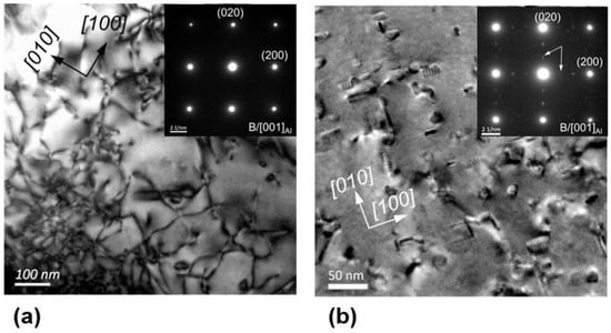
Figure 10.
TEM bright-field images and corresponding SAED patterns (insets) showing dislocations and precipitates in an Al-Si-Cu alloy prepared with intensive melt shearing. Dislocations are prevalent in the as-cast material (a), while many precipitates are observed after T5 aging treatment (b). Reprinted with permission from Ref. [53]. Copyright 2022, Elsevier.
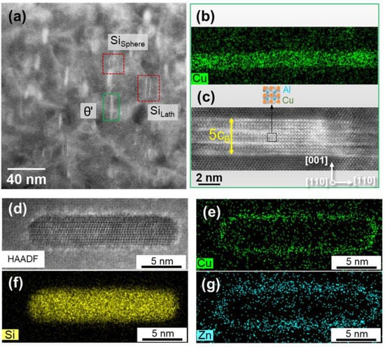
Figure 11.
STEM HAADF images and EDS analysis of precipitates found in the LM24-M alloy after T5 aging treatment. (a) Low-magnification HAADF image showing the coexistence of θ’-Al2Cu and Si precipitates. (b,c) EDS map and atomic resolution HAADF image of the θ’-Al2Cu precipitate highlighted in (a). (d–g) atomic resolution HAADF image and EDS maps of a lath-like Si precipitate acquired along the beam direction parallel to Al. Reprinted with permission from Ref. [56]. Copyright 2022, Elsevier.
5. Conclusions
- (1)
- Numerical modelling of the HPDC process was achieved using the finite element method (FEM) under the ProCAST (ESI Group) software platform. The model allowed complex phenomena—such as fluid flow, heat transfer and solidification—to be modelled in a detailed and timely manner. An overview of the modelling procedure is presented within, with references provided for further detail.
- (2)
- Variability in the tensile ductility of die castings was related to the size of large pores and non-metallic inclusions. It was proposed that these non-metallic inclusions formed during the pyrolysis of commercial plunger lubricants, and that these large pores derived from dilatational strains introduced during semi-solid deformation. By reducing heat loss in the shot sleeve, an optimised plunger speed profile was found to produce a more uniform grain structure, a decrease in the maximum pore size, and reduced variability in tensile ductility.
- (3)
- Fluid flow was found to have a significant influence on microstructural evolution and defect formation in HPDC. In a turbulent flow, large non-metallic inclusions were found to break down into more, smaller particles with a compact morphology. Increasing the turbulent energy dissipation rate was shown to promote breakage, leading to an increase in tensile strength and tensile ductility. An increase in the dissipation rate of turbulent kinetic energy was also accompanied by a refinement of large primary -Al1 grains nucleated in the shot sleeve. Grain refinement was attributed to the fragmentation of incipient grains due to turbulent oscillations of the surrounding thermal and compositional fields.
- (4)
- Intensive melt shearing was found to induce significant grain refinement in die-cast Al and Mg alloys, which led to fewer casting defects and reduced scatter in tensile ductility. Grain refinement was ascribed to the effective dispersion of native oxide particles, and the use of these particles as heterogeneous nucleation substrates. The presence of native oxide particles led to an increased dislocation density in the as-cast material, which enhanced precipitation kinetics during subsequent aging treatment. The improvement in yield strength observed for the alloy containing oxide particles after direct aging was comparable to that observed for similar alloys after full solution heat treatment.
Author Contributions
Conceptualization, E.L., Y.Z., K.D., A.J. and Z.F.; methodology, E.L., Y.Z., K.D., A.J., C.T., S.W., Y.W., J.L.-N., J.P., X.Z. and T.H. ; software, K.D. and A.J.; validation, E.L. and Y.Z.; formal analysis, E.L., Y.Z., K.D., S.W., C.T., X.Z., T.H. and Y.W. ; investigation, E.L., Y.Z., K.D., A.J. and J.P.; resources, Z.F. and X.Z.; data curation, E.L., Y.Z., K.D., C.T., S.W., Y.W., J.L.-N., J.P. and T.H.; writing—original draft preparation, E.L., Y.Z., K.D. and S.W.; writing—review and editing, E.L. and Z.F.; visualization, E.L., Y.Z., K.D., S.W., C.T. and J.L.-N.; supervision, A.J. and Z.F.; project administration, Z.F.; funding acquisition, Z.F. All authors have read and agreed to the published version of the manuscript.
Funding
This research was funded by the Engineering and Physical Sciences Research Council (EPSRC) and Jaguar Land Rover Ltd. as part of the EPSRC Future Liquid Metal Engineering (LiME) Hub (grant number: 2043200). The APC was funded by Brunel University London.
Data Availability Statement
The datasets generated and analysed during the current study are available from the corresponding author on reasonable request.
Acknowledgments
The authors gratefully acknowledge the contributions of Jon Gadd and Peter Lloyd to the experimental method.
Conflicts of Interest
The authors declare no conflict of interest.
References
- Niu, X.P.; Tong, K.K.; Hu, B.H.; Pinwill, I. Cavity pressure sensor study of the gate freezing behaviour in aluminium high pressure die casting. Int. J. Cast Met. Res. 1998, 11, 105–112. [Google Scholar] [CrossRef]
- Dong, X.; Zhu, X.; Ji, S. Effect of super vacuum assisted high pressure die casting on the repeatability of mechanical properties of Al-Si-Mg-Mn die-cast alloys. J. Mater. Process. Technol. 2019, 266, 105–113. [Google Scholar] [CrossRef]
- Ji, S.; Yang, H.; Watson, D.; Fan, Z. Weibull Analysis for the Repeatibility of Die Castings Made by an Al-Mg-Si-Mn Alloy. TMS Light Met. 2016, 681–685. [Google Scholar] [CrossRef]
- Zhang, Y.; Patel, J.B.; Lazaro-Nebreda, J.; Fan, Z. Improved Defect Control and Mechanical Property Variation in High-Pressure Die Casting of A380 Alloy by High Shear Melt Conditioning. JOM 2018, 70, 2726–2730. [Google Scholar] [CrossRef]
- Lordan, E.; Lazaro-Nebreda, J.; Zhang, Y.; Dou, K.; Blake, P.; Fan, Z. On the relationship between internal porosity and the tensile ductility of aluminium alloy die-castings. Mater. Sci. Eng. A 2020, 778, 139107. [Google Scholar] [CrossRef]
- Weiler, J.; Wood, J. Modeling fracture properties in a die-cast AM60B magnesium alloy I—Analytical failure model. Mater. Sci. Eng. A 2009, 527, 25–31. [Google Scholar] [CrossRef]
- Weiler, J.; Wood, J.; Klassen, R.; Maire, E.; Berkmortel, R.; Wang, G. Relationship between internal porosity and fracture strength of die-cast magnesium AM60B alloy. Mater. Sci. Eng. A 2005, 395, 315–322. [Google Scholar] [CrossRef]
- Lordan, E.; Lazaro-Nebreda, J.; Zhang, Y.; Fan, Z. Effective Degassing for Reduced Variability in High-Pressure Die Casting Performance. JOM 2019, 71, 824–830. [Google Scholar] [CrossRef]
- Tian, C.; Law, J.; van der Touw, J.; Murray, M.; Yao, J.-Y.; Graham, D.; John, D.S. Effect of melt cleanliness on the formation of porosity defects in automotive aluminium high pressure die castings. J. Mater. Process. Technol. 2002, 122, 82–93. [Google Scholar] [CrossRef]
- Ferraro, S.; Timelli, G. Influence of Sludge Particles on the Tensile Properties of Die-Cast Secondary Aluminum Alloys. Met. Mater. Trans. A 2015, 46, 1022–1034. [Google Scholar] [CrossRef]
- Timelli, G.; Fabrizi, A. The Effects of Microstructure Heterogeneities and Casting Defects on the Mechanical Properties of High-Pressure Die-Cast AlSi9Cu3(Fe) Alloys. Met. Mater. Trans. A 2014, 45, 5486–5498. [Google Scholar] [CrossRef]
- Ji, S.; Yang, W.; Gao, F.; Watson, D.; Fan, Z. Effect of iron on the microstructure and mechanical property of Al–Mg–Si–Mn and Al–Mg–Si diecast alloys. Mater. Sci. Eng. A 2013, 564, 130–139. [Google Scholar] [CrossRef]
- Li, X.; Xiong, S.; Guo, Z. On the porosity induced by externally solidified crystals in high-pressure die-cast of AM60B alloy and its effect on crack initiation and propagation. Mater. Sci. Eng. A 2015, 633, 35–41. [Google Scholar] [CrossRef]
- Gjestland, H.; Sannes, S.; Svalestuen, J.; Westengen, H. Optimizing the Magnesium Die Casting Process to Achieve Reliability in Automotive Applications. SAE Int. J. Transp. Saf. 2005, 114, 67–73. [Google Scholar]
- Li, X.; Xiong, S.; Guo, Z. Improved mechanical properties in vacuum-assist high-pressure die casting of AZ91D alloy. J. Mater. Process. Technol. 2016, 231, 1–7. [Google Scholar] [CrossRef]
- Li, X.; Yu, W.; Wang, J.; Xiong, S. Influence of melt flow in the gating system on microstructure and mechanical properties of high pressure die casting AZ91D magnesium alloy. Mater. Sci. Eng. A 2018, 736, 219–227. [Google Scholar] [CrossRef]
- Gunasegaram, D.R.; Givord, M.; O’Donnell, R.G.; Finnin, B.R. Improvements engineered in UTS and elongation of aluminum alloy high pressure die castings through the alteration of runner geometry and plunger velocity. Mater. Sci. Eng. A 2013, 559, 276–286. [Google Scholar] [CrossRef]
- Saeedipour, M.; Schneiderbauer, S.; Pirker, S.; Bozorgi, S. A Numerical and Experimental Study of Flow Behavior in High Pressure Die Casting. Magnes. Tech. 2014, 185–190. [Google Scholar] [CrossRef]
- Dou, K.; Lordan, E.; Zhang, Y.J.; Jacot, A.; Fan, Z.Y. Numerical simulation of fluid flow, solidification and defects in high pressure die casting (HPDC) process. IOP Conf. Ser. Mater. Sci. Eng. 2019, 529, 012058. [Google Scholar] [CrossRef]
- Vinarcik, E.J. Vinarcik. High-Integrity Die Casting Processes; John Wiley & Sons: Hoboken, NJ, USA, 2003. [Google Scholar]
- Dou, K.; Lordan, E.; Zhang, Y.; Jacot, A.; Fan, Z. A novel approach to optimize mechanical properties for aluminium alloy in High pressure die casting (HPDC) process combining experiment and modelling. J. Mater. Process. Technol. 2021, 296, 117193. [Google Scholar] [CrossRef]
- Dou, K.; Lordan, E.; Zhang, Y.; Jacot, A.; Fan, Z. A complete computer aided engineering (CAE) modelling and optimization of high pressure die casting (HPDC) process. J. Manuf. Process. 2020, 60, 435–446. [Google Scholar] [CrossRef]
- Vakhrushev, A.; Ludwig, A.; Wu, M.; Tnag, Y.; Nitzl, G.; Hackl, G. Modeling of Turbulent Melt Flow and Solidification Processes in Steel Continuous Caster with the Open Source Software Package OpenFOAM. In 2010 OSC Annual Report—Ontario Securities Commission; The Ontario Securities Commission (OSC): Munich, Germany, 2010; pp. 4–5. [Google Scholar]
- Elghobashi, S.E.; Abou-Arab, T.W. A two-equation turbulence model for two-phase flows. Phys. Fluids 1983, 26, 931. [Google Scholar] [CrossRef]
- Pequet, C.; Rappaz, M.; Gremaud, M. Modeling of microporosity, macroporosity, and pipe-shrinkage formation during the solidification of alloys using a mushy-zone refinement method: Applications to aluminum alloys. Met. Mater. Trans. A 2002, 33, 2095–2106. [Google Scholar] [CrossRef]
- Lordan, E.; Zhang, Y.; Dou, K.; Jacot, A.; Tzileroglou, C.; Blake, P.; Fan, Z. On the probabilistic nature of high-pressure die casting. Mater. Sci. Eng. A 2021, 817, 141391. [Google Scholar] [CrossRef]
- Su, T.; O’Sullivan, C.; Nagira, T.; Yasuda, H.; Gourlay, C. Semi-solid deformation of Al-Cu alloys: A quantitative comparison between real-time imaging and coupled LBM-DEM simulations. Acta Mater. 2019, 163, 208–225. [Google Scholar] [CrossRef]
- Gourlay, C.M.; Laukli, H.I.; Dahle, A.K. Defect Band Characteristics in Mg-Al and Al-Si High-Pressure Die Castings. Met. Mater. Trans. A 2007, 38, 1833–1844. [Google Scholar] [CrossRef]
- Gourlay, C.M.; Dahle, A.K. Dilatant shear bands in solidifying metals. Nature 2007, 445, 70–73. [Google Scholar] [CrossRef]
- Kareh, K.M.; Lee, P.D.; Atwood, R.C.; Connolley, T.; Gourlay, C.M. Pore behaviour during semi-solid alloy compression: Insights into defect creation under pressure. Scr. Mater. 2014, 89, 73–76. [Google Scholar] [CrossRef]
- Kareh, K.M.; Lee, P.D.; Atwood, R.C.; Connolley, T.; Gourlay, C.M. Revealing the micromechanisms behind semi-solid metal deformation with time-resolved X-ray tomography. Nat. Commun. 2014, 5, 4464. [Google Scholar] [CrossRef]
- Lordan, E.; Dou, K.; Zhang, Y.; Tzileroglou, C.; Jacot, A.; Blake, P.; Fan, Z. Turbulent breakup of non-metallic inclusions and equiaxed crystals during solidification of a hypoeutectic Al-Si alloy. Materialia 2021, 17, 101114. [Google Scholar] [CrossRef]
- Otarawanna, S.; Gourlay, C.M.; Laukli, H.I.; Dahle, A.K. Microstructure Formation in AlSi4MgMn and AlMg5Si2Mn High-Pressure Die Castings. Met. Mater. Trans. A 2009, 40, 1645–1659. [Google Scholar] [CrossRef]
- Shu, D.; Sun, B.; Mi, J.; Grant, P. A High-Speed Imaging and Modeling Study of Dendrite Fragmentation Caused by Ultrasonic Cavitation. Met. Mater. Trans. A 2012, 43, 3755–3766. [Google Scholar] [CrossRef]
- Ruvalcaba, D.; Mathiesen, R.; Eskin, D.; Arnberg, L.; Katgerman, L. In situ observations of dendritic fragmentation due to local solute-enrichment during directional solidification of an aluminum alloy. Acta Mater. 2007, 55, 4287–4292. [Google Scholar] [CrossRef]
- Mathiesen, R.H.; Arnberg, L.; Bleuet, P.; Somogyi, A. Crystal fragmentation and columnar-to-equiaxed transitions in Al-Cu studied by synchrotron X-ray video microscopy. Met. Mater. Trans. A 2006, 37, 2515–2524. [Google Scholar] [CrossRef]
- Vogel, A. Turbulent flow and solidification: Stir-cast microstructure. Met. Sci. 1978, 12, 576–578. [Google Scholar] [CrossRef]
- Doherty, R.D.; Lee, H.-I.; Feest, E.A. Microstructure of stir-cast metals. Mater. Sci. Eng. 1984, 65, 181–189. [Google Scholar] [CrossRef]
- Liotti, E.; Lui, A.; Vincent, R.; Kumar, S.; Guo, Z.; Connolley, T.; Dolbnya, I.P.; Hart, M.; Arnberg, L.; Mathiesen, R.H.; et al. A synchrotron X-ray radiography study of dendrite fragmentation induced by a pulsed electromagnetic field in an Al–15Cu alloy. Acta Mater. 2014, 70, 228–239. [Google Scholar] [CrossRef]
- Li, H.-T.; Wang, Y.; Fan, Z. Mechanisms of enhanced heterogeneous nucleation during solidification in binary Al–Mg alloys. Acta Mater. 2012, 60, 1528–1537. [Google Scholar] [CrossRef]
- Li, H.T.; Xia, M.; Jarry, P.; Scamans, G.; Fan, Z. Grain refinement in a AlZnMgCuTi alloy by intensive melt shearing: A multi-step nucleation mechanism. J. Cryst. Growth 2011, 314, 285–292. [Google Scholar] [CrossRef]
- Fan, Z.; Wang, Y.; Xia, M.; Arumuganathar, S. Enhanced heterogeneous nucleation in AZ91D alloy by intensive melt shearing. Acta Mater. 2009, 57, 4891–4901. [Google Scholar] [CrossRef]
- Özcan-Taşkın, N.G.; Padron, G.; Kubicki, D. Comparative performance of in-line rotor-stators for deagglomeration processes. Chem. Eng. Sci. 2016, 156, 186–196. [Google Scholar] [CrossRef]
- Zhang, Y.; Patel, J.; Wang, Y.; Fan, Z. Variation improvement of mechanical properties of Mg-9Al-1Zn alloy with melt conditioned high pressure die casting. Mater. Charact. 2018, 144, 498–504. [Google Scholar] [CrossRef]
- Wang, S.; Wang, Y.; Ramasse, Q.; Fan, Z. The Nature of Native MgO in Mg and Its Alloys. Met. Mater. Trans. A 2020, 51, 2957–2974. [Google Scholar] [CrossRef]
- Wang, Y.; Li, H.-T.; Fan, Z. Grain Refinement of Al- and Mg- alloys by Native Oxide Particles. In Proceedings of the 6th Decennial International Conference on Solidification Processing (SP17), Old Windsor, UK, 25–27 July 2017; pp. 81–86. [Google Scholar]
- Wang, Y.; Fan, Z.; Zhou, X.; Thompson, G.E. Characterisation of magnesium oxide and its interface with α-Mg in Mg–Al-based alloys. Philos. Mag. Lett. 2011, 91, 516–529. [Google Scholar] [CrossRef]
- Fang, C.M.; Fan, Z. Prenucleation at the Interface Between MgO and Liquid Magnesium: An Ab Initio Molecular Dynamics Study. Met. Mater. Trans. A 2020, 51, 788–797. [Google Scholar] [CrossRef]
- Fan, Z.; Gao, F.; Jiang, B.; Que, Z. Impeding Nucleation for More Significant Grain Refinement. Sci. Rep. 2020, 10, 9448. [Google Scholar] [CrossRef]
- Greer, A.L.; Bunn, A.M.; Tronche, A.; Evans, P.V.; Bristow, D.J. Modelling of inoculation of metallic melts: Application to grain refinement of aluminium by Al–Ti–B. Acta Mater. 2000, 48, 2823–2835. [Google Scholar] [CrossRef]
- Fang, C.M.; Fan, Z. Atomic Ordering at the Liquid-Al/MgAl2O4 Interfaces from Ab Initio Molecular Dynamics Simulations. Met. Mater. Trans. A 2020, 51, 6318–6326. [Google Scholar] [CrossRef]
- dos Santos, S.L.; Antunes, R.A.; Santos, S.F. Influence of injection temperature and pressure on the microstructure, mechanical and corrosion properties of a AlSiCu alloy processed by HPDC. Mater. Des. 2015, 88, 1071–1081. [Google Scholar] [CrossRef]
- Zhang, Y.; Wang, S.; Lordan, E.; Wang, Y.; Fan, Z. Improve mechanical properties of high pressure die cast Al9Si3Cu alloy via dislocation enhanced precipitation. J. Alloy. Compd. 2019, 785, 1015–1022. [Google Scholar] [CrossRef]
- Yang, H.; Ji, S.; Yang, W.; Wang, Y.; Fan, Z. Effect of Mg level on the microstructure and mechanical properties of die-cast Al–Si–Cu alloys. Mater. Sci. Eng. A 2015, 642, 340–350. [Google Scholar] [CrossRef]
- Legros, M.; Dehm, G.; Arzt, E.; Balk, T.J. Observation of Giant Diffusivity Along Dislocation Cores. Science 2008, 319, 1646–1649. [Google Scholar] [CrossRef] [PubMed]
- Zhang, Y.; Wang, S.; Lordan, E.; Dou, K.; Zhou, X.; Hashimoto, T. Understanding of surface segregation of Cu and Zn on nano Si precipitates to the mechanical property improvement of high pressure die casting Al9Si3CuFe alloy. J. Alloy. Compd. 2021, 895, 162219. [Google Scholar] [CrossRef]
- Li, X.; Ji, G.; Chen, Z.; Addad, A.; Wu, Y.; Wang, H.; Vleugels, J.; Van Humbeeck, J.; Kruth, J. Selective laser melting of nano-TiB2 decorated AlSi10Mg alloy with high fracture strength and ductility. Acta Mater. 2017, 129, 183–193. [Google Scholar] [CrossRef]
- Lasagni, F.; Mingler, B.; Dumont, M.; Degischer, H.P. Precipitation kinetics of Si in aluminium alloys. Mater. Sci. Eng. A 2008, 480, 383–391. [Google Scholar] [CrossRef]
- Mørtsell, E.A.; Qian, F.; Marioara, C.D.; Li, Y. Precipitation in an A356 foundry alloy with Cu additions—A transmission electron microscopy study. J. Alloy. Compd. 2019, 785, 1106–1114. [Google Scholar] [CrossRef]
- Liu, M.; Zheng, R.; Xiao, W.; Yu, X.; Peng, Q.; Ma, C. Concurrent enhancement of strength and ductility for Al-Si binary alloy by refining Si phase to nanoscale. Mater. Sci. Eng. A 2019, 751, 303–310. [Google Scholar] [CrossRef]
Publisher’s Note: MDPI stays neutral with regard to jurisdictional claims in published maps and institutional affiliations. |
© 2022 by the authors. Licensee MDPI, Basel, Switzerland. This article is an open access article distributed under the terms and conditions of the Creative Commons Attribution (CC BY) license (https://creativecommons.org/licenses/by/4.0/).