Article

Investigation of the Interfacial Characteristics and Mechanical Properties of Duplex Stainless Steel/Low-Alloy Steel Clad Rebar

1
Metallurgical Technology Institute, Central Iron and Steel Research Institute, Beijing 100081, China
2
Ansteel Beijing Research Institute Co., Ltd., Beijing 102200, China
3
Xingtai Iron and Steel Co., Ltd., Xingtai 054000, China
*
Author to whom correspondence should be addressed.
Metals 2022, 12(10), 1573; https://doi.org/10.3390/met12101573
Submission received: 4 August 2022 / Revised: 7 September 2022 / Accepted: 14 September 2022 / Published: 22 September 2022

Abstract

:
In this work, duplex stainless steel/low-alloy steel-clad rebars were fabricated using metal deposition and hot rolling. The interfacial characteristics of the rebar, such as element diffusion and phase composition, were investigated using an optical microscope and a scanning electron microscope with an energy-dispersive spectrometer. The mechanical properties of the rebar were evaluated by tensile and bending tests. The results show that the rebar interface is composed of a carburized layer on the duplex stainless steel side and a decarburized layer on the low-alloy steel side; they also show that the rebar exhibits good mechanical properties, with 435 MPa of yield strength, 630 MPa of tensile strength, and a 24.8% percentage elongation. The reduction in the cladding thickness at the rebar’s transverse rib root was studied using the ABAQUS software. The results show that the cladding thickness is reduced due to the effect of the groove shape during the rolling process. The rebar’s transverse rib root cracked after bending due to the thinning of the cladding and brittle fractures in the interfacial martensite layer.

1. Introduction

As early as the Song Dynasty (1270 A.D.), bimetallic composites were used to make weapons in China. In those days, a high carbon blade was sandwiched in a wrought iron knife body to obtain good levels of hardness and toughness. Nowadays, with the development of science, the challenge of optimizing novel bulk materials has gradually changed to that of synthesizing compounds that contain metallurgical joints [1]. Stainless steel cladding materials, which have the advantage of combining the excellent formability, weldability, and thermal conductivity of carbon steel with the high corrosion resistance, abrasion resistance, and heat resistance of stainless steel, are widely used in the field of nuclear power equipment, the petrochemical industry, the automobile industry, and so on [2,3]. So far, various techniques have already been used to produce cladding materials, such as explosive welding, vacuum hot rolling, extrusion compounding, horizontal twin-roll casting, spray deposition, etc.
A vessel steel/duplex stainless steel cladding plate was fabricated by explosive welding; it had higher impact toughness and corrosion properties than the base material due to the cladding material of duplex stainless steel [4]. Lee et al. [5] investigated the influence of processing conditions on the homogeneity and thickness of the interface layer and the overall strength of the Zr/Cu rod fabricated by co-extrusion. In 2016, Chen et al. [6] produced a stainless steel/aluminium clad plate by horizontal twin-roll casting and investigated the interface morphology of the clad plate after different annealing and cold rolling processes. Zhao et al. [7] designed a cold spray additive to fabricate titanium/steel-clad plates. However, these methods have various shortcomings. For instance, explosive welding can easily cause interface instability, resulting in poor interfacial bonding [8]. Extrusion compounding is generally used to prepare small-format products due to the die’s scale limitations. Horizontal twin-roll casting is suitable for compounding metals with low and high melting points, but not for refractory metals. Although roll bonding is a common method, it results in the formation of oxides and voids at the interface [7]. In order to solve this problem, researchers have used vacuum rolling to prepare cladding materials [9,10,11,12,13,14], which increases production costs.
In recent years, the cladding plate has been extensively studied; meanwhile, research into clad rebars, an important part of infrastructure projects, is rarely reported. In addition, the cladding structures of a plate and rebar are obviously different. In general, the upper and lower surfaces of the plate are cladded with dissimilar metals, while the bar needs to be cladded with dissimilar metals on all surfaces except the end face. Therefore, the clad bar is usually prepared by perforation and hot extrusion; using this method, Gutiérrez et al. [15] prepared a seamless clad tube in the 1990s. However, the sealing procedures of such assemblies are relatively complex. In this paper, metal deposition and hot rolling were used to fabricate a duplex stainless steel/low-alloy steel-(DSS/LAS) clad rebar to simplify the sealing procedures of these assemblies. In addition, the effect of the reduction ratio on the thickness and element diffusion of the martensite layer is further analyzed in this work. Compared with ordinary stainless steel, the DSS has not only excellent toughness and high strength but also excellent chloride corrosion resistance. Therefore, the DSS/LAS-clad rebar has the potential to be applied widely in marine engineering. The present work aims to investigate the interfacial characteristics and mechanical properties of the DSS/LAS-clad rebar to provide a theoretical and technological foundation for fabricating the DSS/LAS-clad rebar by metal deposition and hot rolling.

2. Experimental

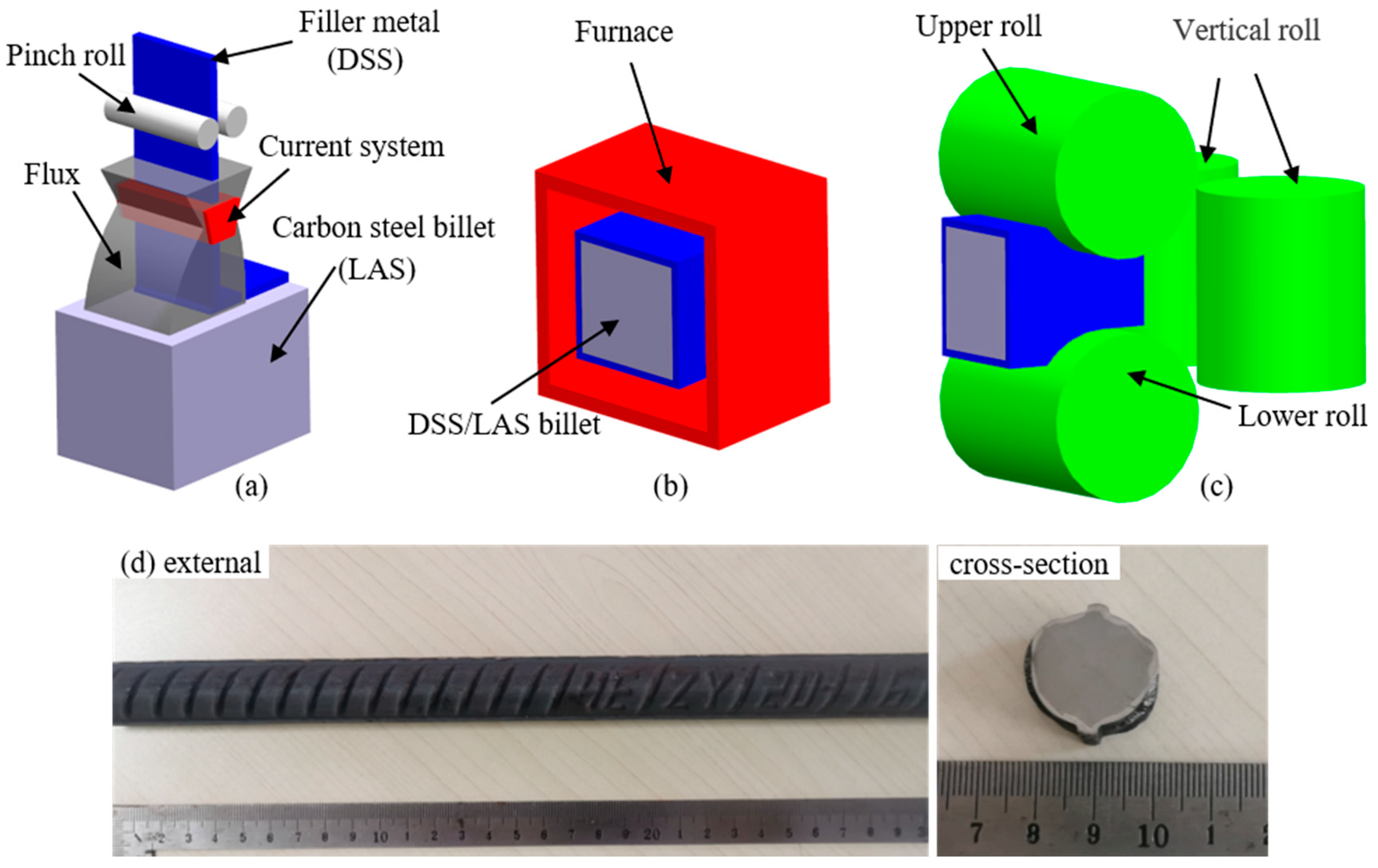
2.1. Materials and Method

The DSS/LAS-clad rebars were successfully fabricated by cladding the DSS with corrosion resistance and oxidation resistance on the LAS with good mechanical properties and impact resistance. The chemical compositions of these components are presented in Table 1.
The dimensions of the LAS billet are 150 mm × 150 mm × 6000 mm, and a 5 mm-thick layer of stainless steel was deposited on its four surfaces. The cladded surfaces were carefully cleaned using a wire brush and an angle grinder before depositing, because a clean interface ensures the consistent quality of cladding materials [12]. The deposition metal was melted by the current system and then deposited on the LAS billet. During processing, flux ensures bonding strength at the interface and avoids oxidation. Carbides in duplex stainless steel precipitate in the temperature range of 773 K to 1273 K, affecting the steel’s corrosion resistance. Therefore, the DSS/LAS billet was soaked at 1453 K for 3 h after depositing. At the same time, this also ensured the initial and final rolling temperatures, in order to inhibit the precipitation of carbides in the DSS. Then, hot rolling was carried out through 15 passes, and the DSS/LAS billet was reduced from a rectangular section (160 mm × 160 mm) down to a circular section (Φ20 mm). The reduction ratio was 98.8%. The initial and the final rolling temperatures were 1403 K and 1373 K, respectively. Finally, the DSS/LAS-clad rebar was cooled in the air. The DSS/LAS-clad rebar production process is shown in Figure 1.

2.2. Microstructure Observations

Microstructures were observed using the optical microscope (OM) (OLYMPUS, Tokyo, Japan). Metallographic samples were cut from the DSS/LAS billet and rebar, and then these samples were ground, polished, and etched. The side of the DSS was electrolyzed using a 10% chromic acid with a constant potential voltage of 5 V for 20 s, and the side of the LAS was etched by soaking it in a 4% ethanol solution of nitric acid for 10 s. The diffusion phenomenon of elements was analyzed using a Quant 650-FEG scanning electron microscope (SEM) (FEI Corp., Hillsborough, OR, USA) with an energy-dispersive spectrometer (EDS) to research the effect of elemental diffusion on microstructure evolution.

2.3. Testing of Mechanical Properties

In order to further study the microstructural characteristics of the DSS/LAS billet and rebar, Vickers microhardness was measured using an FM-300 Vickers hardness tester (FUTURE-TECH Corp., Tokyo, Japan) under a 200 g load for 10 s. The strength and ductility of the DSS/LAS-clad rebar were measured using a WAW-500 universal testing machine (hensgrand, Shandong, China) with an average loading rate of 10.37 kN/s at room temperature. Mean values were calculated from five individual tensile tests. The length of the tensile samples was 500 mm; to avoid losing the cladding layer, they were not machined into dumbbell samples. Fracture morphology was observed using SEM after the tensile specimens were fractured. Bending experiments were performed at room temperature to investigate the formability of the DSS/LAS-clad rebar according to Chinese national standard GB/T 1499.2-2018, in which the samples are bent 180° by an indenter with a diameter of 80 mm. The specimens were cut along the axial direction after bending, and then longitudinal sections were ground, polished, and etched to observe the interface bonding between the DSS and LAS during bending.

3. Results and Discussion

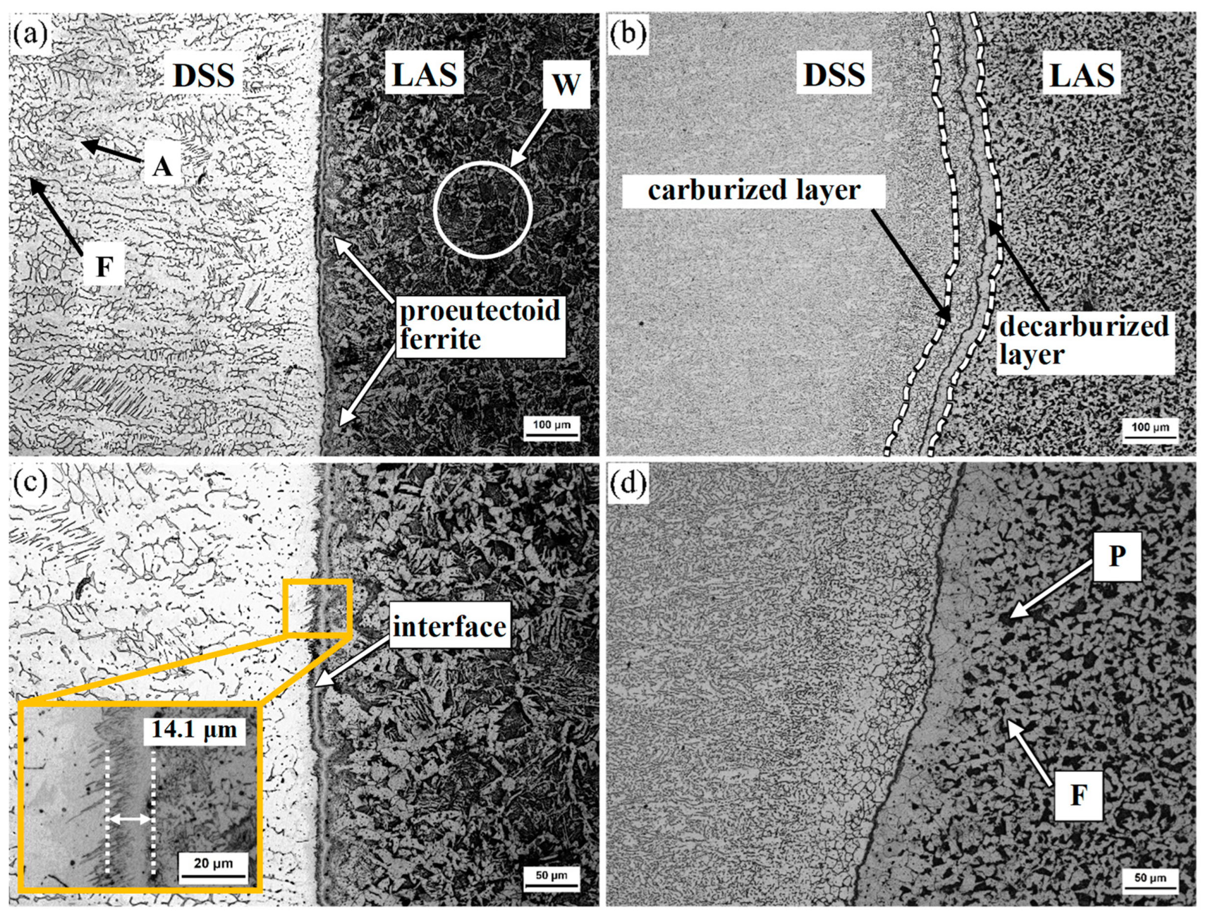
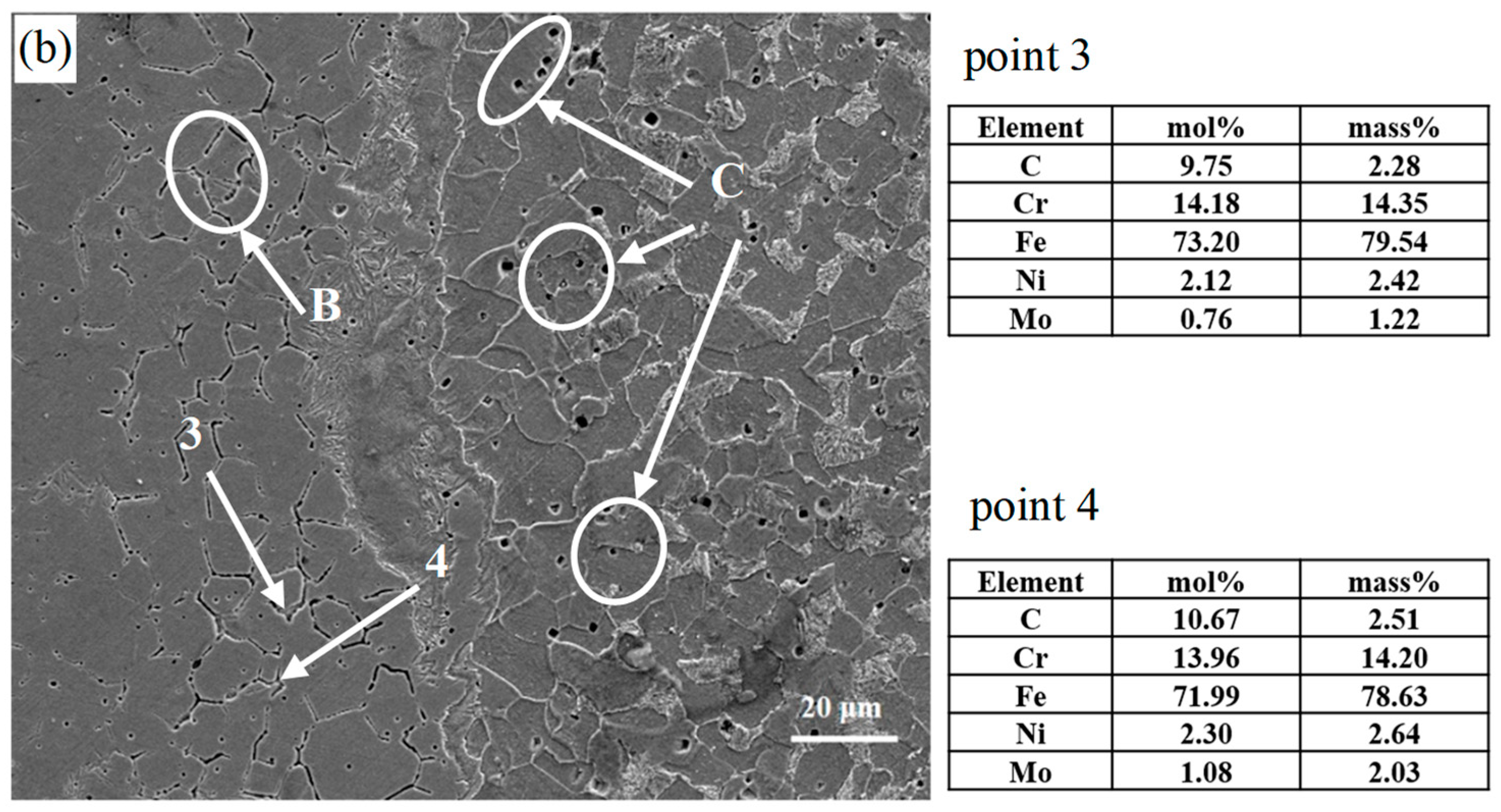
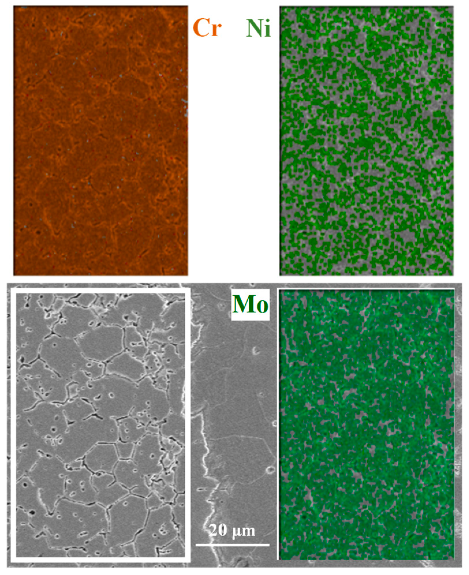
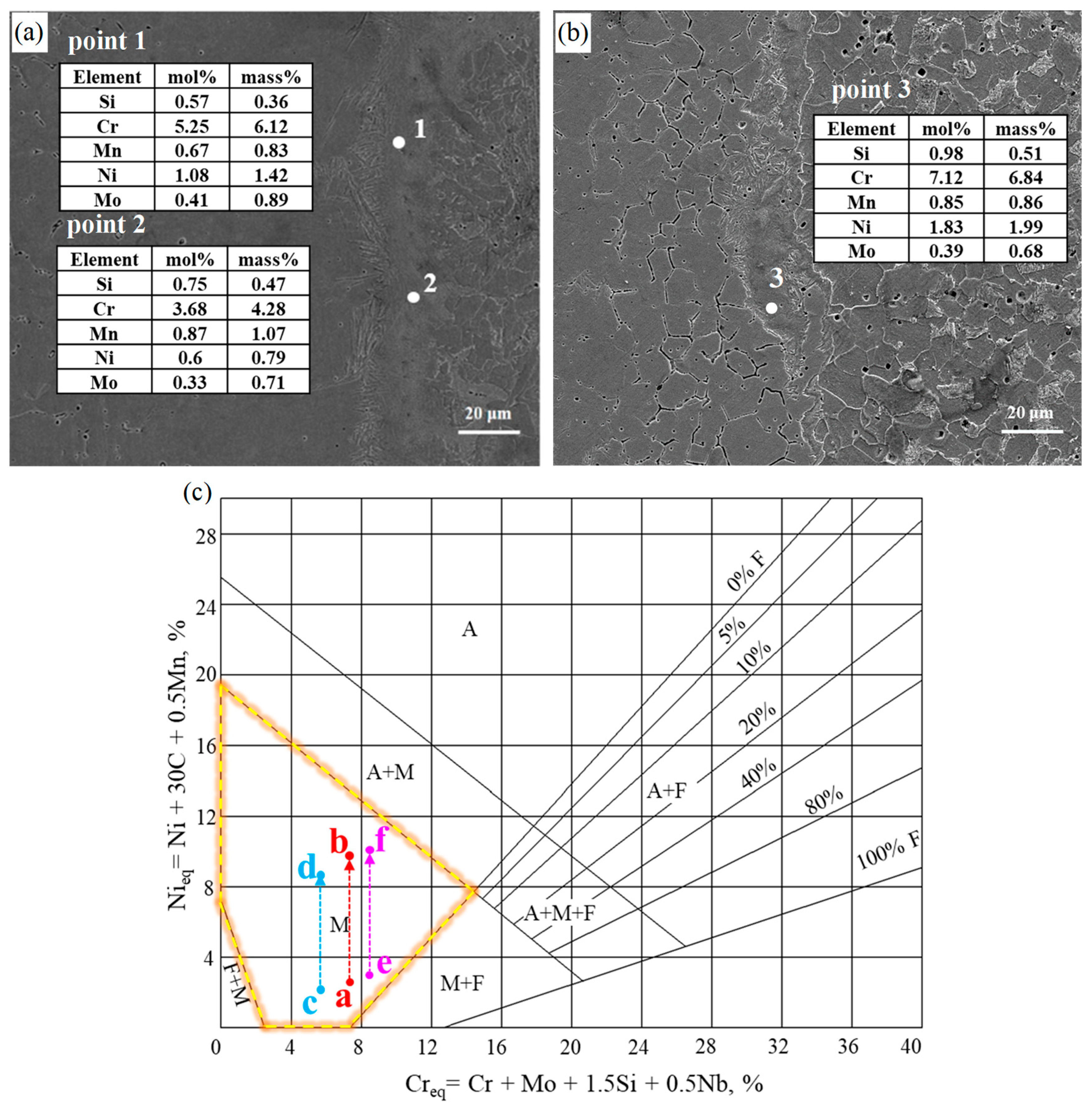
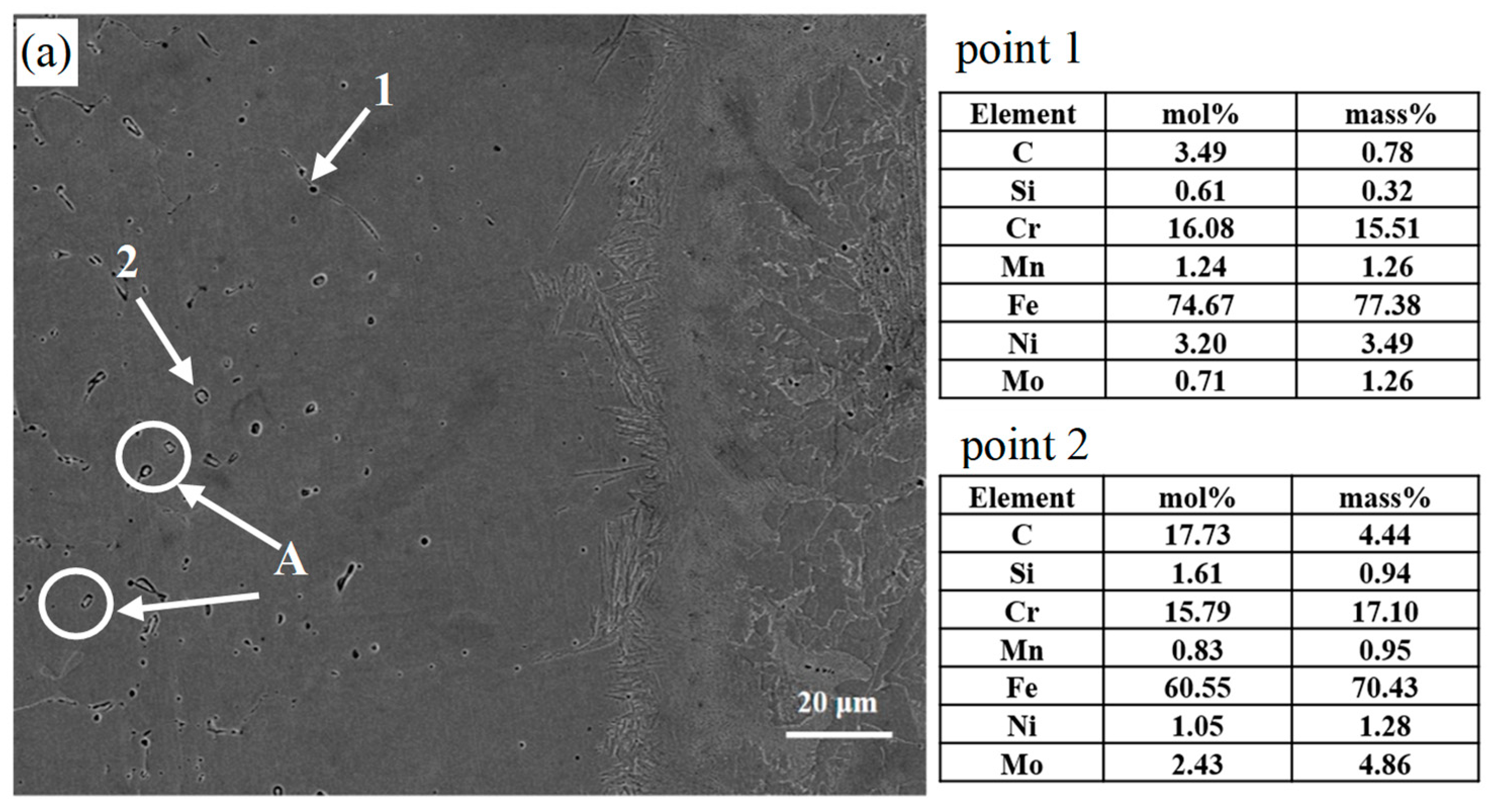
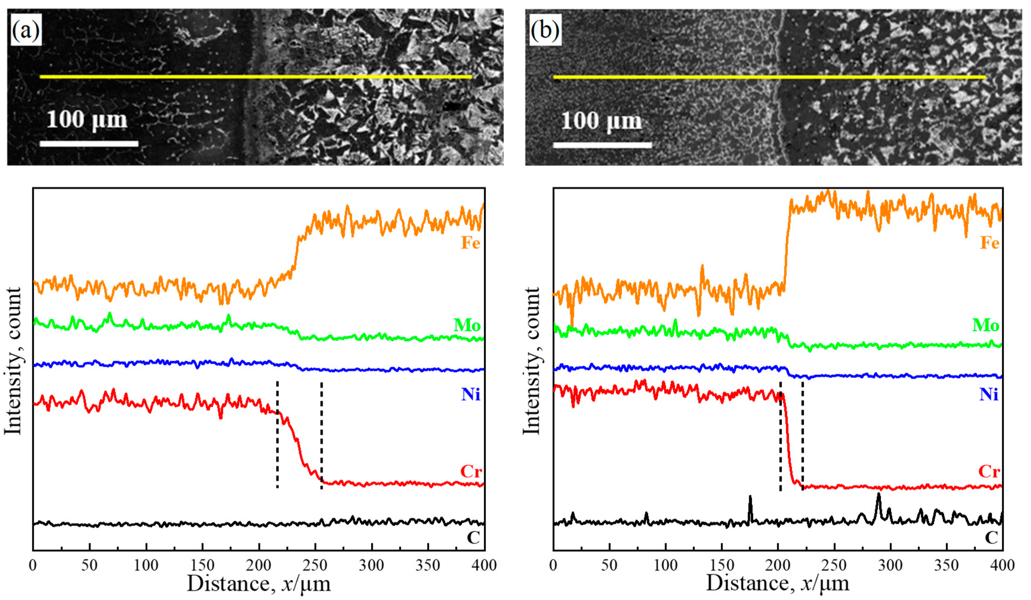
3.1. Effect of Element Diffusion on the Evolution of the Microstructure

Figure 2 shows the microstructure of the DSS/LAS-clad rebar before and after rolling. We can clearly observe the two-phase structure of ferrite (F, dark black) and austenite (A, light grey) in the DSS, and the Widmanstӓtten (W) structure in the as-deposited LAS, as shown in Figure 2a. After the deposition, proeutectoid ferrite near the interface precipitated before eutectoid transformation. Subsequently, the Widmanstӓtten structure formed on the LAS side because of the high austenitizing temperature and relatively high cooling rate [16]. Compared with the as-deposited, the microstructure of the DSS was significantly refined due to a higher reduction ratio, and Widmanstӓtten was transformed into ferrite (light grey) plus pearlite (dark black) on the LAS side, as presented in Figure 2b. In addition, a carburized layer with a thickness of ~51.7 μm and a decarburized layer with a thickness of ~43.3 μm are located at the interface zone, which can be attributed to the diffusion of C atoms [17]. The thickness of the carburized layer is thicker than that of the decarburized layer, resulting from the long-range diffusion of C atoms. Meanwhile, a single-phase austenite region formed in the carburized layer, as shown in Figure 2d, because C promotes austenite formation. This is in agreement with the research conducted by M. Yan et al. [18]. Moreover, we observe remarkable gradient grain distribution on the LAS side: that is, coarse ferrite in a decarburized layer near the interface and fine pearlite (P) far away from the interface, as shown in Figure 2d. This is because pearlite can stimulate ferrite nucleation during the cooling process [11]. An interface with a needle-like strip structure is shown in Figure 2c; this is most likely to be martensite, according to F. Mas et al. [19]. Additionally, the interface changes a 14.1 μm-thick strip into a line after rolling, as shown in Figure 2d; according to S. Wang et al., this is mainly due to the rolling reduction ratio [11].
It is interesting to note that, as shown in Figure 3, few carbides precipitate along the ferrite/austenite grain boundaries in the side of the DSS near the interface in the as-deposited metal, compared with the rolled metal. Figure 3a shows that dispersed carbides distribute on the DSS side near the interface in as-deposited, and these carbides are mainly M23C6 and MC [3] according to the result of EDS. However, Figure 3b shows that carbides are mainly distributed along austenite grain boundaries, which are also identified as M23C6 and MC. Compared with Ni, a large number of Cr and Mo atoms present in austenite grain boundaries are observed, as shown in Figure 4. The main reason for this is that strong carbide elements, such as Cr and Mo, have a strong binding ability with C atoms. That is to say, the mechanism of carbide precipitation is different in the as-deposited and rolled materials. Carbides are mainly precipitated from the austenite grain interior after deposition. The main reason for this is that the diffusion of carbon atoms is greatly limited by such a short diffusion time during the cooling process, meaning that it is difficult for a significant number of carbon atoms to diffuse into the DSS side from the LAS side. On the other hand, the coexisting ferrite and austenite interweave with each other in the DSS, which can also reduce the diffusion of C [20]. Moreover, a few carbon atoms with a short-range that diffuse into the DSS side can also possibly be dissolved. However, intergranular carbides precipitate after rolling because of the long-range diffusion of carbon atoms in the rolling process. Since the grain boundaries are the main diffusion channel and Cr is an element that forms strong carbides, a large number of carbides will precipitate at the grain boundaries. With the segregation of Cr at the grain boundaries, the intergranular sensitization of stainless steel emerges easily. This is why all the results for EDS show extremely high Fe content. Carbide precipitation leads to a poor Cr zone, which suffers from corrosion because of the depletion of Cr [21]. The forming of the corrosion ditch exposes the Fe matrix, marked with an “A” in Figure 3a and with a “B” in Figure 3b. In addition, pits formed due to carbide dropping are observed, as marked by a “C” in Figure 3b.
Unfortunately, there is a larger error in the carbon detection results using the EDS because carbon is a lightweight element [22]. The diffusion of carbon elements is not apparent in Figure 5, which exhibits the EDS linear scan analysis of C, Fe, Cr, and Ni across the interface between the DSS and LAS. However, it can be observed that the peak of the carbon content in the DSS side is lower than that of the LAS side. Furthermore, an apparent interdiffusion can be observed in both the as-deposited and rolled materials. There is a marked decrease in the content of the elements Cr, Ni, and Mo from the DSS side to the LAS side, while the content of the element Fe increases significantly. Notably, the diffusion distance (~25 μm) of Cr in the rolled metal is clearly smaller than that (~40 μm) in the as-deposited metal. Although the rolling process is more conducive to the diffusion of elements, the formation of chromium carbides inhibits the diffusion of Cr from the DSS side to the LAS side [18]. A large amount of austenite, rather than ferrite, appears on the DSS side near the interface, even though the diffusion of Cr, which promotes ferrite formation, is inhibited, and Ni, which promotes austenite formation, further diffuses from the DSS side to the LAS side. The main reasons for this are that (i) compared with the lower Ni content (4.84%), the diffusion of Cr (23.1%) from the DSS side to the LAS side inhibits the formation of ferrite, and (ii) the long-range diffusion of C from the LAS side to the DSS side promotes the formation of austenite.
Figure 6 shows the hardness variation across the interface of the as-deposited and as-rolled metals. It is clearly observed that the hardness at the interface decreases significantly from 516.4 HV0.2 in the as-deposited metal to 225.6 HV0.2 in the rolled metal. In addition, regardless of rolling, the hardness decreases remarkably and then rises slowly from the interface to the LAS side, but the hardness in the as-deposited material is slightly higher than in the rolled material. The reason for this is that the thin proeutectoid ferrite near the interface transforms into a decarburized layer, and the Widmanstӓtten with high carbon content away from the interface transforms into pearlite plus ferrite. Interestingly, the hardness variation on the DSS side is different from that of the LAS side. The hardness in the rolled metal rises slowly from the interface to the DSS side due to the disappearance of the interfacial phase with high hardness. Meanwhile, in the as-deposited material, hardness decreases observably and then decreases slowly from the interface to the DSS side because carbides are precipitated. A few carbon atoms diffusing into the DSS from the LAS side are dissolved in austenite near the interface.
Therefore, the presence of martensite at the interface may be the main reason for the increase in hardness. To further study the phase composition of the interface, interfacial SEM images and EDS analysis of the as-deposited and as-rolled materials are presented in Figure 7a,b, respectively. The interface with the needle-like structure in the as-deposited material is observed to be the same as in Figure 2c. EDS was used to determine the content of alloying elements at points 1 and 2 on the interface to determine the equivalent for Cr and Ni elements, respectively. According to the Schaeffler diagram in Figure 7c, the results show that the value range of point 1 varies from point a to b and the value range of point 2 from point c to d when the C element changes from 0.026% to 0.246% (mass%). Two points are in the martensite region of the Schaeffler diagram, which indicates the interface is composed of martensite, as stated above. As shown in Figure 6, although the disappearance of martensite at the interface in the as-rolled material makes the hardness decrease, there is still a small amount of martensite at the interface in local areas, as shown in Figure 7b. According to the EDS results for point 3, the phase composition at the interface corresponds to the martensite region from point e to point f in the Schaeffler diagram. The formation and disappearance of the martensite layer are closely related to the diffusion of elements. The diffusion and gradient distribution of Cr and Ni elements near the fusion boundary would bring about the movement of the CCT curve towards the right side, thus reducing the critical cooling rate of the martensite formation during the subsequent cooling of the deposition process [13,19]. With the increase in the hot rolling reduction ratio and mutual diffusion, the thickness of the martensite layer is gradually decreased [11].

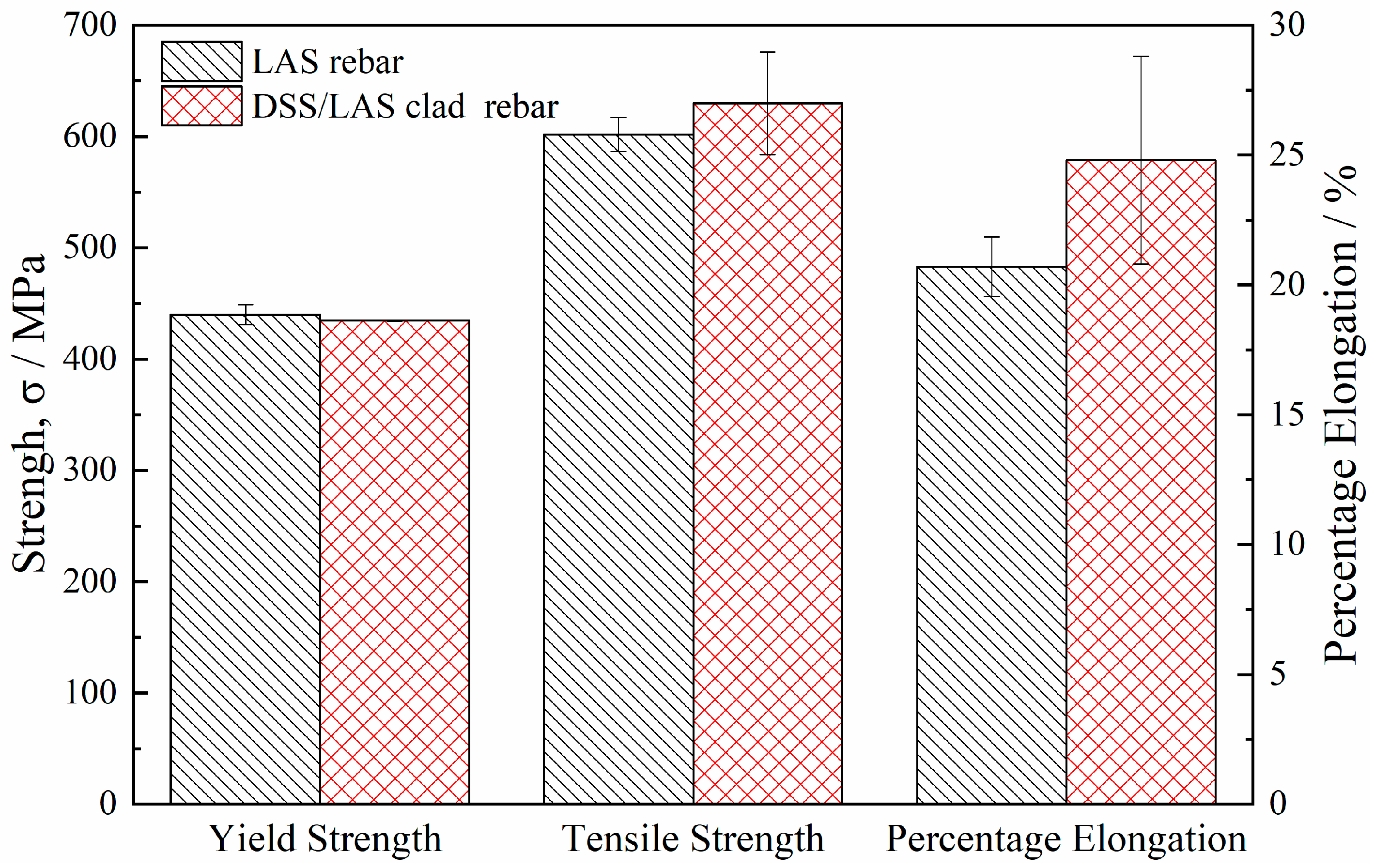
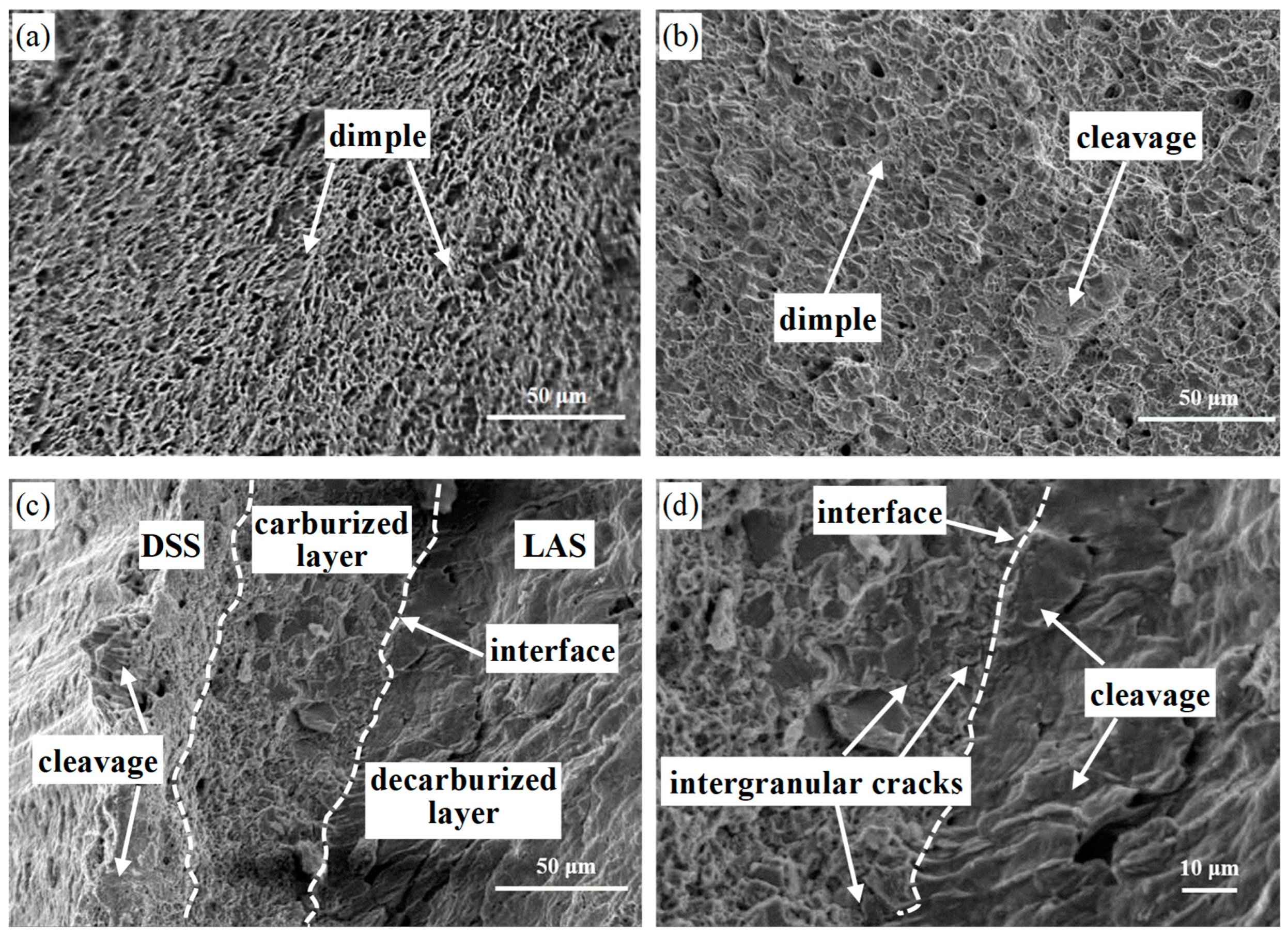
3.2. Effect of DSS Cladding on Tensile Properties

Figure 8 shows the tensile properties of the LAS rebar and the DSS/LAS-clad rebar. The results show that the mechanical properties of the DSS/LAS-clad rebar are better than those of the LAS rebar. Compared with the LAS rebar, the DSS/LAS-clad rebar has 435 MPa of yield strength, slightly below the 440 MPa of the LAS rebar, while the tensile strength increases from 600 MPa to 630 MPa and the percentage elongation slightly increases from 20.7% to 24.8%. In other words, DSS cladding is beneficial for improving the mechanical properties of the LAS rebar. Khodadad et al. [23] evaluated the effects of the thickness of the cladding on the stress–strain curves by defining relative thickness: β = d (clad)/d (substrate). Similarly, Dhib et al. [24] obtained the result that the stress–strain curve of a bi-material-clad plate is between the tensile curves of the pure clad layer and the pure substrate metal when β = 1. In our study, although the thickness of the DSS cladding is far less than that of the LAS, the tensile properties of the DSS/LAS-clad rebar were also found to be between the tensile properties of the LAS and DSS. The possible reasons for the increase in tensile strength are that (i) the strength and plasticity of the DSS are higher than those of the LAS, and (ii) the channel cracks formed by the growth and propagation of microcracks in the carburized layer are effectively suppressed by the plastic deformation zone of the cladding layer, thereby strengthening the matrix [3]. In addition to the DSS’s high plasticity, the percentage elongation increase depends on the interfacial bonding strength, especially when the LAS core is completely cladded by DSS. Nambu et al. [25] found that the delamination cracks make the deformation of each component layer of metal composites uncoordinated, so the whole plastic deformation ability decreases during the tensile process.
Fractography observations were undertaken for the fracture surface of the DSS/LAS-clad rebar to study the fracture behavior of the DSS cladding and the LAS core. The fracture morphology of the DSS/LAS-clad rebar is shown in Figure 9. Figure 9a shows the typical characteristic features of ductile fractures in the DSS cladding, which include a large number of refined dimples. Compared with the DSS cladding, the LAS core fractures in mixed mode with ductile and cleavage features, as shown in Figure 9b. It is clear that ferrite with many coarse dimples surrounds pearlites with cleavage planes. The fracture morphology at the interface shows laminated gradient distribution characteristics, as presented in Figure 9c,d, including ductile fractures of the DSS cladding, intergranular fractures of the carburized layer, and cleavage fractures of the decarburized layer. The cleavage feature can be attributed to the ferrite phase, which is particularly susceptible to brittle fractures following a transgranular path along the (1 0 0) planes [26]. It is noteworthy that a few cleavage planes exist in the DSS cladding near the carburized layer; their presence is related to the propagation of intergranular cracks in the carburized layer and to the ferrite that exists in the DSS cladding. Wang et al. [11] indicated that thick intergranular tunnel cracks seriously affect the tensile properties of clad plates, while thin intergranular tunnel cracks cannot worsen tensile ductility. Figure 9c shows that, in our study, intergranular fractures exist only in the carburized layer, which indicates that DSS cladding can effectively prevent the propagation of cracks in the early stages. With the increase in stress, thick intergranular cracks converged by thin intergranular cracks pass through the DSS cladding near the carburized layer, resulting in local cleavage fractures. The LAS core and DSS cladding are always a whole from the beginning of the tensile load to the fracture, due to the strong interface bonding. According to Yanagimoto et al., the elongation of the brittle layer and the ductile layer should be identical if the multilayer sheet is subjected to pure tensile deformation [26]. In this work, pure LAS and pure DSS have different elongations. However, a pair of external stresses on the LAS and DSS suppress premature necking, thus achieving a consistent elongation [26,27]. In other words, the elongation of the LAS core and the DSS cladding is the same when the DSS/LAS-clad rebar is subjected to the tensile load. With the increase in load, the necking is initiated in the LAS core first. If the bonding strength between the core and cladding is sufficient, the cladding will restrain the reduction in the section area of the LAS core, and enhance the mechanical properties of the clad rebar. Based on the iso-strain conditions in the metal-laminated structural composites, the Voigt model [28] proposed the expressions of modulus E and yield strength σ:
E = Eafa + Ebfb
σ = σafa + σbfb
where fa and fb are the volume fraction of the two components, respectively; Ea and Eb are the moduli of the two components; and σa and σb are the yield strengths of the two components.
Compared with the LAS rebar, however, the change in yield strength of the DSS/LAS rebar is not significant, and the elongation increases slightly, as shown in Figure 8. The main reason for this is that, as mentioned above, the thickness of the DSS cladding is far less than that of the LAS core, indicating that the main contribution of mechanical properties comes from the LAS core itself.

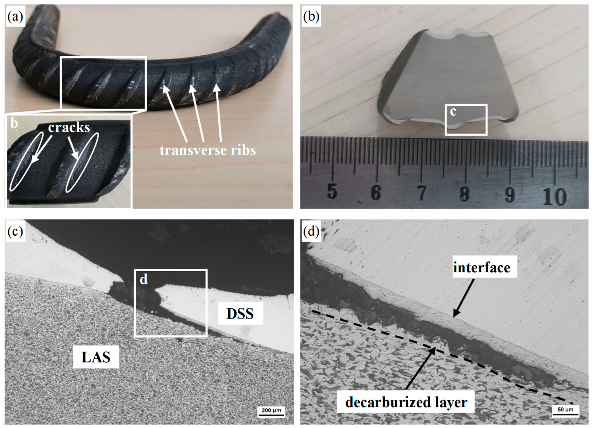
3.3. Effect of Cladding Thickness on Bending Properties

Some DSS/LAS-clad rebars crack at the root of the transverse rib after bending, as presented in Figure 10a. Interestingly, these cracks are located on the same side of the transverse rib’s root, where the DSS’s thickness cladding is at its thinnest. In addition, there are no obvious cracks on the bending compressive stress side compared with the bending tensile stress side, as shown in Figure 10b. That is to say, the thickness of the cladding and the bending tensile stress are the main causes of cracking. In particular, a thinner cladding may cause exposure of the LAS core, which not only results in bending and cracking but also seriously affects the corrosion resistance of materials. Figure 10c reveals that obvious necking is located on the cladding surface, and a brittle fracture occurs in the middle of the cladding. In addition, the crack propagates to the left and right as the bending degree increases. As shown in Figure 7b, although the thickness of the interfacial martensite layer decreases after rolling, it does not disappear completely. It is equivalent to increasing the amount of martensite per unit of cladding thickness when the cladding thickness is reduced. Therefore, in the bending process, martensite cracking leads to the propagation of cracks on the surface and in the center. When the crack propagates to the interface, it is hindered by the interface with higher bonding strength, so it turns to the decarburized layer with lower strength and continues to propagate, which is consistent with the crack propagation seen along the decarburized layer in Figure 10d.
In order to further study the reduction in cladding thickness, the finite element method (FEM) was performed using ABAQUS software. The rollers are set as rigid bodies and the workpiece is set as a deformable body. The element type is C3D8RT, with a total of 369,840 elements, of which the cladding element size is 0.39 mm. The dense mesh setting is useful for accurately studying the deformation behavior of the cladding. It is worth noting that a common node mesh is used during the simulation to avoid the relative sliding of the LAS core and DSS cladding. Figure 11a shows the interface in the DSS/LAS-clad rear section. There are obvious differences in the thickness of the cladding on both sides of the transverse rib root, as shown in marks A and B in Figure 11a. Figure 11b,c show the results of the FEM simulation in the last rolling pass. The transverse rib root has a larger equivalent plastic strain value (marked in green) during rolling, as presented in Figure 11b, which shows that the transverse rib root undergoes severe plastic deformation compared with other parts of the DSS/LAS-clad rebar. Figure 11c shows that the workpiece presents a much larger deformation on the side of the inverse rolling direction (IRD, marked D) than on the side of the rolling direction (RD, marked C). Specifically, the equivalent plastic strain on the IRD is ~2.0, while the equivalent plastic strain on the RD is only ~0.34. In addition, it is also can be seen that the groove is not completely filled with the workpiece, which means that an interspace appears between the workpiece and the groove. After the workpiece enters the groove, the forming of the transverse rib undergoes the following stages: (i) the metal restricted by the groove flows freely in the transverse direction after the workpiece comes into contact with the front end of the groove (marked C in Figure 11c); (ii) the metal is restricted by the back end of the groove (marked D in Figure 11c), and then flows towards the side wall of the groove (red arrow). Therefore, there is a thin cladding with larger plastic deformation at the root of the transverse rib because the deformation of the DSS is significantly larger than that of the LAS. The result of the numerical simulation shown in Figure 11d agrees with the actual results. In order to determine how to effectively suppress the cladding thickness reduction and completely eliminate the interfacial martensite after rolling, it is necessary to further study the groove design and rolling temperature.

4. Conclusions

The interfacial characteristics and mechanical properties of the DSS/LAS-clad rebar were investigated in this study. The main conclusions of this research are as follows:
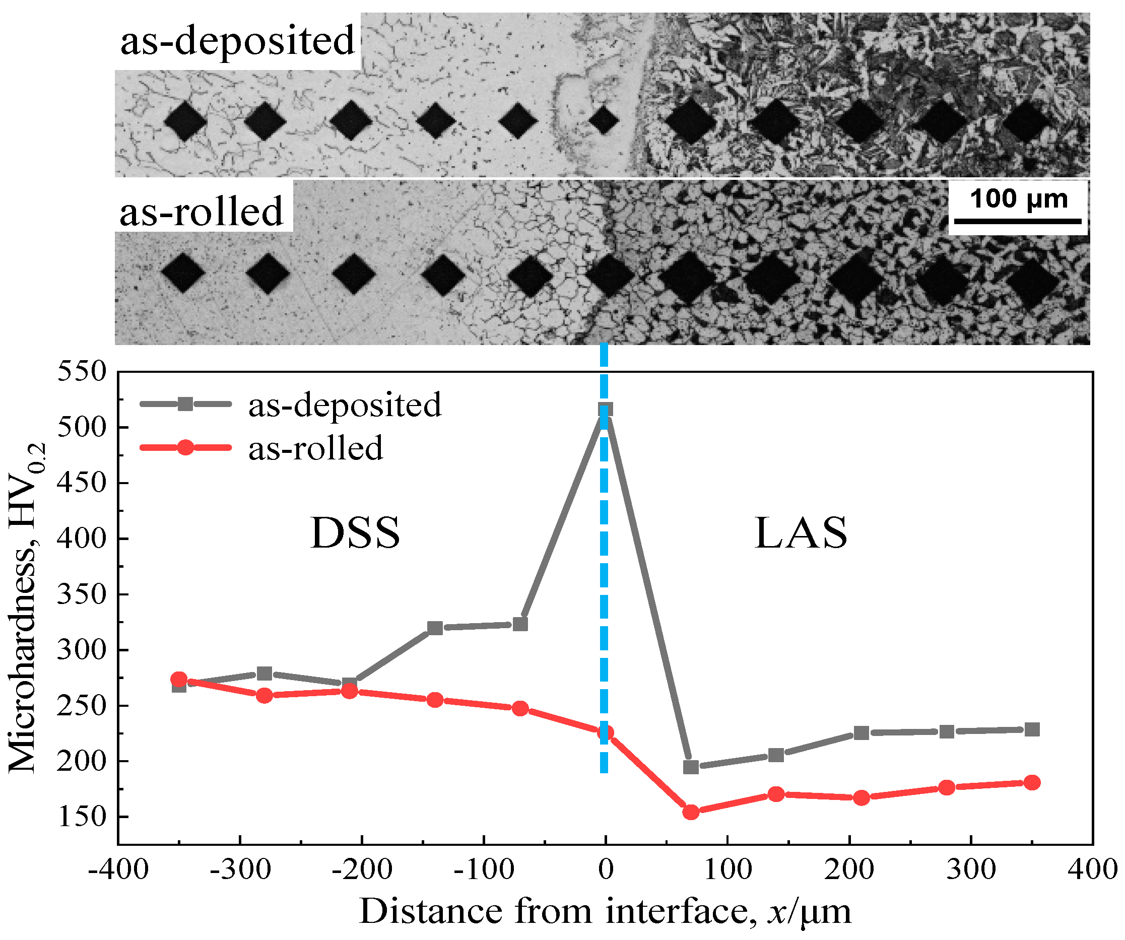
  • Due to the effects of element diffusion and rolling reduction, the decarburization layer and the carburized layer form on the LAS side and the DSS side, respectively, and the thickness of the martensite layer at the interface decreases gradually. The microhardness at the interface reduces from 516.4 HV0.2 in the as-deposited material to 225.6 HV0.2 in the rolled material.
  • Compared with the LAS rebar, the DSS/LAS-clad rebar has good mechanical properties, including 435 MPa of yield strength, 630 MPa of tensile strength and a 24.8% percentage elongation, which benefits from the dispersion strengthening that exists in the LAS side and the inhibition of premature necking by the DSS cladding.
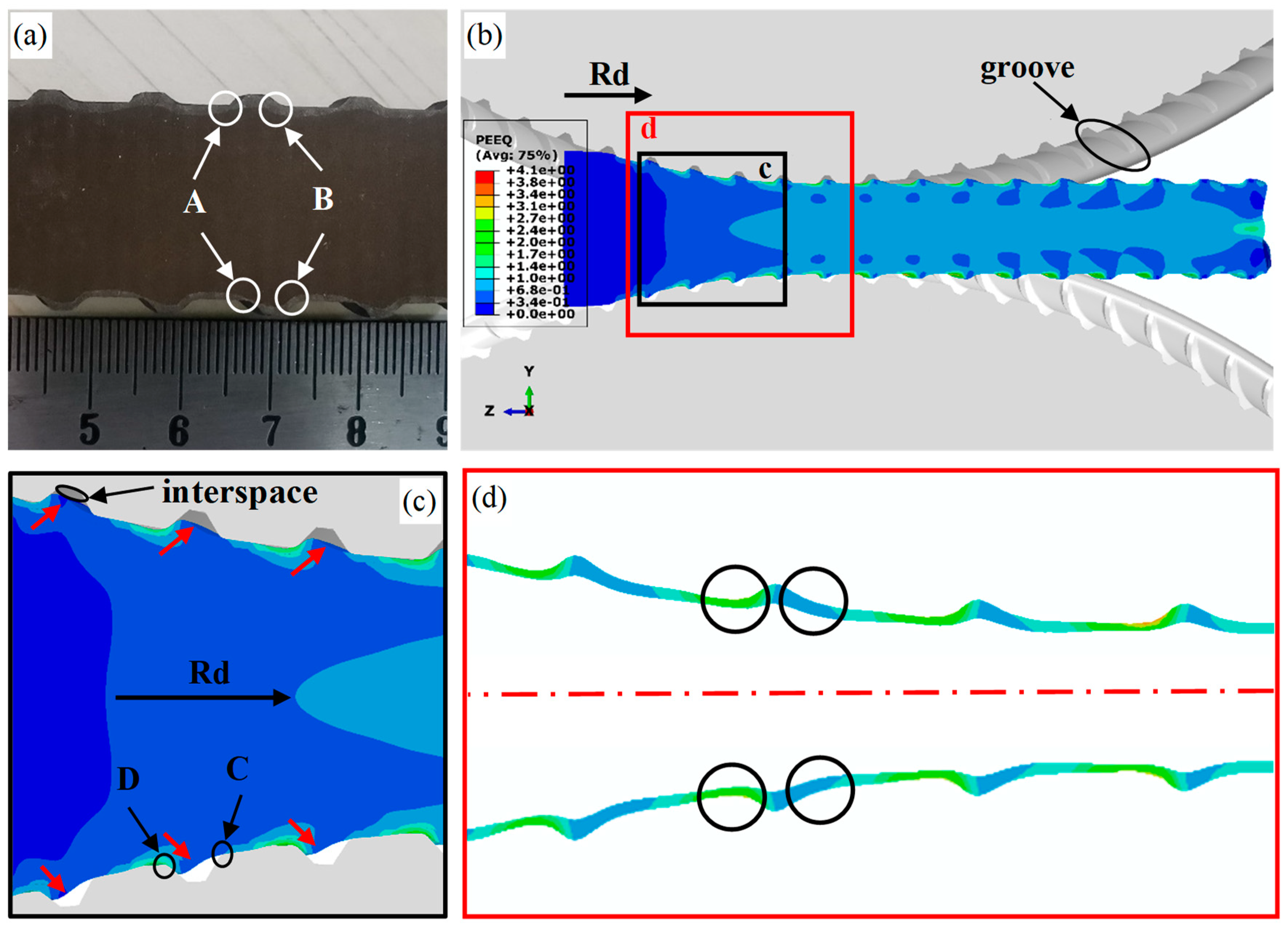
  • The shape of the groove causes a reduction in the cladding thickness at the transverse rib root of the DSS/LAS-clad rebar during the rolling process. The thinning of the cladding and the brittleness of the martensite layer leads to the cracking of the rebar’s transverse rib root. In particular, if the LAS at the transverse rib root is exposed due to a lack of DSS cladding, the decarburized layer with low strength will directly cause the root to crack after bending.

Author Contributions

Conceptualization, G.F., X.L. (Xuming Liu) and J.M.; methodology, J.M.; software, X.L. (Xuming Liu); formal analysis, J.M., X.L. (Xuming Liu.) and J.C.; investigation, J.M. and X.L. (Xuming Liu); resources, G.F.; data curation, X.L. (Xin Liu); writing—original draft preparation, J.M.; writing—review and editing, B.W.; supervision, G.F.; project administration, G.F. and H.Z. All authors have read and agreed to the published version of the manuscript.

Funding

This research received no external funding.

Conflicts of Interest

The authors declare no conflict of interest.

References

  1. Yazdani, M.; Toroghinejad, M.R.; Hashemi, S.M. Investigation of Microstructure and Mechanical Properties of St37 Steel-Ck60 Steel Joints by Explosive Cladding. J. Mater. Eng. Perform. 2015, 24, 4032–4043. [Google Scholar] [CrossRef]
  2. Cao, R.; Zhao, X.K.; Ding, Y.; Zhang, X.B.; Jiang, X.X.; Yan, Y.J.; Chen, J.H. Effects of the rolling temperature on microstructure and mechanical properties of 2Cr13/316L laminated composites prepared by accumulative roll-bonding (ARB). Mater. Charact. 2018, 139, 153–164. [Google Scholar] [CrossRef]
  3. Liu, B.X.; Yin, F.X.; Dai, X.L.; He, J.N.; Fang, W.; Chen, C.X.; Dong, Y.C. The tensile behaviors and fracture characteristics of stainless steel clad plates with different interfacial status. Mater. Sci. Eng. A 2017, 679, 172–182. [Google Scholar] [CrossRef]
  4. Kaçar, R.; Acarer, M. Microstructure–property relationship in explosively welded duplex stainless steel–steel. Mater. Sci. Eng. A 2003, 363, 290–296. [Google Scholar] [CrossRef]
  5. Lee, K.S.; Jun, H.J.; Lee, Y.S. Fabrication of bimetallic rods consist of a Zr-based bulk metallic glass and a crystalline copper by co-extrusion. Intermetallics 2010, 18, 1958–1963. [Google Scholar] [CrossRef]
  6. Chen, G.; Li, J.T.; Yu, H.L.; Su, L.H.; Xu, G.M.; Pan, J.S.; You, T.; Zhang, G.; Sun, K.M.; He, L.Z. Investigation on bonding strength of steel/aluminum clad sheet processed by horizontal twin-roll casting, annealing and cold rolling. Mater. Des. 2016, 112, 263–274. [Google Scholar] [CrossRef]
  7. Zhao, Z.; Tariq, N.u.H.; Tang, J.; Jia, C.; Qiu, X.; Ren, Y.; Liu, H.; Shen, Y.; Du, H.; Cui, X.; et al. Microstructural evolutions and mechanical characteristics of Ti/steel clad plates fabricated through cold spray additive manufacturing followed by hot-rolling and annealing. Mater. Des. 2020, 185, 108249. [Google Scholar] [CrossRef]
  8. Bina, M.H.; Dehghani, F.; Salimi, M. Effect of heat treatment on bonding interface in explosive welded copper/stainless steel. Mater. Des. 2013, 45, 504–509. [Google Scholar] [CrossRef]
  9. Du, J.J.; Zhang, X.; Liu, B.X.; Dong, Y.C.; Feng, J.H.; Chen, C.X.; Yin, F.X. Interface strengthening and fracture behavior of multilayer TWIP/TRIP steel. Mater. Chem. Phys. 2019, 223, 114–121. [Google Scholar] [CrossRef]
  10. Liu, B.X.; Wang, S.; Fang, W.; Ma, J.L.; Yin, F.X.; He, J.N.; Feng, J.H.; Chen, C.X. Microstructure and mechanical properties of hot rolled stainless steel clad plate by heat treatment. Mater. Chem. Phys. 2018, 216, 460–467. [Google Scholar] [CrossRef]
  11. Wang, S.; Liu, B.X.; Chen, C.X.; Feng, J.H.; Yin, F.X. Microstructure, mechanical properties and interface bonding mechanism of hot-rolled stainless steel clad plates at different rolling reduction ratios. J. Alloys Compd. 2018, 766, 517–526. [Google Scholar] [CrossRef]
  12. Zhu, Z.; He, Y.; Zhang, X.; Liu, H.; Li, X. Effect of interface oxides on shear properties of hot-rolled stainless steel clad plate. Mater. Sci. Eng. A 2016, 669, 344–349. [Google Scholar] [CrossRef]
  13. Liu, B.X.; Wang, S.; Fang, W.; Yin, F.X.; Chen, C.X. Meso and microscale clad interface characteristics of hot-rolled stainless steel clad plate. Mater. Charact. 2019, 148, 17–25. [Google Scholar] [CrossRef]
  14. Xie, G.M.; Luo, Z.A.; Wang, G.L.; Li, L.; Wang, G.D. Interface Characteristic and Properties of Stainless Steel/HSLA Steel Clad Plate by Vacuum Rolling Cladding. Mater. Trans. 2011, 52, 1709–1712. [Google Scholar] [CrossRef]
  15. Gutiérrez, I.; Urcola, J.J.; Bilbao, J.M.; Villar, L.M. Bonding by hot extrusion of Incoloy 825 and Duplex 2205 to low alloy steel. Mater. Sci. Technol. 1991, 7, 761–769. [Google Scholar] [CrossRef]
  16. Ma, H.; Qin, G.; Geng, P.; Li, F.; Fu, B.; Meng, X. Microstructure characterization and properties of carbon steel to stainless steel dissimilar metal joint made by friction welding. Mater. Des. 2015, 86, 587–597. [Google Scholar] [CrossRef]
  17. Chen, C.X.; Liu, M.Y.; Liu, B.X.; Yin, F.X.; Dong, Y.C.; Zhang, X.; Zhang, F.Y.; Zhang, Y.G. Tensile shear sample design and interfacial shear strength of stainless steel clad plate. Fusion Eng. Des. 2017, 125, 431–441. [Google Scholar] [CrossRef]
  18. Yan, M.; Sun, J.-N.; Huang, H.-G.; Chen, L.; Dong, K.; Chen, Z.-Y. Effect of hot rolling and cooling process on microstructure and properties of 2205/Q235 clad plate. J. Iron Steel Res. Int. 2018, 25, 1113–1122. [Google Scholar] [CrossRef]
  19. Mas, F.; Tassin, C.; Valle, N.; Robaut, F.; Charlot, F.; Yescas, M.; Roch, F.; Todeschini, P.; Bréchet, Y. Metallurgical characterization of coupled carbon diffusion and precipitation in dissimilar steel welds. J. Mater. Sci. 2016, 51, 4864–4879. [Google Scholar] [CrossRef]
  20. Li, Z.; Zhao, J.; Jia, F.; Liang, X.; Zhang, Q.; Yuan, X.; Jiao, S.; Jiang, Z. Interfacial characteristics and mechanical properties of duplex stainless steel bimetal composite by heat treatment. Mater. Sci. Eng. A 2020, 787, 139513. [Google Scholar] [CrossRef]
  21. Tao, Y.; Yu-an, J.; Xiaolin, Y.; Wenbin, L.; Qihang, P.; Guo, J. Microstructures and properties of roll-bonded stainless/medium carbon steel clad plates. J. Mater. Process. Technol. 2019, 266, 264–273. [Google Scholar] [CrossRef]
  22. Xiao, F.; Wang, D.; Hu, W.; Cui, L.; Gao, Z.; Zhou, L. Effect of Interlayers on Microstructure and Properties of 2205/Q235B Duplex Stainless Steel Clad Plate. Acta Metall. Sin-Engl. 2020, 33, 679–692. [Google Scholar] [CrossRef]
  23. Motarjemi, A.K.; Koçak, M.; Ventzke, V. Mechanical and fracture characterization of a bi-material steel plate. Int. J. Press. Vessel. Pip. 2002, 79, 181–191. [Google Scholar] [CrossRef]
  24. Dhib, Z.; Guermazi, N.; Ktari, A.; Gasperini, M.; Haddar, N. Mechanical bonding properties and interfacial morphologies of austenitic stainless steel clad plates. Mater. Sci. Eng. A 2017, 696, 374–386. [Google Scholar] [CrossRef]
  25. Nambu, S.; Michiuchi, M.; Inoue, J.; Koseki, T. Effect of interfacial bonding strength on tensile ductility of multilayered steel composites. Compos. Sci. Technol. 2009, 69, 1936–1941. [Google Scholar] [CrossRef]
  26. Yanagimoto, J.; Oya, T.; Kawanishi, S.; Tiesler, N.; Koseki, T. Enhancement of bending formability of brittle sheet metal in multilayer metallic sheets. CIRP Ann. 2010, 59, 287–290. [Google Scholar] [CrossRef]
  27. Liu, B.X.; Huang, L.J.; Geng, L.; Wang, B.; Cui, X.P. Fracture behaviors and microstructural failure mechanisms of laminated Ti–TiBw/Ti composites. Mater. Sci. Eng. A 2014, 611, 290–297. [Google Scholar] [CrossRef]
  28. Saha, S.; Chattopadhyay, A.; Singh, A.K. Propagation of rayleigh type wave in an initially stressed voigt type viscoelastic layer. Procedia Eng. 2017, 173, 1162–1168. [Google Scholar] [CrossRef]
Figure 1. Simplified diagrams of the DSS/LAS-clad rebar production process. (a) The manufacturing of the DSS/LAS billet, which used metal deposition, (b) the DSS/LAS billet soaking in a furnace, (c) hot rolling, (d) macro-scale external and cross-sectional views.
Metals 12 01573 g001
Figure 2. Microstructure of the DSS/LAS-clad rebar before and after rolling: (a,c) DSS/LAS billet as deposited, (b,d) rolled DSS/LAS clad rebar.
Metals 12 01573 g002
Figure 3. SEM images and EDS analysis of samples: (a) EDS results of points 1 and 2 in as-deposited materials, (b) EDS results of points 3 and 4 in rolled materials.
Metals 12 01573 g003aMetals 12 01573 g003b
Figure 4. SEM image and EDS analysis of the selected area in the rolled material.
Metals 12 01573 g004
Figure 5. EDS linear scan analysis across the interface: (a) as-deposited, (b) as-rolled.
Metals 12 01573 g005
Figure 6. Variation in hardness across the interface of the fabricated samples.
Metals 12 01573 g006
Figure 7. SEM image and Schaeffler diagram: (a) as deposited, (b) as rolled, (c) Schaeffler diagram relating to the equivalents of Cr and Ni.
Metals 12 01573 g007
Figure 8. Tensile properties of the LAS rebar and the DSS/LAS-clad rebar.
Metals 12 01573 g008
Figure 9. Fracture morphology of the DSS/LAS-clad rebar: (a) DSS cladding, (b) LAS core, (c,d) interface zone.
Metals 12 01573 g009
Figure 10. Results of the bending test of the DSS/LAS-clad rebar: (a) DSS/LAS-clad rebar after bending, (b) longitudinal section of the DSS/LAS-clad rebar after bending, (c,d) metallographic diagram of the crack.
Metals 12 01573 g010
Figure 11. DSS/LAS-clad rebar and FEM simulation: (a) longitudinal section of the DSS/LAS-clad rear, (b) result of the FEM simulation based on ABAQUS, (c) deformation of transverse ribs, (d) variation in DSS cladding thickness.
Metals 12 01573 g011
Table 1. The chemical composition of the constituent materials (mass%).
CSiMnPSNCrNiMoFe
LAS0.2460.4961.240.0110.027-0.200.07-Bal.
DSS0.0260.4051.220.0220.0010.16623.14.843.28Bal.
Publisher’s Note: MDPI stays neutral with regard to jurisdictional claims in published maps and institutional affiliations.

