Article

Microstructure and Mechanical Properties of Ultrafine Quaternary Al-Cu-Si-Mg Eutectic Alloy

1
Brunel Centre for Advanced Solidification Technology (BCAST), Brunel University London, London UB8 3PH, UK
2
National Physical Laboratory (NPL), London TW11 0LW, UK
*
Author to whom correspondence should be addressed.
Metals 2022, 12(1), 7; https://doi.org/10.3390/met12010007
Submission received: 27 November 2021 / Revised: 16 December 2021 / Accepted: 16 December 2021 / Published: 21 December 2021

Abstract

:
The microstructure evolution and mechanical properties of quaternary Al-Cu-Si-Mg eutectic alloy prepared via arc melting and suction casting were studied. This alloy exhibits a single endothermic DSC peak with a melting temperature of 509 °C upon heating, suggesting a eutectic reaction. The cast alloy microstructure consisted of four phases, α-Al, Al2Cu ( θ ), Si and Al4Cu2Mg8Si7 (Q), in the eutectic cells and also in the nano-scale anomalous eutectic in the intercellular regions. The eutectic cells show different morphologies in different parts of the sample. Well-defined orientation relationships between the α-Al, Al2Cu, and Q phases were found in the eutectic cell centres, while decoupled growth of Q phase occurred at the cell boundaries. The bimodal microstructure exhibits excellent compressive mechanical properties, including a yield strength of 835 ± 35 MPa, a fracture strength of ~1 GPa and a compressive fracture strain of 4.7 ± 1.1%. The high strength is attributed to a combination of a refined eutectic structure and strengthening from multiple hard phases.

1. Introduction

Eutectic alloys have been extensively studied for decades, due to their low melting temperature, high strength and good castability [1,2,3,4]. Eutectic solidification takes place by nucleation and growth processes, which affect the final microstructure and properties [5,6]. There are many investigations into binary eutectic alloys, and several theories have been established. For example, it is found that λ 2 ν and λ Δ T are constant in binary lamellar and rod eutectic alloys solidified at small undercoolings, where λ , ν and Δ T are the eutectic interlamellar or inter-rod spacing, the solidification growth rate and the solid/liquid interface temperature during solidification, respectively [7,8,9]. Eutectic solidification at large undercooling, i.e., rapid solidification, has also been investigated. A refined nano-scale eutectic structure is usually found in rapidly solidified binary eutectic alloys, and there is a critical value of growth rate leading to the decoupling of eutectic growth [10,11]. This leads to a transition from coupled lamellar to anomalous eutectic structure after rapid solidification, with the onset of non-cooperative growth often associated with a kinetic shift in the eutectic composition [12,13,14,15].
The addition of minor ternary element additions to binary eutectic alloys is often able to modify the eutectic microstructure [16,17,18,19], leading to effects such as: (1) binary eutectic cellular growth, (2) binary eutectic non-coupled growth, or (3) the formation of a ternary eutectic structure with three different coupled or non-coupled phases [20,21,22,23,24,25]. Eutectic solidification in undercooled melts is governed by the diffusion of elements in front of the solid/liquid interface, and the first two effects of adding a ternary element are caused by an increase in constitutional undercooling at the solid/liquid interface and a corresponding destabilisation of the solid/liquid interface [17,18,26]. Alternatively, the addition of a ternary element may be sufficient to reach a ternary eutectic composition with three distinct eutectic phases, and more complex coupled or non-coupled three-phase eutectic patterns form [27,28,29].
Although many investigations have been done on binary and, to a lesser extent, ternary eutectic alloys, there has been very little investigation of quaternary eutectic alloys with four distinct eutectic phases [29]. Eutectic solidification is the basis of many cast alloys, and it is worth studying quaternary eutectic or multi-component eutectic alloys, since with more elements the alloys can form more complex microstructures and may be able to achieve higher strengths [29,30,31]. This paper describes an investigation into the solidification behaviour of a quaternary Al-Cu-Si-Mg eutectic alloy when manufactured by rapid solidification. In addition, the compressive mechanical properties of the alloy were studied.

2. Materials and Methods

A 1 kg starting alloy ingot with a nominal quaternary eutectic composition of Al-28 wt%Cu-6wt%Si-2.2wt%Mg [32] was prepared by melting appropriate amounts of Al (99.94%), Al-50wt%Si (99.72%), Cu (99.99%) and Mg (99.92%) in an induction furnace. The resulting composition of the ingot was Al-27 ± 0.25wt%Cu-5.5 ± 0.13wt%Si-2.3 ± 0.11wt%Mg-0.1 ± 0.06wt%Fe, as measured by inductively-coupled plasma mass spectrometry (ICP-MS)(Thermo Fisher Scientific, Waltham, MA, USA). The ingot was then processed into 3 mm diameter × 30 mm long rods by arc-melting under an argon atmosphere followed by suction casting into a water-cooled copper mould maintained at a temperature of 16 °C, using an Edmund Buhler MAM-1 system (Edmund Bühler GmbH, Bodelshausen, Germany). Specimens for microstructural examination were taken from the half-length and bottom of the rods, as shown in Figure 1. After cold mounting, grinding and polishing, they were etched for 5 s in a 0.5 vol% solution of HF acid. Microstructural characterisation was performed using a combination of scanning electron microscopy (SEM)(Carl Zeiss, Oberkochen, Germany) in a Zeiss Supra 35 operated in backscattered electron imaging mode with an accelerating voltage of 20 kV. A Bruker D8 Advance X-ray diffractometer (XRD)(BRUKER, Billerica, Massachusetts, USA) with Cu X-ray source and Ni filter operating at a voltage of 40 kV, a current of 40 mA, and a step size of 0.24 degrees/min was used for phase identification. Specimens for SEM characterisation with very high magnification, transmission electron microscopy (TEM) and transmission Kikuchi diffraction (TKD) were prepared using focused ion beam (FIB)(Carl Zeiss, Oberkochen, Germany) milling with an Mo grid and Pt deposition in a Zeiss Auriga Cross Beam instrument. Specimens were thinned to a thickness of about 80–150 nm. A JEOL 2100F TEM (JEOL, Tokyo, Japan) was used to study the as-cast eutectic microstructure. The video obtained from FIB-SEM tomography slices shows the 3D morphology of the eutectic (Video S1). TKD maps were acquired in a Zeiss Auriga-60 SEM (Carl Zeiss, Oberkochen, Germany) using 20 kV electrons and a 60 µm diameter objective aperture with ‘High Current’ mode switched on. The sample working distance was 3.1 mm and the sample was back-tilted to −30°. TKD maps were captured using an Oxford Instruments Nordlys F camera and Aztec software using a 70 ms pattern exposure time and 20 nm map step size. The melting temperature and heat of fusion of the quaternary alloy were measured using a Netzsch 404F1 differential scanning calorimetry (DSC)(NETZSCH Group, Selb, Germany) instrument operated at a heating rate of 20 K/min, in a dynamic flow of Ar at a flow rate of 50 mL/min. Cylindrical specimens sectioned from the half-length of the 30 mm rod with a 2:1 aspect ratio were prepared for compression testing, as shown in Figure 1. Uniaxial compression (Instron, Norwood, MA, USA) tests were carried out on three separate samples at room temperature with an initial strain rate of 10−3 s−1.

3. Results

3.1. Microstructure

Figure 2a shows the XRD spectrum obtained from the as-cast sample. The quaternary eutectic alloy consisted of four crystalline phases, which corresponded to α-Al, Si, Al2Cu and Al4Cu2Mg8Si7 (Q). This XRD result agreed with the phases observed previously in the quaternary Al-Cu-Si-Mg eutectic alloy processed by directional solidification [33]. Figure 2b shows a DSC trace from the quaternary alloy obtained during heating at 20 K/min. Only one endothermic DSC peak with a shoulder was observed, and the onset and peak temperature were found to be 509 °C and 553 °C, respectively. This indicates that the melting of the four phases takes place at the close temperature, corresponding to quaternary eutectic reaction:
L α - Al + Si + θ - Al 2 Cu + Q
The melting temperature is close to the expected melting temperature (507 °C) of the quaternary Al-Cu-Si-Mg eutectic on the equilibrium phase diagram [32].
Figure 3a,b shows the microstructures of the quaternary Al-Cu-Si-Mg alloy, taken from transverse and longitudinal sections at the half-length position in the sample, respectively. The microstructures of the transverse and longitudinal sections are quite similar, indicating a 3D equiaxed cellular structure, consisting of coupled eutectic cells, 5–25 μm in size, and anomalous eutectic in the intercellular regions. The microstructures of the alloy obtained from the transverse and longitudinal section at the bottom of the sample are shown in Figure 3c,d, respectively. The microstructures of the transverse and longitudinal sections are again quite similar, again indicating a 3D equiaxed cellular structure, consisting of coupled eutectic cells, 10–25 μm in size, and anomalous eutectic in the intercellular regions. The main differences between the microstructures at the half-length in Figure 3a,b and at the bottom in Figure 3c,d are that (1) the spacing of the eutectic phases is much smaller at the bottom, indicating a faster cooling rate and solidification speed, and (2) the size of the eutectic cells is a little larger at the bottom. Schematics of the microstructures at the half-length and the bottom are shown in Figure 3e,f, respectively.
Figure 4a shows the microstructure at higher magnification, showing both the coupled cellular eutectic structure and the intercellular regions, taken from a transverse section of the half-length sample. The coupled eutectic cells and the anomalous eutectic in the intercellular regions can be seen more clearly. The interlamellar spacing of the Al2Cu and α-Al phases at the cell boundaries is 500–800 nm, and at the cell centre is 150–250 nm. SEM EDX point analyses of Spot 1 and Spot 2 taken from Figure 4a are displayed in Figure 4b,c. All four elements were present in both the cell centres and the intercellular regions, but there was considerably more Si and Mg in the anomalous eutectic intercellular regions.
Figure 5a again shows the microstructure at higher magnification, again showing the coupled cellular eutectic structure and the intercellular regions, but this time taken from a transverse section of the bottom sample. There were some branchings of the eutectic phases at the cell boundaries with an interlamellar spacing (Al2Cu and α-Al) of 70–160 nm. However, in the cell centre, an anomalous eutectic structure with a coarse morphology was observed. The corresponding SEM-EDX mapping is shown in Figure 5b, which was taken from Area 1 in Figure 5a. Si was again shown to be segregated into the intercellular regions. Such elemental distribution was also observed in the longitudinal section of the half-length and bottom region of the sample.
Figure 6a shows TEM bright-field images of the microstructure taken from the cell centres at the half-length position of the rod. In the cell centres, there are mainly three phases (α-Al, Al2Cu and Q). The Q phase is in the form of particles with a diameter of 50–100 nm, attached to the Al2Cu lamellae. Although a small fraction of Si phase particles can also sometimes be observed in the cell centres, more often only three phases (α-Al, Al2Cu and Q) co-exist. Figure 6b shows selected area diffraction patterns (SADPs) from α-Al, Si, Q and Al2Cu, corresponding to [1 0 0]Al, [0 0 1]Si, [0 0 0 1]Q and [1 1 0]Al2Cu zone axes, respectively. From TEM diffraction patterns (not shown here), there are no well-defined orientation relationships between Si and the Al2Cu, Q and α-Al phases. However, well-defined orientation relationships between the Q, Al2Cu and α-Al phases were found, and further characterisation with SEM-TKD are shown in Figure 7 and Figure 8.
Figure 7a shows typical eutectic colonies at the half-length position in the rod, taken from the sample prepared by FIB. The identified phases from TKD include the Al2Cu, α-Al and Q phases, in agreement with the TEM results shown in Figure 6. In TKD, the detected diffraction pattern comes from the bottom face of the sample, and the SEM image in Figure 7a is also from the bottom face. Figure 7b shows the distribution of the eutectic phases α-Al, Al2Cu and Q, with the Q and Al2Cu phases at the cell boundaries showing a much coarser morphology. Although Si particles were visible in the SEM image of Figure 7 and could be identified as diamond cubic phase in the TEM, they could not be discriminated from the fcc α-Al phase using TKD, because of the similar crystal structures and backscatter coefficients between Si and α-Al, so that their TKD patterns are expected to be nearly identical. The bottom right corner of the SEM image of Figure 7a shows a mixture of Si and Al phases, but this region is indexed as a single α-Al grain in Figure 7b,c. There are two possible explanations: either the detected diffraction pattern is a mixture of Si and α-Al phases with a cube–cube orientation relationship and therefore similar diffraction patterns, or one of the phases dominates the detected signal. The inverse pole figure (IPF) of the selected region in Figure 7a is displayed in Figure 7c. The α-Al and Al2Cu plates have an interlamellar spacing of ~150 nm and a good orientation relationship from the centre to the edge of the cell. However, the Q phase shows different colours in the IPF map from the centre to the edge of the cell, indicating that misorientations develop during growth. The detailed analysis of the orientation relationship of the three phases (α-Al, Q and Al2Cu) in the centre region has been reported in our previous work [34]. The common directions of Al2Cu, α-Al and Q phases were found to be [120]Al2Cu, [110]Al and [0001]Q, and the common planes were found to be (121) Al2Cu, (111) Al and (31 4 ¯ 0)Q.
An IPF-Z map taken from the cell boundary from the half-length of the sample is shown in Figure 8b, which was taken from the same sample prepared by FIB (Figure 7a). The size of the Q phase particles increased to ~200 nm in the cell boundary. The lamellar α-Al and Al2Cu structure appeared irregular compared with the cell centre. Pole figures of the Al2Cu, α-Al and Q phases in the cell boundary are shown in Figure 8b. The common planes of the α-Al and Al2Cu phases were found to be the same as those in the cell centre without misorientation. However, the Q phase has a large deviation from {0001} and {31 4 ¯ 0} planes, indicating that the Q particles at the cell boundary exhibit different orientations. In other words, there were no well-defined orientation relationships between Q and Al2Cu, or Q and α-Al phases in the cell boundaries.
The detailed microstructure in the bottom part of the rod is shown in Supplementary Material (Video S1). The anomalous eutectic and eutectic branches are shown in Video S1, and it is clearly seen that there are four phases inside the eutectic branches. Many nano-scale Si particles were observed at cell boundaries, and some coarse Al2Cu lamellae with a size of ~500 nm were found at the tip of the eutectic branches. The Q phase shows a rod-like morphology. In addition, the divorced growth of Q fibres from Al2Cu and α-Al lamellas is also seen, which is similar to that at the half-length position of the rod.

3.2. Mechanical Properties

Figure 9 shows a typical compressive stress-strain curve from the quaternary alloy at a strain rate of 1 × 10⁻³ s−1. The alloy exhibits excellent compressive properties. The fracture strength, yield strength and compressive fracture strain were found to be 1036 ± 28 MPa, 835 ± 35 MPa and 4.7 ± 1.1%, respectively. An inset in Figure 9 shows the fractured sample after the compression test. It can be seen that the maximum shear plane is inclined to the load direction by approximately 45°.
The fracture surface of the quaternary alloy taken is shown at low magnification in Figure 10a. The shear band direction is indicated by the white arrow. It can be seen that the fracture surface mainly comprises flat and bumpy features, which are marked in Figure 10a as Area A and Area B, respectively. Many wavy cracks can be observed in the fracture surface. The detailed microstructure of Area A and Area B is shown in Figure 10b,c, respectively. From Figure 10b, the flat features consist of smooth areas and dimples. The detailed microstructure of Area B (Figure 10c) contains a few wavy cracks along the boundaries of cellular colonies, indicating that the majority of the cracks are separated by the boundaries of cellular colonies. In addition, the coarse Al2Cu phase was found to fracture at the boundaries of cellular colonies, as shown in Figure 10c. This is because the coarse Al2Cu particles are brittle and therefore vulnerable to crack initiation.
Figure 11a shows TEM bright-field image along [001]Al zone axis of α-Al lamella within one eutectic cellular colony at low magnification. It can be noted from strain contrast that the orientation of α-Al is same from the centre to the boundary of the cell. A large number density of dislocation can be seen either in the eutectic cell or at the intercellular region. The nanoscale anomalous eutectic was found at cell boundaries. Figure 11b shows the dislocations inside the cell. The dislocations were entrapped inside the eutectic phases. No dislocations are found in Q or Al2Cu phase.

4. Discussion

4.1. Microstructure Evolution

The solidification of a eutectic colony starts from one effective nucleus, followed by coupled growth of the eutectic phases, with redistribution of solute across and along the liquid/solid interface [9]. This results in the formation of a diffusion layer ahead of the solid–liquid front. With an increase of the cooling rate, the diffusion layer becomes very thin, accompanied by the short diffusion distance of the solute atoms, in order to accelerate the eutectic growth [9,10,35,36]. It is should be noted that the quaternary eutectic growth front can transform from planar to cellular morphology. Such a transformation can be explained by solid–liquid interface stability theory [37]. The unstable eutectic growth front can lead to the development of a cellular structure [38], due to the presence of impurities or additional elements which change the interfacial undercooling, destabilising the solid–liquid front, resulting in the formation of eutectic cells. From microstructure characterisation, the majority of phases are Al2Cu, α-Al and Q, while Si is a minor phase. The diffusion in front of the solid/liquid interface is very complex at a high cooling rate. The favourable morphology of quaternary eutectic alloy is reached when each phase has fine lamellar or rod spacing in contact with the other two/three phases so as to provide efficient diffusion paths in the liquid or at the solid/liquid interface [39]. Coarsening at the cellular boundaries is caused by changing the growth rate of the eutectic phases, large interface curvature at the cellular boundaries, and interface crystallography.
Eutectic cells with equiaxed branches were found in the bottom part of the sample, which has a higher cooling rate, due to the radial and bottom surface heat transfer [40,41]. The melt is undercooled, and with the development of eutectic cells, a negative temperature field forms ahead of the solid–liquid surface [36,42]. From the microstructure analysis in Figure 5 and Video S1, there are partitioning components, especially Si, enriched in the cellular boundaries, destabilising the interface and causing high constitutional undercooling [43]. Eutectic branches develop, driven by thermal and constitutional undercooling. It is reported that eutectic branches are able to dissipate the excessive latent heat more effectively [44,45]. The excessive heat will transfer from the remaining liquid to the eutectic colonies, resulting in the breakdown of the cellular interface into branches.
Furthermore, an anomalous eutectic structure in the cell centre with a coarse microstructure is shown in Figure 5. Remelting or fragmentation could be the origin of its formation [14,46]. The negative temperature gradient leads to a higher temperature in the centre of the cell. As a result, a fine eutectic structure is heated and fragmented, with a driving force from the reduction of interfacial energy. In addition, fine anomalous eutectic microstructures were found at the intercellular regions both in the half-length and bottom part of the sample. The fine anomalous eutectic region was the last solidified liquid, where microsegregation of Si took place. The local composition is far away from the eutectic point, and this last solidification pocket has high constitutional undercooling and a high rate of heat transfer through eutectic cells. Solidification commences with a heterogeneous nucleation of multi-phases with fine sizes and a crystallographic OR, generating more interfaces and consuming the high undercooling. Consequently, the fine anomalous eutectic microstructure formed.
An orientation relationship (OR) is often observed between the different phases after coupled eutectic solidification. The orientation relationship in the Al-Al2Cu eutectic between the Al and Al2Cu phases has been reported by Cantor et al. [47] to be variable, but most commonly
{ 211 } Al2Cu / / { 111 } Al   and 120 Al2Cu / / 110 Al
This OR is usually observed in Al-Cu alloys with various cooling rates, and is similar to those observed in the current work. The difference is that there are a lot of nano-scale Q phase particles adjacent to the α-Al-Al2Cu lamellae. The OR of Al2Cu, Q and α-Al is
{ 211 } Al2Cu / / { 111 } Al     / / { 31 4 ¯ 0 } Q   and 120 Al2Cu / / 110 Al / / 0001 Q
The lattice parameters of tetragonal Al2Cu, hexagonal Q and cubic α-Al phases are a = b = 0.60671 nm and c = 0.48771 nm, a = b = 1.03933 nm and c = 0.401736 nm, and a = b = c = 0.404975 nm respectively. In other words, the lattice parameters of Q are considerably different from Al2Cu and α-Al. The lattice disregistries of α-Al/Q, Q/Al2Cu and Al2Cu/α-Al can be calculated by the method proposed by Nabarro [48], based on the TKD results in the current study. The formula can be written as follows
F x / y = 2 ( n d x m d y ) n d x + m d y
where Fx/y is the disregistry between any two of the eutectic phases x and y, dx and dy are the corresponding spacings of x and y phase particles respectively, and n and m are integers. The d-spacings of { 211 } Al2Cu , { 111 } Al ,   and { 31 4 ¯ 0 } Q are 1.44164 nm, 0.701437 nm, and 0.31849 nm, respectively. It can be seen that twice the d-spacing of { 111 } Al   matches the d-spacing of { 211 } Al2Cu . Therefore, nAl2Cu and mAl are 1 and 2, respectively. The calculated F Al2Cu/Al is 2.7%, meaning that the interface between α-Al and Al2Cu is coherent [49]. Similarly, the disregistries between Q and α-Al, and between Q and Al2Cu are calculated to be 9.9% and 9.6%, respectively. The interfaces between Q and α-Al, Q and Al2Cu are therefore semi-coherent [49].
The disregistries between Q and α-Al, and between Q and Al2Cu are larger than the disregistry between α-Al and Al2Cu. It should be noted that during multi-phase eutectic solidification, a variety of different interfaces are generated, and there will be a corresponding variety of different interfacial energies, following the rules that there is a balance between minimising the total interfacial energy and maximising the growth rate under rapid solidification [10,50]. Thus, the orientation relationship between α-Al and Al2Cu has a close-packed direction with a coherent interface. The total interfacial energy can be minimised since α-Al and Al2Cu are majority phases that generate a large number of interfaces. In addition, the lower-fraction Q phase shows a rod-like morphology inserted in between the α-Al and Al2Cu lamellae and forming semi-coherent interfaces. Although there are some semi-coherent interfaces between the α-Al, Al2Cu and Q phase having high interfacial energy, such a structure is favourable for a short diffusion path and high growth rate [39]. The α-Al and Al2Cu eutectic phases continue with coupled growth from the centre to the edge of the cell. However, Q-phase initially grows in a coupled manner within the cell but changes to a decoupled manner towards the cell boundary. It can be observed that at the cellular boundaries, Al2Cu and Q show a much coarser morphology, with 2–3 times the particle size, caused by a lower growth rate and a correspondingly long diffusion path at the cell boundaries.

4.2. Relationship between the Microstructure and the Mechanical Properties

The quaternary alloy in the current study has higher compressive yield strength than some other binary and ternary alloys [23,26,51]. It is known that the hard Al2Cu or Q phases suppress the bypassing of dislocations in α-Al, so that a fine lamellar spacing and a fibrous Q phase both increase the flow stress [47,52,53]. Hence, the quaternary eutectic alloy has a finer microstructure and, therefore, a higher yield strength than some Al-based ternary eutectic alloys [23,26].
It is reported that structural heterogeneities such as exist in bimodal or multi-modal eutectics are an effective approach to dissipating excessive stress via the rotation of cellular colonies [54,55]. Although the quaternary eutectic has a bimodal eutectic structure, no rotation behaviour was observed from the fracture surface. It can be also induced by the relatively lower compressive plasticity compared with Al-Cu-Si based ultrafine eutectic alloys [26]. Instead, many wavy microcracks similar to eutectic cell sizes were found at the eutectic cell boundaries, which had very coarse Al2Cu lamellae. In another word, the crack initiates from coarse Al2Cu lamellae. The crack tends to extend along the cell boundaries, rather than penetrate into the eutectic cells. The suggested fracture mechanism of bimodal quaternary Al-Cu-Si-Mg alloy is shown in Figure 12. Firstly, the nucleation of the crack occurs in the defects or large voids near the surface of the sample. Secondly, the increase in load leads to the extension of the crack along the cell boundaries, meanwhile, some voids nucleate and grow because the stress near the eutectic cells exceeds the critical value of the coarse Al2Cu lamellae. Finally, the main crack further propagates along the cell boundaries and some small cracks penetrate into the eutectic cells with the increase of stress inside the cells. As a result, catastrophic failure takes place.
The mechanical properties of current and reported Al-based eutectic alloys are shown in Table 1. Although the quaternary eutectic alloy has high compressive strength, ductility is relatively low compared with some ternary eutectic alloys [23,26]. Based on the facture analysis, further work is needed to try to improve the ductility of the alloy. Furthermore, future detailed elemental distribution mapping of the fracture surface will elucidate the fracture behaviour in such quaternary eutectic mixture. The introduction of ductile α-Al phase regions and modification of the eutectic cells such as changing its size, volume fraction and refinement of eutectic phases at cell boundaries are two methods that may be effective in improving the ductility.

5. Conclusions

A quaternary eutectic Al-Cu-Si-Mg alloy was prepared by induction casting as well as arc melting and suction casting. The microstructure of the quaternary alloy was studied from different parts of the castings, i.e., at different cooling rates and, therefore, solidification speeds. The mechanical properties of the quaternary alloy in compression were also studied. The following conclusions can be made:
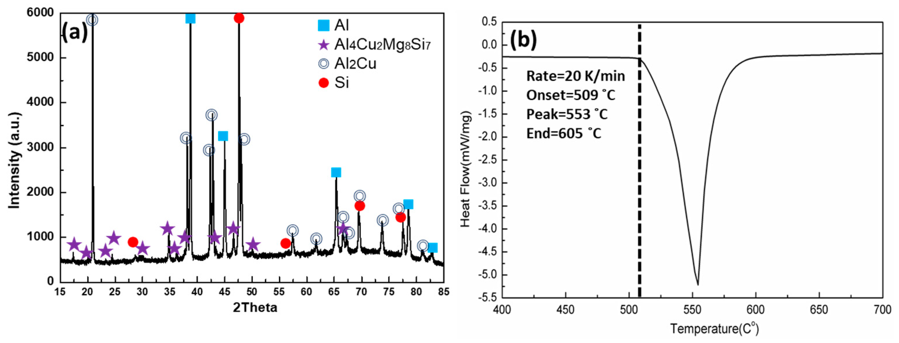
  • The quaternary eutectic alloy solidifies with four distinct solid phases (α-Al, Si, Al2Cu and Al4Cu2Mg8Si7 (Q)), and one endothermic DSC peak with a melting point of 509 °C.
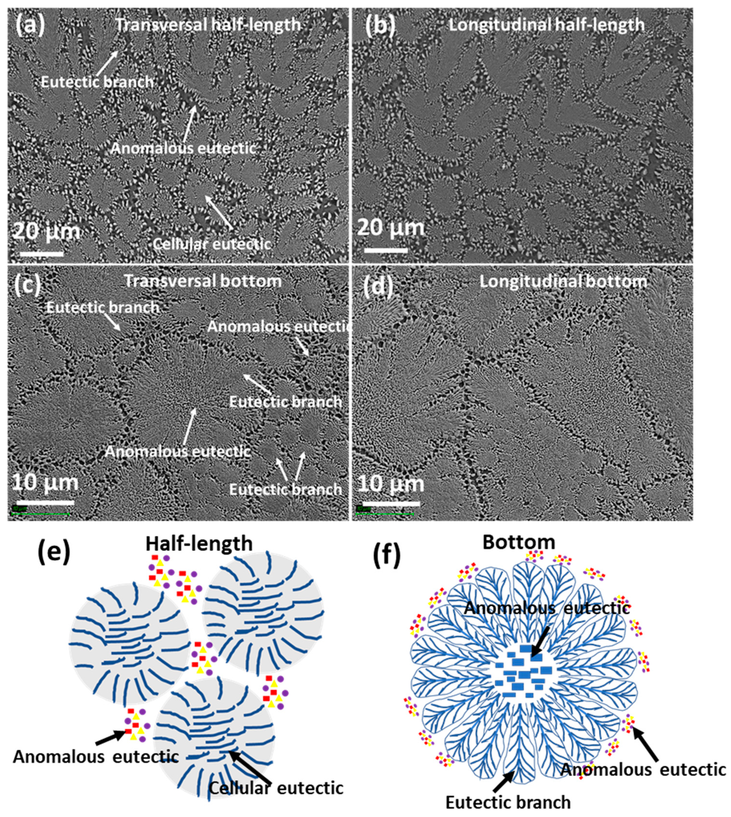
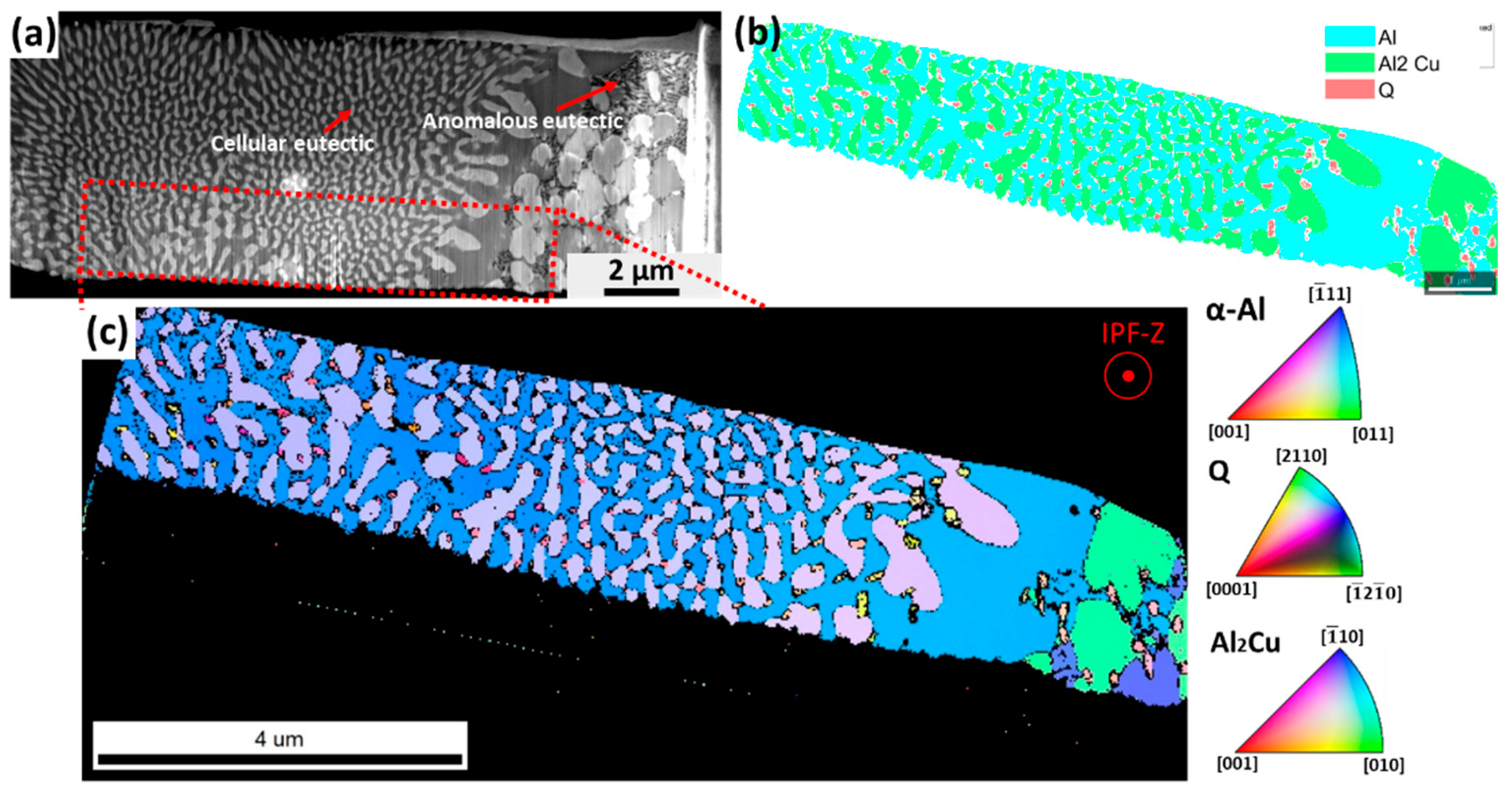
  • The as-cast microstructure of the quaternary eutectic alloy consists of cellular eutectic and fine anomalous eutectic in the intercellular regions. Both eutectic microstructures exhibit four solid phases (α-Al, Si, Al2Cu and Al4Cu2Mg8Si7 (Q)). A cellular eutectic with surrounding branches was found in the fastest cooled part of the sample.
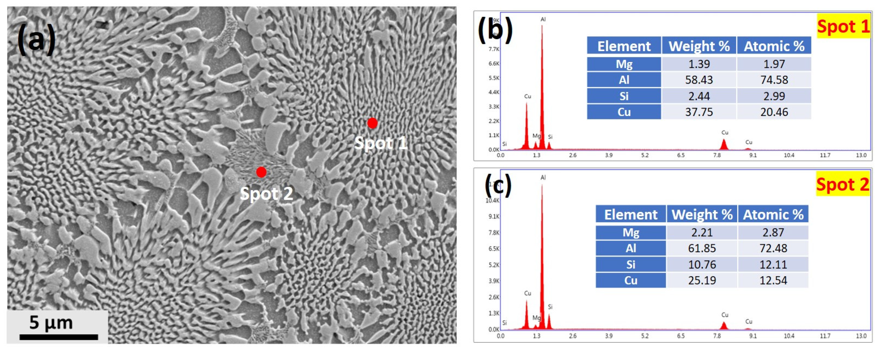
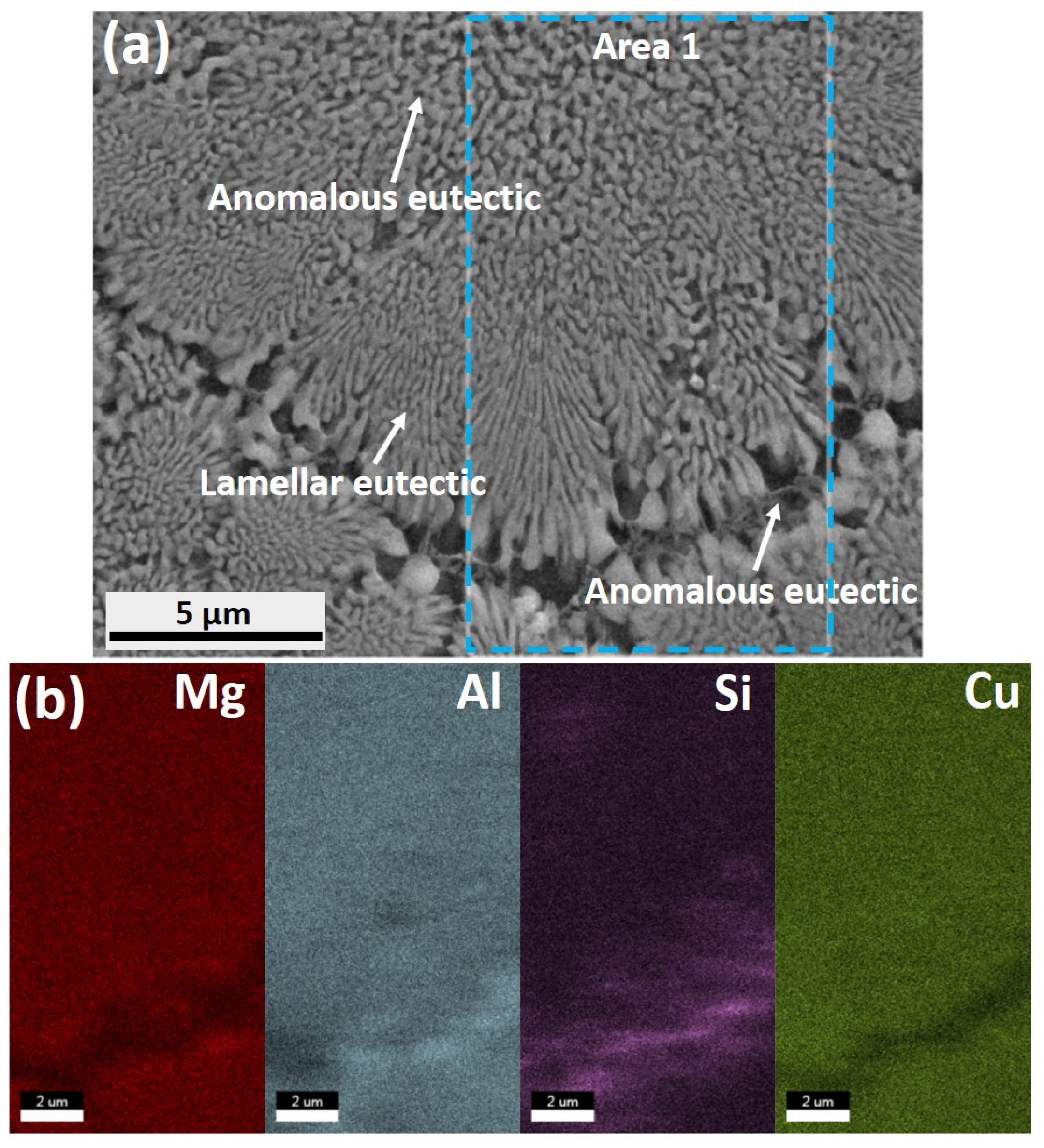
  • A well-defined orientation relationship between the α-Al, Al2Cu and Q phases was found in the centres of the cells, with { 211 } Al2Cu / / { 111 } Al   / / { 31 4 ¯ 0 } Q   and 120 Al2Cu / / 110 Al / / 0001 Q . However, at the cellular boundaries, decoupled growth of Q phase was also found.
  • The alloy shows an excellent compressive yield strength of 835 ± 35MPa, with a moderate compressive fracture strain of 4.7 ± 1.1%. The propagation of cracks along cell boundaries is the main factor leading to the catastrophic failure of the sample.

Supplementary Materials

The following supporting information can be downloaded at: https://www.mdpi.com/article/10.3390/met12010007/s1, Video S1.

Author Contributions

Q.C.: Conceptualization, Methodology, Investigation, Writing—original draft, Review and editing. B.C.: Methodology, Investigation, Review and editing. V.S.T.: Methodology, Investigation. F.W.: Methodology, Investigation. C.L.M.: Methodology, Investigation, Review & editing. I.T.H.C.: Conceptualization, Review & editing, Supervision. Z.F.: Methodology, Investigation, Supervision. All authors have read and agreed to the published version of the manuscript.

Funding

The authors gratefully acknowledge support from the Engineering and Physical Sciences Research Council (EPSRC) for the financial support on Future Liquid Metal Engineering (LiME) Hub (EP/N007638/1).

Data Availability Statement

Not applicable.

Acknowledgments

Qing Cai is very grateful to Brunel University London for the financial support on his PhD studies. The authors would thank Experimental Techniques Centre Brunel University London for access to the characterisation facilities.

Conflicts of Interest

The authors declare no conflict of interest.

References

  1. Mortensen, A.; Jin, I. Solidification processing of metal matrix composites. Int. Mater. Rev. 1992, 37, 101–128. [Google Scholar] [CrossRef]
  2. Bewlay, B.P.; Lipsitt, H.A.; Jackson, M.R.; Reeder, W.J.; Sutliff, J.A. Solidification processing of high temperature intermetallic eutectic-based alloys. Mater. Sci. Eng. A 1995, 192–193, 534–543. [Google Scholar] [CrossRef]
  3. Dahle, A.K.; Nogita, K.; McDonald, S.D.; Dinnis, C.; Lu, L. Eutectic modification and microstructure development in Al-Si Alloys. Mater. Sci. Eng. A 2005, 413–414, 243–248. [Google Scholar] [CrossRef]
  4. Tiwary, C.S.; Pandey, P.; Sarkar, S.; Das, R.; Samal, S.; Biswas, K.; Chattopadhyay, K. Five decades of research on the development of eutectic as engineering materials. Prog. Mater. Sci. 2022, 123, 100793. [Google Scholar] [CrossRef]
  5. Winegard, W.C.; Majka, S.; Thall, B.M.; Chalmers, B. Eutectic solidification in metals. Can. J. Chem. 1951, 29, 320–327. [Google Scholar] [CrossRef] [PubMed] [Green Version]
  6. Elliott, R. Eutectic solidification. Mater. Sci. Eng. 1984, 65, 85–92. [Google Scholar] [CrossRef]
  7. Zener, C. Kinetics of the decomposition of austenite. Trans. Am. Inst. Min. Metall. Eng. 1946, 167, 550–595. [Google Scholar]
  8. Hunt, J.; Chilton, J. Rod transition in binary eutectics. J. Inst. Met. 1963, 92, 338. [Google Scholar]
  9. Jackson, K.A.; Hunt, J.D. Lamellar and Rod Eutectic Growth. In Dynamics of Curved Fronts; Elsevier: New York, NY, USA, 1988; pp. 363–376. ISBN 9780080925233. [Google Scholar]
  10. Trivedi, R.; Magnin, P.; Kurz, W. Theory of eutectic growth under rapid solidification conditions. Acta Metall. 1987, 35, 971–980. [Google Scholar] [CrossRef]
  11. Zimmermann, M.; Carrard, M.; Kurz, W. Rapid solidification of Al-Cu eutectic alloy by laser remelting. Acta Metall. 1989, 37, 3305–3313. [Google Scholar] [CrossRef]
  12. Mullis, A.M.; Clopet, C.R. On the origin of anomalous eutectic growth from undercooled melts: Why re-melting is not a plausible explanation. Acta Mater. 2018, 145, 186–195. [Google Scholar] [CrossRef]
  13. Li, J.F.; Jie, W.Q.; Zhao, S.; Zhou, Y.H. Structural evidence for the transition from coupled to decoupled growth in the solidification of undercooled Ni-Sn eutectic melt. Metall. Mater. Trans. A Phys. Metall. Mater. Sci. 2007, 38, 1806–1816. [Google Scholar] [CrossRef]
  14. Goetzinger, R.; Barth, M.; Herlach, D.M. Mechanism of formation of the anomalous eutectic structure in rapidly solidified Ni-Si, Co-Sb and Ni-Al-Ti. Acta Mater. 1998, 46, 1647–1655. [Google Scholar] [CrossRef]
  15. Lin, X.; Cao, Y.Q.; Wang, Z.T.; Cao, J.; Wang, L.L.; Huang, W.D. Regular eutectic and anomalous eutectic growth behavior in laser remelting of Ni-30wt%Sn alloys. Acta Mater. 2017, 126, 210–220. [Google Scholar] [CrossRef]
  16. Kim, Y.S.; Park, H.J.; Kim, J.T.; Hong, S.H.; Park, G.H.; Park, J.M.; Suh, J.Y.; Kim, K.B. Influence of Nb on microstructure and mechanical properties of Ti-Sn ultrafine eutectic alloy. Met. Mater. Int. 2017, 23, 20–25. [Google Scholar] [CrossRef]
  17. Kang, J.L.; Xu, W.; Wei, X.X.; Ferry, M.; Li, J.F. Solidification behavior of Co-Sn eutectic alloy with Nb addition. J. Alloys Compd. 2017, 695, 1498–1504. [Google Scholar] [CrossRef]
  18. Zhao, S.; Li, J.; Liu, L.; Zhou, Y. Solidification of undercooled Ag-Cu eutectic alloy with the Sb addition. J. Alloys Compd. 2009, 478, 252–256. [Google Scholar] [CrossRef]
  19. Pandey, P.; Kashyap, S.; Tiwary, C.S.; Chattopadhyay, K. Development of High-Strength High-Temperature Cast Al-Ni-Cr Alloys Through Evolution of a Novel Composite Eutectic Structure. Metall. Mater. Trans. A Phys. Metall. Mater. Sci. 2017, 48, 5940–5950. [Google Scholar] [CrossRef]
  20. De Wilde, J.; Froyen, L.; Rex, S. Coupled two-phase [α(Al) + θ(Al2Cu)] planar growth and destabilisation along the univariant eutectic reaction in Al-Cu-Ag alloys. Scr. Mater. 2004, 51, 533–538. [Google Scholar] [CrossRef]
  21. Song, G.A.; Han, J.H.; Lim, K.R.; Kim, T.E.; Park, J.M.; Kim, D.H.; Park, J.Y.; Seo, Y.; Kim, K.B. Optimization of mechanical properties of Ti-Fe-Sn alloys by controlling heterogeneous eutectic structure. Intermetallics 2012, 23, 27–31. [Google Scholar] [CrossRef]
  22. Genau, A.L.; Ratke, L. Crystal orientation and morphology in Al-Ag-Cu ternary eutectic. IOP Conf. Ser. Mater. Sci. Eng. 2011, 27, 012032. [Google Scholar] [CrossRef] [Green Version]
  23. Tiwary, C.S.; Kashyap, S.; Chattopadhyay, K. Development of alloys with high strength at elevated temperatures by tuning the bimodal microstructure in the Al-Cu-Ni eutectic system. Scr. Mater. 2014, 93, 20–23. [Google Scholar] [CrossRef]
  24. Sprenger, H.; Richter, H.; Nickl, J.J. Unidirectional solidification of Ni-Mo-Al eutectic alloys. J. Mater. Sci. 1976, 11, 2075–2081. [Google Scholar] [CrossRef]
  25. Lee, C.H.; Hong, S.H.; Kim, J.T.; Park, H.J.; Song, G.A.; Park, J.M.; Suh, J.Y.; Seo, Y.; Qian, M.; Kim, K.B. Chemical heterogeneity-induced plasticity in Ti-Fe-Bi ultrafine eutectic alloys. Mater. Des. 2014, 60, 363–367. [Google Scholar] [CrossRef]
  26. Kim, J.T.; Lee, S.W.; Hong, S.H.; Park, H.J.; Park, J.Y.; Lee, N.; Seo, Y.; Wang, W.M.; Park, J.M.; Kim, K.B. Understanding the relationship between microstructure and mechanical properties of Al-Cu-Si ultrafine eutectic composites. Mater. Des. 2016, 92, 1038–1045. [Google Scholar] [CrossRef]
  27. Hötzer, J.; Steinmetz, P.; Dennstedt, A.; Genau, A.; Kellner, M.; Sargin, I.; Nestler, B. Influence of growth velocity variations on the pattern formation during the directional solidification of ternary eutectic Al-Ag-Cu. Acta Mater. 2017, 136, 335–346. [Google Scholar] [CrossRef]
  28. Park, E.M.; Lee, C.H.; Park, J.M.; Han, J.H.; Song, G.A.; Kim, J.T.; Hong, S.H.; Park, J.Y.; Seo, Y.; Lee, N.S.; et al. Heterogeneous duplex structured Ti-Sn-Mo alloys with high strength and large plastic deformability. J. Alloys Compd. 2013, 574, 546–551. [Google Scholar] [CrossRef]
  29. Chanda, B.; Potnis, G.; Jana, P.P.; Das, J. A review on nano-/ultrafine advanced eutectic alloys. J. Alloys Compd. 2020, 827, 154226. [Google Scholar] [CrossRef]
  30. Stepanov, N.D.; Shaysultanov, D.G.; Tikhonovsky, M.A.; Salishchev, G.A. Tensile properties of the Cr-Fe-Ni-Mn non-equiatomic multicomponent alloys with different Cr contents. Mater. Des. 2015, 87, 60–65. [Google Scholar] [CrossRef]
  31. Eckert, H.; He, G.; Das, J.; Loser, W. Nanostructured composites in multicomponent alloy systems. Mater. Trans. 2003, 44, 1999–2006. [Google Scholar] [CrossRef] [Green Version]
  32. Mondol’fo, L. Aluminum Alloys-Structure and Properties; Butterworths and Co., Ltd.: London, UK, 1976.
  33. Kayg, Y.; Maras, N. Directional solidification of Al-Cu-Si-Mg quaternary eutectic alloy. J. Alloys Compd. 2017, 721, 764–771. [Google Scholar] [CrossRef]
  34. Chang, I.; Cai, Q. From simple binary to complex multicomponent eutectic alloys. Prog. Mater. Sci. 2022, 123, 100779. [Google Scholar] [CrossRef]
  35. Li; Kuribayashi Nucleation-controlled microstructures and anomalous eutectic formation in undercooled Co-Sn and Ni-Si eutectic melts. Metall. Mater. Trans. A 2003, 34, 2999–3008. [CrossRef]
  36. Zhao, S.; Li, J.F.; Liu, L.; Zhou, Y.H. Cellular growth of lamellar eutectics in undercooled Ag-Cu alloy. Mater. Charact. 2009, 60, 519–524. [Google Scholar] [CrossRef]
  37. Mullins, W.W.; Sekerka, R.F. Stability of a planar interface during solidification of a dilute binary alloy. J. Appl. Phys. 1964, 35, 444–451. [Google Scholar] [CrossRef]
  38. Cantor, B.; Chadwick, G.A.A. Crystallography of Al-Al3Ni, Al-Al2Cu and Al-ζ(AlAg) eutectics during nucleation and the early stages of growth. J. Cryst. Growth 1975, 30, 101–108. [Google Scholar] [CrossRef]
  39. Ruggiero, M.A.; Rutter, J.W. Origin of microstructure in the 332 K eutectic of the Bi-In-Sn system. Mater. Sci. Technol. 1997, 13, 5–11. [Google Scholar] [CrossRef]
  40. Srivastava, R.M.; Eckert, J.; Löser, W.; Dhindaw, B.K.; Schultz, L. Cooling Rate Evaluation for Bulk Amorphous Alloys from Eutectic Microstructures in Casting Processes. Mater. Trans. 2002, 43, 1670–1675. [Google Scholar] [CrossRef] [Green Version]
  41. Pawlik, P.; Pawlik, K.; Przybł, A. Investigation of the cooling rate in the suction casting process. Rev. Adv. Mater. Sci. 2008, 18, 81–84. [Google Scholar]
  42. Abbaschian, R.; Lipschutz, M.D. Eutectic solidification processing via bulk melt undercooling. Mater. Sci. Eng. A 1997, 226–228, 13–21. [Google Scholar] [CrossRef]
  43. Kim, S.H.; Lee, H.; Yeon, S.M.; Aranas, C.; Choi, K.; Yoon, J.; Yang, S.W.; Lee, H. Selective compositional range exclusion via directed energy deposition to produce a defect-free Inconel 718/SS 316L functionally graded material. Addit. Manuf. 2021, 47, 102288. [Google Scholar] [CrossRef]
  44. Trivedi, R.; Kurz, W. Morphological stability of a planar interface under rapid solidification conditions. Acta Metall. 1986, 34, 1663–1670. [Google Scholar] [CrossRef]
  45. Li, Q.; Beckermann, C. Evolution of the sidebranch structure in free dendritic growth. Acta Mater. 1999, 47, 2345–2356. [Google Scholar] [CrossRef]
  46. Wei, X.X.; Lin, X.; Xu, W.; Huang, Q.S.; Ferry, M.; Li, J.F.; Zhou, Y.H. Remelting-induced anomalous eutectic formation during solidification of deeply undercooled eutectic alloy melts. Acta Mater. 2015, 95, 44–56. [Google Scholar] [CrossRef]
  47. Cantor, B.; Chadwick, G.A. The tensile deformation of unidirectionally solidified AI-Al3Ni and Al-Al2Cu eutectics. J. Mater. Sci. 1975, 10, 578–588. [Google Scholar] [CrossRef]
  48. Nabarro, F.R.N.; Duesbery, M.S.; Hirth, J.P. Dislocations in Solids; North-Holland Publishing Co.: Amsterdam, The Netherlands, 1979; ISBN 9780444850041. [Google Scholar]
  49. Bramfitt, B.L. The Effect of Carbide and Nitride Additions on the Heterogeneous Nucleation Behavior of Liquid Iron. Metall. Trans. 1970, 1, 1987–1995. [Google Scholar] [CrossRef]
  50. Kurz, W.; Trivedi, R. Eutectic growth under rapid solidification conditions. Metall. Trans. A 1991, 22, 3051–3057. [Google Scholar] [CrossRef]
  51. Park, J.M.; Kim, K.B.; Kim, D.H.; Mattern, N.; Li, R.; Liu, G.; Eckert, J. Multi-phase Al-based ultrafine composite with multi-scale microstructure. Intermetallics 2010, 18, 1829–1833. [Google Scholar] [CrossRef]
  52. Lei, Q.; Ramakrishnan, B.P.; Wang, S.; Wang, Y.; Mazumder, J.; Misra, A. Structural refinement and nanomechanical response of laser remelted Al-Al2Cu lamellar eutectic. Mater. Sci. Eng. A 2017, 706, 115–125. [Google Scholar] [CrossRef]
  53. Cantor, B.; May, G.J.; Chadwick, G.A. The tensile fracture behaviour of the aligned Al-Al3Ni and Al-CuAl2 eutectics at various temperatures. J. Mater. Sci. 1973, 8, 830–838. [Google Scholar] [CrossRef]
  54. Park, J.M.; Kim, D.H.; Kim, K.B.; Kim, W.T. Deformation-induced rotational eutectic colonies containing length-scale heterogeneity in an ultrafine eutectic Fe83Ti7Zr6B4 alloy. Appl. Phys. Lett. 2007, 91, 131907. [Google Scholar] [CrossRef]
  55. Kim, J.T.; Hong, S.H.; Park, J.M.; Eckert, J.; Kim, K.B. Microstructure and mechanical properties of hierarchical multi-phase composites based on Al-Ni-type intermetallic compounds in the Al-Ni-Cu-Si alloy system. J. Alloys Compd. 2018, 749, 205–210. [Google Scholar] [CrossRef]
Figure 1. Schematic diagram showing the locations for metallography and compression test specimens.
Metals 12 00007 g001
Figure 2. (a) XRD spectrum of Al−Cu−Si−Mg eutectic alloy (b) DSC curve of Al−Cu−Si−Mg eutectic alloy with a heating rate of 20 K/min.
Metals 12 00007 g002
Figure 3. SEM secondary electron images showing the microstructure of half-length of the sample (a) transversal (b) longitudinal; the microstructure of the bottom part (c) transversal (d) longitudinal; schematic of the microstructure in half-length (e) bottom (f).
Metals 12 00007 g003
Figure 4. (a) SEM secondary electron image taken from a transverse section at half-length of the sample under high magnification (b,c) SEM-EDX point analyses of Spot 1 and Spot 2 obtained from (a).
Metals 12 00007 g004
Figure 5. (a) SEM secondary electron image taken from the transversal bottom part of the sample under high magnification (b) SEM-EDX mapping of Area 1 in (a).
Metals 12 00007 g005
Figure 6. TEM bright-field image of (a) the microstructure taken from the cell centre and (b) corresponding SADPs of Al, Si, Q and Al2Cu phases.
Metals 12 00007 g006
Figure 7. (a) SEM image showing the FIB-milled lamella (b) SEM-TKD map of eutectic phases distribution (c) inverse pole figure (IFP) map of the eutectic region taken from the area marked in (a), showing the inverse pole figure directions along IPF-Z.
Metals 12 00007 g007
Figure 8. (a) SEM image showing the FIB-milled lamella (b) IPF-Z map of α-Al, Al2Cu and Q phases at cell boundary (c) pole figures for identification of the orientation relationship between the three phases including α-Al, Al2Cu and Q.
Metals 12 00007 g008
Figure 9. Compressive stress and strain of quaternary Al-Cu-Si-Mg eutectic alloy.
Metals 12 00007 g009
Figure 10. (a) SEM backscattered image of fracture surface at low magnification (b,c) high-magnified SEM images of areas (A, B) marked by yellow circles in (a).
Metals 12 00007 g010
Figure 11. (a) bright-field TEM image of quaternary eutectic alloy after compression test (b) enlarged TEM BF images of cellular regions taken from Area 1.
Metals 12 00007 g011
Figure 12. The suggested fracture mechanism of bimodal quaternary Al-Cu-Si-Mg alloy.
Metals 12 00007 g012
Table 1. The compressive mechanical properties of current and reported Al-based ultrafine eutectic alloys.
Alloy Composition
/Atomic Percent
Sample Size
/mm
Yield Strength
/MPa
Fracture Strength
/MPa
Plastic Strain
/%
Al83Cu17 [51]∅1~1000~1200~2
Al81Cu13Si6 [26]∅3~773~1000~8
Al81Ni13Si6 [55]∅35025565.2
Al81Ni5Cu8Si6 [55]∅359877314.8
Al88Cu10.5Ni1.5 [23]∅380010009
Al96.9Ni3.1 [19]∅3~210~350~20
Al95.4Ni4Cr0.6 [19]∅3~380~800~35
Al77.1Cu13.6Mg3Si6.3
(current work)
∅3~835~1036~4.7
Publisher’s Note: MDPI stays neutral with regard to jurisdictional claims in published maps and institutional affiliations.

