Abstract
The gas turbine engine’s (GTE) development aims for the increasing the efficiency, strength, reliability and safety of its components. To create competitive engines, housing parts and components with high functionality and reduced weight are needed. Especially difficult in the design and production are the gearboxes for aviation GTE. Traditional technologies based on precision casting or material forming operations have significant limitations due to the complexity of fulfilling multiple different requirements. Nowadays, one of the progressive production techniques is additive manufacturing. The article presents the results of computational and experimental studies that substantiate the applicability of laser additive technology to reduce the mass of body parts by up to 15% while ensuring their strength properties. The physical and mechanical characteristics of aluminum alloys acceptable for the manufacturing of housing parts were analyzed. The necessary characteristics of the powder alloy of the Al-Si system and the technological parameters of the L-PBF of the modified housing of the gear reducer are established. Using the finite element method (FEM) the L-PBF process was numerically simulated and the technological modes for synthesis of the AlSi10Mg alloy powder were optimized. With the help of a serial 3D printer ProX320DMP, the prototype of a gear housing was manufactured.
1. Introduction
Additive technology (AT) of laser powder bed fusion (L-PBF) as a part of the promising and progressive concept of digital production for manufacturing modern aviation products is currently on the rise in industry [1,2,3,4,5,6,7]. Selective laser melting (SLM), which represents one of the L-PBF technologies belonging to one of the prospective technologies worldwide. The design and production of parts of complex spatial forms must be carried out in the shortest possible time, involving the concept of “unlimited complexity”. In many ways, this applies to the design and manufacture of gas turbine engines (GTE) gearboxes, which have a complex spatial configuration and which undergo significant static and dynamic loads. The rotating of shafts and gears of the input stage causes the appearing of meaningful dynamic loads at an angular speed that exceeds 2.0 × 10⁴ rpm. In this case, shock and cyclic loads are arising and transmitting through the bearings to the housing of the input stage.
Today, the traditional and the most common applied method of manufacturing of housing half-parts is complex-shaped casting of Al-based alloys, which have a tensile strength within the range of 167–294 MPa. The casting technology of aluminum housings has a number of significant drawbacks which can be found elsewhere [8,9]. There are the low quality of castings due to gas porosity, the presence of non-metallic inclusions, high surface roughness and low geometric accuracy, multi-operability of subsequent machining, and the long time required in the manufacturing process.
Additive technology of L-PBF makes it possible to eliminate a significant part of the above-mentioned disadvantages. At the same time, this technology provides greater design freedom, refining and optimizing a new design to create less massive and more efficient products for further production [10]. The problem of weight reduction of high-loaded hull structures while maintaining their strength properties is a complex task. To solve it, a number of comparative studies are required, such as strength characterization of the original structure and its modifications, topology optimization of the modified 3D model, numerical simulation of the 3D printing process using operating parameters, coupled with the technical specification of the 3D printer, metallographic analysis and static strength and cyclic durability.
In fact, the methodology of laser-powder additive growing of housing parts according to the initial 3D model with a minimum mass embodies the synergetic principle “from complexity to holistic simplicity”. At the same time, the apparent simplicity for numerical simulation needs the numerous laboratory tests and the developing of new testing approaches to get the parameters not used in prior technologies, e.g., casting or forging, and for new material compositions. The various methods for powder characterization after the basic material atomization, among them the laser diffraction and scanning electron microscopy or SEM; mechanical uniaxial tensile or three-point bend tests for getting mechanical properties; simulation of the static and dynamic loading problems for the localization of the potential optimization fields of interests and 3D-printing for choosing the right technological parameters can be found separately in a wide range of the research papers. However, the complex approach needs the cooperation and merging of the results of separated researcher group together. This brings forth new pitfalls and project milestones for ready-to-use printing technology in mass scale production that are not always evident in the first trial stages.
2. Materials and Methods
There are many studies using various aluminum powder materials for laser additive machine manufacturing techniques [11,12,13]. They contain schemes that reveal all of the main stages of the additive production process—from the slicing of the original 3D model before unloading the printed sample. In the reviews, it is noted that, in contrast to cast and forged aluminum alloys, additively grown powder alloys are formed in highly non-equilibrium conditions that are inherent in laser micrometallurgia. In particular, according to the theory of solidification, the size of dendritic grains by a power depends on the cooling rate. The latter, in turn, is determined on the macro level, primarily the power of the laser beam, the speed of scanning, its strategy. The use of key patterns made it possible to establish experimentally confirmed modest parameters of the synthesis of samples from aluminum powder alloys that do not contain metallurgical defects. For the preparation of samples with mechanical properties at the routine level, a large number of experiments are required. Today, very little work is aimed at the study of interrelated processes of additive cultivation based on numerical modeling and simulation of the process in order to minimize experimental work.
Generally, as discussed elsewhere [14], the gap in description of the mechanical properties of aluminum powder alloys for 3D printing emphasize the lack of material behavior under high strain rates and under dynamic loads. When designing gear drive housings, aluminum alloys of the Al-Si system are used, which have acceptable corrosion properties and strength characteristics. In the present study, aluminum powder alloy AlSi10Mg (CL 31 AL) was used. This alloy is a general-purpose aluminum-silicon alloy powder for additive manufacturing of products operating under high mechanical and dynamic loads, both in the field of engine building and aerospace [15]. A study on the development of 3D printing regimes of witness samples and the gearbox housing was carried out on a serial 3D printing system ProX320DMP with L-PBF technology. The design, topology optimization and modification of the original housing was carried out in the ANSYS software.
To simulate the process of 3D printing and calculate the stress-strain state or SSS of the modified hull structure, Altair Inspire, module Print3D was used, which allows for the estimation of the magnitude of possible warping and maximum temperature. Uniaxial tensile tests for the samples made from the synthesized alloy were carried out according to standards GOST 1497–84 and GOST 9652–84 on the LFV100HH testing machine at a ram speed of 5.0 × 10⁻³ mm/s under normal conditions. The microhardness of the sample was measured with the microhardness tester FM-31. The microhardness measurement of this equipment is based on the Vickers method. The load used is 300 g.
Metallographic studies of the powder composition and witness samples made from the AlSi10Mg alloy were carried out using an Olympus optical microscope, a Tescan Mira 3 scanning electron microscope with an Oxford Instruments EDX analysis attachment, and an EBSD attachment. To increase the effectiveness of metallographic SEM and EBSD analysis, the studied surfaces of the samples were treated with the sand paper (SiC) with a grain size of up to 1200 grit and additionally polished with an aluminum suspension of 9 and 3 μm, and finally polished with colloidal silica particle of 0.25 μm [10]. The sample surfaces were etched for microstructural analysis using a solution of 1 mL HF + 2 mL HNO3 + 50 mL H2O for 15 s. The sample for EBSD analysis was polished using vibration polishing for one day.
3. Modification of the Gear Housing
The desired 3D model of the lower angular gearbox housing was originally designed for manufacturing using foundry technology. The SSS of the original hull structure was calculated in order to determine the zones, which are clearly have “extra” material to be removed. These small areas of interest can be modified without significantly affecting the adjacent bigger partitions of the housing. The general view of the model and the modification areas are given in Figure 1a,b respectively. In the Figure 1b there are several areas: (1) a massive connection with a variable thickness, converted into an element of a constant thickness of ~30% from the maximal value; (2) the thickness of the tidal wall is reduced by ~18%; and (3) well for bolts placement with the reduced value of the walls by ~50%. Modification of the gearbox housing was performed by the finite element method (FEM) using the ANSYS software package [16]. The mass of the aluminum gearbox housing was successfully reduced rather than the weight of the original part by 15% while meeting the strength requirements (Table 1). Materials’ characteristics powder Aluminum AlSi10Mg are next [17]: tensile strength = 430 MPa), yield point = 245 MPa, elongation = 9%. The minimum factor of the safety of the modified structure is more 5. It is enough for the specified operating conditions.
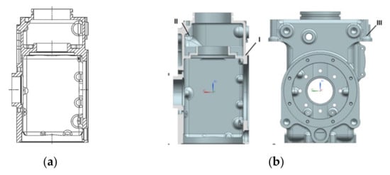
Figure 1.
Lower angular gearbox housing: original design (a) and modification areas (b).

Table 1.
Comparative results of strength characteristics of the original and modified structure.
4. Characterization of Powder Aluminum Material
The batch of powder used for 3D printing was subjected to the granulometric analysis and the basic metallographic analysis. The particle size was measured from electron backscattering (BSE) images on base the ImageJ software. The average values were calculated based on the results of 100 measurements collected from a 350 × 350 µm area. Figure 2a shows a panoramic BSE image of AlSi10Mg particles and Figure 2b shows the diagram of particle size distribution.
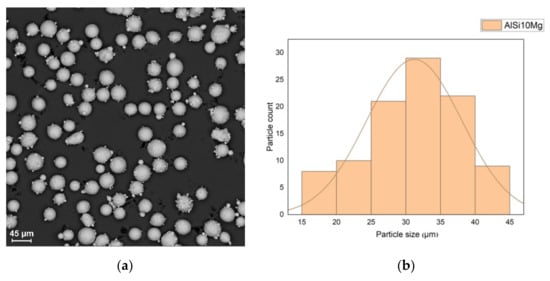
Figure 2.
Particle size analysis: panoramic BSE image (a) and particle size distribution (b).
There are satellites on the surface of the particles, which is an acceptable defect. In addition, there are some agglomerates of particles. The particle size is in range of 15–45 μm. The powder particles are mostly spherical, but 3% of the particles were recognized as lamellar. Figure 3 shows the morphology of the particles. The results of chemical analysis at several points are summarized in Table 2. The content of magnesium, aluminum and silicon meets the requirements of DIN EN 1676-1996.
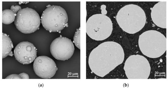
Figure 3.
Particle morphology: surface (a) and cross-section cut (b).

Table 2.
Results of chemical analysis of AlSi10Mg powder.
The obtained results indicate the possibility of using the AlSi10Mg powder composition in additive manufacturing, which is only a necessary condition. As a criterion for the applicability of the additive manufacturing method for body parts, it is convenient to use the triune parameters “productivity—manufacturing accuracy—strength properties”. In contrast to the dual criterion of the “bad—good” type, in such a triad criterion, one of the parameters (the main one) acts as an arbitrator for the other two, which are in a state of mutual complementarity. Without taking into account the triad, the productivity and accuracy of manufacturing parts through 3D printing are perceived as opposite concepts. Striving for accuracy, they sacrifice productivity; achieving productivity, they do not expect high accuracy. However, with the orientation of the growing process to obtain the required strength properties, the contradiction is resolved [18].
5. Optimization of the Laser Synthesis Process of the Gearbox Housing
Based on the above approach, the L-PBF method of additive manufacturing was chosen for the modified hull design. As can be seen from the diagram shown in Figure 4, the process of laser additive 3D growing of metal parts of a powder composition is determined by many factors. The analysis and systematization of significant factors makes it possible to assume that among the many variables operating in the laser technology system, only a few basic, so-called order parameters are determining, to which the rest are adjusted. Such, as it seems to us, are energy thermal parameters.
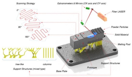
Figure 4.
The strategy and melting pool of laser-based additive process during 3D printing.
5.1. Energy Thermal Calculation
According to the literature data [19], the local melting of the powder in the zone of laser exposure to a dispersed medium occurs in a small range of power density (intensity, I0) of radiation. Due to the fact that at a higher power density of the laser beam in the heating zone, not only the melting of powder particles occurs, but also the formation of a plasma torch, which negatively affects the kinetics of the melting process. A decrease in the power density below 108 W/m2 leads to a loss of uniformity of the powder melt and the appearance of teardrop-shaped discontinuities in the formed layer. Therefore, in order to avoid instabilities and defects, the condition (1) should be fulfilled for optimal radiation power density in the heating spot.
108 ≤ I0 ≤ 1010 [W/m2]
The intensity I0 of the radiation incident on the irradiated surface is determined through the power of the laser beam W and the area of the focus spot as follows: I0 = 4 W/πd2. At the same time, it should be noted that the duration of heating of the powder substance corresponds to the time constant τ, which represents the exposure time, when the laser radiation passes through a certain point on the surface at a scanning speed v. Since the radiation is focused into a spot with a diameter d, then naturally τ = d/v.
Then the thermal effect of the laser beam on the powder, taking into account the optical absorption coefficient α, can be represented as a surface source with a density WL = αI0, acting for a time τ. During this time, the wave of thermal conductivity will spread into the powder layer to a depth of z.
Heat transfer in a powder medium has its own characteristics, since the bulk density of the powder; the size and shape of the powder particles determine the thermo-physical characteristics of the desired dispersed medium. In this regard, a method is proposed for averaging the thermo-physical characteristics of aluminum powder [20] based on the given values of thermal conductivity λ′ = (1 − ε)λ, heat capacity C′ = (1 − ε)C, density p′ = (1 − ε)p, respectively. Here λ, C, p are the values of thermal conductivity, heat capacity, density of the compact material from which the powder is created. With layer-by-layer laser melting, the heat transfer process can be considered within the framework of a single (in depth) linear approximation and not take into account the temperature dependence α, ε, λ, C, p. In this formulation, the depth of the molten layer z will be determined according to Equation (2).
where a′ = λ′/C′p′ is the average coefficient of thermal conductivity of the powder.
Due to the equality of the energy flow absorbed and withdrawn from the surface due to thermal conductivity, it can be represented through Equation (3), so the required laser power W was calculated by substituting the known powder melting point and the exposure time.
5.2. Optimization of Laser Synthesis Modes
As a criterion for the energy efficiency of laser SLM increasing, it is rational to use the value of the specific energy input of Ey (J/mm2) in form of Equation (4).
where v [mm/s] is the scanning rate, b [mm] is the building step.
Expression (4) is easy to compare with the known operating parameters [21], since the value of b is set based on previous experiments; while the laser beam, power and scanning rate are inversely proportional to each other.
In the steady-state building mode, it is convenient to optimize the SLM process using a dimensionless similarity criterion Pe (similarly to the Peclet criterion), which characterizes the rate of introduction of laser energy relative to the rate of its dissipation during laser working, as in Equation (5).
Using the values of the thermo-physical characteristics of the AlSi10Mg powder, taking into account its bulk density, given in Table 3, and the above-described methodology, the technological regimes of layer-by-layer synthesis of the gearbox housing were optimized. The results are summarized in Table 4.

Table 3.
Thermo-physical characteristics of the AlSi10Mg alloy

Table 4.
Technological characteristics of printing process for gearbox housing
5.3. Simulation of the SLM Process
Now many investigations target the numerical approaches for better understanding the interactions between the material and technological responded parameters. Too many variations of the process results disturb the straight going towards the better results. In this case the entry quality material tests and simulation can give the best result and make the forecast for the warpage free prototype. The right orientation and temperature stabilizing structures reduce the residual stresses, so the warpage decreases.
The finite element simulation of the 3D printing process was performed in the solidThinking Inspire software package using the Print3D module [22]. To do this, the operating parameters from Table 4 were used. The task of simulating the process was solved in a thermomechanical formulation. Figure 5 shows the sequence of stages in pre-processor: placing a 3D model on the base plate of the printing chamber (a); generating the support structures (b); slicing the model (c).
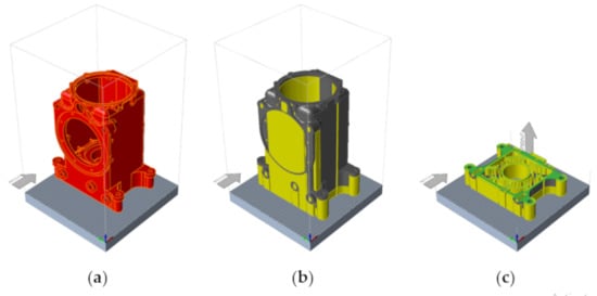
Figure 5.
Stages of pre-processing: placing and orientation in chamber (a), support generation (b) and slicing (c).
Figure 6 shows the distribution and values of the temperature field (a), the stress field (b) by Mises and displacements (c) in a virtual grown volume. These images correspond to the final stage of the 3D printing simulation of the gearbox housing, when 100% of the volume of layer-by-layer calculations were performed. The maximal stresses and displacement allocated in the bottom part of the housing. The displacement of ~3.6 mm can damage the first layers an d accumulate the rest stresses from the bottom upwards. Nevertheless, according to the von Mieses stresses its value does not overcome ~128 MPa in most of the points, which is a rather low value for the critical construction damage. In the most places, the displacement does not go over the 1 mm threshold. Therefore, the obtained result has a good chance to grow the housing with the little percentage of warpage. And during the real printing, described in Section 6.2, more rigid support structures, like a fence, was used instead of the simple shell structures. That helps to reduce the displacements by more than 80%.
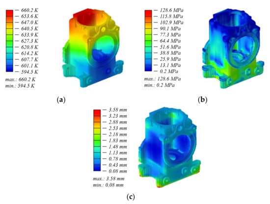
Figure 6.
Output fields in the growing volume: (a) temperature, (b) equivalent stresses and (c) displacements.
Comparing results after topology optimization (Table 1) with the current results (Figure 6), the strong affect of the thermomechanical problem formulation on changing the SSS of material is good to recognize. The difference between the stresses can represent the level of the residual stresses. But this thesis should be checked in future studies.
6. Results of 3D Laser Growing of the Gearbox Housing
6.1. Regimes of 3D Printing
Experimental studies on 3D growing of the gearbox housing made from AlSi10Mg alloy powder were carried out on the 3D printer ProXDMP320 equipped with a 400 W fiber laser. Table 5 shows the range of changes in the parameters that determine the energy-thermal modes of growing witness samples.

Table 5.
Ranges for 3D-printing regimes of samples made from AlSi10Mg.
Taking into account the optimality Peclet criterion (Equation (5)), parameters such as focal length (400 mm), laser spot diameter d (60 μm), powder feed ratio (400%), recoater speed (115 mm/s) and layer thickness (30 μm) were set to constant values, and only power W and speed v were discretely changed. Thus, for each of the nine combinations of W and v, four samples of each orientation were produced.
6.2. Metallographic Analysis of Grown Samples
Figure 7 shows the metallographic macrostructure of the synthesized alloy of the AlSi10Mg system. In optical resolution, the macrostructure has a form characteristic of 3D printing [23]. The structure consists of successive overlapping sections of tracks forming a relief in the form of “fish scales” parallel to the Z-axis, the size of which is in the range of 0.020–0.1 mm.
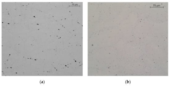
Figure 7.
The structure of the synthesized AlSi10Mg alloy is presented along the Z–axis (a) and in the XY–plane (b).
Figure 7 shows the etched metallographic macrostructure of the synthesized alloy of the AlSi10Mg system. In optical resolution, the macrostructure has a form characteristic of 3D printing [23]. The etching reveals successive overlapping sections of tracks forming a relief in the form of “fish scales” parallel to the Z-axis, the size of which is in the range of 20–100 µm. The study of the macrostructure using an optical microscope revealed no large pores, and the irregularly shaped black areas in Figure 8 are the result of etching of the sample. The sample demonstrates a dendritic structure with a fine cellular interdendritic region, and the dendrites are mostly oriented in the direction of construction. Furthermore, the cells near the cladded bead boundary are larger than in the middle: 0.5–1 microns in the middle and 1.5–2.5 at the boundary.
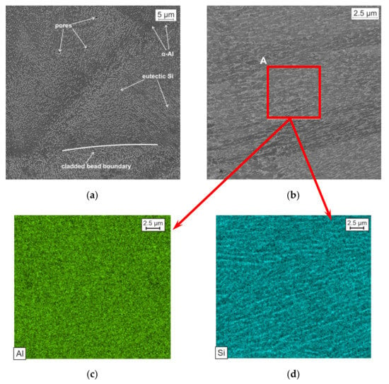
Figure 8.
SE (a) and BSE-image (b) of the AlSi10Mg sample; distribution map of Al (c) and Si (d) in region A on Figure 8b
Figure 8a shows a BSE-image of the sample. The sample contains a small number of micropores of about 2 μm in size. As can be seen from Figure 8, the α-Al grains are surrounded by a eutectic fibrous Si. The presence of such phases is confirmed by the distribution maps of Al and Si in region A on Figure 8b. Such a fine cellular structure has a positive effect on the mechanical and technological properties of the product: the smaller the size of the cells, the higher the plasticity properties.
Figure 9 represents the EBSD data of the AlSi10Mg sample. Related to the results of the EBSD analysis the columnar grains are predominantly oriented in the 001 direction. The grain size is 5–25 μm. Grain orientation is directly related to the mechanical properties of the material. Direction 001 is preferred for obtaining enhanced plastic properties. In the sample there are also joints of grains with different orientation (example on Figure 9), which according to studies [24,25] promotes a high tendency to the nucleation of cracks. However, in the case of this sample, the effect of grain disorientation on crack formation is excluded.
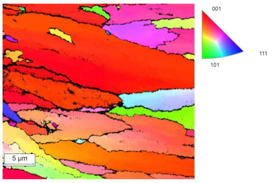
Figure 9.
EBSD data of the AlSi10Mg sample
Figure 10 shows the SE and BSE-image of the fracture cross-section. Elongated grains with the weakly defined boundaries characterize the fracture, which indicates the ductile type of fracture. The fracture occurred along the cladded bead boundaries. The fracture has a large number of facets up to 1 micron in size.
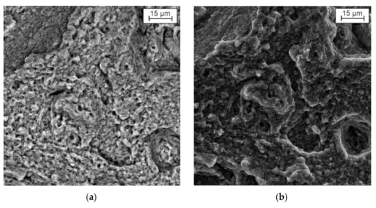
Figure 10.
BSE (a) and SE (b) image of the fracture cross-section
Based on the results of metallographic studies and strength tests of samples synthesized in optimized modes and using a modified 3D model, the gearbox housing was grown. Figure 11a represents the strain-stress curves for three witness samples grown parallel to the construction plane. As can be seen from the above curves, the AlSi10Mg alloy synthesized by 3D printing and not subjected to post-processing has a temporary strength limit of about 380 MPa. The microhardness of the sample, measured along the Z axis, is 112.6 HV. Figure 11b shows a gear housing made by 3D laser printing with a minimized mass made from AlSi10Mg alloy powder.
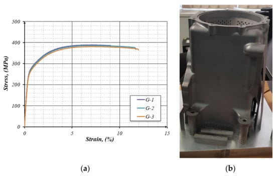
Figure 11.
The strain-stress curves of three synthesized samples from the AlSi10Mg alloy (a); prototype of a GTE gearbox housing, made from AlSi10Mg alloy powder (b).
The combined use of the SLM method and the finite element method has proven effective in reducing the mass of the gearbox housing. As a result, it was possible to reduce the weight of the product by 15%, and the mechanical properties of the product exceeded those obtained by casting [26,27].
7. Conclusions
Modification of the 3D model of housing structure made from aluminum alloy was carried out, which allowed for the reduction in the initial mass by 15%. The obtained strain-stress characteristics of the new housing correspond to the strength standards for aviation equipment.
Based on the metallographic analysis, the entrance control of the selected AlSi10Mg alloy powder was carried out; the results showed that 97% of the powder particles have a spherical shape with a size of 15–45 μm. The chemical composition of the powder complies with the requirements of DIN EN 1676-1996.
The Peclet optimization criterion for right selection of the technological regimes (modes) is proposed and justified, which characterizes the rate of introduction of laser energy in relation to the rate of its dissipation in the process during laser operation.
By simulating the process of layer-by-layer synthesis, preliminary values of the SSS and temperature field accompanying virtual printing were obtained, which allows for the forecasting of warping prior to real 3D printing.
The proposed optimized technological chain was confirmed by a successfully manufactured part on the ProX320 DMP and can be used for the manufacture of aviation products.
The question of the technological process certification needs to be subsequently discussed, because it represents the snowball or accumulated research results not statistically described yet. Various international organizations, including DVNGL [28,29], are involved in the certification of parts manufactured by additive technology methods.
Through simulation, the information of the maximal expected residual stresses could be provided for further optimization steps regarding the technological parameters. In a real test, this kind of information is usually obtained in X-ray testing methods with further recalculation of the X-ray elastic constants and is rather time consuming for serial production. The validation of the numerical models without verification with the as-printed results is not possible without numerous printing-simulating comparisons due to the lack of the practical information. Moreover, the question of the fully trustable simulation results alone is the sophisticate issue of the future. With artificial intelligence used to find the best combination of the technological properties based on the statistical results, these could be areas of future research.
Author Contributions
Conceptualization, L.M. and V.I.; methodology, L.S.; numerical simulation, M.P. and D.P.; validation, S.G.; metallographical and granulometric analysis, O.K.-K. and D.V. All authors have read and agreed to the published version of the manuscript.
Funding
This research is funded by the Ministry of Science and Higher Education of the Russian Federation as part of the World-class Research Center program: Advanced Digital Technologies (Contract no. 075-15-2020-903 dated 16 December 2020).
Institutional Review Board Statement
Not applicable.
Informed Consent Statement
Not applicable.
Data Availability Statement
Data sharing is not applicable.
Conflicts of Interest
The authors declare no conflict of interest. The funders had no role in the design of the study; in the collection, analyses, or interpretation of data; in the writing of the manuscript, or in the decision to publish the results.
References
- Brandt, M.; Sun, S.J.; Leary, M.; Feih, S.; Elambasseril, J.; Liu, Q.C. High-Value SLM Aerospace Components: From Design to Manufacture. Adv. Mater. Res. 2013, 633, 135–147. [Google Scholar] [CrossRef]
- Stolt, R.; Elgh, F.; Heikkinen, T. Design and Evaluation of Aerospace Components for SLM. In Transdisciplinary Engineering for Complex Socio-Technical Systems; IOS Press: Amsterdam, The Netherlands, 2019; Volume 10, pp. 157–166. [Google Scholar] [CrossRef]
- Kurzynowski, T.; Pawlak, A.; Smolina, I. The potential of SLM technology for processing magnesium alloys in aerospace industry. Arch. Civ. Mech. Eng. 2020, 20, 1–13. [Google Scholar] [CrossRef] [Green Version]
- Seabra, M.; Azevedo, J.; Araújo, A.; Reis, L.; Pinto, E.; Alves, N.; Santos, R.; Mortágua, J.P. Selective laser melting (SLM) and topology optimization for lighter aerospace componentes. Procedia Struct. Integr. 2016, 1, 289–296. [Google Scholar] [CrossRef] [Green Version]
- Barroqueiro, B.; Andrade-Campos, A.; Valente, R.; Neto, V. Metal Additive Manufacturing Cycle in Aerospace Industry: A Comprehensive Review. J. Manuf. Mater. Process. 2019, 3, 52. [Google Scholar] [CrossRef] [Green Version]
- Yusuf, S.M.; Cutler, S.; Gao, N. Review: The Impact of Metal Additive Manufacturing on the Aerospace Industry. Metals 2019, 9, 1286. [Google Scholar] [CrossRef] [Green Version]
- Uriondo, A.; Esperon-Miguez, M.; Perinpanayagam, S. The present and future of additive manufacturing in the aerospace sector: A review of important aspects. Proc. Inst. Mech. Eng. Part G J. Aerosp. Eng. 2015, 229, 2132–2147. [Google Scholar] [CrossRef]
- Vasiliev, B.E.; Salnikov, A.V.; Magerramova, L.A.; Isakov, V.V.; Semenov, A.V.; Shadrin, D.V.; Popov, A.A. Development of hollow disks for reducing the mass of promising engines. In Strength and Reliability of Gas Turbine Engines; Nozhnitskiy, Y.A., Ed.; CIAM: Moscow, Russia, 2020; pp. 157–165. [Google Scholar]
- Salwan, G.K.; Subbarao, R.; Mondal, S. Comparison and selection of suitable materials applicable for gas turbine blades. Mater. Today Proc. 2021, 46, 8864–8870. [Google Scholar] [CrossRef]
- Gibson, I.; Rosen, D.; Stucker, B.; Khorasani, M. Additive Manufacturing Technologies, 3rd ed.; Springer: Cham, Switzerland, 2021; p. 698. [Google Scholar] [CrossRef]
- Zhang, J.; Song, B.; Wei, Q.; Bourell, D.; Shi, Y. A review of selective laser melting of aluminum alloys: Processing, microstructure, property and developing trends. J. Mater. Sci. Technol. 2018, 35, 270–284. [Google Scholar] [CrossRef]
- Buchbinder, D.; Schleifenbaum, J.H.; Heidrich, S.; Meiners, W.; Bültmann, J. High Power Selective Laser Melting (HP SLM) of Aluminum Parts. Phys. Procedia 2011, 12, 271–278. [Google Scholar] [CrossRef]
- Olakanmi, E.O.; Cochrane, R.; Dalgarno, K. A review on selective laser sintering/melting (SLS/SLM) of aluminium alloy powders: Processing, microstructure, and properties. Prog. Mater. Sci. 2015, 74, 401–477. [Google Scholar] [CrossRef]
- Ponnusamy, P.; Rahman Rashid, R.A.; Masood, S.H.; Ruan, D.; Palanisamy, S. Mechanical Properties of SLM-Printed Aluminium Alloys: A Review. Materials 2020, 13, 4301. [Google Scholar] [CrossRef] [PubMed]
- Morgunov, Y.A.; Saushkin, B.P. Additive technologies for aerospace engineering. Addit. Technol. 2016, 1, 30–38. [Google Scholar]
- Tickoo, S. ANSYS Workbench 2019 R2: A Tutorial Approach, 3rd ed.; CADCIM Technologies: Schererville, IN, USA, 2019; p. 416. [Google Scholar]
- Rudsky, A.I. (Ed.) Metal Powders of Aluminum, Magnesium, Titanium and Silicon. Consumer Properties and Applications; Publishing House of the Polytechnic University: Saint Petersburg, Russia, 2012; p. 356. [Google Scholar]
- Andrianov, I.V.; Barantsev, R.G.; Manevich, L.I. Asymptotic Mathematics and Synergetics: The Path to Holistic Simplicity; Unitorial USSR: Moscow, Russia, 2004; p. 304. [Google Scholar]
- Rykalin, N.N.; Uglov, A.A.; Zuev, I.V.; Kokora, A.N. Laser and Electron-Beam Processing of Materials; Mashinostroenie: Moscow, Russia, 1985; p. 496. [Google Scholar]
- Ankudinov, V.E.; Krivilev, M.D. Theoretical Analysis of the Dependence of Thermophysical Characteristics on Porosity. Bull. Udmurt Univ. Phys. Chem. 2012, 4, 3–8. [Google Scholar]
- Dynin, N.; Zavodov, A.; Oglodkov, M.; Khasikov, D. The influence of process parameters of selective laser melting on the structure of aluminum alloy Al–Si–Mg system. All-Russian scientific research institute of aviation materials. Proc. VIAM 2017. [Google Scholar] [CrossRef]
- Altair University. Available online: https://altairuniversity.com/inspire-3dprint-2/ (accessed on 1 December 2021).
- Prashanth, K.; Eckert, J. Formation of metastable cellular microstructures in selective laser melted alloys. J. Alloy. Compd. 2017, 707, 27–34. [Google Scholar] [CrossRef]
- Raza, T.; Andersson, J.; Svensson, L.-E. Varestraint Testing of Selective Laser Additive Manufactured Alloy 718—Influence of Grain Orientation. Metals 2019, 9, 1113. [Google Scholar] [CrossRef] [Green Version]
- Kang, M.; Han, H.N.; Kim, C. Microstructure and Solidification Crack Susceptibility of Al 6014 Molten Alloy Subjected to a Spatially Oscillated Laser Beam. Materials 2018, 11, 648. [Google Scholar] [CrossRef] [PubMed] [Green Version]
- Ghiaasiaan, R.; Amirkhiz, B.S.; Shankar, S. Quantitative metallography of precipitating and secondary phases after strengthening treatment of net shaped casting of Al-Zn-Mg-Cu (7000) alloys. Mater. Sci. Eng. A 2017, 698, 206–217. [Google Scholar] [CrossRef]
- Zhang, H.; Wang, Y.; Wang, J.; Ni, D.; Wang, D.; Xiao, B.; Ma, Z. Achieving superior mechanical properties of selective laser melted AlSi10Mg via direct aging treatment. J. Mater. Sci. Technol. 2021, 108, 226–235. [Google Scholar] [CrossRef]
- DNVGL-CG-0197 Additive manufacturing—Qualification and certification process for materials and components. Available online: https://rules.dnv.com/docs/pdf/DNV/CG/2017-11/DNVGL-CG-0197.pdf (accessed on 1 December 2021).
- DNVGL-CP-0267 Additive Manufacturing. Available online: https://turkubusinessregion.com/wp-content/uploads/2019/11/DNVGL-CP-0267.pdf (accessed on 1 December 2021).
Publisher’s Note: MDPI stays neutral with regard to jurisdictional claims in published maps and institutional affiliations. |
© 2021 by the authors. Licensee MDPI, Basel, Switzerland. This article is an open access article distributed under the terms and conditions of the Creative Commons Attribution (CC BY) license (https://creativecommons.org/licenses/by/4.0/).