Article

Explicit Analysis of Sheet Metal Forming Processes Using Solid-Shell Elements

1
Hubei Provincial Engineering Research Center of Industrial Detonator Intelligent Assembly, Wuhan Textile University, Wuhan 430073, China
2
State Key Laboratory of Materials Processing and Die & Mould Technology, School of Materials Science and Engineering, Huazhong University of Science and Technology, Wuhan 430074, China
*
Author to whom correspondence should be addressed.
Metals 2022, 12(1), 52; https://doi.org/10.3390/met12010052
Submission received: 16 November 2021 / Revised: 10 December 2021 / Accepted: 20 December 2021 / Published: 27 December 2021
(This article belongs to the Special Issue Plastic Forming, Microstructure, and Property Optimization of Metals)

Abstract

:
To simulate sheet metal forming processes precisely, an in-house dynamic explicit code was developed to apply a new solid-shell element to sheet metal forming analyses, with a corotational coordinate system utilized to simplify the nonlinearity and to integrate the element with anisotropic constitutive laws. The enhancing parameter of the solid-shell element, implemented to circumvent the volumetric and thickness locking phenomena, was condensed into an explicit form. To avoid the rank deficiency, a modified physical stabilization involving the B-bar method and reconstruction of transverse shear components was adopted. For computational efficiency of the solid-shell element in numerical applications, an adaptive mesh subdivision scheme was developed, with element geometry and contact condition taken as subdivision criteria. To accurately capture the anisotropic behavior of sheet metals, material models with three different anisotropic yield functions were incorporated. Several numerical examples were carried out to validate the accuracy of the proposed element and the efficiency of the adaptive mesh subdivision.

1. Introduction

Recently, solid-shell elements have been a focus of research on modeling thin-walled structures [1,2]. As compared with shell elements which have been widely used for several decades, solid-shell elements are more suitable for double-sided contact situations such as sheet metal forming due to the existence of nodes at the upper and lower surfaces. In addition, without nodal rotational degrees of freedom, the kinetic and geometric descriptions of solid-shell elements are simpler than the descriptions of shell elements. A further advantage is that general 3D constitutive models can be used together with solid-shell elements, and in this way, the thickness variation can be precisely described, which makes solid-shell elements highly desirable when a workpiece with varying or large thickness is analyzed.
However, solid-shell elements have been plagued by various locking problems, and therefore the elements provide poor results. For example, when dealing with nearly incompressible situations, i.e., Poisson ratio approaching 0.5, such as rubber-like materials and metal plasticity, the artificial constraint at integration points may lead to volumetric locking. Another well-known locking problem associated with Poisson ratio is known as thickness locking or Poisson locking. It usually happens in out-of-plane bending analyses in which the displacement is assumed to vary linearly along the thickness direction, and as a result, a constant strain field along the thickness direction is obtained. Nevertheless, because the Poisson ratio is not equal to zero, the coupling between the normal thickness strain and the in-plane strains makes the normal thickness strain vary linearly in the thickness direction. In bending deformations of shell-type structures, transverse shear locking is also a severe problem, which appears when the element thickness is extremely small. Finally, in modeling curved structures with solid-shell elements, trapezoidal locking, also named as curvature locking, may take place when the element edges in the thickness direction are not perpendicular to the element mid-surface.
There have been significant efforts made to solve the abovementioned locking problems, among which, reduced integration and selective reduced integration are commonly adopted to treat volumetric locking and transverse shear locking [3]. Nevertheless, due to the rank deficiency caused by reduced integration, some stabilization procedures are necessary to avoid the appearance of hourglass modes. The enhanced assumed strain (EAS) method, which was proposed by Simo and Rifai [4], has been widely used in many studies to deal with volumetric locking, thickness locking, transverse shear locking, etc. For example, in a study by Su et al. [5], an in-plane reduced integration solid-shell element was proposed, with seven internal parameters used to enhance the strain field. In addition, in the solid-shell element presented by Li et al. [6], six internal parameters were adopted to attenuate transverse shear locking, with one other parameter used for volumetric and thickness locking. Although the EAS method is attractive for dealing with various locking, the extra internal parameters introduced by this approach will inevitably lead to an increase in numerical computations. To overcome the computational inefficiency of the EAS method, there is a need to introduce as few internal parameters as possible. As compared with the EAS method, the assumed natural strain (ANS) method is considered to be a more efficient technique to treat transverse shear and trapezoidal locking. Therefore, numerous solid-shell elements have been developed by combining the EAS and ANS such as the work of Mostafa et al. [7,8], Schwarze et al. [9], Cardoso et al. [10], and Norachan et al. [11].
Even though many proposed solid-shell elements show excellent performance in classical thin-walled tests, there are fewer applications of solid-shell element in practical engineering examples such as sheet metal forming as compared with shell elements. Via solid-shell elements, Schwarze et al. [12,13] and Parente et al. [14] analyzed the S-rail forming problem and the deep drawing of a cylindrical cup with anisotropy. In Schwarze et al.’s study [12], the deep drawing of a square cup was also simulated. In a study conducted by Wang et al. [15], several typical benchmark problems including a single point incremental sheet metal forming and spring back of a U-shaped component were employed to assess the capability of their proposed solid-shell element in sheet metal forming. The behavior of a solid-shell element in magnetic pulse forming was investigated by Mahmoud et al. [16]. Additionally, a solid-shell element was incorporated into an in-house program by Li et al. [6] to simulate the roll forming of a U-channel component.
The underdevelopment of solid-shell elements in the field of sheet metal forming may result from the technology adopted in the element formulation. As claimed in [17], there are only a few contributions using EAS in combination with explicit time integration. The EAS is based on the introduction of additional degrees of freedom at the element level, which can be condensed using local equation calculation and leads to exactly accurate element formulations in the context of implicit time integration methods. However, the application of EAS in an explicit framework will lead to an increase in the computational effort, especially in elements with many EAS parameters. As compared with implicit time integration schemes, explicit time integration schemes are more suitable for complex examples involving material nonlinearity, geometric nonlinearity, and changeable contact constraints between tools and workpiece. Thus, to investigate the application of solid-shell element in an explicit framework, the effect of the EAS to computational efficiency should be considered.
Computational effort of an explicit simulation is directly proportional to the number of mesh nodes. To decrease the total node number and to improve the computational efficiency dramatically, an adaptive meshing method for shell elements has been widely used in some well-known finite element analysis software for sheet metal forming such as Dynaform (ETA) [18] and Autoform (AutoForm Engineering GmbH, Pfäffikon, Switzerland) [19]. Nevertheless, this method has not been extensively studied in the field of solid-shell element. In a study by Xie et al. [20], a curvature-based mesh subdivision was proposed to avoid the non-physical interpenetration of element surfaces in fabric drape simulations. In addition, in the literature published by Sena et al. [21], an adaptive remeshing method developed for shell elements was applied to single point incremental forming simulations with a solid-shell element.
In our previous study [22], a solid-shell element was proposed for geometrically linear problems. To investigate the applicability of the proposed element in sheet metal forming analyses, an explicit in-house code with the nonlinear formulation of the element is developed in this study. The remainder of this paper is organized as follows: The solid-shell formulation is described in Section 2. After a brief introduction of the dynamic explicit algorithm in Section 3, an adaptive mesh subdivision scheme for the solid-shell element is proposed in Section 4. For the sake of sheet metal forming simulation with anisotropy, material models based on three yield functions, i.e., Hill48 [23], Yld91 [24], and Yld2004-18p [25], are summarized in Section 5. Finally, several numerical examples are presented to verify the accuracy and efficiency of the proposed element in sheet metal forming.

2. Solid-Shell Formulation

2.1. Geometrics and Kinematic

The isoparametric eight-node hexahedral solid-shell is shown in Figure 1. With ξ, η, and ζ representing the natural coordinates, only one integration point is used in the ξη-plane, and multiple integration points distribute along the ζ-axis. Via this special integration scheme, the element can accurately describe the stress variation in the thickness direction.
Each node of the element has three translational degrees of freedom and no rotational degree of freedom. The position vector x = { x , y , z } T and displacement vector u = { u , v , w } T at any point of the isoparametric domain can be obtained by the following interpolation functions:
x = i = 1 8 N i ( ξ , η , ζ ) x i = N c   and   u = i = 1 8 N i ( ξ , η , ζ ) u i = N d
where N = N 1 I 3 N 2 I 3 N 8 I 3 with N i ( ξ , η , ζ ) = 1 8 ( 1 + ξ i ξ ) ( 1 + η i η ) ( 1 + ζ i ζ ) denote the trilinear shape function at node I, c is the nodal coordinate vector, and d is the nodal displacement vector.
Considering the nonorthogonality of the natural frame, a corotational coordinate system is established at the element centroid to simplify the geometric and material nonlinearities and describe the strain and stress more objectively, with its unit vectors defined as:
r 1 = i = 1 8 ξ i x i                           r 1 = r 1 r 1 r 3 = r 1 × i = 1 8 η i x i         r 3 = r 3 r 3 r 2 = r 3 × r 1
Thus, the natural frame and the local coordinate system are related by:
t = r 1 r 2 r 3 T J 1
where J is the conventional Jacobian.
When a sheet metal forming analysis is conducted in the explicit framework, the deformation in a time step is small enough. Thus, the increment of the covariant strain ε ¯ u in time step n n + 1 can be computed from the displacement d n n + 1 by:
ε ¯ n n + 1 u = B ¯ u d n n + 1
The strain increment ε ˜ n n + 1 u in the corotational coordinate system is connected to the covariant strain increment ε ¯ n n + 1 u via ε ˜ n n + 1 u = T ε ¯ n n + 1 u , where the 6 × 6 transformation matrix T is expressed by the terms of matrix t, as follows:
T = [ t 11 t 11 t 12 t 12 t 13 t 13 t 11 t 12 t 12 t 13 t 13 t 11 t 21 t 21 t 22 t 22 t 23 t 23 t 21 t 22 t 22 t 23 t 23 t 21 t 31 t 31 t 32 t 32 t 33 t 33 t 31 t 32 t 32 t 33 t 33 t 31 2 t 11 t 21 2 t 12 t 22 2 t 13 t 23 t 11 t 22 + t 12 t 21 t 12 t 23 + t 13 t 22 t 13 t 21 + t 11 t 32 2 t 21 t 31 2 t 22 t 32 2 t 23 t 33 t 21 t 32 + J 22 t 31 t 22 t 33 + t 23 t 32 t 23 t 31 + t 21 t 33 2 t 31 t 11 2 t 32 t 12 2 t 33 t 13 t 31 t 12 + t 32 t 11 t 32 t 13 + t 33 t 12 t 33 t 11 + t 31 t 13 ]
Therefore, we have:
ε ˜ n n + 1 u = B ˜ u d n n + 1
with
B ˜ u = T B ¯ u

2.2. EAS Method

The EAS method is employed to overcome the volumetric and thickness locking problems of the solid-shell element, with the strain field enriched as follows:
ε ¯ n n + 1 = ε ¯ n n + 1 u + ε ¯ n n + 1 α
The increment of the enhancing strain can be written in a similar form with Equation (4), as:
ε ¯ n n + 1 α = B ¯ α α n n + 1
with B ¯ α = 0 0 ζ 0 0 0 T . For computational efficiency, only one internal variable is introduced in each element, i.e., α = { α 1 } . In this way, an enhancing strain field linear to ζ is added to the normal thickness component of ε ¯ n n + 1 u . With T 0 denoting the transformation matrix T evaluated at the element center ( ξ = 0 , η = 0 , ζ = 0 ) , ε ¯ n n + 1 α can be transformed into the corotational coordinate system by ε ˜ n n + 1 α = T 0 ε ¯ n n + 1 α .
The Veubeke–Hu–Washizu variational principle in large deformations can be expressed by:
δ Π ( d , ε ˜ , σ ^ ) = V e δ ε ˜ T σ ˜ d V + δ V e σ ^ T ( d ε ˜ ) d V + δ Π 1 δ Π 2 = 0
with
δ Π 1 = δ d T V e ρ N T N d V d ¨ = δ d T M d ¨ δ Π 2 = δ d T F ext
where ε ˜ denotes the assumed strain field, σ ˜ the assumed stress field, M the element mass matrix, and F ext the external nodal force vector. Due to the orthogonality condition as follows:
V e σ ^ T ( d ε ˜ ) d V = 0
the three-field variational function is simplified to:
δ Π ( d , ε ˜ ) = V e δ ε ˜ T σ ˜ d V + δ d T M d ¨ δ d T F ext = 0
Considering that the assumed strain ε ˜ consists of compatible and incompatible parts, we have:
δ d T ( F int + M d ¨ F ext ) = 0
δ α T F α int = 0
where F int = V e B ˜ u T σ ˜ d V and F α int = V e B ˜ α T σ ˜ d V are internal force vectors.
The compatible degrees of freedom d can be calculated by the central difference method, which is described in the next section. Concerning the internal degree of freedom α , the linearization of F α int ( d , α ) = 0 in the time step results in:
K ˜ ( n d , α k n ) ( α k + 1 n α k n ) = F α int ( n d , α k n )
where k denotes the iterative times of α n , α k = 0 n = α n 1 , and K ˜ ( n d , α k n ) = F α int α α n = α k n = V e B ˜ α T D ep B ˜ α d V α n = α k n . Due to the small time step of the explicit time integration, one single iteration is usually enough to obtain the correct result [17], and therefore the explicit form:
α n = α n 1 K ˜ 1 ( n d , α n 1 ) F α int ( n d , α n 1 )
can be adopted. With only one EAS parameter introduced in the element, K ˜ is essentially a scalar. Thus, no matrix inversion is involved in Equation (17), and α n can be worked out efficiently.

2.3. ANS Method

To avoid trapezoidal locking and transverse shear locking of the solid-shell element, the ANS method is employed in evaluations of the normal thickness term and the transverse shear terms of ε ¯ n n + 1 [22].

2.4. Hourglass Stabilization

Via Equation (7), we obtain B ˜ u in the following polynomial form:
B ˜ u = B ˜ 0 + B ˜ ζ ζ B ˜ + B ˜ ξ ξ + B ˜ η η + B ˜ η ζ η ζ + B ˜ ζ ξ ζ ξ B ˜ H
It should be noted that the term B ˜ ξ η is not considered to be in B ˜ H matrix since it is not needed in correcting the rank deficiency [26].
Locking problems must be controlled in the stabilization procedure. To overcome the volumetric locking phenomenon, the B-bar method [3,27] is utilized with the B ˜ H matrix split into deviatoric and dilatational parts, and the dilatational part is integrated at the element center, as follows:
B ˜ H ( ξ , η , ζ ) = B ˜ H dev ( ξ , η , ζ ) + B ˜ H dil ( 0 , 0 , 0 )
Both B ˜ H dev and B ˜ H dil can be expanded according to the expansion of B ˜ H in Equation (18). Without constant term in the expansion, the dilatational part is equal to zero. As a result, we have:
B ˜ H ( ξ , η , ζ ) = B ˜ H dev ( ξ , η , ζ )
It has been demonstrated that physical stabilization probably makes element behave overly stiff in bending-dominated situations, especially when the element width-to-thickness ratio tends to zero [3,10,28]. Aiming at improving the performance of the proposed element, the transverse shear terms of B ˜ H are reconstructed by:
B ˜ y z H = B ˜ y z η ζ η ζ + B ˜ y z ζ ξ ζ ξ B ˜ z x H = B ˜ z x η ζ η ζ + B ˜ z x ζ ξ ζ ξ
in which the linear parts contributing to the excessive hourglass stiffness are dropped out.
Via the B ˜ H matrix, the increment of the hourglass strain tensor can be obtained in the following way:
ε ˜ H n n + 1 = ε ˜ ξ n n + 1 ξ + ε ˜ η n n + 1 η + ε ˜ η ζ n n + 1 η ζ + ε ˜ ζ ξ n n + 1 ζ ξ
Accordingly, the hourglass stress tensor can be written in the form σ ˜ H n n + 1 = σ ˜ ξ n n + 1 ξ + σ ˜ η n n + 1 η + σ ˜ η ζ n n + 1 η ζ + σ ˜ ζ ξ n n + 1 ζ ξ with the terms in the polynomial calculated by:
σ ˜ ξ n n + 1 = E t E D e ε ˜ ξ n n + 1     σ ˜ η n n + 1 = E t E D e ε ˜ η n n + 1 σ ˜ η ζ n n + 1 = E t E D e ε ˜ η ζ n n + 1     σ ˜ ζ ξ n n + 1 = E t E D e ε ˜ ζ ξ n n + 1
where E represents the Young’s modulus, E t is the tangent modulus evaluating at the element center, and D e denotes the full 3D elastic constitutive model.
With the hourglass stabilization, the F int in Equation (14) can be rewritten as:
F int = V e B ˜ * T σ ˜ * d V F * + V e B ˜ H T σ ˜ H d V F H + V e B ˜ * T σ ˜ H d V = 0 + V e B ˜ H T σ ˜ * d V = 0 .
Since the hourglass stress tensor σ ˜ H is accumulated by σ ˜ H n + 1 = σ ˜ H n + σ ˜ H n n + 1 , it can also be expanded into linear and bilinear terms. By substituting σ ˜ H into F H = V e B ˜ H T σ ˜ H d V and considering the integrals
1 1 1 1 1 1 ξ 2 d ξ d η d ζ = 1 1 1 1 1 1 η 2 d ξ d η d ζ = 8 3 1 1 1 1 1 1 η 2 ξ 2 d ξ d η d ζ = 1 1 1 1 1 1 ζ 2 ξ 2 d ξ d η d ζ = 8 9
over the natural coordinates,
F H = 8 3 J 0 B ˜ ξ T σ ˜ ξ + 8 3 J 0 B ˜ η T σ ˜ η + 8 9 J 0 B ˜ η ζ T σ ˜ η ζ + 8 9 J 0 B ˜ ζ ξ T σ ˜ ζ ξ
can be analytically calculated, with J 0 being the determinant of the Jacobian matrix evaluated at the element center.

3. Central Difference Scheme and Time Step Estimation

According to Equations (14) and (24), the equilibrium equation for the dynamic analysis of sheet metal forming is expressed in the form:
Ass M d ¨ = Ass F ext Ass ( F * + F H )
with Ass denoting the assembly of matrixes or vectors in the global coordinate system. The mass matrix Ass M in Equation (27) is diagonalized. In this way, the assembled equilibrium equation can be uncoupled into:
m j d ¨ j = f j ext ( f j * + f j H )
leading to more convenient and economic computational process. By defining β = Δ t n / Δ t n 1 and substituting the following central difference equations:
d ˙ j n = β 1 + β d ˙ j n + 1 / 2 + 1 1 + β d ˙ j n 1 / 2 d ¨ j n = 2 ( 1 + β ) Δ t n 1 ( d ˙ j n + 1 / 2 d ˙ j n 1 / 2 )
into Equation (28), we have:
d ˙ j n + 1 / 2 = d ˙ j n 1 / 2 + ( 1 + β ) Δ t n 1 2 f j ext n ( f j * n + f j H n ) m j
Thus, the nodal velocity in time step n n + 1 is solved explicitly. With d j n + 1 = d j n + d ˙ j n + 1 / 2 Δ t n , the nodal displacement at t = t n + 1 can be obtained efficiently.
The central difference scheme is conditionally stable, and the time step Δ t should be less than a critical value Δ t cr , that is:
Δ t < Δ t cr = min l c .
where l represents the characteristic element size, and c is the wave propagation speed in this element [29]. Such a critical value is calculated individually for each element, and the minimum value is selected as the time step to guarantee the computational stability.

4. Adaptive Mesh Subdivision

With finer mesh, the material flowing behavior in complex sheet metal forming processes can be captured more accurately. However, a finer mesh will inevitability lead to higher computational cost. To attain an ideal balance between accuracy and efficiency, an adaptive mesh subdivision scheme is implemented for the proposed solid-shell element. In simulations with the adaptive mesh subdivision, the entire workpiece is originally discretized by coarse mesh. As the workpiece deforms, the element that meets a criterion will be subdivided automatically. Considering that in most analyses the critical time step is determined by the element thickness, the mesh subdivision is only carried out in the element plane, as shown in Figure 2. Thus, the element thickness is insensitive to the subdivision. For higher computational efficiency, a multilevel subdivision can be adopted.
Finer mesh is necessary in complex-deformation areas, and complex deformation may lead to element distortion. For this reason, two geometry-based criteria are employed in the adaptive mesh subdivision. Given that the subdivision level of the initial coarse element is 0, and the user-defined highest subdivision level is L max , an element with level L is subdivided if its maximum warping angle is greater than the critical value, that is:
ϑ = max ϑ A C , ϑ B D > ϑ κ c r ( κ = L < L max )
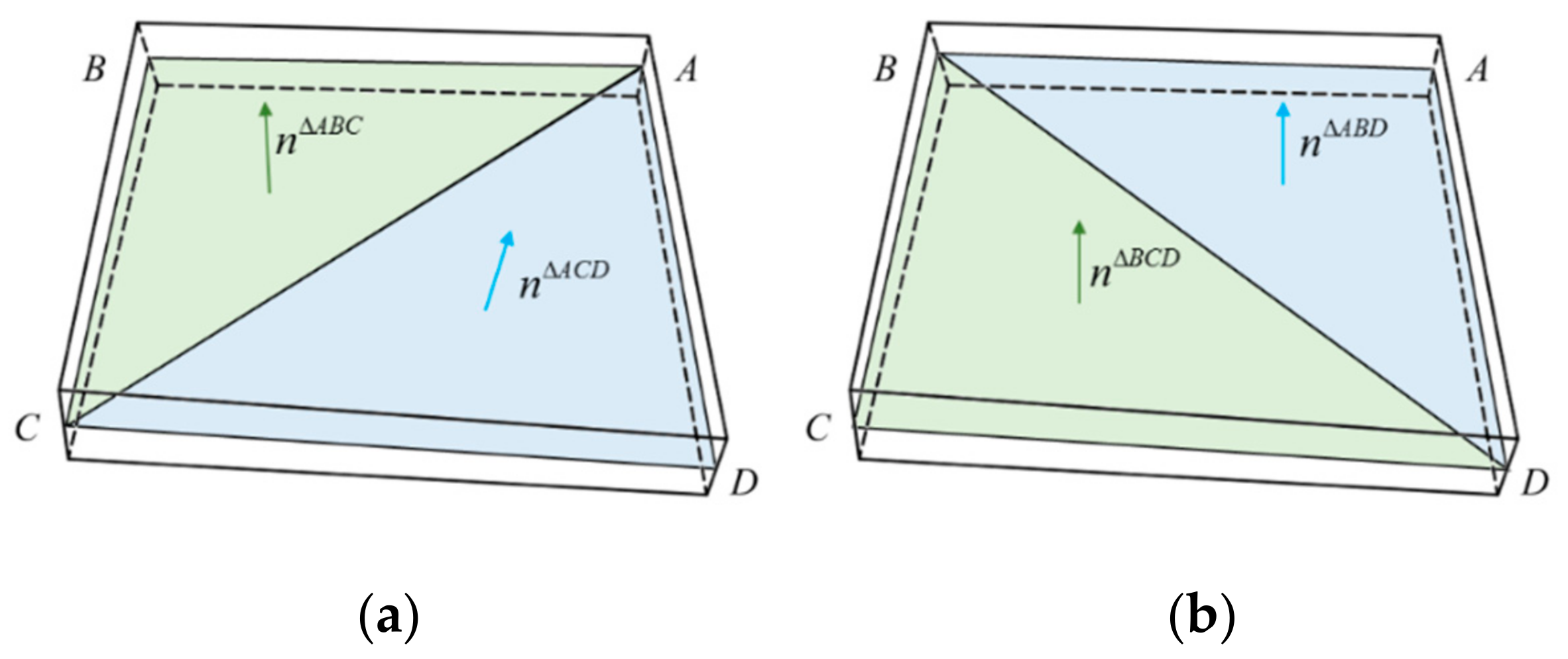
As shown in Figure 3, the warping angle ϑ A C is the angle between the triangle ABC and the triangle ACD, and the warping angle ϑ B D is the angle between the triangle ABD and the triangle BCD. The points A, B, C, and D indicate the midpoints of the four element edges in the thickness direction.
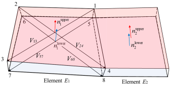
As exhibited in Figure 4, element E1 and E2 are adjacent, n 1 upper perpendicular to vectors V13 and V24 is defined as the normal vector of the upper surface of E1, and n 1 lower perpendicular to vectors V57 and V68 is defined as the normal vector of the lower surface of E1. Correspondingly, normal vectors n 2 upper and n 2 lower of element E2 can be obtained in the same way. The angle between n 1 upper and n 2 upper is denoted as θ upper , and the angle between n 1 lower and n 2 lower is θ lower . For two adjacent elements with subdivision level L 1 and L 2 , when the angle between them is greater than the critical value, that is:
θ = max θ upper , θ lower > θ κ c r ( κ = min ( L 1 , L 2 ) < L max )
the element with its subdivision level less than L max will be subdivided. θ upper and θ lower denote the angle at the upper and lower surface, respectively. The critical values ϑ κ c r and θ κ c r are two sets of preset parameters increasing with the subdivision level κ .
Despite the overall excellent performance, the geometry-based adaptive subdivision may give rise to nodal displacement oscillation. This is because, in the developed finite element code, the master-slave contact algorithm is adopted, in which the penetration of slave (workpiece) node into the master (tool) surface is not allowed. However, when a newly inserted node produced by the mesh subdivision is located on the back side of the tool surface, as shown in Figure 5, the initial penetration will bring about a force acting on the newly inserted node. If the initial penetration is large enough, the large and sudden force will probably lead to excessive dynamic oscillation. To avoid this problem, even though Equations (32) and (33) are not satisfied, the workpiece element is subdivided once a tool node penetrates it and the penetration distance is greater than the critical value, which is set as 3% of the workpiece thickness in this paper.
To ensure the simulation accuracy and robustness, the subdivision process is forbidden to produce adjacent elements with their subdivision level difference larger than 1. In addition, to get rid of gaps or overlaps between two adjacent elements with different levels, the newly inserted node is constrained at the middle of the common edge until the lower-level element is also subdivided.

5. Material Modeling

Yield functions are mathematical descriptions of the states of stresses that will cause yielding. A general form of yield functions is ϕ ( σ ) = ϕ ( σ i j ) = A σ ¯ m with σ ¯ being the equivalent stress. The plastic strain increment can be obtained by the associated flow rule:
d ε p = λ ϕ σ .
According to the work-equivalent principle σ T d ε p = σ ¯ d ε ¯ p , in which d ε ¯ p is the increment of equivalent plastic strain, and considering that σ ¯ is a first order homogenous function, i.e., σ ¯ = σ T σ ¯ σ , we obtain:
d ε p = σ ¯ σ d ε ¯ p
The combination of Equations (34) and (35) produces:
d ε ¯ p = λ d ϕ d   σ ¯ .
Furtherly, the substitution of Equation (36) into the consistency condition [30] as follows:
ϕ σ T d σ = d ϕ d ε ¯ p d ε ¯ p
leads to:
ϕ σ T d σ = λ d ϕ d   σ ¯ 2 d   σ ¯ d ε ¯ p = λ A m σ ¯ m 1 2 E p
where plastic modulus E p relates to Young’s modulus E and tangent modulus E t = d σ ¯ d ε ¯ in the form 1 E t = 1 E + 1 E p .
Based on the classical decomposition of strain into elastic and plastic components, the stress increment is achieved by:
d σ = D e d ε e = D e ( d ε d ε p )
Substituting Equation (34) into Equation (39) gives:
d σ = D e ( d ε λ ϕ σ )
By consolidating Equations (38) and (40), the plastic multiplier λ can be obtained as:
λ = ϕ σ T D e d ε ϕ σ T D e ϕ σ + A m   σ ¯ m 1 2 E p
Therefore, Equation (40) can be rewritten as d σ = D ep d ε with the elastoplastic tangent stiffness matrix taking the form:
D ep = D e D e ϕ σ ϕ σ T D e ϕ σ T D e ϕ σ + A m   σ ¯ m 1 2 E p
Since the strain increment in a time step is small enough, D ep is considered to be a constant matrix in a time step. As shown in Equation (42), the derivative of the yield function is necessary for the calculation of D ep . To describe the anisotropic behavior of metal sheets, many yield functions have been proposed. In the present study, three typical yield functions are programmed to work together with the proposed solid shell to analyze sheet metal forming processes.

5.1. Hill48 Yield Function

Being a well-accepted theory, the yield function by Hill [23] has been a popular choice, particularly for steels. The Hill48 yield function is defined as:
ϕ ( σ ) = F ¯ σ y y σ z z 2 + G ¯ σ z z σ x x 2 + H ¯ σ x x σ y y 2 + 2 L ¯ σ y z 2 + 2 M ¯ σ z x 2 + 2 N ¯ σ x y 2 = σ ¯ 2
The parameters F ¯ , G ¯ , H ¯ , L ¯ , M ¯ and N ¯ can be obtained via the Lankford coefficients r 0 , r 45 and r 90 according to the following form:
F ¯ = r 0 1 + r 0 r 90     G ¯ = 1 1 + r 0     H ¯ = r 0 1 + r 0     L ¯ = M ¯ = N ¯ = 1 + 2 r 45 r 0 + r 90 2 1 + r 0 r 90
The Hill48 yield function is easy to program since we can take the partial derivatives of Equation (43) in a straightforward way.

5.2. Yld91 Yield Function

The Yld91 yield function suggested by Barlat et al. [24] has also been widely used in sheet metal forming simulations, especially when aluminum sheets are employed. In Yld91, the orthotropic anisotropy is expressed via a matrix involving six independent anisotropy coefficients so that a new stress tensor s ˜ = C ¯ s = C ¯ T ¯ σ = L ¯ σ in the matrix form:
s ˜ = s ˜ x x s ˜ y y s ˜ z z s ˜ x y s ˜ y z s ˜ z x = 1 3 C 2 + C 3 C 3 C 2 0 0 0 C 3 C 1 + C 3 C 1 0 0 0 C 2 C 1 C 1 + C 2 0 0 0 0 0 0 3 C 4 0 0 0 0 0 0 3 C 5 0 0 0 0 0 0 3 C 6 σ x x σ y y σ z z σ x y σ y z σ z x
is introduced. Due to the transformation from the stress tensor σ to its deviator s , the yield function is pressure independent. The principal values of s ˜ are the roots of the characteristic equation:
P S ˜ k = S ˜ k 3 + 3 H 1 S ˜ k 2 + 3 H 2 S ˜ k + 2 H 3 = 0
with the associated 1st, 2nd, and 3rd invariants of s ˜ being:
H 1 = s ˜ x x + s ˜ y y + s ˜ z z / 3 H 2 = s ˜ x y 2 + s ˜ y z 2 + s ˜ z x 2 s ˜ x x s ˜ y y s ˜ y y s ˜ z z s ˜ z z s ˜ x x / 3 H 3 = 2 s ˜ y z s ˜ z x s ˜ x y + s ˜ x x s ˜ y y s ˜ z z s ˜ x x s ˜ y z 2 s ˜ y y s ˜ z x 2 s ˜ z z s ˜ x y 2 / 2
The three principal values S ˜ 1 , S ˜ 2 , and S ˜ 3 are used to express the yield function:
ϕ s = S ˜ 1 S ˜ 2 a + S ˜ 2 S ˜ 3 a + S ˜ 3 S ˜ 1 a = 2 σ ¯ a
where a is a constant coefficient being 6 and 8 for body-centered cubic (BCC) and face-centered cubic (FCC) materials, respectively.
By taking the partial derivatives of Equations (45)–(48), the derivative of the yield function, that is:
ϕ σ i j = ϕ S ˜ p S ˜ p H q H q s ˜ r s s ˜ r s σ i j
can be worked out and used for the calculation of the tangent stiffness matrix.

5.3. Yld2004-18pYield Function

To characterize the anisotropic behavior of metal sheets more precisely, Barlat et al. [25] developed another yield function denoted as Yld2004-18p:
ϕ s = i , j 1 , 3 S ˜ i S ˜ j a = 4 σ ¯ a
in which two linear transformations are involved, i.e., s ˜ = C ¯ s = C ¯ T ¯ σ and s ˜ = C ¯ s = C ¯ T ¯ σ , the linear transformations on the stress deviator being:
C ¯ = 0 c 12 c 13 0 0 0 c 21 0 c 23 0 0 0 c 31 c 32 0 0 0 0 0 0 0 c 44 0 0 0 0 0 0 c 55 0 0 0 0 0 0 c 66 ,   C ¯ = 0 c 12 c 13 0 0 0 c 21 0 c 23 0 0 0 c 31 c 32 0 0 0 0 0 0 0 c 44 0 0 0 0 0 0 c 55 0 0 0 0 0 0 c 66
As compared with Yld91, more anisotropic coefficients are introduced in this yield function. And obviously, Yld2004-18p reduced to Yld91 when the two linear transformations are the same. A little different from that in Yld91, the derivative in Yld2004-18p is written as follows:
ϕ σ i j = ϕ S ˜ p S ˜ p H q H q s ˜ r s s ˜ r s σ i j + ϕ S ˜ p S ˜ p H q H q s ˜ r s s ˜ r s σ i j

6. Numerical Examples

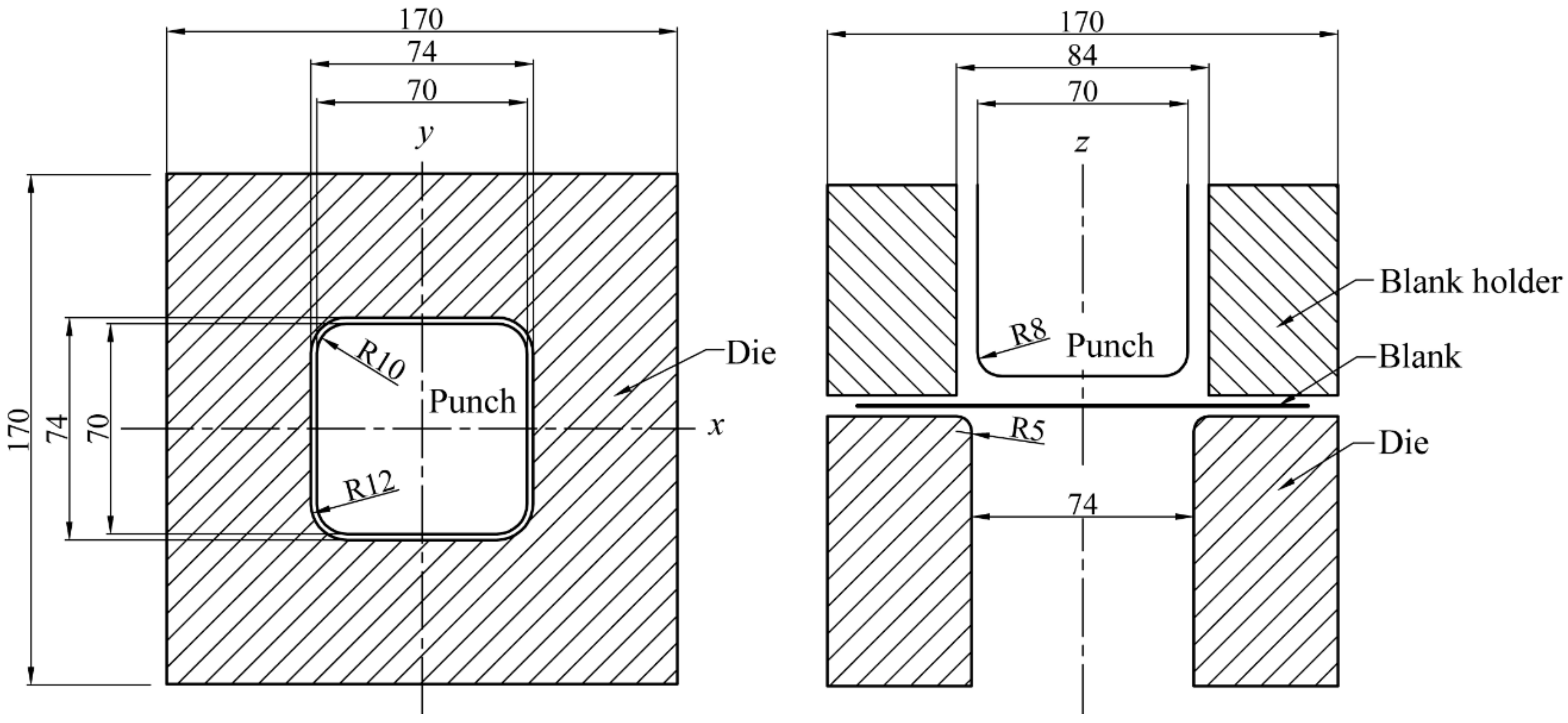
6.1. Deep Drawing of a Square Cup

The deep drawing of a square cup, a benchmark test of the Numisheet 1993 conference [31], is considered in this example. The geometry of the forming tools is sketched in Figure 6, in which a square blank of 150 × 150 × 0.78 mm is clamped by the blank holder and the die [32]. According to the data provided by the organizing committee, the friction coefficient between the blank and the tools is 0.144. Under a constant blank holder force of 16.6 kN, the blank is drawn into the die until the punch reaches its final stroke of 40 mm. A mild steel material is investigated, with Young’s modulus E = 206,000 MPa, Poisson ratio v = 0.3, mean yield stress σ s = 173.1 MPa, Lankford coefficients r 0 = 1.79, r 45 = 1.51, r 90 = 2.27, and mean hardening curve σ ¯ = 565.32 0.007117 + ε ¯ p 0.2589 MPa.
The proposed solid-shell element with five integration points along the thickness direction was adopted to analyze the drawing process. To validate the performance of the solid-shell element in adaptive mesh subdivision, two simulations were conducted for comparison. In the first simulation, the blank was initially discretized by 35 × 35 solid-shell elements with the adaptive mesh subdivision utilized during the forming process. The highest subdivision level was set as 1. And in the second simulation, the blank was discretized by 70 × 70 elements, with the element number kept constant during the simulation. Aiming at capturing the anisotropic behavior of the metal sheet, the Hill48 yield function was incorporated in the two simulations.
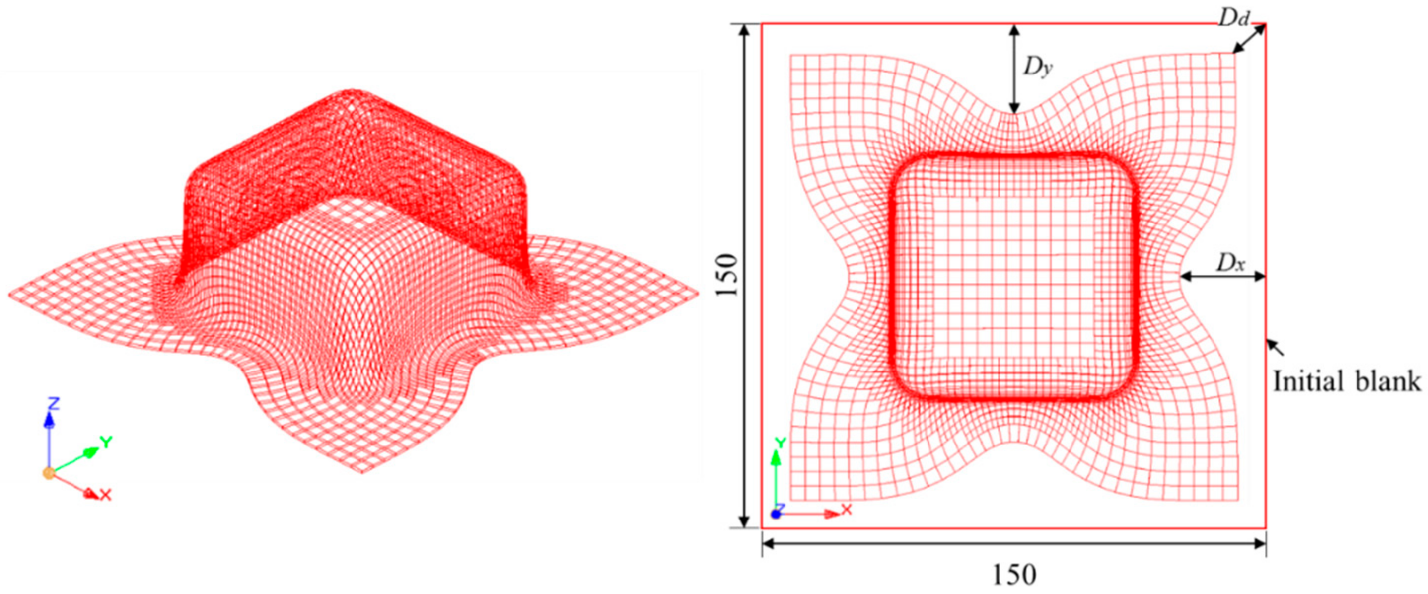
The time costs of these two simulations were 15 min and 10 min, respectively. It is indicated that the proposed adaptive mesh subdivision contributes to higher efficiency. The simulation results, for the first simulation, when the punch reaches its full stroke are shown in Figure 7, in which the element number of the square cup is 3397, much less than the one in the second simulation.
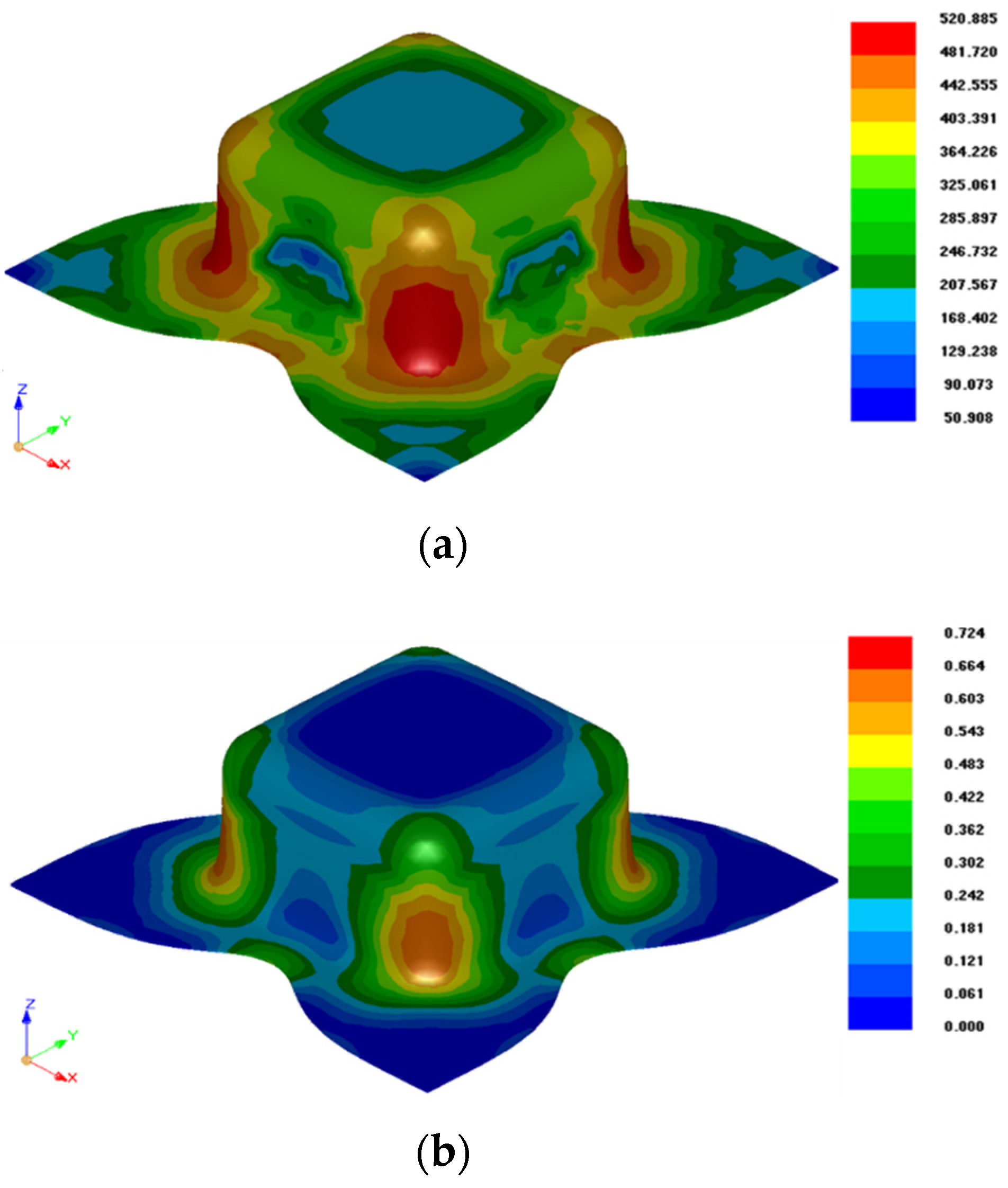
The forming results, including the stress and strain distributions at the final punch stroke, are given in Figure 8. We can find that the material experiences the highest stress in the areas contacting with the punch shoulders. This is because the material in these areas undergoes double-curved bending. Meanwhile, higher blank holder force makes it more difficult for the material in these areas to flow into the die. On the contrary, the material contacting the punch bottom experiences the minimum deformation, and the equivalent strain in this area is approximately zero.
In Figure 8, the draw-in length D x in the rolling direction, D y in the transverse direction, and D d in the diagonal direction are defined. To examine the accuracy of the simulations, the draw-in length in the two simulations were measured and listed in Table 1, and compared with experimental results [12]. We can find that even though there is a little difference between the results provided by the two simulations, all the simulation results lie between the minimum and maximum experimental results. This proves that the solid-shell element is suitable for sheet metal forming applications, and the computational stability has not been affected by the adaptive mesh subdivision.

6.2. Earing Prediction for a Cylindrical Cup

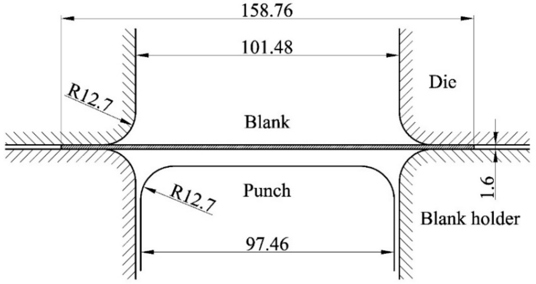
To examine the applicability of the constitutive models and evaluate the performance of the solid-shell element in anisotropic problems, a cylindrical cup drawing test was carried out with an AA2090-T3 sheet. The schematic view is shown in Figure 9 [34]. According to the experimental conditions, a constant blank holder force of 22.2 kN and a friction coefficient of 0.1 were employed [34].
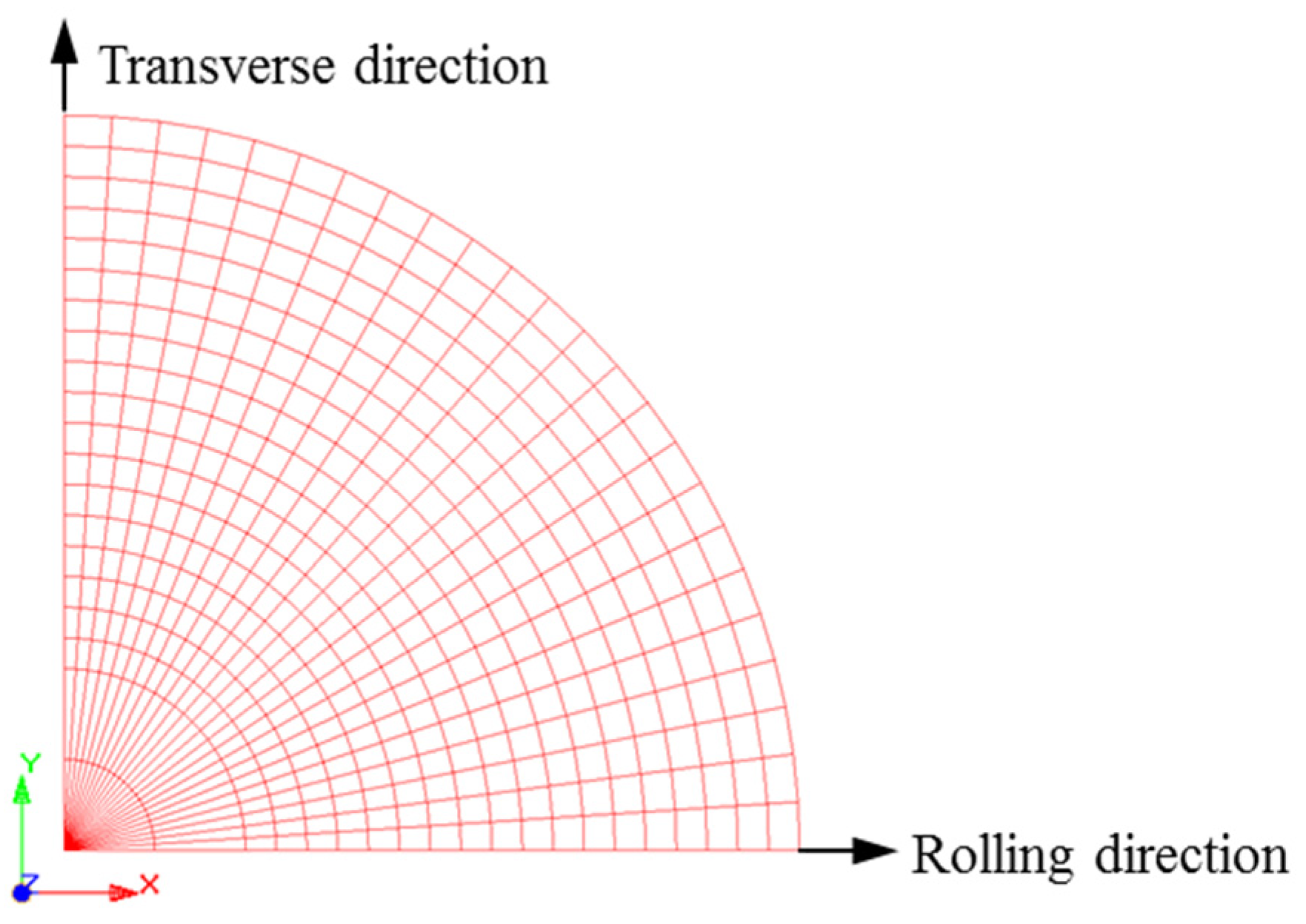
The geometric parameters of the blank are: initial thickness t 0 = 1.6 mm and diameter d = 158.76 mm. The circular blank was discretized by the proposed solid-shell element with five integration points across the thickness. A quarter of the finite element model is shown in Figure 10, in which the x-axis coincides with the rolling direction. The six-node prismatic elements in the center of the blank were considered to be special hexahedral elements involving coincident nodes. Simulations were conducted with three different yield functions, and the anisotropic coefficients are given in Table 2. The stress–strain curve of the material is σ ¯ = 646 0.025 + ε ¯ 0.227 MPa.
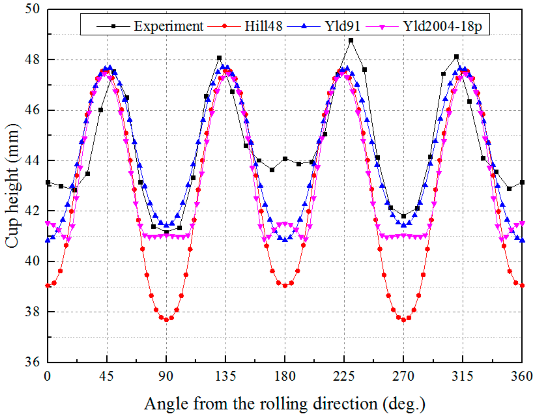
In Figure 11, the cup height is plotted versus the angle from the rolling direction. It can be observed that the material orthotropy is not completely satisfied in the experimental results, which may be caused by the inexact alignment between the center of the blank and the center of the tools during the drawing process [33]. By comparing the experimental data with the simulation results based on Hill48, Yld91, and Yld2004-18p, we can conclude that the proposed solid-shell element behaves well in all the simulations. A closer look shows that Hill48 exaggerates the earing phenomenon. The result calculated by Yld91 is in conformity with the experimental one, except that the small ears at 0° and 180° are not exactly predicted. From the viewpoint of earing prediction, the best agreement with the experimental result is obtained by Yld2004-18p.

6.3. Drawing of an Automobile Component

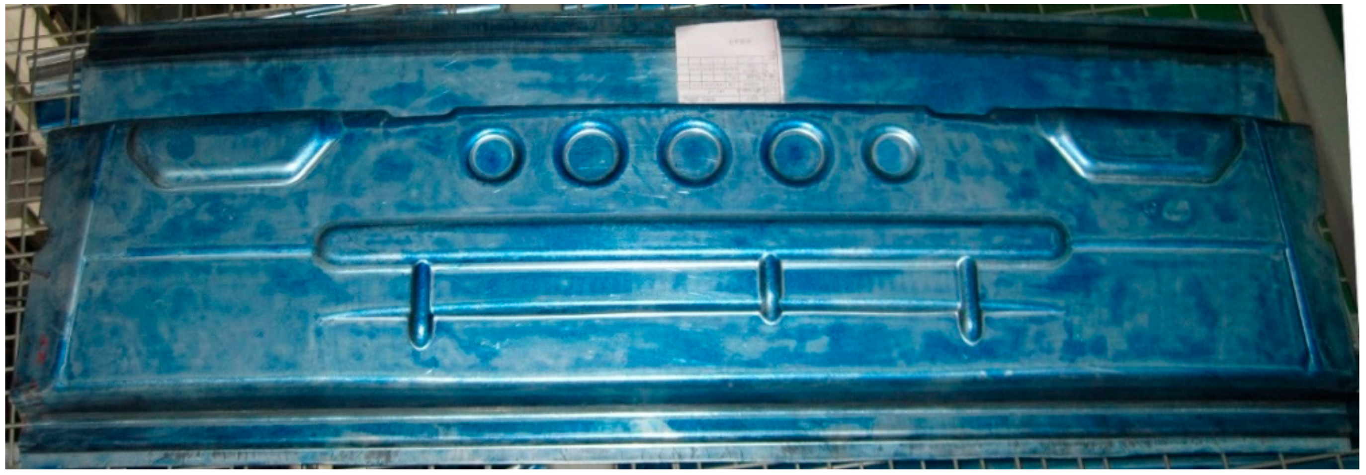
The drawing process of a complex automobile component is shown in Figure 12 and was analyzed to examine the accuracy and stability of the proposed element. The initial size of the blank is 270 × 550 × 1.5 mm. The finite element model of the drawing simulation is displayed in Figure 13, in which the blank is discretized by 22,246 solid-shell elements with five integration points in the thickness direction. At the beginning of the drawing process, the blank is located on the blank holder, and the die moves in the -z direction at a constant speed of 5 m/s. When the blank holder moves along with the die, the blank holder force increases linearly with the displacement. The initial blank holder force is 558.4 kN, and the final blank holder force at the full stroke is 764.9 kN. According to the many experiments conducted in the automobile enterprise, the lubrication condition between the blank and the tools in this example should yield a friction coefficient of 0.15.
The AA5754 material is used for the drawing process, with the x-axis in Figure 13 being the rolling direction. By uniaxial tensile tests in 0°, 45°, and 90° from the rolling direction, we obtained the following material parameters: Young’s modulus E = 70,000 MPa, Poisson ratio v = 0.3, hardening curve σ ¯ = 482.5 ( 0.007117 + ε ¯ p ) 0.324 MPa. The yield stresses σ 0 , σ 45 , and σ 90 obtained by the uniaxial tensile tests, along with the balanced biaxial yield stress σ b measured form a bulge test, were used to fit the coefficients C 1 ~ 4 of Yld91 for the AA5754 blank. The experimental data and the Yld91 coefficients are listed in Table 3.
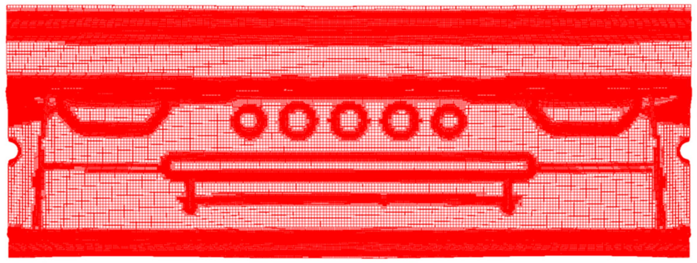
The adaptive mesh subdivision with the highest subdivision level being 2 was adopted. The simulation was conducted on an 8-core PC, and the computation time was 7.2 h. The finite element model of the final part is shown in Figure 14, in which the in-plane size of the smallest element is 1.41 mm, and the element number is 193,804. According to Figure 14, the adaptive mesh subdivision brings about finer mesh for some local areas, which makes the element number as low as possible.
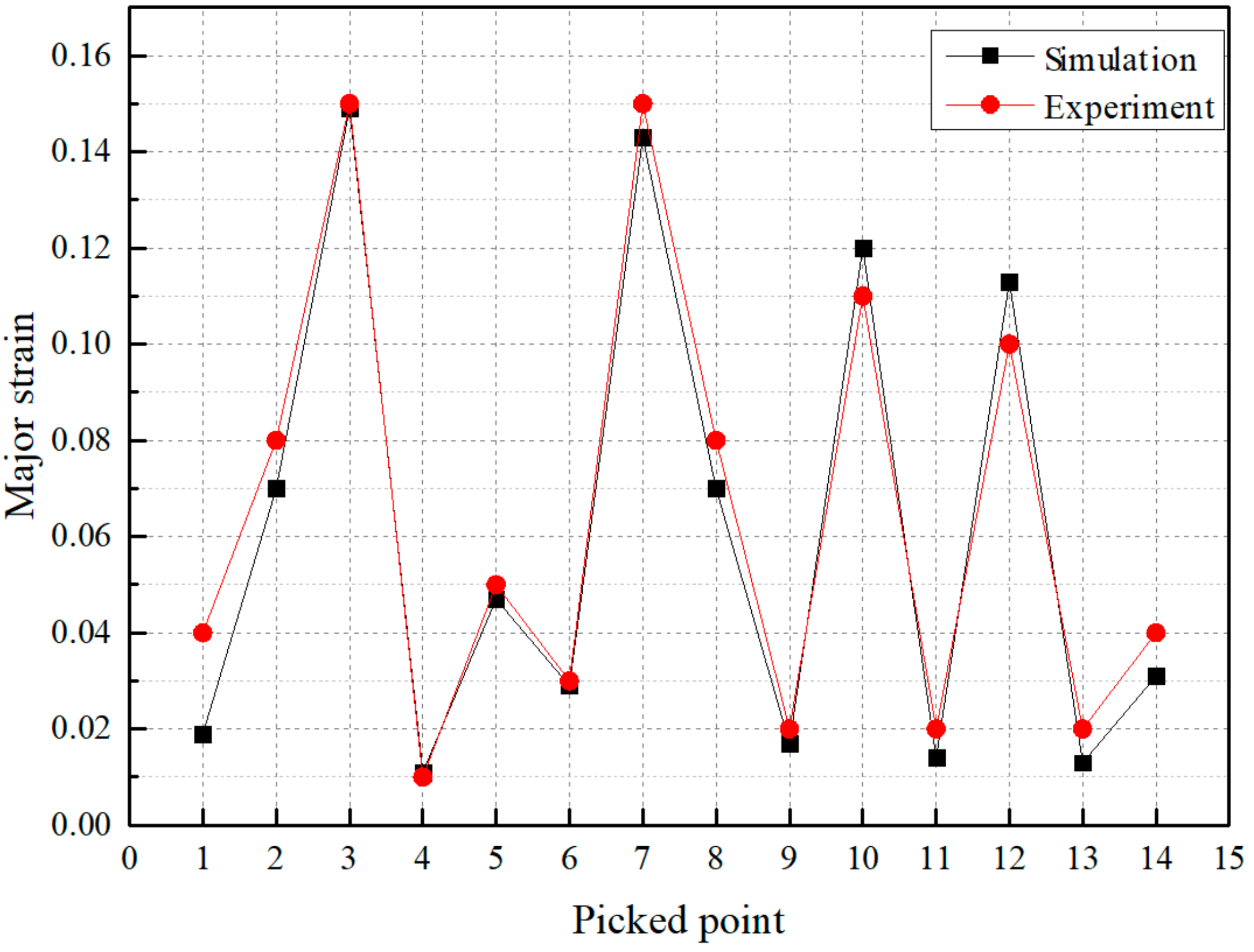
The major strain and the minor strain in the experiment were obtained by the optical strain measurement system ARGUS (GOM). Specifically, a hexagonal dot pattern was marked on the blank using electro-chemical etching before the drawing process. After the drawing process, the dots on the component were recorded by a handheld ARGUS camera (Argus, Michigan, MI, USA) from different viewing angles. Finally, the 2D coordinates of all the dots were mathematically derived and recalculated to 3D coordinates using photogrammetry principles. Thus, the strain values can be determined by evaluating the relative distance between the dots in combination with a local plane strain tensor computation. The measured results are given in Figure 15 and Figure 16 in comparison with the simulation results. It should be noted that the flange areas at the left and right ends are not shown in Figure 15b and Figure 16b, since the strain of these areas cannot be measured precisely by ARGUS. For this reason, the minimum values of the legends in the simulation and the experiment differ obviously. Some elements in Figure 15a and Figure 16a are picked out, with their strain values as compared with the measured ones in Figure 15b and Figure 16b. It can be found that the calculated strain distributions are overall in good conformity with the experimental results. The major strain values at the picked points in Figure 15 are plotted in Figure 17. It can be found that the maximum major strain is about 0.15, which exists at Point 3 and Point 7, indicating that when the die reaches its full stroke, large deformation takes place at these two areas since the material feeding resistance is considerable. Among the 14 points, only the errors at Points 1 and 13 are greater than 30%, and the errors at most of the points are less than 10%.

7. Conclusions

In this study, we applied a recently proposed solid-shell element to explicit analyses of sheet metal forming. In the deep drawing of a square cup, the solid-shell element achieves excellent agreement with the experimental draw-in results. It also proves that the proposed adaptive mesh subdivision can dramatically reduce the computational cost without obviously affecting simulation accuracy. Acting together with different constitutive laws involving Hill48, Yld91, and Yld2004-18p yield functions, a good correlation to the experimental results was obtained in predicting cup height. Among the three yield functions, Yld2004-18p demonstrated its superior performance in predicting the earing contour of the fully drawn cup. To further validate the accuracy in describing strain over the entire surface, the drawing process of an automobile component was computed, and again the accuracy of the proposed element and the robustness of the adaptive mesh subdivision were demonstrated. Altogether, the proposed solid-shell element is well suited for sheet metal forming simulations.

Author Contributions

Conceptualization, investigation, writing—original draft, writing—review and editing, and funding acquisition, Q.-M.L.; visualization, Z.-W.Y.; methodology, Y.-Q.L.; software, X.-F.T.; validation, W.J. and H.-J.L. All authors have read and agreed to the published version of the manuscript.

Funding

This work was financially supported by the National Natural Science Foundation of China (grant no. 51805181) and the State Key Laboratory of Materials Processing and Die & Mould Technology (grant no. P2022-023).

Institutional Review Board Statement

Not applicable.

Informed Consent Statement

Not applicable.

Data Availability Statement

Not applicable.

Conflicts of Interest

The authors declare no conflict of interest.

References

  1. Chalal, H.; Abed-Meraim, F. Simulation of structural applications and sheet metal forming processes based on quadratic solid–shell elements with explicit dynamic formulation. Int. J. Appl. Mech. 2019, 11, 1950082. [Google Scholar] [CrossRef]
  2. Antolin, P.; Kiendl, J.; Pingaro, M.; Reali, A. A simple and effective method based on strain projections to alleviate locking in isogeometric solid shells. Comput. Mech. 2020, 65, 1621–1631. [Google Scholar] [CrossRef] [Green Version]
  3. Alves De Sousa, R.J.; Cardoso, R.P.R.; Fontes Valente, R.A.; Yoon, J.; Grácio, J.J.; Natal Jorge, R.M. A new one-point quadrature enhanced assumed strain (EAS) solid-shell element with multiple integration points along thickness: Part I—geometrically linear applications. Int. J. Numer. Meth. Eng. 2005, 62, 952–977. [Google Scholar] [CrossRef]
  4. Simo, J.C.; Rifai, M.S. A class of mixed assumed strain methods and the method of incompatible modes. Int. J. Numer. Meth. Eng. 1990, 29, 1595–1638. [Google Scholar] [CrossRef]
  5. Su, Z.; Xue, P.; Tang, Y. An improved solid-shell element based on the computational condensation technique. Int. J. Mech. Sci. 2018, 141, 236–244. [Google Scholar] [CrossRef]
  6. Li, L.M.; Peng, Y.H.; Li, D.Y. A stabilized underintegrated enhanced assumed strain solid-shell element for geometrically nonlinear plate/shell analysis. Finite Elem. Anal. Des. 2011, 47, 511–518. [Google Scholar] [CrossRef]
  7. Mostafa, M.; Sivaselvan, M.V.; Felippa, C.A. A solid-shell corotational element based on ANDES, ANS and EAS for geometrically nonlinear structural analysis. Int. J. Numer. Meth. Eng. 2013, 95, 145–180. [Google Scholar] [CrossRef]
  8. Mostafa, M. An improved solid-shell element based on ANS and EAS concepts. Int. J. Numer. Meth. Eng. 2016, 108, 1362–1380. [Google Scholar] [CrossRef]
  9. Schwarze, M.; Reese, S. A reduced integration solid-shell finite element based on the EAS and the ANS concept—Geometrically linear problems. Int. J. Numer. Meth. Eng. 2009, 80, 1322–1355. [Google Scholar] [CrossRef]
  10. Cardoso, R.P.R.; Yoon, J.W.; Mahardika, M.; Choudhry, S.; Alves De Sousa, R.J.; Fontes Valente, R.A. Enhanced assumed strain (EAS) and assumed natural strain (ANS) methods for one-point quadrature solid-shell elements. Int. J. Numer. Meth. Eng. 2008, 75, 156–187. [Google Scholar] [CrossRef]
  11. Norachan, P.; Suthasupradit, S.; Kim, K. A co-rotational 8-node degenerated thin-walled element with assumed natural strain and enhanced assumed strain. Finite Elem. Anal. Des. 2012, 50, 70–85. [Google Scholar] [CrossRef]
  12. Schwarze, M.; Vladimirov, I.N.; Reese, S. Sheet metal forming and springback simulation by means of a new reduced integration solid-shell finite element technology. Comput. Method. Appl. Mech. Eng. 2011, 200, 454–476. [Google Scholar] [CrossRef]
  13. Schwarze, M.; Vladimirov, I.N.; Reese, S. A new continuum shell finite element for sheet metal forming applications. Int. J. Mater. Form. 2010, 3, 919–922. [Google Scholar] [CrossRef]
  14. Parente, M.P.L.; Fontes Valente, R.A.; Natal Jorge, R.M.; Cardoso, R.P.R.; Alves De Sousa, R.J. Sheet metal forming simulation using EAS solid-shell finite elements. Finite Elem. Anal. Des. 2006, 42, 1137–1149. [Google Scholar] [CrossRef]
  15. Wang, P.; Chalal, H.; Abed-Meraim, F. Quadratic solid–shell elements for nonlinear structural analysis and sheet metal forming simulation. Comput. Mech. 2017, 59, 161–186. [Google Scholar] [CrossRef] [Green Version]
  16. Mahmoud, M.; Bay, F.; Muñoz, D.P. An efficient multiphysics solid shell based finite element approach for modeling thin sheet metal forming processes. Finite Elem. Anal. Des. 2022, 198, 103645. [Google Scholar] [CrossRef]
  17. Mattern, S.; Schmied, C.; Schweizerhof, K. Highly efficient solid and solid-shell finite elements with mixed strain–displacement assumptions specifically set up for explicit dynamic simulations using symbolic programming. Comput. Struct. 2015, 154, 210–225. [Google Scholar] [CrossRef]
  18. Chen, T.C.; Hsu, C.M.; Wang, C.C. The deep drawing of a flanged square hole in thin stainless steel sheet. Metals 2021, 11, 1436. [Google Scholar] [CrossRef]
  19. Palmieri, M.E.; Lorusso, V.D.; Tricarico, L. Robust optimization and Kriging metamodeling of deep-drawing process to obtain a regulation curve of blank holder force. Metals 2021, 11, 319. [Google Scholar] [CrossRef]
  20. Xie, Q.; Sze, K.Y.; Zhou, Y.X. Drape simulation using solid-shell elements and adaptive mesh subdivision. Finite Elem. Anal. Des. 2015, 106, 85–102. [Google Scholar] [CrossRef] [Green Version]
  21. de Sena, J.I.V.; Guzmán, C.F.; Duchêne, L.; Habraken, A.M.; Behera, A.K.; Duflou, J.; Valente, R.A.F.; de Sousa, R.J.A. Simulation of a two-slope pyramid made by SPIF using an adaptive remeshing method with solid-shell finite element. Int. J. Mater. Form. 2016, 9, 383–394. [Google Scholar] [CrossRef] [Green Version]
  22. Li, Q.; Liu, Y.; Zhang, Z.; Zhong, W. A new reduced integration solid-shell element based on EAS and ANS with hourglass stabilization. Int. J. Numer. Meth. Eng. 2015, 104, 805–826. [Google Scholar] [CrossRef]
  23. Hill, R. A theory of the yielding and plastic flow of anisotropic metals. In Proceedings of the Royal Society of London. Series A, Mathematical and Physical Sciences; The Royal Society: London, UK, 1948; Volume 193, pp. 281–297. [Google Scholar]
  24. Barlat, F.; Lege, D.J.; Brem, J.C. A six-component yield function for anisotropic materials. Int. J. Plast. 1991, 7, 693–712. [Google Scholar] [CrossRef]
  25. Barlat, F.; Aretz, H.; Yoon, J.W.; Karabin, M.E.; Brem, J.C.; Dick, R.E. Linear transfomation-based anisotropic yield functions. Int. J. Plast. 2005, 21, 1009–1039. [Google Scholar] [CrossRef]
  26. Reese, S. A large deformation solid-shell concept based on reduced integration with hourglass stabilization. Int. J. Numer. Meth. Eng. 2007, 69, 1671–1716. [Google Scholar] [CrossRef]
  27. Recio, D.P.; Jorge, R.M.N.; Dinis, L.M.S. Locking and hourglass phenomena in an element-free Galerkin context: The B-bar method with stabilization and an enhanced strain method. Int. J. Numer. Meth. Eng. 2006, 68, 1329–1357. [Google Scholar] [CrossRef]
  28. Reese, S.; Rickelt, C. A model-adaptive hanging node concept based on a new non-linear solid-shell formulation. Comput. Methods Appl. Mech. Eng. 2007, 197, 61–79. [Google Scholar] [CrossRef]
  29. Zhu, J.Z.; Taylor, Z.; Zienkiewicz, O.C. The Finite Element Method: Its Basis and Fundamentals; Elsevier: Oxford, UK, 2013; p. 613. [Google Scholar]
  30. Dunne, F.; Petrinic, N. Introduction to Computational Plasticity; Oxford University Press: Demand, UK, 2005; pp. 20–23. [Google Scholar]
  31. Makinouchi, A.; Nakamachi, E.; Oñate, E.; Wagoner, R.H. (Eds.) Numisheet 1993. In Proceedings of the 2nd International Conference and Workshop on Numerical Simulation of 3D Sheet Forming Processes—Verification of Simulation with Experiment, Isehara, Japan, 31 August–2 September 1993. [Google Scholar]
  32. Danckert, J. Experimental investigation of a square-cup deep-drawing process. J. Mater. Process. Technol. 1995, 50, 375–384. [Google Scholar] [CrossRef]
  33. Yoon, J.; Barlat, F.; Dick, R.; Karabin, M. Prediction of six or eight ears in a drawn cup based on a new anisotropic yield function. Int. J. Plast. 2006, 22, 174–193. [Google Scholar] [CrossRef]
  34. Alves De Sousa, R.J.; Yoon, J.W.; Cardoso, R.P.R.; Fontes Valente, R.A.; Grácio, J.J. On the use of a reduced enhanced solid-shell (RESS) element for sheet forming simulations. Int. J. Plast. 2007, 23, 490–515. [Google Scholar] [CrossRef]
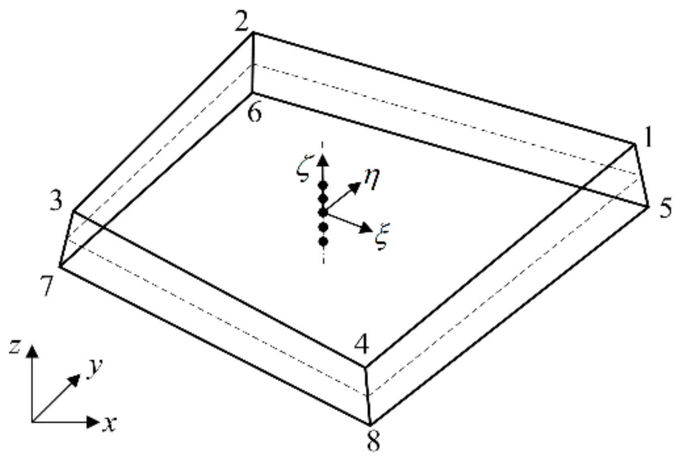
Figure 1. Solid-shell element with integration points. Adapted from Ref. [22] with permission from John Wiley and Sons (2021).
Metals 12 00052 g001
Figure 2. In-plane subdivision of the solid-shell element.
Metals 12 00052 g002
Figure 3. Definition of the warping angle. (a) ϑ A C is the angle between n Δ A B C and n Δ A C D (b) ϑ B D is the angle between n Δ A B D and n Δ B C D .
Metals 12 00052 g003
Figure 4. Definition of angle between adjacent elements.
Metals 12 00052 g004
Figure 5. Penetration of a newly inserted node into the tool surface.
Metals 12 00052 g005
Figure 6. Schematic view of the deep drawing of a square cup (units in mm).
Metals 12 00052 g006
Figure 7. Part mesh and definition of the draw-in length. Adapted from Ref. [33] with permission from Elsevier (2021).
Metals 12 00052 g007
Figure 8. Distributions of (a) equivalent stress (unit in MPa) and (b) equivalent strain obtained by simulation.
Metals 12 00052 g008
Figure 9. Schematic view of the deep drawing of a cylindrical cup (units in mm).
Metals 12 00052 g009
Figure 10. A quarter of the blank model.
Metals 12 00052 g010
Figure 11. Cup height profile: Experimental and simulation results.
Metals 12 00052 g011
Figure 12. Automobile component.
Metals 12 00052 g012
Figure 13. Finite element model for the drawing process of the automobile component.
Metals 12 00052 g013
Figure 14. Finite element model of the final part.
Metals 12 00052 g014
Figure 15. Results of the major strain obtained by (a) simulation and (b) experiment.
Metals 12 00052 g015
Figure 16. Results of the minor strain obtained by (a) simulation and (b) experiment.
Metals 12 00052 g016
Figure 17. Major strain values at the picked points in Figure 15.
Metals 12 00052 g017
Table 1. Draw-in results for comparison (units in mm).
D x D y D d
Min. experiment26.7526.7514.60
Max. experiment29.6029.5816.31
35 × 35 mesh with subdivision27.9327.7315.20
70 × 70 mesh29.2229.2116.02
Table 2. Yield function coefficients of AA2090-T3 [33]. Adapted from Ref. [33] with permission from Elsevier (2021).
Hill48 r-Values
r 0 r 45 r 90
0.21151.57690.6923
Yld91 Coefficients
C 1 C 2 C 3 C 4 C 5 C 6 a
1.06740.85591.12961.29701.00001.00008
Yld2004-18p Coefficients
c 12 c 13 c 21 c 23 c 31 c 32 c 44 c 55 c 66 a
−0.06980.93640.07911.00300.52471.36310.95431.02371.06908
c 12 c 13 c 21 c 23 c 31 c 32 c 44 c 55 c 66
0.98110.47670.57530.86681.1450−0.07921.40461.05161.1471
Table 3. Anisotropy coefficients of AA5754. Adapted from Ref. [33] with permission from Elsevier (2021).
Experimental Data (MPa)
σ 0 σ 45 σ 90 σ b
99.0100.5102.598.9
Yld91 coefficients
C 1 C 2 C 3 C 4 C 5 C 6 a
0.96691.03420.96480.97971.00001.00008
Publisher’s Note: MDPI stays neutral with regard to jurisdictional claims in published maps and institutional affiliations.