Article

Effects of Plasma-Chemical Composition on AISI 316L Surface Modification by Active Screen Nitrocarburizing Using Gaseous and Solid Carbon Precursors

1
Institute of Materials Engineering, Technische Universität Bergakademie Freiberg, Gustav-Zeuner-Str. 5, 09599 Freiberg, Germany
2
Leibniz Institute for Plasma Science and Technology (INP), Felix-Hausdorff-Str. 2, 17489 Greifswald, Germany
*
Author to whom correspondence should be addressed.
Metals 2021, 11(9), 1411; https://doi.org/10.3390/met11091411
Submission received: 30 July 2021 / Revised: 30 August 2021 / Accepted: 2 September 2021 / Published: 7 September 2021
(This article belongs to the Special Issue Active Screen Plasma Treatment)

Abstract

:
Low-temperature plasma nitrocarburizing treatments are applied to improve the surface properties of austenitic stainless steels by forming an expanded austenite layer without impairing the excellent corrosion resistance of the steel. Here, low-temperature active screen plasma nitrocarburizing (ASPNC) was investigated in an industrial-scale cold-wall reactor to compare the effects of two active screen materials: (i) a steel active screen with the addition of methane as a gaseous carbon-containing precursor and (ii) an active screen made of carbon-fibre-reinforced carbon (CFC) as a solid carbon precursor. By using both active screen materials, ASPNC treatments at variable plasma conditions were conducted using AISI 316L. Moreover, insight into the plasma-chemical composition of the H2-N2 plasma for both active screen materials was gained by laser absorption spectroscopy (LAS) combined with optical emission spectroscopy (OES). It was found that, in the case of a CFC active screen in a biased condition, the thickness of the nitrogen-expanded austenite layer increased, while the thickness of the carbon-expanded austenite layer decreased compared to the non-biased condition, in which the nitrogen- and carbon-expanded austenite layers had comparable thicknesses. Furthermore, the crucial role of biasing the workload to produce a thick and homogeneous expanded austenite layer by using a steel active screen was validated.

1. Introduction

Austenitic stainless steels are characterized by superior corrosion resistance and are therefore widely applied in different fields, such as the food, biomedical, and chemical processing industries [1]. However, in contact with abrasive particles under high-contact loads, their service lives are extremely limited due to their low surface hardness and poor wear resistance [2,3]. Plasma-assisted thermochemical diffusion treatment has drawn significant attention for its capacity to enhance the surface properties of stainless steels and its simple process implementation, low cost, and low environmental impact. Different plasma-assisted treatments, such as plasma nitriding (PN) [4,5], plasma carburizing (PC) [6,7], and plasma nitrocarburizing (PNC) [8,9], have been realized by introducing nitrogen- and/or carbon-containing precursor gases to the process atmosphere. Nevertheless, two main challenges for the thermochemical diffusion treatment of stainless steels can be pointed out: (i) the chromium oxide (Cr2O3) passive layer preventing nitrogen and carbon atoms from diffusing into the stainless steel, and (ii) the chromium nitride and/or chromium carbide precipitation at elevated treatment temperatures/times, which in turn negatively affect the corrosion resistance [10,11,12]. Previous studies have shown that the chromium oxide passive layer on the stainless steel surface can be removed from the component surface through high-energy ion bombardment, such as ion sputtering [13,14,15], as well as by etching with unsaturated hydrocarbons like HCN or C2H2 [16,17,18,19,20], which can be applied either before or during the thermochemical treatment. As a result of such surface activation, the nitrogen and/or carbon atoms can diffuse into the steel substrate and consequently the surface hardness and thus the wear resistance of stainless steel increase [21]. In addition, for stainless steels, low-temperature treatment based on the temperature–time stability curve of the treated material can be considered to avoid the precipitation of chromium nitride/carbide and the associated chromium depletion in the matrix, maintaining the corrosion resistance as good as that of untreated stainless steels [11,22]. Thus, a low-temperature PNC treatment (<460 °C) for austenitic stainless steels has been developed, where nitrogen and carbon atoms diffuse simultaneously into the de-passivated austenitic stainless steel surface [11,23]. This results in the formation of a dual-layer structure of supersaturated solid solution of nitrogen and carbon in the face-centred cubic (fcc) structure of austenite known as “expanded austenite”, which is free of chromium nitride/carbide precipitations. The expanded austenite layer generated by the simultaneous incorporation of nitrogen and carbon atoms consists of a near-surface nitrogen-expanded austenite layer (γN) and a subjacent carbon-expanded austenite (γC) layer [10,23].
A technological improvement in conventional plasma-assisted thermochemical treatment has been achieved by relocating the major part of the glow discharge from the workload to an additionally introduced cathodic meshed screen, the active screen (AS), which surrounds the entire workload to form an “afterglow” or a “post-discharge” condition for the treatment [24,25,26]. The AS plasma provides (i) the generation of process-relevant species from the precursor gases and (ii) an excellent radiation-controlled temperature homogeneity at the workload. It has also been shown that a weak bias discharge at the components’ surfaces is essential for industrial-scale reactors using an AS made of steel in order to achieve the desired treatment response [27,28]. Hence, plasma-assisted thermochemical treatments operating with an AS have two control parameters: (i) a relatively strong plasma power at the AS and (ii) a weak-bias plasma power at the workload. This is contrary to the conventional plasma-assisted treatments in which the entire plasma power dissipates at the workload. Therefore, the use of an AS for plasma-assisted treatment overcomes the limitations of conventional plasma-assisted treatments related to the high power density of the plasma applied to the workload, such as arcing, hollow cathodes, or inhomogeneous temperature distribution for loads consisting of mixed parts with different geometries [29,30]. Burlacov and co-workers [31] conducted a study on the AS technology for plasma nitrocarburizing (ASPNC) treatments in an industrial-scale cold-wall reactor using a steel AS. In their work, the proportion of gaseous carbon-containing precursor admixtures, such as CO2 or CH4, entering the H2-N2 feed gas controls the carburizing effect. However, performing the ASPNC treatment with gaseous carbon-containing precursors can lead to supersaturation of the process atmosphere [32], resulting in the formation of carbon soot on the surface of the components as well as cementite precipitation, which negatively affects the treatment result [33]. Recently, a novel plasma-assisted approach based on AS technology has been developed for ASPNC treatments that involves substituting the conventionally used steel AS with a carbon-fibre-reinforced carbon (CFC) AS that can be considered as a solid-state carbon precursor [34,35,36]. The use of a solid-state carbon precursor (CFC-AS) instead of a gaseous carbon-containing precursor (steel AS) for nitrocarburizing treatments affects the plasma-chemical composition and consequently influences the treatment results. The production of carbon-based process-relevant species is mainly due to the chemical sputtering or chemical erosion of the CFC-AS by the H2-N2 plasma [37,38]. The obtained reactive process atmosphere is more beneficial for the generation of reasonable surface modifications on stainless steels than the use of a steel AS with gaseous carbon-containing precursors [34].
In general, the presence of carbon precursors in the H2-N2 plasma leads to a high complexity in the resulting reactive atmosphere with respect to the variety of molecular reaction products generated. Therefore, advanced in situ plasma diagnostics are required to gain insight into the processes and their interaction mechanisms and develop the basis for process control. Laser absorption spectroscopy (LAS) has been successfully applied for analysis of plasma-assisted processes with respect to the resulting plasma-chemical compositions as well as the effect of discharge conditions on the treatment results [39,40]. In recent LAS studies of ASPNC processes, NH3 and HCN have been identified as the predominant reaction products [39,41]. In addition, for ASPNC treatment, it has been observed that by applying a CFC-AS, much higher concentrations of HCN and C2H2 (up to 30 and 70 times, respectively) are reached compared to the use of a steel AS with CH4 additions into the H2-N2 feed gas [40]. Furthermore, the active discharge zone can be monitored via the probing of electronically excited species by optical emission spectroscopy (OES) [40,42]. The detected peak of the N2+ bands corresponds to the first negative system from the zero vibrational level and the hydrogen atomic lines Hα and H dominate the recorded emission spectra [40]. In addition, the detection of the CN radical is a sensitive indicator for the presence of carbon-containing species. The correlation of CN intensity from OES with HCN concentration from LAS was recently reported [32].
However, all previous investigations have mostly covered material response and/or plasma diagnostics for ASPNC treatment in the temperature range above 500 °C, suitable for low-alloyed steels. In addition, a reliable correlation between material response and plasma diagnostics, as well as the potential and limitations of different AS materials such as steel and CFC, are missing. In our previous paper, the influences of bias discharge during ASPNC of AISI 316L austenitic stainless steel with CFC-AS were studied. In the present work, we further expand our investigation to examine a steel AS in comparison with CFC-AS from both the material treatment as well as plasma diagnostics aspects. This additional comparison is of particular interest for applications that use the conventional steel AS only with gaseous admixtures. Therefore, a comparative study was performed in an industrial-scale cold-wall ASPNC reactor to investigate the potential and limitations of two different strategies for low-temperature (460 °C) ASPNC treatments using (i) a gaseous carbon precursor and (ii) a solid-state carbon precursor to improve the surface properties of AISI 316L austenitic stainless steel. To realize these two strategies, first, an AS made of construction steel (1.0038) and using the gaseous carbon-containing precursor CH4 and, second, an AS made of CFC as a solid-state carbon precursor were utilized. In order to investigate the individual potential of both treatment strategies with regard to the concentration and type of reactive species directly generated in the process, LAS and OES were used to accompany the material response. In addition, for both AS materials, steel and CFC, the influence of non-biased and biased conditions for the samples on their surface modification was studied. The analysis of the structural and mechanical properties of ASPNC-treated AISI 316L was performed using optical light microscopy, X-ray diffraction (XRD), microhardness testing, and glow discharge optical emission spectroscopy (GDOES).

2. Materials and Methods

From a cylindrical bar of the austenitic stainless steel AISI 316L (chemical composition in wt.%: C: 0.05, Cr: 17, Ni: 11.4, Mo: 1.9, Mn: 1.5, Si: 0.3, and Fe: balanced), disc-shaped samples of 20 mm in diameter and 5 mm in thickness were machined. All samples were manually wet ground until 800 SiC grit, cleaned with ethanol in an ultrasonic bath, and dried in hot air prior to the thermochemical treatments. The ASPNC treatments were conducted in an industrial-scale cold-wall reactor with a chamber size of 1 m in diameter and 1 m in height (Figure 1a), identical to the reactor described by Dalke et al. [43,44]. The temperature of the workload was regulated by the AS and bias plasma powers to maintain a desired treatment temperature, measured by two thermocouples positioned next to the workload. The AS made of construction steel (1.0038) or CFC, each 800 mm in diameter and 750 mm in height, was placed in the centre of the reactor surrounding the workload. The material treatments and the plasma diagnostics were conducted in separate tests but comparable treatment conditions were utilized. For the material treatment setup, a worktable with samples (Figure 1c) was placed at the centre of the reactor, while for the plasma diagnostics setup, the worktable was replaced by a model probe to provide a diagnostic path for the laser beam (Figure 1b,d).
ASPNC treatments were conducted at constant process parameters using a temperature of 460 °C, a gas ratio of hydrogen and nitrogen of 1:1, a total gas flow of ΦTotal = 80 slh (standard litre per hour), and a pressure of 3 mbar for 5 h. These process conditions were first applied to study the effects of different admixture levels of CH4 when using a steel AS on the generation of process-relevant species detected by means of plasma diagnostic methods. Second, for both a steel AS with 5% CH4 addition to the H2-N2 feed gas and a CFC-AS with a pure H2-N2 gas mixture, the effects of variable-bias plasma powers in the treated samples on the concentrations of process-relevant species detected by means of plasma diagnostic methods was evaluated. Additionally, for the material treatments using the different AS materials, the results of the surface modification on AISI 316L samples was studied. This set of treatments was performed to compare the potentials and limitations of ASPNC treatments using a gaseous carbon-containing precursor in the case of the steel AS and a solid-state carbon precursor in the case of the CFC-AS.
For the plasma diagnostic investigation, two external-cavity quantum cascade lasers (EC-QCL; DRS Daylight Solutions Inc., San Diego, CA, USA; MHF-21047-01 and MHF-41048) were combined on a single beam path, with a beam splitter providing channels for simultaneous reference and etalon spectra for absolute spectral calibration. The total absorption length was about 100 cm while the model probe length was about 80 cm along its long axis. For the OES, a part of the model probe surface was imaged by a quartz lens to an entrance aperture of a light fibre, which guided the emitted light into a spectrometer. The line of sight crossed the intensive glow of the screen plasma and thus both discharge regions, i.e., the screen and the bias plasma, contributed to the optical signal. Two spectrometers were applied simultaneously. One was a low-spectral-resolution (about 1.5 nm) USB Avantes spectrometer (Start Line AvaSpec-2048L, Avantes B.V., Apeldoorn, The Netherlands). The second one was a combination of a 0.5 m Acton monochromator (SpectraPro 2500i, Acton Research Corporation, Acton, MA, USA) with a 2400 grooves per millimetre grating and an Andor CCD camera (DU440-BU2, Andor Technology, Belfast, Northern Ireland, UK), reaching a high spectral resolution of about 0.03 nm (Figure 1b).
An overview emission spectrum measured by means of the low-resolution spectrometer is presented in Figure 2a. Apart from the first two Balmer lines (Hα, H) of atomic hydrogen, the first positive system of the molecular nitrogen ion N2+, originating from the vibrational ground state, was prominently featured. This agrees well with previously published studies using the same setup [41]. However, the transmittance of the observation windows degraded due to the long-term exposure during the nitrocarburizing processes. This degradation was most pronounced in the ultraviolet range, resulting in the N2+ emission of the (0–0) band (Figure 2b) being considerably lower than the other vibration bands of the same system (0–1, 0–2, 0–3). On the other hand, the (0–0) band was the strongest of the N2+ system and thus least influenced by emissions of other species. For this reason, it was selected for further investigations. The tail of the N2+ (0–0) band overlapped the CN band of the violet system. In high-resolution spectra, these bands are well-resolved. However, in low-resolution spectra, the quantitative evaluation of the CN peak intensity is problematic. Accordingly, the CN emission was quantified from the CN red system, shown in Figure 2d. The evaluations of the peak intensities for the hydrogen and nitrogen atomic lines are shown in Figure 2c,e, respectively. The identification of the emission peaks was performed at high resolution, thus excluding the presence of other species in the same spectral regions.
The surface topography of the treated samples was probed with a MIRA3 TESCAN scanning electron microscope (SEM) (TESCAN Orsay holding a.s., Brno, Czech Rpublic). Furthermore, cross-sections of the treated samples were metallographically polished and chemically etched using Beraha II etchant.
The microstructure and the thickness of the expanded austenite layers were evaluated by means of a Carl Zeiss Neophot 30 optical light microscope (Carl Zeiss Jena GmbH, Oberkochen, Germany) equipped with a JVC TK C1381 CCD camera and the C/A4i image analysis software (Soft Imaging System GmbH, Münster, Germany). In the obtained optical micrographs, eight to ten representative measurement areas were selected for the statistical analysis of the layer thicknesses. Two points with the maximums and two points with the minimums of the layer thickness were always considered. Then, the intermediate points were selected with a proportional distance to each other. Finally, the average value and standard deviation of the layer thickness were calculated by C/A4i software.
Microhardness depth profile measurements were conducted with a LECO M-400G3 (LECO Instrumente GmbH, Mönchengladbach, Germany) equipped with a Knoop micro-indenter applying a load of 10 g. In the results, the average of three hardness measurements is presented. The analysis of the phases present in the treated samples was performed with X-ray diffraction (XRD) with an URD6 (SEIFERT-FPM, Ahrensburg, Germany) diffractometer operated at U = 40 kV and I = 30 mA. For this, a conventional θ-2θ Bragg–Brentano symmetric diffraction geometry operating with CoKα (λ1 = 1.78897 Å, λ2 = 1.79285 Å) radiation was used. Each diffractogram was recorded in an angular range from 20° to 150° with a scan rate of 0.7°/min realised by a Dectris Meteor 1D detector (DECTRIS AG, Baden, Switzerland). In addition, by means of GDOES using a LECO SDP 750 spectrometer (LECO Instrumente GmbH, Mönchengladbach, Germany), the concentration depth profiles of nitrogen and carbon were analysed. The exposed area of the GDOES was a circle of about 2.5 mm in diameter.

3. Results

3.1. Interconnection of the AS and Bias Plasma Powers

In cold-wall ASPNC reactors, the AS plasma is simultaneously responsible for temperature control at the workload and the production of process-relevant species. Therefore, control of the plasma-chemical composition while the desired treatment temperature is maintained cannot be achieved by varying the applied AS plasma power [45,46]. As the process temperature has been identified as the most important treatment parameter, it was used as the control parameter for the AS plasma power adjustment in an industrial-scale cold-wall ASPNC reactor. However, by applying a bias discharge at the samples to be treated, an additional heat influx was introduced, in turn affecting the plasma power at the AS [47]. The described coupling is displayed in Figure 3 for both the steel AS and for the CFC-AS. Independently of the screen material used, a linear decrease in the AS plasma power from 6.9 kW to 4.8 kW can be observed when the bias power was increased from 0 kW to 1.25 kW. It is worth mentioning here that the power values measured for the CFC-AS are slightly lower than those for the steel AS, but follow the same trend as illustrated in Figure 3. It can be proposed that the difference in the total consumed power in the cases of the steel AS and the CFC-AS material might be related to peculiarities of the AS construction influencing the heat exchange between the AS and the reactor wall. In addition, as can be deduced from Figure 3, the sum of the bias and screen power was reduced with increasing bias power. This indicates that the bias discharge, located at the workload, heated the workload more efficiently than the AS discharge.

3.2. Plasma Diagnostics of ASPNC Treatment Using Steel AS

For both LAS and OES plasma diagnostics, the measurements were initiated using pure H2-N2 process gases without CH4 admixture. Then, the measurements were continued by increasing the level of CH4 admixture step by step until an admixture level of CH4 of 7% (5.6 slh) was reached. Finally, the CH4 flow rate was again reduced from 5.6 slh to 1.4 slh.
In Figure 4, the normalized peak intensities of selected emission spectra features recorded in high (Figure 4a) and low (Figure 4b) resolutions, respectively, are presented as a function of the CH4 admixture in the H2-N2 feed gas. For a better comparison, the intensities of the detected species were normalized based on their maximum values. It is important to note that two different electronic transitions of the CN radical were evaluated. At high resolution, the head of the CN violet system at 388 nm was monitored, whereas, at low resolution, a peak intensity belonging to the CN red system with a non-resolved band structure was evaluated. Although the results for both bands matched, the high-resolution spectra provided a better signal-to-noise ratio. As indicated in Figure 4, from the presented species N2+, Hα, CN and N, CN was the only species that showed a strong dependency on the level of CH4 admixture. In pure H2-N2 process gases without CH4 admixture, the CN emission was clearly detected (Figure 4). As no carbon-containing precursor was initially admixed, previously deposited carbon or carbon-containing species on the reactor walls, as well as carbon absorbed on the steel AS, were assumed to be the sources of the CN emission [32]. The intensity of the CN emission increased linearly with increasing levels of CH4 admixture until the maximum level of CH4 admixture of 5.6 slh was introduced. When the CH4 flow rate was again reduced from 5.6 slh to 4.8 slh, the intensity of the CN emission reached a maximum and showed a strong hysteresis if the CH4 admixture was subsequently reduced. In addition, a visible monotonic increase of the Hα intensity (green line in Figure 4b) and a slight decrease of the N atom emission (blue line in Figure 4b) reflected the change of the feed gas composition. The content of N2 was reduced and replaced by the hydrogen-containing molecule CH4. Moreover, the replacement of the H2 flow by CH4 might also have increased the amount of atomic hydrogen in the system and thus the increase of the Hα line intensity was more pronounced. The band head of N2+ was monitored with both spectrometers (Figure 4a,b), but from different discharge volumes. Both measurements were in good agreement: the intensity of the N2+ peak was nearly constant, with a slightly distinguished maximum at around 0.8 slh of CH4 and a minimum at around 4.8 slh of CH4.
Assuming a thermal equilibrium at 460 °C, the absolute concentrations of the four molecular reaction products NH3, HCN, CH4, and C2H2 were determined by LAS at a constant bias power of 1.25 kW as a function of the CH4 admixture level (Figure 5a). Figure 5a shows that with an increasing amount of CH4 admixture from 0 to 5.6 slh, the concentration of NH3 remained nearly constant while the concentrations of HCN, CH4, and C2H2 increased. However, a pronounced hysteresis was found for the concentrations of HCN and C2H2 when the CH4 flow rate was reduced from its maximum level of 5.6 slh.
Comparing the hysteresis behaviour of the normalized emission intensity of CN from the OES in Figure 4a and the absolute concentration of HCN from the LAS in Figure 5a, a good agreement between the LAS and OES results can be observed (Figure 5b), similar to the observations reported by Burlacov et al. [32]. Therefore, both applied plasma diagnostic methods clearly detected the presence of the additional carbon sources resulting from the enrichment of the steel AS with carbon, i.e., contamination of the AS, or from the deposition of HCN and/or C2H2 on the reactor walls [48,49].
As a result of these spectroscopically proven effects, it is demonstrated that the process atmosphere cannot remain constant during ASPNC using a steel AS and gaseous carbon-containing precursors such as CH4. It follows from this that if the CH4 addition is changed, no clear assignment of the specific effects with respect to the surface modification on the steel can be made due to the presence of the additional carbon sources.

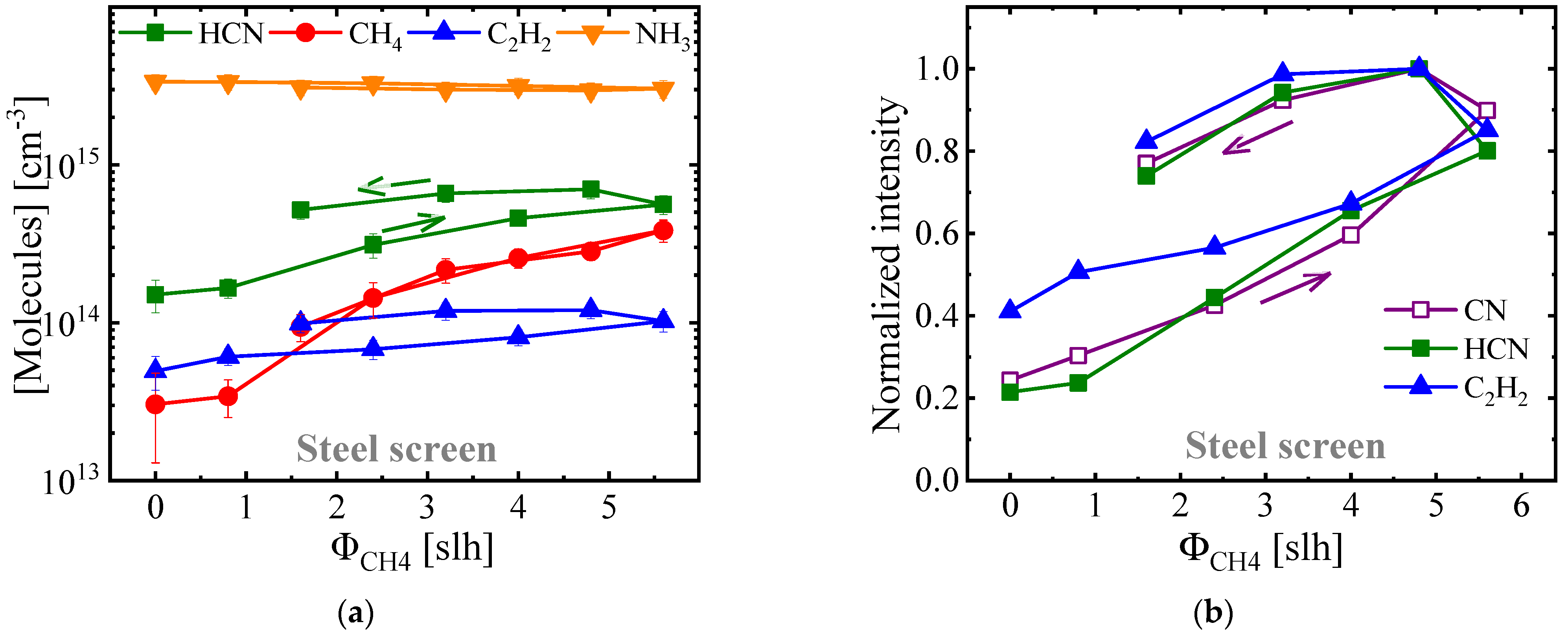
3.3. Comparison of Gaseous and Solid-State Carbon Precursors in ASPNC

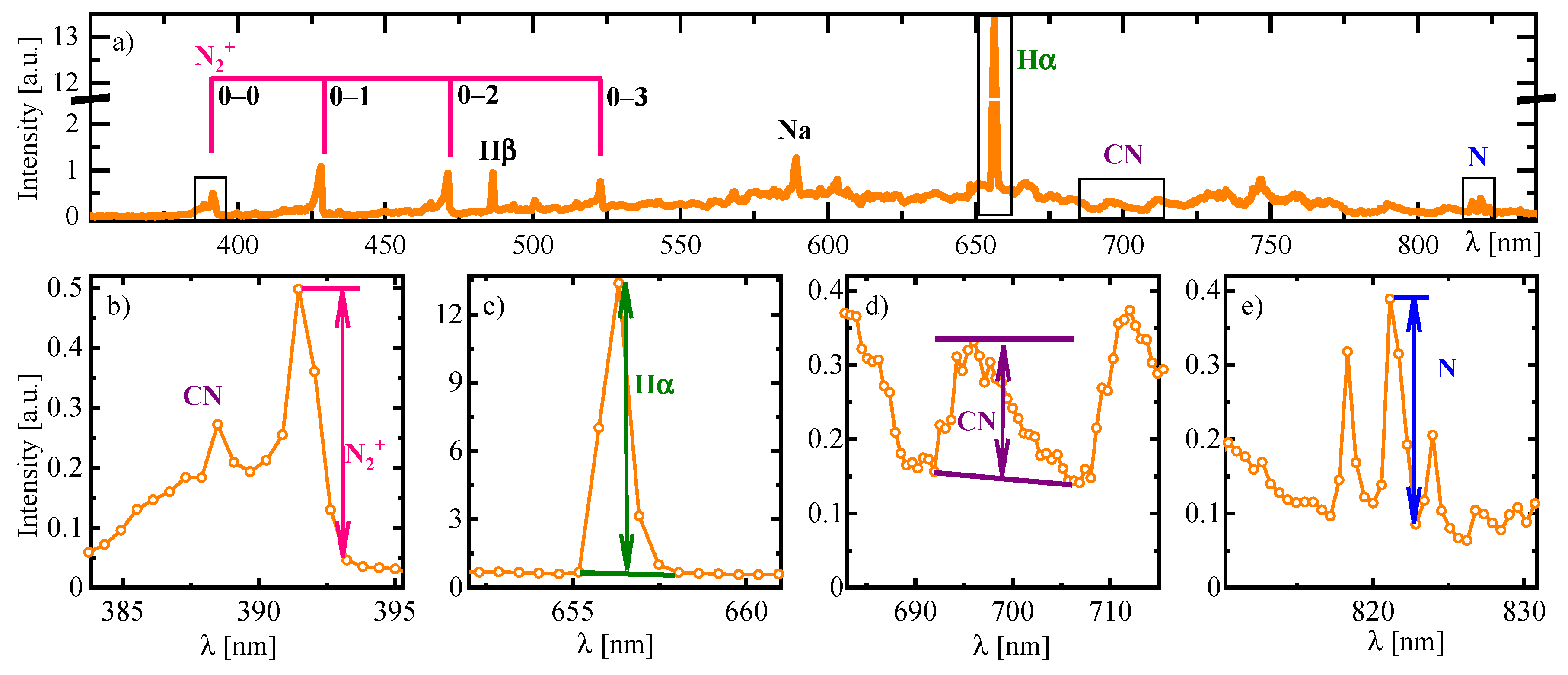
3.3.1. Plasma Diagnostics Using OES and LAS Techniques

Utilizing LAS and OES plasma diagnostic techniques, the changes of the plasma-chemical composition resulting from the application of different bias conditions was monitored both for a steel AS and a CFC-AS. For the OES, examples of the band of the CN violet system and the N2+ first positive system recorded at high resolution are shown in Figure 6 for different bias conditions using both AS materials. For the non-biased condition, the detectable emission originated only from the AS discharge. In addition, the N2+ head intensity increased with increasing bias power, indicating that the bias discharge efficiently ionized the molecular nitrogen in the vicinity of the applied bias discharge for both AS materials (Figure 6). As shown before (Figure 4), the intensity of CN was unstable and strongly dependent on the level of carbon-containing precursor gas, as well as the condition of the reactor in case of steel AS. Figure 6 shows that the CN emission remained nearly constant both for the non-biased and for the biased conditions using both AS materials. Thus, the CN emission could be considered to be independent from the bias condition for both AS materials. The intensity peaks measured at low resolution (see Figure 7) confirmed this observation and additionally showed an increase of the emissions from atomic nitrogen and hydrogen with increasing bias power using both AS materials. It is surprising that the CN emission was independent of the bias discharge power, unlike the emissions of other species, such as N2+, Hα, and N (Figure 7). For the use of a CFC-AS, it is possible to assume that CN was mainly formed near the AS discharge due to the chemical sputtering of the carbon surface by active nitrogen species. The amount of active species should be proportional to the total discharge power, i.e., the sum of the bias and AS discharge power, which did not change significantly. For the steel AS, the CN emission detected for the bias discharge condition probably compensated the reduction of the emission at the AS.
For both AS materials, HCN and NH3 were the two molecular species with the highest concentrations (Figure 8) according to the LAS measurements. Therefore, the concentration of NH3 was comparably high using both AS materials, and it slightly increased by a factor of approximately 1.3 with increasing bias power. However, for the CFC-AS, the concentration of HCN was higher by about a factor of three than that for the steel AS using a fixed CH4 admixture of ΦCH4 = 4 slh. Slight decreases by a factor of approximately 1.5 in the concentrations of HCN and C2H2 were observed when the bias power increased from 0 to 1.25 kW in the case of the CFC-AS (blue and green lines in Figure 8b). This can be explained based on the previously mentioned fact that, due to the application of a high bias discharge to the treated samples, an additional heat influx was introduced into the process, which in turn reduced the plasma power at the AS [47]. Consequently, as also shown by Puth et al. [39], a lower concentration of HCN was detected from the reduction of the AS plasma power in the case of the CFC-AS when a relatively high bias power was applied at the samples. However, for the steel AS, the concentrations of HCN and C2H2 remained largely unaffected by the bias power.

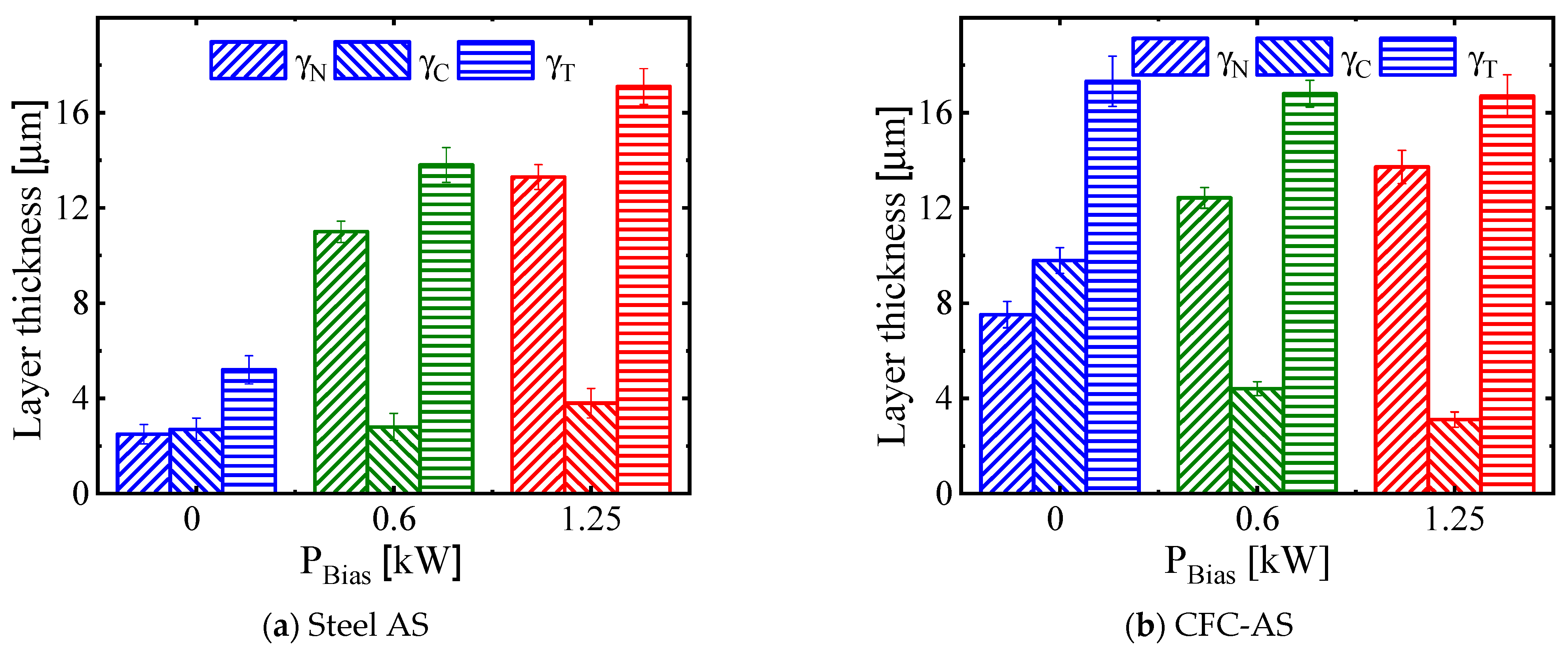
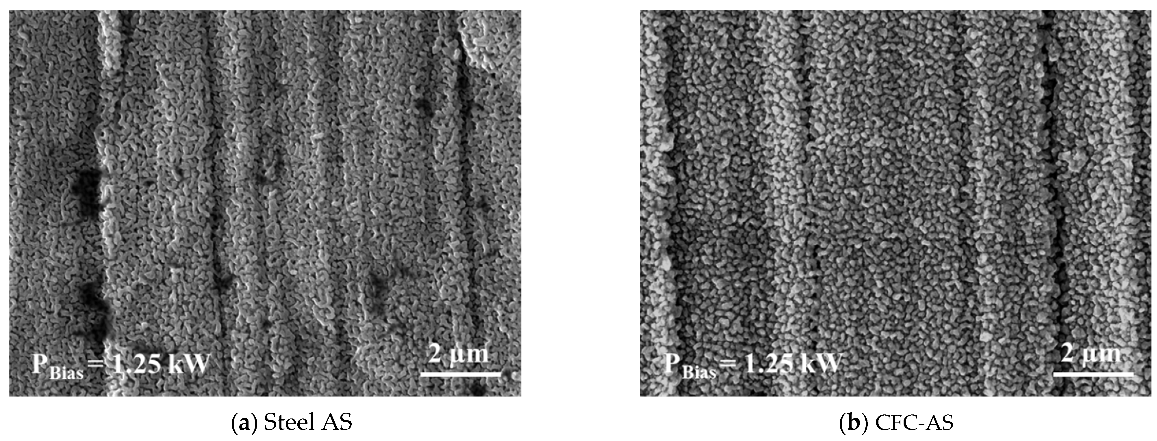
3.3.2. Characteristics of Expanded Austenite Layer

Cross-sectional optical micrographs of AISI 316L samples treated at different bias conditions using a steel AS and CH4 as a gaseous carbon-containing precursor (ΦCH4 = 4 slh) and a CFC-AS as a solid-state carbon precursor are shown in Figure 9. For all samples, the formation of a duplex layer composed of a nitrogen-expanded austenite layer γN on top and a subsurface carbon-expanded austenite layer γC was observed. In addition, Figure 10 shows the thicknesses of the γN and γC layers, as well as the total layer thickness γT, measured as a function of the bias power applied. For the non-biased condition (PBias = 0 kW, Figure 9a,d), i.e., without a bias discharge at the samples to be treated, for both the steel AS and the CFC-AS, the thicknesses of the γN and γC layers were nearly identical (γN ≅ γC, Figure 10). However, for the non-biased condition using the steel AS with addition of CH4 in the feed gas, the γN and γC layers were non-uniform in their thicknesses and a total layer thickness of γT = 5 µm (γN ≅ γC ≅ 2.5 µm) was observed (Figure 10a, blue columns). In contrast, for the CFC-AS with a non-biased condition, a total layer thickness of γT = 16 µm (γN ≅ γC ≅ 8 µm; Figure 10b, blue columns) was produced, which was an increase by a factor of three compared to the layer thickness obtained when using the steel AS. In addition, using the CFC-AS, the interface between the layer and the substrate was formed more uniformly (Figure 9d). Since the overall process parameters, such as temperature, pressure, time, and total gas flow rate, as well as the general plasma conditions were kept constant for the treatments using both AS materials, the differences in the resulting layer thickness can only be attributed to the reactive gas species generated by the respective states of the carbon precursors (Figure 8).
In the case of biased conditions (PBias = 0.6 and 1.25 kW, Figure 9b,c,e,f), for both AS materials, the thickness of the γN layer was increased while the thickness of the γC layer was reduced. Furthermore, it was found that, in the case of the CFC-AS, when increasing the bias plasma power from 0.6 kW to 1.25 kW, the total thickness of the expanded austenite layer γT did not change (Figure 10b). However, by using a steel AS, the total thickness of the expanded austenite layer γT was increased when the bias power was increased from 0.6 kW to 1.25 kW (Figure 10a).
Figure 11 shows the concentration depth profiles from GDOES analysis after ASPNC treatment with biased and non-biased conditions using a steel AS and a CFC-AS. In all treatment conditions, nitrogen displaced carbon and pushed the carbon atoms into deeper regions of the surface area. In the case of the non-biased condition, the diffusion depths of nitrogen and carbon, as well as their maximum contents, were higher for treatments using a CFC-AS compared to the treatments using a steel AS with CH4 admixture. For the biased conditions using both AS materials, the diffusion depth of nitrogen increased when the bias power was increased. The nitrogen diffusion depth exhibited maximum values of 15 µm for the steel AS (Figure 11a) and 20 µm for the CFC-AS (Figure 11b) in the case of 1.25 kW bias plasma power, which correlated with the estimated layer thickness of the expanded austenite from cross-sectional optical micrographs (Figure 10). Moreover, the high nitrogen and carbon contents near the surface can be explained in relation to the formation of nano-sized particles with high density on the surfaces of the ASPNC samples treated with biased conditions using both AS materials (Figure 12). It can be proposed that the nanoparticles formed at the surface were iron nitride, carbide, and carbonitride, as suggested by other researchers [50,51]. The formation of these nanoparticles could be attributed to sputtering of iron from the initial steel surface, which reacts with carbon and nitrogen active species and is re-deposited on the sample surface with a biased condition [51]. It is also worth mentioning that, in case of the 1.25 kW biased condition, the overall content of carbon (integrated area under the curve) using a steel AS was much higher than for the CFC-AS, whereas for the non-biased condition, it was vice versa. Moreover, for all investigated samples, the total contents of carbon and nitrogen were much higher for the CFC-AS than for the steel AS.
Figure 13 shows the X-ray diffraction patterns of AISI 316L treated using a steel AS and a CFC-AS with different biased conditions, as well as the untreated reference sample. For the untreated AISI 316L, two characteristic peaks were observed at angles of 51.1° and 59.7°, corresponding to the fcc γ(111) and γ(200) peaks of AISI 316L austenitic stainless steel, respectively. In the case of the ASPNC samples treated with biased conditions using both steel AS and CFC-AS, two defined peaks of the metastable nitrogen-expanded austenite appeared, indicated as γN(111) and γN(200), which were shifted to the lower angels and broader compared to the peaks of the untreated sample, respectively. In addition, it was revealed for both AS materials that the peak positions of γN(111) and γN(200) changed for the treatment with different bias conditions. For the sample treated with a non-biased condition using the CFC-AS, two defined peaks of the metastable nitrogen-expanded austenite, indicated as γN(111) and γN(200), appeared at angles shifted to lower values of around 48.2° and 54°, respectively. It was found that for a non-biased condition using both AS materials, the peaks of γC were visible due to the lower thickness of γN compared to the biased condition. In addition, it was observed that, for the non-biased condition, the diffraction peaks attributed to the γC phase were closer to the lines related to the untreated γ phase than those from the γN phase. This can be explained by the lower carbon content in the expanded austenite compared to the nitrogen content. The shift to lower angles and the anisotropic broadening of the diffraction peaks in the expanded austenite can be explained by the expansion of the fcc lattice due to the high nitrogen incorporation during ASPNC treatment and the associated formation of compressive stress, as well as concentration gradients. During ASPNC processes, the distortion of the lattice causes the formation of compressive residual stress, with the consequence that defects develop inside the grains, such as stacking faults, glide bands, and twins [52]. To avoid these undesired effects, it is necessary to reduce the nitrogen content in the γN layer, such as with the non-biased condition for the CFC-AS, and thus to preserve the surface state of the treated samples, as observed for the case without bias plasma power.
Figure 14 shows microhardness depth profiles according to the Knoop hardness measurement illustrating the increased surface hardness due to the formation of the expanded austenite after the ASPNC treatment at biased and non-biased conditions using a steel AS and a CFC-AS. For the non-biased condition using a steel AS, a low value for the maximum hardness of around 600 HK0.01 was achieved due to the formation of a thin γN layer and a decreased nitrogen concentration, while for the different biased conditions the maximum hardness increased to values of around 1200 HK0.01. In contrast, for the CFC-AS, a maximum hardness value of around 1400 HK0.01 for the non-biased condition was achieved, while for the biased-condition the maximum hardness value increased to up to about 1700 HK0.01 due to the formation of a thicker γN layer and a higher nitrogen concentration. Therefore, the hardness depth profiles were in reasonably good agreement with the GDOES profiles (Figure 11), as well as the measured layer thicknesses (Figure 10), for the treatments using both AS materials. In the case of the non-biased condition. for both AS materials, the low content of N measured by the GDOES led to lower hardness at the surface compared to the biased condition using the same AS material.

4. Discussion

The concentration of HCN was proposed as a reliable monitoring parameter for the carburizing effect during nitrocarburizing treatments by Burlacov et al. [31,32]. In the case of ASPNC with a steel AS, the CH4 flow rate can be adjusted in accordance with the measured HCN concentration. However, the control of the carburizing effect by the CH4 admixture level with the steel AS was challenging in terms of plasma-chemical composition aspects, as can be seen from the hysteresis of the CN emission and the HCN absorption signals (Figure 5b), whereas the concentration of CH4 coincided for forward and back measurements (Figure 5a). Within the industrial-scale ASPNC reactor used for the investigation, the residence time of each molecule inside the reactor was estimated to be about 1 min due to the gas flow. A waiting time of approximately 20 min was maintained before the LAS and OES measurements in order to stabilize the discharge condition. This time was sufficient to reach an equilibrium in the CH4 concentration, supplied by the input gas flow. However, the concentrations of generated HCN and C2H2 molecules inside the process atmosphere were influenced not only by the CH4 admixture level in the H2-N2 feed gas, but also by the carbon contamination of the reactor walls and/or the steel AS. The time required to reach an equilibrium concentration in the HCN and the C2H2 molecules, contributing to the carburising effect, depends on the history of the reactor as well as the ASPNC treatment duration. In addition, an uncontrolled temperature of the reactor wall can change the balance between the deposition and the release of carbon from such decontamination sites. Therefore, it can be proposed that the concentrations of HCN and/or C2H2 can be considered as reliable monitoring parameters for the carburizing effect during nitrocarburizing treatments. Thus, the real-time monitoring of carbon-containing species, such as HCN and C2H2, during the ASPNC treatment could provide further insights into the plasma-chemical composition of the process gas using a steel AS and gaseous carbon-containing precursor.
The potential and limitations of ASPNC treatments using a CH4 gaseous carbon-containing precursor with a steel AS and a solid-state carbon precursor in a CFC-AS can be discussed based on the concentrations of HCN and/or C2H2, as well as the bias conditions. As mentioned previously, there are two main mechanisms for the removal of the chromium oxide passive layer at the stainless steel surface: (i) surface sputtering for the biased condition [15] and (ii) interaction of HCN and/or C2H2 with the steel surface for both the non-biased and biased conditions [16,18,20]. For the treatments with non-biased or ”afterglow” conditions investigated in this study, the concentrations of HCN and C2H2 increased by about a factor of approximately 2.7 for the CFC-AS compared to the steel AS with 5% CH4 admixture (Figure 8). Therefore, during the afterglow treatment using a steel AS, due to the relatively low concentrations of HCN and C2H2 (Figure 8a), as well as the absence of the active discharge bias at the sample surface, the removal of the passive oxide layer was not efficient and was relatively slow. As a result, only a thin and non-uniform expanded austenite layer formed during the 5 h of ASPNC treatment (Figure 9a). In contrast, for the treatment using the CFC-AS in an afterglow condition, the generation of HCN and C2H2 in high concentrations (Figure 8b) effectively de-passivated the stainless steel surface. Consequently, a thicker and more uniform expanded austenite layer was formed (Figure 9d).
Assuming the simplest case of a diffusion-controlled reaction, the formation and the thickness of the total expanded austenite layer is proportional to the square root of the treatment time according to Fick’s first law. Therefore, in the case of a steel AS, the total layer thickness of expanded austenite increases when the bias power is increased, as it accelerates the surface activation and consequently increases the time available for the diffusion process compared to non-biased and low-biased conditions (Figure 9b,c). In contrast, for a CFC-AS, the removal of the passive oxide layer is mainly governed by chemically active HCN and C2H2 molecules, as they were detected in high concentrations within the resulting process gas. Thus, when utilizing a CFC-AS, the total layer thickness of expanded austenite is independent of the bias condition applied (Figure 9d–f).
Using both AS materials and applying a biased condition, the thickness of the nitrogen-expanded austenite γN layer was noticeably increased compared to the non-biased condition (Figure 10), and it was accompanied by a rise in the NH3 concentration within the process gas atmosphere (Figure 8). In addition, by applying higher bias power at the samples, these effects became more pronounced. In analogy to gas nitriding processes, NH3 could have been responsible for the nitriding effect, but its concentration variation from changing the bias power seems to be too small for it to be a possible explanation of the detected γN layer variation (Figure 10). Besides, considering the OES measurements, the intensity of the N2+ ion emission increased with increasing bias power (Figure 6 and Figure 7), indicating that the active discharge efficiently ionized the molecular nitrogen in the vicinity of the sample surface. Since positive ions are attracted by negatively charged surfaces, they were most probably responsible for the increase of the γN layer thickness. Moreover, it can be proposed that the surface under bias voltage efficiently attracted N2+ and N+ ions, which in turn enhanced the production of NH3.
Additionally, it can be assumed that, in the case of the non-biased condition, the main species for both nitriding and carburizing was HCN. Indeed, for both AS materials in the non-biased condition, the thicknesses of the γN and γC layers increased proportionally, leading to γN ≈ γC (Figure 9a,d). This means that the ratio between nitriding and carburizing effects remained constant. Taking into account that the HCN concentration is a reliable parameter for the carburizing effect [31] and that the ratio of HCN and NH3 concentrations significantly varies with the AS material, it can be concluded that NH3 should not have influenced the nitriding effect significantly. In contrast, HCN brings the same amounts of C and N atoms to the surface, the diffusion rates of which are proportional to their activity coefficients in the metal [53], and this would keep the ratio of C and N atom concentrations in the metal constant. However, further investigations are required to clarify whether the NH3 concentration could reflect the nitriding effect within plasma-assisted thermochemical treatments.
The special role of HCN molecules in carburizing and nitriding, as well as in activation of the oxide layer, during ASPNC of austenitic stainless steel was discussed in our previous work [47]. There, a cylindrical substrate holder with side slits was applied, which prohibited the access of charged particles to the back side of the sample. An expanded austenite layer with equal thickness of γN and γC was formed at the sample back side during the treatment with CFC-AS. It was shown that the total layer thickness was reduced even with the applied bias voltage. The current work provides support for this assumption regarding the dual function of HCN molecules in the comparable ASPNC treatments using a steel AS and a CFC-AS under different bias conditions, as well as in the spectroscopic measurements of the treatment atmospheres. Additionally, it can be noted that the slight increase of the NH3 concentration with increasing bias (Figure 10) had no significant influence on the thickness ratio of γNC on the sample back side [47], which supports the assumption about the minor contribution of NH3 in nitriding in the current investigations.
The reduction of the carbon content as well as the thickness of the carbon-expanded austenite γC layer within the generated total expanded austenite layer after ASPNC treatment with the CFC-AS (Figure 10b and Figure 11b) can be correlated with the reduction of the concentrations of HCN and C2H2 measured by LAS (Figure 8b). In addition, because the reduction of the γC layer thickness was compensated by the increase of the γN layer thickness, it is possible to assume that the number of atoms diffusing into the steel surface per unit of time was restricted by the surface area. Thus, both the nitrogen and the carbon atoms would have had to compete to diffuse into the steel surface. Taking the abovementioned points into account, the enhancement of the nitrogen diffusion inside the steel surface could be an alternative explanation for the reduction of the γC layer thickness using CFC-AS. It is worth mentioning here that, although the contamination of the reactor wall by carbon or carbon-containing species occurred during the treatments using both AS materials, in treatments with long durations, uncontrollable contamination even up to full saturation of the steel AS is still a factor of uncertainty for the carburizing effect. However, a reliable conclusion about the correlation of the detectable reactive species and the carburizing effect, as well as a direct comparison of the plasma-chemical compositions within processes using a gaseous carbon-containing precursor in the case of a steel AS and a solid-state carbon precursor in the case of a CFC-AS, requires (i) monitoring of the concentration during the real-time ASPNC treatment and (ii) the opportunity for the gradual variation of the HCN concentration between conditions with CFC and steel AS.

5. Conclusions

ASPNC treatments in an industrial-scale cold-wall reactor using ASs made of two different materials, i.e., steel and CFC, were investigated with the example of AISI 316L austenitic stainless steel. Plasma diagnostic techniques including LAS and OES were complementarily utilized to analyse the influence of the CH4 admixture level on the steel AS, as well as the applied biased discharge power on the resulting process gas atmosphere for both AS materials. In addition, the changes of the structural properties and the hardness gradients within the generated expanded austenite layers were validated using characterization methods. It was revealed from LAS and OES plasma diagnostics that for long treatment times with the steel AS and CH4 as a gaseous carbon-containing precursor, the AS and/or reactor walls became contaminated and thus represented an additional source of carbon or HCN/C2H2, which were partly released again into the process gas atmosphere taking part in plasma-chemical reactions. Therefore, rising contributions from the steel AS and/or reactor walls as undesired sources for carbon or HCN/C2H2 should be taken into consideration to enable reliable process control of the nitriding and carburizing effects in the treatment atmosphere. This can be achieved through the application of real-time non-intrusive in situ plasma diagnostic methods during the treatment.
The results of the LAS plasma diagnostics indicated that the bias power only had a minor influence on the gas composition, whereas much higher concentrations of HCN and C2H2 molecules were generated in the case of the CFC-AS compared to the steel AS. It was concluded that these molecules could have been responsible for the effective removal of the passive layer of the stainless steel samples. In the case of the steel AS, their concentrations were insufficient, and thus the application of the bias power accelerated the removal of the passive layer via ion bombardment. In addition, applying a bias power increased the thickness of the γN layer for both AS materials. It was suggested that nitrogen ions generated in the vicinity of the sample were responsible for this effect.
It is important to note that, in the non-biased condition for both AS materials, the thicknesses of the γN and γC layers were comparable, but the total expanded austenite layer thicknesses of the samples treated by CFC-AS was about three times larger than with the steel AS. This observation can be interpreted on the basis of the dual capacity of HCN for (i) activation of the passivated surface and (ii) transportation of both nitrogen and carbon to the materials’ surfaces, providing diffusible nitrogen and carbon atoms and ensuring the diffusion during the thermochemical treatment of the stainless steels.
It was demonstrated that the choice of the AS material has an influence on the treatment results. For a steel AS, the thickness of the expanded austenite layer strongly depends on the bias power. Non-biased conditions result in a thin and inhomogeneous layer after 5 h of treatment. Therefore, the application of a cathodic bias discharge to the samples is essential to achieve an acceptable nitrocarburizing effect. This is in contrast to the AS made of CFC, for which the total layer thickness was independent on the bias conditions.
In summary, the CFC-AS provides new opportunities for bulk treatment of massive loads of austenitic stainless steel components with non-biased conditions compared to the steel AS. In addition, treatment with a CFC-AS is less influenced by contamination of the AS and consequently can provide better control of the treatment process. However, the main disadvantage of the CFC-AS is related to the high cost of the CFC material consumed during the treatment process, as well as the complexity in the manufacturing of the AS made of CFC.

Author Contributions

Conceptualization, S.M.J. and A.D.; Data curation, S.M.J., A.V.P. and A.P.; Funding acquisition, J.R. and H.B.; Investigation, S.M.J., A.V.P. and A.P.; Methodology, S.M.J. and A.D.; Supervision, J.R., J.-P.H.v.H. and H.B.; Writing—original draft, S.M.J.; Writing—review & editing, A.V.P., A.D., J.R., J.-P.H.v.H. and H.B. All authors have read and agreed to the published version of the manuscript.

Funding

This research was funded by the Federal Ministry of Education and Research (BMBF) with grant numbers 03VP05501 and 03VP05502. Open Access Funding by the Publication Fund of the TU Bergakademie Freiberg.

Institutional Review Board Statement

Not applicable.

Informed Consent Statement

Not applicable.

Data Availability Statement

Not applicable.

Acknowledgments

The authors appreciate the Federal Ministry of Education and Research (BMBF) for financial support in the framework of the validation funding VIP+ in the project PNC Control, project numbers 03VP05501 and 03VP05502. The authors thank Ch. Schimpf (TU Bergakademie Freiberg, Institute of Materials Science) for XRD analysis and I. Diegel (TU Bergakademie Freiberg, Institute of Materials Engineering) for metallographic preparation as well as hardness measurements.

Conflicts of Interest

The authors declare no conflict of interest.

References

  1. Bell, T. Surface engineering of austenitic stainless steel. Surf. Eng. 2002, 18, 415–422. [Google Scholar] [CrossRef]
  2. Lo, K.H.; Shek, C.H.; Lai, J.K.L. Recent developments in stainless steels. Mater. Sci. Eng. R Rep. 2009, 65, 39–104. [Google Scholar] [CrossRef]
  3. Dong, F.Y.; Zhang, P.; Pang, J.C.; Chen, D.M.; Yang, K.; Zhang, Z.F. Optimizing strength and ductility of austenitic stainless steels through equal-channel angular pressing and adding nitrogen element. Mater. Sci. Eng. A 2013, 587, 185–191. [Google Scholar] [CrossRef]
  4. Mendes, A.F.; Scheuer, C.J.; Joanidis, I.L.; Cardoso, R.P.; Mafra, M.; Klein, A.N.; Brunatto, S.F. Low-temperature plasma nitriding of sintered PIM 316L austenitic stainless steel. Mater. Res. 2014, 17, 100–109. [Google Scholar] [CrossRef] [Green Version]
  5. De Las Heras, E.; Ybarra, G.; Lamas, D.; Cabo, A.; Dalibon, E.L.; Brühl, S.P. Plasma nitriding of 316L stainless steel in two different N2-H2 atmospheres—Influence on microstructure and corrosion resistance. Surf. Coat. Technol. 2017, 313, 47–54. [Google Scholar] [CrossRef]
  6. Sun, Y.; Li, X.; Bell, T. Low temperature plasma carburising of austenitic stainless steels for improved wear and corrosion resistance. Surf. Eng. 1999, 15, 49–54. [Google Scholar] [CrossRef]
  7. García Molleja, J.; Nosei, L.; Ferrón, J.; Bemporad, E.; Lesage, J.; Chicot, D.; Feugeas, J. Characterization of expanded austenite developed on AISI 316L stainless steel by plasma carburization. Surf. Coat. Technol. 2010, 204, 3750–3759. [Google Scholar] [CrossRef]
  8. Chen, F.-S.; Chang, C.-N. Effect of CH4 addition on plasma nitrocarburizing of austenitic stainless steel. Surf. Coat. Technol. 2003, 173, 9–18. [Google Scholar] [CrossRef]
  9. Cheng, Z.; Li, C.X.; Dong, H.; Bell, T. Low temperature plasma nitrocarburising of AISI 316 austenitic stainless steel. Surf. Coat. Technol. 2005, 191, 195–200. [Google Scholar] [CrossRef]
  10. Czerwiec, T.; He, H.; Marcos, G.; Thiriet, T.; Weber, S.; Michel, H. Fundamental and Innovations in Plasma Assisted Diffusion of Nitrogen and Carbon in Austenitic Stainless Steels and Related Alloys. Plasma Process. Polym. 2009, 6, 401–409. [Google Scholar] [CrossRef]
  11. Sun, Y.; Haruman, E. Low Temperature Plasma Surface Alloying of Austenitic Stainless Steels. Solid State Phenom. 2006, 118, 85–90. [Google Scholar] [CrossRef]
  12. Manova, D.; Lotnyk, A.; Mändl, S.; Neumann, H.; Rauschenbach, B. CrN precipitation and elemental segregation during the decay of expanded austenite. Mater. Res. Express 2016, 3, 66502. [Google Scholar] [CrossRef]
  13. Dimitrov, V.I.; D’Haen, J.; Knuyt, G.; Quaeyhaegens, C.; Stals, L.M. A method for determination of the effective diffusion coefficient and sputtering rate during plasma diffusion treatment. Surf. Coat. Technol. 1998, 99, 234–241. [Google Scholar] [CrossRef]
  14. Baranowska, J. Characteristic of the nitride layers on the stainless steel at low temperature. Surf. Coat. Technol. 2004, 180–181, 145–149. [Google Scholar] [CrossRef]
  15. Saker, A.; Leroy, C.; Michel, H.; Frantz, C. Properties of sputtered stainless steel-nitrogen coatings and structural analogy with low temperature plasma nitrided layers of austenitic steels. Mater. Sci. Eng. A 1991, 140, 702–708. [Google Scholar] [CrossRef]
  16. Christiansen, T.L.; Hummelshøj, T.S.; Somers, M.A.J. Gaseous carburising of self-passivating Fe–Cr–Ni alloys in acetylene–hydrogen mixtures. Surf. Eng. 2011, 27, 602–608. [Google Scholar] [CrossRef]
  17. Song, Y.; Kim, J.-H.; Kim, K.-S.; Kim, S.; Song, P. Effect of C2H2/H2 Gas Mixture Ratio in Direct Low-Temperature Vacuum Carburization. Metals 2018, 8, 493. [Google Scholar] [CrossRef] [Green Version]
  18. Christiansen, T.L.; Hummelshøj, T.S.; Somers, M.A.J. A Method of Activating an Article of Passive Ferrous or Non-Ferrous metal Prior to Carburizing, Nitriding and/or Nitrocarburizing. EP Patent 2278038 A1, 26 January 2011. [Google Scholar]
  19. Somers, M.A.J.; Christiansen, T.L. Carburizing in Hydrocarbon Gas. WO Patent 2006/136166 A1, 28 December 2006. [Google Scholar]
  20. Hoshino, K.; Miyashita, M.; Kawamura, T.; Totsuka, T.; Eiraku, H.; Yashiro, K.; Kurosawa, T. Method for Activating Surface of Metal Member. EP Patent 1707646 A1, 4 October 2006. [Google Scholar]
  21. Baranowska, J. Importance of surface activation for nitrided layer formation on austenitic stainless steel. Surf. Eng. 2010, 26, 293–298. [Google Scholar] [CrossRef]
  22. Spies, H.-J.; Eckstein, C.; Biermann, H.; Franke, A. Corrosion behaviour of stainless steels after low temperature thermochemical treatment. Mater. Werkst. 2010, 41, 133–141. [Google Scholar] [CrossRef]
  23. Sun, Y. Production of nitrogen and carbon S phases in austenitic stainless steels by hybrid plasma surface alloying. Surf. Eng. 2010, 26, 114–122. [Google Scholar] [CrossRef]
  24. Lin, K.; Li, X.; Sun, Y.; Luo, X.; Dong, H. Active screen plasma nitriding of 316 stainless steel for the application of bipolar plates in proton exchange membrane fuel cells. Int. J. Hydrogen Energy 2014, 39, 21470–21479. [Google Scholar] [CrossRef]
  25. Georges, J. Nitriding Process and Nitriding Furnace Therefor. U.S. Patent 5,989,363, 23 November 1999. [Google Scholar]
  26. Li, C.X.; Georges, J.; Li, X.Y. Active screen plasma nitriding of austenitic stainless steel. Surf. Eng. 2002, 18, 453–457. [Google Scholar] [CrossRef]
  27. Hubbard, P.; Dowey, S.J.; Doyle, E.D.; McCulloch, D.G. Influence of bias and in situ cleaning on through cage (TC) or active screen plasma nitrided (ASPN) steels. Surf. Eng. 2006, 22, 243–247. [Google Scholar] [CrossRef]
  28. Hubbard, P.; Dowey, S.J.; Partridge, J.G.; Doyle, E.D.; McCulloch, D.G. Investigation of nitrogen mass transfer within an industrial plasma nitriding system II: Application of a biased screen. Surf. Coat. Technol. 2010, 204, 1151–1157. [Google Scholar] [CrossRef]
  29. Olzon-Dionysio, M.; Campos, M.; Kapp, M.; de Souza, S.; de Souza, S.D. Influences of plasma nitriding edge effect on properties of 316L stainless steel. Surf. Coat. Technol. 2010, 204, 3623–3628. [Google Scholar] [CrossRef]
  30. Ahangarani, S.; Sabour, A.R.; Mahboubi, F. Surface modification of 30CrNiMo8 low-alloy steel by active screen setup and conventional plasma nitriding methods. Appl. Surf. Sci. 2007, 254, 1427–1435. [Google Scholar] [CrossRef]
  31. Burlacov, I.; Hamann, S.; Spies, H.-J.; Röpcke, J.; Biermann, H. In-line Process Control in the Active Screen Plasma Nitrocarburizing Using a Combined Approach Based on Infrared Laser Absorption Spectroscopy and Bias Power Management. HTM J. Heat Treat. Mater. 2016, 71, 141–147. [Google Scholar] [CrossRef]
  32. Burlacov, I.; Hamann, S.; Spies, H.-J.; Röpcke, J.; Biermann, H. On the influence of carbon contamination of reactor parts in active screen plasma nitrocarburizing processes. J. Appl. Phys. 2018, 123, 233302. [Google Scholar] [CrossRef]
  33. Haruman, E.; Bell, T.; Sun, Y. Compound Layer Characteristics Resulting from Plasma Nitrocarburising in Atmospheres Containing Carbon Dioxide Gas Additions. Surf. Eng. 1992, 8, 275–282. [Google Scholar] [CrossRef]
  34. Burlacov, I.; Hamann, S.; Spies, H.-J.; Dalke, A.; Röpcke, J.; Biermann, H. A Novel Approach of Plasma Nitrocarburizing Using a Solid Carbon Active Screen—a Proof of Concept. HTM J. Heat Treat. Mater. 2017, 72, 254–259. [Google Scholar] [CrossRef]
  35. Dalke, A.; Burlacov, I.; Spies, H.-J.; Biermann, H. Use of a solid carbon precursor for DC plasma nitrocarburizing of AISI 4140 steel. Vacuum 2018, 149, 146–149. [Google Scholar] [CrossRef]
  36. Burlacov, I.; Spies, H.-J.; Biermann, H. Vorrichtung zur Vorrichtung zur Plasmagestützten Erzeugung von Hochreaktiven Prozessgasen auf Basis ungesättigter H-C-N-Verbindungen, die zur Anreicherung der Randschicht von metallischen Bauteilen mit erhöhtem Stickstoff- und/oder Kohlenstoffanteil beitragen. DE Patent 10 2013 006 589 A1, 19 April 2018. [Google Scholar]
  37. Schlüter, M.; Hopf, C.; Jacob, W. Chemical sputtering of carbon by combined exposure to nitrogen ions and atomic hydrogen. New J. Phys. 2008, 10, 53037. [Google Scholar] [CrossRef] [Green Version]
  38. Jacob, W.; Hopf, C.; Schlüter, M. Chemical sputtering of carbon by nitrogen ions. Appl. Phys. Lett. 2005, 86, 204103. [Google Scholar] [CrossRef]
  39. Puth, A.; Hamann, S.; Kusýn, L.; Burlacov, I.; Dalke, A.; Spies, H.-J.; Biermann, H.; Röpcke, J. Spectroscopic investigations of plasma nitrocarburizing processes using an active screen made of carbon in a model reactor. Plasma Sources Sci. Technol. 2018, 27, 75017. [Google Scholar] [CrossRef]
  40. Hamann, S.; Burlacov, I.; Spies, H.-J.; Biermann, H.; Röpcke, J. Spectroscopic investigations of plasma nitriding processes: A comparative study using steel and carbon as active screen materials. J. Appl. Phys. 2017, 121, 153301. [Google Scholar] [CrossRef]
  41. Hamann, S.; Börner, K.; Burlacov, I.; Spies, H.-J.; Röpcke, J. Spectroscopic diagnostics of active screen plasma nitriding processes: On the interplay of active screen and model probe plasmas. J. Phys. D Appl. Phys. 2015, 48, 345204. [Google Scholar] [CrossRef]
  42. Cleugh, D. Plasma species analysis for insitu assessment of surface treatments. Surf. Eng. 2002, 18, 133–139. [Google Scholar] [CrossRef]
  43. Dalke, A.; Burlacov, I.; Hamann, S.; Puth, A.; Spies, H.-J.; Röpcke, J.; Biermann, H. Plasma Nitrocarburizing of AISI 316L Austenitic Stainless Steel Applying a Carbon Active Screen: Status and Perspectives. HTM J. Heat Treat. Mater. 2018, 73, 246–257. [Google Scholar] [CrossRef]
  44. Dalke, A.; Burlacov, I.; Hamann, S.; Puth, A.; Böcker, J.; Spies, H.-J.; Röpcke, J.; Biermann, H. Solid carbon active screen plasma nitrocarburizing of AISI 316L stainless steel: Influence of N2-H2 gas composition on structure and properties of expanded austenite. Surf. Coat. Technol. 2019, 357, 1060–1068. [Google Scholar] [CrossRef]
  45. Maniee, A.; Mahboubi, F.; Soleimani, R. The study of tribological and corrosion behavior of plasma nitrided 34CrNiMo6 steel under hot and cold wall conditions. Mater. Des. 2014, 60, 599–604. [Google Scholar] [CrossRef]
  46. Pye, D. Practical Nitriding and Ferritic Nitrocarburizing; ASM International: Materials Park, OH, USA, 2003. [Google Scholar]
  47. Jafarpour, S.M.; Puth, A.; Dalke, A.; Böcker, J.; Pipa, A.V.; Röpcke, J.; van Helden, J.H.; Biermann, H. Solid carbon active screen plasma nitrocarburizing of AISI 316L stainless steel in cold wall reactor: Influence of plasma conditions. J. Mater. Res. Technol. 2020, 9, 9195–9205. [Google Scholar] [CrossRef]
  48. Pintassilgo, C.D.; Jaoul, C.; Loureiro, J.; Belmonte, T.; Czerwiec, T. Kinetic modelling of a N2 flowing microwave discharge with CH 4 addition in the post-discharge for nitrocarburizing treatments. J. Phys. D Appl. Phys. 2007, 40, 3620–3632. [Google Scholar] [CrossRef]
  49. Pintassilgo, C.D.; Loureiro, J.; Cernogora, G.; Touzeau, M. Methane decomposition and active nitrogen in a N2-CH4glow discharge at low pressures. J. Phys. D Appl. Phys. 1999, 8, 463–478. [Google Scholar] [CrossRef]
  50. Heydarzadeh Sohi, M.; Ebrahimi, M.; Honarbakhsh Raouf, A.; Mahboubi, F. Effect of plasma nitrocarburizing temperature on the wear behavior of AISI 4140 steel. Surf. Coat. Technol. 2010, 205, S84–S89. [Google Scholar] [CrossRef]
  51. Naeem, M.; Iqbal, J.; Zakaullah, M.; Shafiq, M.; Mujahid, Z.I.; Díaz-Guillén, J.C.; Lopez-Badillo, C.M.; Sousa, R.R.M.; Khan, M.A. Enhanced wear and corrosion resistance of AISI-304 steel by duplex cathodic cage plasma treatment. Surf. Coat. Technol. 2019, 375, 34–45. [Google Scholar] [CrossRef]
  52. Sun, Y.; Li, X.Y.; Bell, T. X-ray diffraction characterisation of low temperature plasma nitrided austenitic stainless steels. J. Mater. Sci. 1999, 34, 4793–4802. [Google Scholar] [CrossRef]
  53. Slycke, J.; Ericsson, T. A study of reactions occurring during the carbonitriding process part II. J. Heat Treat. 1981, 2, 97–112. [Google Scholar] [CrossRef]
Figure 1. Schematic diagrams of the industrial-scale cold-wall ASPNC reactor (a), the plasma diagnostics setup (b), a loaded sample platform for material treatments (c), and a model probe for plasma diagnostics (d) placed at the treatment area (indicated by the dash line) in the centre of the reactor. TE indicates the positions of the thermocouples and A is the beam path.
Metals 11 01411 g001aMetals 11 01411 g001b
Figure 2. An example of the overview optical emission spectrum recorded by the low-resolution spectrometer with a steel AS at H2:N2 = 1:1, p = 3 mbar, T = 460 °C, ΦTotal = 80 slh, ΦCH4 = 4 slh, PAS = 5.8 kW, and PBias = 0.6 kW (a). Selected regions are zoomed in (be), with the arrows indicating the respective evaluations of peak intensities for N2+ (b), Hα (c), CN (d), and N (e).
Metals 11 01411 g002
Figure 3. AS plasma power as a function of bias plasma power for steel AS (ΦCH4 = 4 slh), indicated in blue, and CFC-AS, indicated in red, at H2:N2 = 1:1, p = 3 mbar, T = 460 °C, and ΦTotal = 80 slh (closed symbols: extracted during material treatments; open symbols: extracted during the spectroscopic investigations).
Metals 11 01411 g003
Figure 4. Development of peak intensities with variation of CH4 admixture level recorded with high- (a) and low- resolution (b) spectrometers during ASPNC treatment using a steel AS at H2:N2 = 1:1, p = 3 mbar, T = 460 °C, ΦTotal = 80 slh, and PBias = 1.25 kW. Lines are guides for the eye and arrows indicate the order of measurements.
Metals 11 01411 g004
Figure 5. Concentrations of HCN, C2H2, CH4, and NH3 measured as functions of the CH4 flow rate from LAS (a) and comparison of normalized signals of CN from high-resolution OES and HCN and C2H2 from LAS (b) during ASPNC treatment using a steel AS at H2:N2 = 1:1, p = 3 mbar, T = 460 °C, ΦTotal = 80 slh, and PBias = 1.25 kW. Lines are guides for the eye and arrows indicate the order of measurements.
Metals 11 01411 g005
Figure 6. CN and N2+ emission bands as functions of the bias power, measured with high-resolution OES during ASPNC treatment using a steel AS (ΦCH4 = 4 slh) (a) and a CFC-AS (b) at H2:N2 = 1:1, p = 3 mbar, T = 460 °C, and ΦTotal = 80 slh. The intensities are normalized to the N2+ peak intensity at PBias = 1.25 kW.
Metals 11 01411 g006
Figure 7. Peak intensities of CN, N2+, H, and N as functions of the bias power measured with low-resolution OES during ASPNC treatment using a steel AS (ΦCH4 = 4 slh) (a) and a CFC-AS (b) at H2:N2 = 1:1, p = 3 mbar, T = 460 °C, and ΦTotal = 80 slh. The intensities are normalized to their respective values at a maximum bias power of 1.25 kW.
Metals 11 01411 g007
Figure 8. Concentrations of CH4, NH3, HCN, and C2H2 measured as functions of the bias plasma power during ASPNC treatment using a steel AS (ΦCH4 = 4 slh) (a) and a CFC-AS (b) at H2:N2 = 1:1, T = 460 °C, ΦTotal = 80 slh, and p = 3 mbar.
Metals 11 01411 g008
Figure 9. Cross-sectional optical micrographs of 316L after ASPNC by applying different bias conditions using a steel AS (ΦCH4 = 4 slh) (ac) and a CFC-AS (df) (etchant: Beraha II) at H2:N2 = 1:1, p = 3 mbar, T = 460 °C, ΦTotal = 80 slh, and t = 5 h.
Metals 11 01411 g009aMetals 11 01411 g009b
Figure 10. Thicknesses of γN and γC layers, as well as the total layer thickness γT, as a function of bias power for an AS made of steel (ΦCH4 = 4 slh) (a) and of CFC (b) determined from cross-sectional optical micrographs of ASPNC-treated samples at H2:N2 = 1:1, p = 3 mbar, T = 460 °C, ΦTotal = 80 slh, and t = 5 h.
Metals 11 01411 g010
Figure 11. GDOES concentration depth profiles of nitrogen and carbon (in at.%) after ASPNC treatment at different bias conditions for a steel AS (ΦCH4 = 4 slh) (a) and a CFC-AS (b) at H2:N2 = 1:1, p = 3 mbar, T = 460 °C, ΦTotal = 80 slh, and t = 5 h.
Metals 11 01411 g011
Figure 12. Top-view SEM images of samples after ASPNC treatment for a steel AS (ΦCH4 = 4 slh) (a) and a CFC-AS (b) at H2:N2 = 1:1, p = 3 mbar, T = 460 °C, ΦTotal = 80 slh, PBias = 1.25 kW, and t = 5 h.
Metals 11 01411 g012
Figure 13. X-ray diffraction pattern measured at the surface of ASPNC samples treated at different bias conditions for a steel AS (ΦCH4 = 4 slh) (a) and a CFC-AS (b) at H2:N2 = 1:1, p = 3 mbar, T = 460 °C, ΦTotal = 80 slh, and t = 5 h.
Metals 11 01411 g013
Figure 14. Microhardness depth profiles measured in the cross-sections of samples treated with different bias conditions for a steel AS (ΦCH4 = 4 slh) (a) and a CFC-AS (b) at H2:N2 = 1:1, p = 3 mbar, T = 460 °C, ΦTotal = 80 slh, and t = 5 h.
Metals 11 01411 g014
Publisher’s Note: MDPI stays neutral with regard to jurisdictional claims in published maps and institutional affiliations.

