Abstract
Laser powder bed fusion (LPBF) technology is beneficial for the fabrication of thermal conductive materials, integrating with the predesigned structure, which shows a great potential for high heat dissipation applications. Here, a Cu–Cr–Zr alloy with relative density of 98.53% is successfully prepared by LPBF after process optimization. On this basis, microstructure, phase identification, precipitates, mechanical and thermal properties are investigated. The results demonstrate that the surface morphology of microstructure is affected by laser energy density, the α-Cu is the main phase of the LPBF sample and the virgin powder, the size of Cr spherical precipitates in some areas is about 1 μm, and the tensile fracture mode is a mixed ductile–brittle mode. Furthermore, the Vickers hardness of the LPBF Cu–Cr–Zr sample is 70.7 HV to 106.1 HV, which is higher than that of LPBF Cu and a wrought C11000 Cu, and the difference in Vickers hardness of different planes reflects the anisotropy. Ultimately, the two types of Cu–Cr–Zr alloy heat sinks are successfully fabricated, and their heat transfer coefficients are positively correlated with the volume flow. The heat dissipation performance of the cylindrical micro-needle heat sink is better, and its maximum heat transfer coefficient is 3887 W/(m2·K).
1. Introduction
For its excellent electrical conductivity, thermal conductivity and ductility, copper is an indispensable material in the fields of electronics, automobiles, aerospace, and machinery [1]. However, the strength of pure copper is low, thus the research focus has shifted to copper alloys with excellent comprehensive properties. Cu–Cr–Zr alloy is widely applied in the electronic components and aerospace fields due to its high strength, as well as excellent electrical conductivity and thermal conductivity [2,3,4]. In order to meet the needs of industrial production, current copper alloy materials need to have high strength, high electrical conductivity and thermal conductivity, which also poses a huge challenge to the existing copper alloy forming process [5]. Laser powder bed fusion (LPBF) technology is an additive manufacturing (AM) technology that uses metal powder as raw material and laser as heat source. LPBF technology has high forming accuracy, high utilization rate of materials, fine structure grains after forming, and excellent comprehensive performance [6]. At present, LPBF technology is widely used in high-precision fields, such as medical and health, aerospace and automation [7,8,9,10]. Furthermore, the heat sink fabricated by LPBF technology is beneficial for high heat dissipation during the long-time operation of chip or die in the field of microelectronics [11].
The oxidation, high thermal conductivity and low laser absorption of copper have limited the development of LPBF copper and copper alloys to a certain extent [12]. With the gradual increase of fiber laser power, the relative density of LPBF pure copper specimens has increased from 88% to 97%, which will affect the mechanical properties of the material [13,14,15,16]. In addition, Jadhav et al. [17] have studied the evolution of the structure during a high-power laser forming process and produced a pure copper sample with good conductivity. Nevertheless, increasing the laser power can improve the relative density of copper, but the long-term service will cause damage to laser equipment. When 0.1 wt.% of Cr is added to the pure copper powder, the reflectivity of powder to the 1064 nm wavelength laser changes from 95.2% to 84.0%, and 2.5 wt.% of Cr can reduce the reflectivity to 70.6% [18]. Therefore, adding metal elements can effectively improve the laser absorption of Cu.
Currently, the research on LPBF copper alloy mainly focuses on tin bronze, copper-based memory alloy and brass, etc. Scudino et al. [19] have investigated Cu-10Sn powder with an average particle size of 85 ± 15 μm via LPBF technology. The maximum relative density of the obtained specimen is 99.7%, and the ultimate tensile strength (UTS) of the tensile sample can reach 420 MPa. Deng et al. [20] have studied the relative density and mechanical properties of LPBF Cu-10Sn specimens from the perspective of laser energy density. Ventura et al. [21] and Mao et al. [22,23] have explored the process parameters of Cu–Sn alloy powder by a fiber laser with a power of 200 W, and the maximum relative density of the obtained specimens are all above 93%. As for copper-based memory alloys, Gustman et al. [24,25] have discussed the process parameters of Cu-11.85Al-3.2Ni-3Mn and Cu-11.35Al-3.2Ni-3Mn-0.5Zr powders by a 400 W laser, and the relative density of the alloy specimens can reach 98.9% and 99.8%, respectively. Tian et al. [26] have studied the LPBF process of Cu-13.5Al-4Ni-0.5Ti memory alloy. The relative density of the specimen is 99%, and the Vickers hardness value is 267.1 HV to 289.1 HV. In [27], Zhang et al. have explored the forming process of LPBF Cu-10Zn alloy by using a fiber laser with a maximum power of 2000 W. The scanning velocity and laser power are changed by controlling variables, and the continuity of a single track under each parameter is compared. Finally, a sample with a relative density of 99.97% is fabricated.
Moreover, Ma et al. [28,29] have revealed the process parameters of LPBF Cu–Cr–Zr alloy, and also characterized the microstructure and mechanical properties of Cu–Cr–Zr alloy specimens. In a different manner, Wallis et al. [30] have studied the effect of heat treatment on the microstructure and properties of LPBF Cu–Cr–Zr alloy. Nevertheless, few studies have systematically been reported on Cu–Cr–Zr copper alloys via LPBF.
In this paper, combining the technological characteristics of LPBF from one-dimensional (Single track) to two-dimensional (Single plane) to three-dimensional (Bulk), Cu–Cr–Zr copper alloy specimens are fabricated, and the process window is gradually optimized to obtain high relative density. On this basis, microstructure, mechanical properties, phase identification and precipitates of the Cu–Cr–Zr alloy samples are analyzed and discussed, as well as thermal conductivity. Finally, two types of Cu–Cr–Zr alloy heat sinks are fabricated, and their heat dissipation performance tested and compared to confirm the feasibility of LPBF Cu–Cr–Zr alloy heat sink in the field of electronic components.
2. Materials and Methods
2.1. Experimental Materials and Equipment
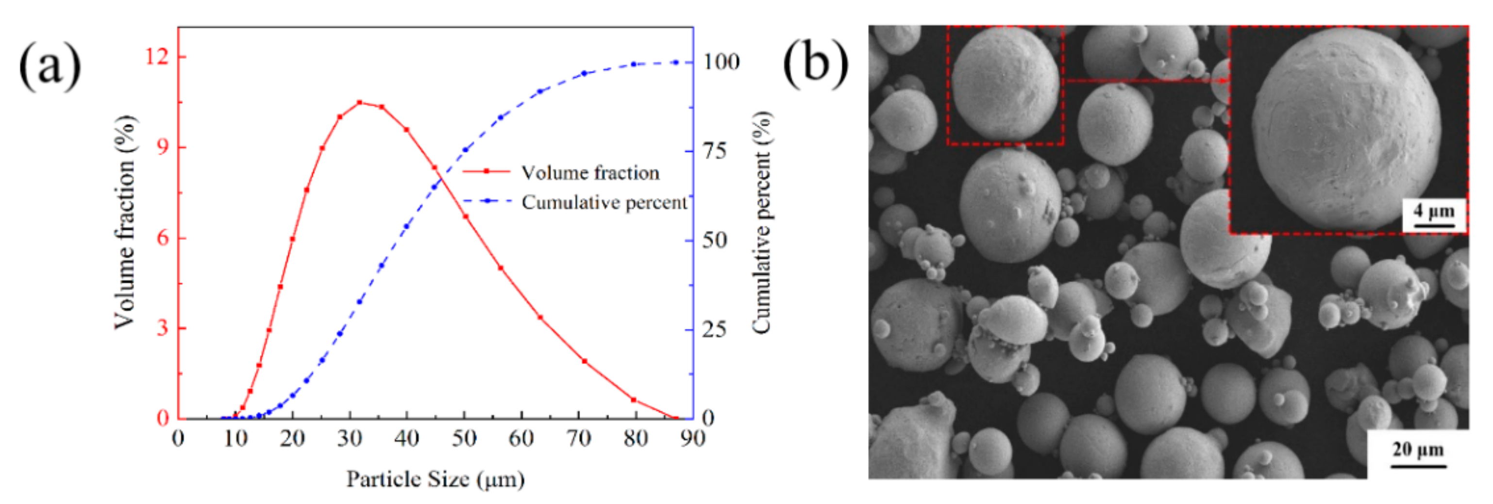
The materials are Cu–Cr–Zr alloy powders made by gas atomization, produced by Jiangsu Vilory Advanced Materials Technology Co., Ltd., Xuzhou, China, and the chemical compositions are listed in Table 1. The size of the virgin powder is measured by a laser particle size analyzer (Master sizer 3000, Malvern Instrument Ltd., Malvern, UK). As shown in Figure 1a, the particle size distribution of the powders exhibits a nearly normal distribution ranging from 15 μm to 53 μm with an average size of 36.8 μm, which is beneficial for improving the apparent density of the virgin powder. The scanning electron microscopy (SEM) image of the powders in Figure 1b shows a few satellite particles around the powders and most of the nearly spherical powders have good fluidity, which is conducive to the deposition of a homogeneous powder layer during the LPBF process. The specifications of 316L stainless steel substrate are 125 mm × 125 mm.

Table 1.
Chemical compositions of the virgin powder.
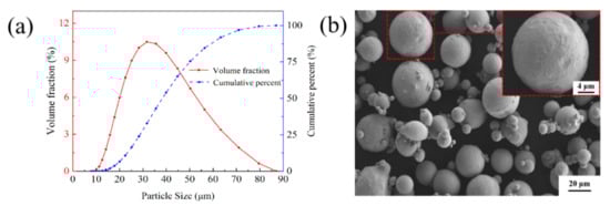
Figure 1.
(a) Size distribution and (b) SEM morphology of the virgin Cu-Cr-Zr powder.
A commercial selective laser melting (SLM) machine (HK-SLM 125, HUAKE 3D, Wuhan, China) is applied for specimen preparation, and the radiation source is a single-mode fiber laser with maximum output power of 500 W. The laser device has a single-mode continuous wave with a 1064 nm wavelength and an energy intensity of Gaussian profile. The system consists of an automatic powder delivery system, a building model and a computer system for multi-threaded control. The experiments are carried out in an argon atmosphere, and the concentration of O2 is controlled below 600 ppm. The scanning system adopts galvanometer type dynamic focusing, and the maximum scanning velocity is 8 m/s.
2.2. Experimental Methods
In order to effectively optimize the processing parameters, the deposition characteristics of LPBF are investigated from one-dimensional to three-dimensional [6,12,31]. First of all, the parameters listed in Table 2 are used to discuss the effect of the laser power and the scanning velocity on the surface topography of the single tracks fabricated by LPBF with a length of 10 mm. The surface morphologies are observed by a digital microscope with a magnification from 50× to 500×. The three typical track types and process map of single tracks are shown in Figure 2.
Table 2.
Parameters for the fabrication of the single tracks.
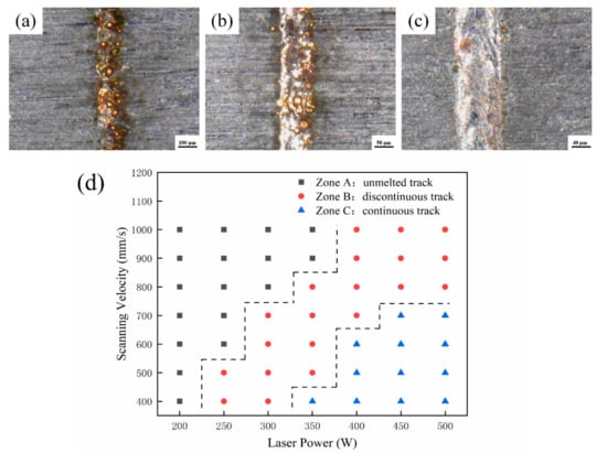
Figure 2.
Three typical track types of (a) unmelted track, (b) discontinuous track, (c) continuous track and (d) the process map of single tracks.
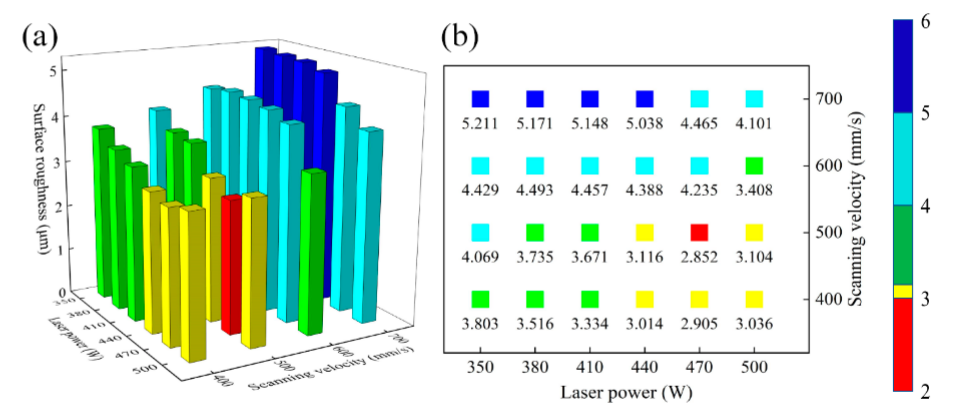
A two-dimensional plane is composed of many single tracks. Two adjacent single tracks contact each other to produce the overlap area and the remelting expansion area. The height between this area and the melting channel determines the quality of the overlap [32,33]. Therefore, the surface roughness can be used to evaluate the quality of single plane formed under different process parameters. The laser power and the scanning velocity range of the continuous single track are selected for the single plane forming experiments. The process parameters are listed in Table 3. The domestic JD 520 surface roughness measuring instrument is used to measure the surface roughness of the single plane under different process conditions. The scanning path of the probe is perpendicular to the direction of laser scanning. When laser power is 470 W and scanning velocity is 500 mm/s, the minimum surface roughness is 2.852 μm, and the value below the square indicates the surface roughness of the single plane in Figure 3.
Table 3.
Parameters used to produce the single planes.
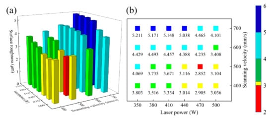
Figure 3.
(a) The relationship between laser power, scanning velocity and surface roughness of the single plane, (b) top view of (a).
During the LPBF process, the working chamber is filled with argon to ensure that the volume fraction of oxygen is less than 0.06%, and the substrate is preheated to 200 °C. Because the particle size of the virgin powder ranges from 15 μm to 53 μm, the thickness of powder spreading layer is set to 50 μm. In addition, Figure 4 indicates that alternate scanning with 67° interlaminar commutation can effectively alleviate the thermal stress concentration and reduce the possibility of deformation and warpage.
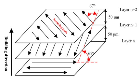
Figure 4.
The scanning strategy in LPBF process.
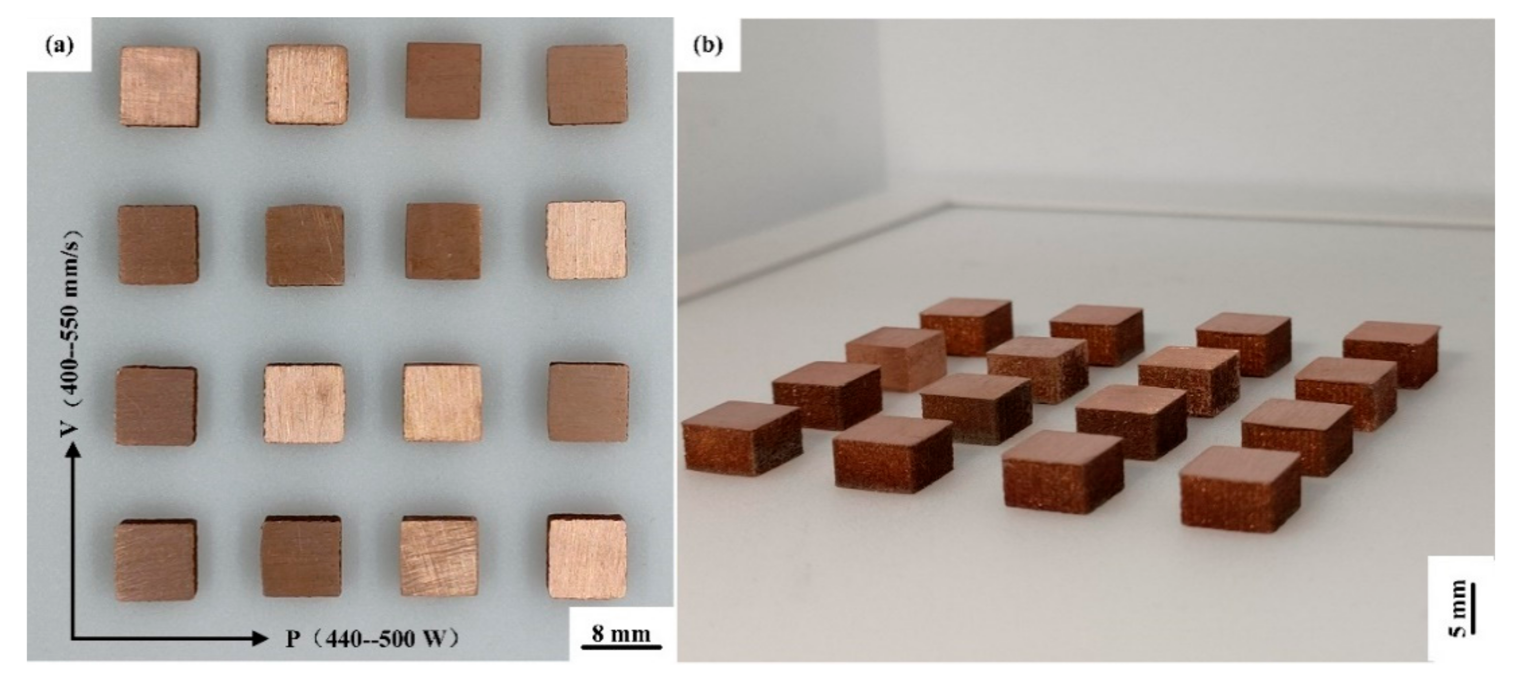
The expansion of the process parameters is listed in Table 4, when the surface roughness is the smallest. 16 sets of cuboid samples with a size of 8 mm × 8 mm × 5 mm are shown in Figure 5. To determine the maximum energy that the powder can absorb, the relationship between laser energy density (E, J/mm3) and laser power (P, W), scanning velocity (v, mm/s), scanning spacing (h, mm), and layer thickness (t, μm) is expressed as:
Table 4.
Parameters used to fabricate the cuboid samples.

Figure 5.
(a) Top view and (b) horizontal view of Cu–Cr–Zr alloy cuboid samples fabricated by LPBF.
After grinding and acetone cleaning, the relative density of the sample is measured with an electronic balance via Archimedes method, and the average value is measured five times. After the optimization of process parameters, it can be seen from Table 5 that the optimal relative density of the Cu–Cr–Zr alloy sample is 98.53%, when the laser power is 440 W and the scanning velocity is 450 mm/s.
Table 5.
Relative density and laser energy density of cuboid samples with different laser power and scanning velocity.
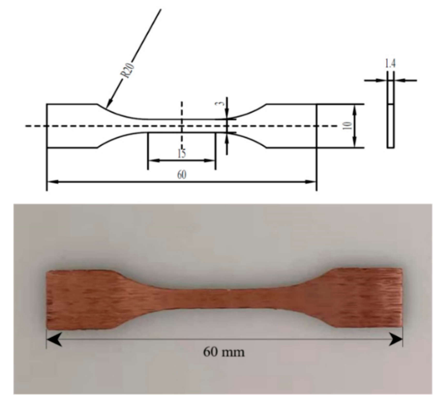
The microstructure is observed by an optical microscope (OM, Axiovert 200 MAT metallurgical microscope). The selected samples are treated by metallographic method, and then etched with a mixed solution of 1.5 g FeCl3, 10 mL HCl and 30 mL distilled H2O for 15 s. The distribution of elements, micromorphology and precipitates of LPBF Cu–Cr–Zr alloy samples are analyzed by a scanning electron microscope (SEM, FEI Nano SEM 450), equipped with energy dispersive spectrometry (EDS). Phase identification is tested by X-Ray Diffraction (XRD, Bruker AXS D2 PHASER) with Cu-Kα radiation at 30 kV and 10 mA. Microhardness tests are carried out with a 200 HV-5 microhardness tester at a load of 4.9 N and a holding time of 15 s. In order to adapt to the special fixture, the tensile specimens are designed according to the standard of Figure 6 and using a Zwick/Roell tester at a tensile rate of 2 mm/min under quasi-static loading to evaluate the tensile properties at room temperature. After rupture, the fracture morphologies are analyzed by SEM.
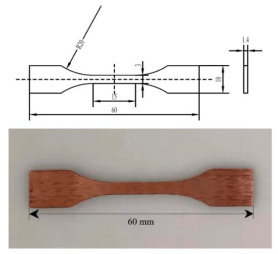
Figure 6.
Cu–Cr–Zr alloy tensile specimen fabricated by LPBF.
The LFA 427 laser thermal conductivity analyzer is used to measure the thermal conductivity of LPBF samples at different temperatures. Before the test, the upper and lower ends of the sample are polished and flattened into a square with a bottom surface of 10 × 10 mm or a cylinder with a diameter of 12.7 mm. The calculation formula for measuring thermal conductivity by laser flash method is shown as:
where λ is the thermal conductivity (W/(m·K)), Cp is the specific heat capacity (J/(kg·K)), α is the thermal diffusivity (m2/s), and ρ is the experimental density of sample (kg/m3).
Finally, the optimized parameters are used to manufacture two alloy heat sinks that combined the advantages of Cu–Cr–Zr alloy powder and LPBF technology. Subsequently, the experimental platform built as shown in Figure 7, and the heat dissipation performance is tested and compared. At the same time, the relationship between volume flow and heat transfer coefficient is explored.
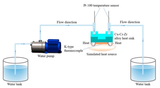
Figure 7.
Schematic diagram of the heat dissipation test of Cu–Cr–Zr alloy heat sink.
3. Results and Discussion
3.1. Parameter Study and Microstructure Characterization
After the one-dimensional to the three-dimensional optimization, Table 5 shows that the optimal relative density of sample 2 is 98.53%, but the corresponding laser energy density is between 133 J/mm3 of sample 4 and 208 J/mm3 of sample 13, which shows that the laser energy density and the relative density do not show a simple positive correlation.
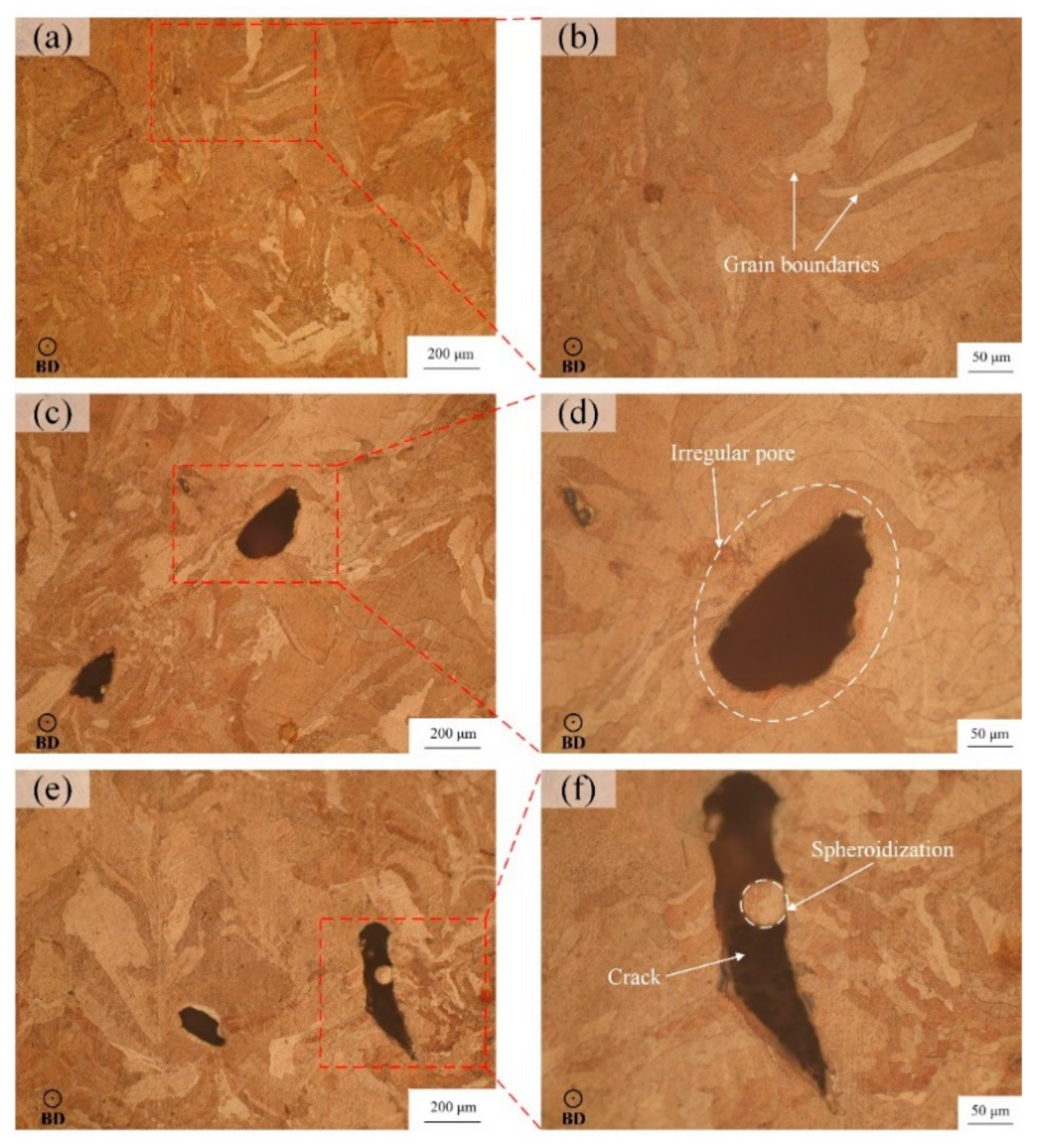
As shown in Figure 8a,b, the sample 2 is relatively dense under the optical microscope with fewer defects, and obvious grain boundaries can be seen after corrosion. In Figure 8c,d, due to the lower laser energy density, the gas between powder particles will not escape during the laser scanning, which will produce more pores. On the other hand, the low energy density is not enough to melt the powder completely, and the molten pool cannot be fully spread, which will form an irregular molten pool boundary, resulting in irregular pores which are clearly visible. In addition to the pores, there are also large cracks in Figure 8e. The reason for the cracks is that the high laser energy density leads to excessive stress intensity factors caused by the residual stress at a flaw or support structure. As a result, the cracks are generated in the solidification process of the molten pool and propagate along the melt channel, resulting in a decrease in the relative density of sample 13. After enlarging the crack area, Figure 8f shows that there is obvious spheroidization in the crack. This is because the temperature of molten pool is too high, which causes the metal droplets to boil and splash to other areas, solidify and shrink, and then form spheroidization, which leads to the drop in relative density [34].
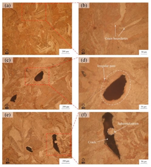
Figure 8.
Microscopic morphology of LPBF samples: (a,b) of sample 2 (P = 440 W, v = 450 mm/s, E = 163 J/mm3), (c,d) of sample 4 (P = 440 W, v = 550 mm/s, E = 133 J/mm3), (e,f) of sample 13 (P = 500 W, v = 400 mm/s, E = 208 J/mm3).
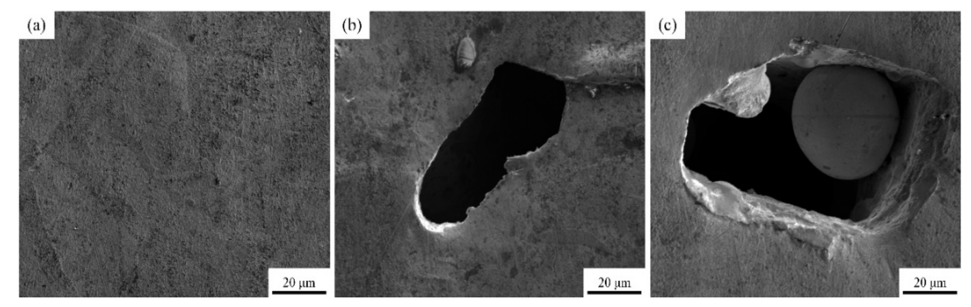
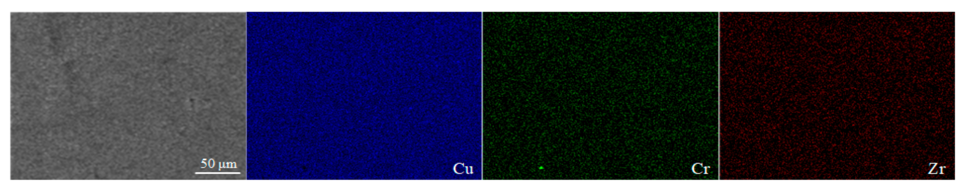
The surface morphology images of sample 2, sample 4 and sample 13 are shown in Figure 9 by SEM, respectively. The types of defect including pores, cracks and spheroidization are the same as those in Figure 8, and the formation mechanism and hazards have been analyzed accordingly. The EDS results of sample 2 shown in Figure 10 demonstrate that the elements of Cr and Zr are uniformly distributed in the Cu matrix, thereby indicating that fabricating Cu–Cr–Zr alloy by LPBF is a process of homogeneous deposition. However, the spheroidized particle area (about 40 μm in diameter) of sample 13 in Figure 9c has been performed by EDS scanning. The results show that the mass fractions of Cu and Cr are 98.75% and 1.25%, respectively, and no significant Zr is detected, indicating that Cr is slightly enriched in this spheroidized area.

Figure 9.
SEM images of the LPBF samples: (a–c) represent the surface morphology of the samples 2, 4, and 13, respectively.
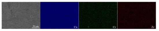
Figure 10.
Element distribution maps of the LPBF sample characterized by EDS.
3.2. Phase Identification and Precipitates
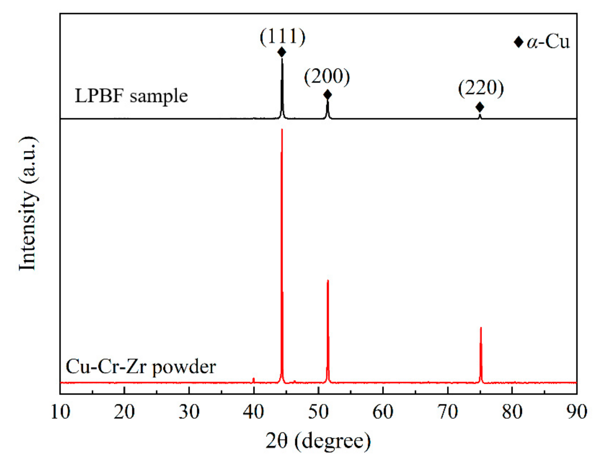
XRD patterns of the LPBF sample fabricated with optimal process parameters and the virgin powder are presented in Figure 11. It is evident that the main phase is α-Cu phase due to the detection limit of the XRD device. Interestingly, the intensity and distribution of Bragg peaks for the virgin powder are very close to those of the standard PDF card; a similar phenomenon has also been reported by Ma et al. [28]. For the LPBF sample, the Bragg peak with a crystal face index of (111) has the strongest intensity, which is consistent with the virgin powder. Moreover, the Bragg peak width of the LPBF sample is wider than that of the virgin powder, indicating that grain refinement occurs, which is caused by rapid cooling and solidification.

Figure 11.
XRD patterns of the LPBF sample fabricated with optimal parameters and the virgin powder.
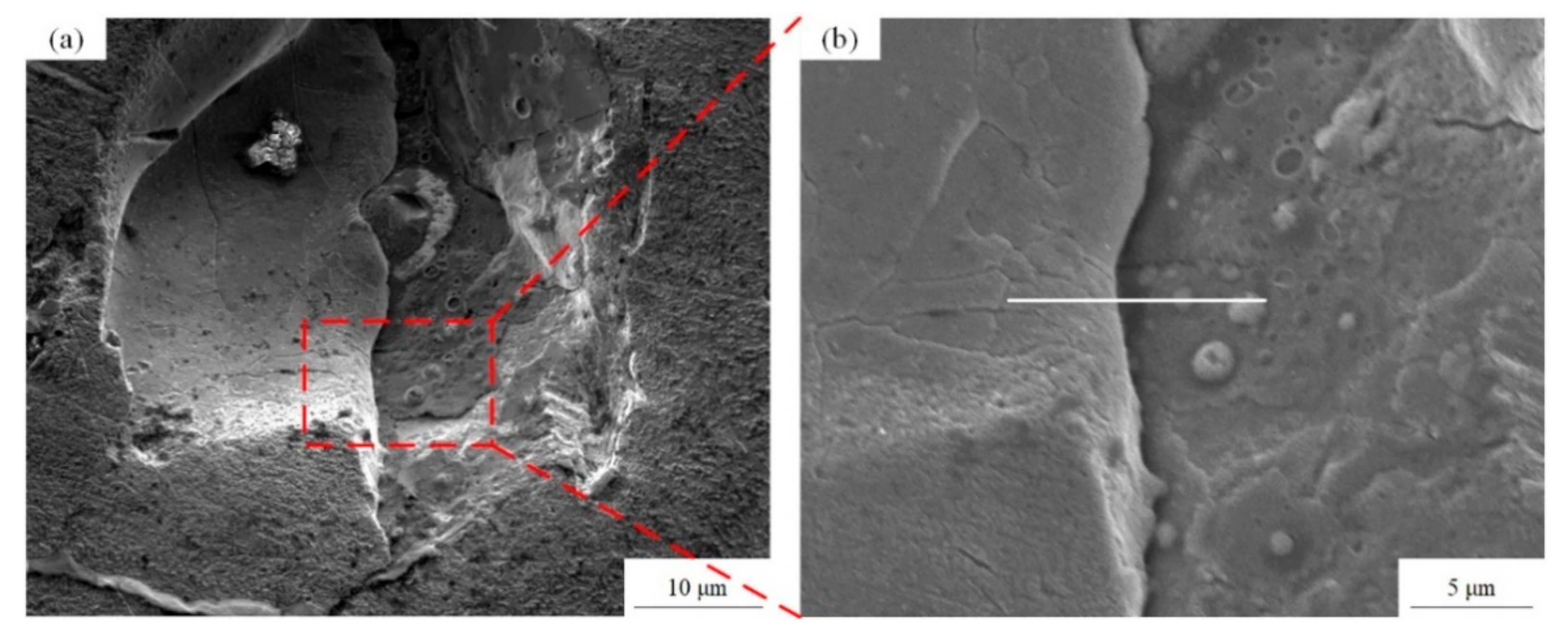
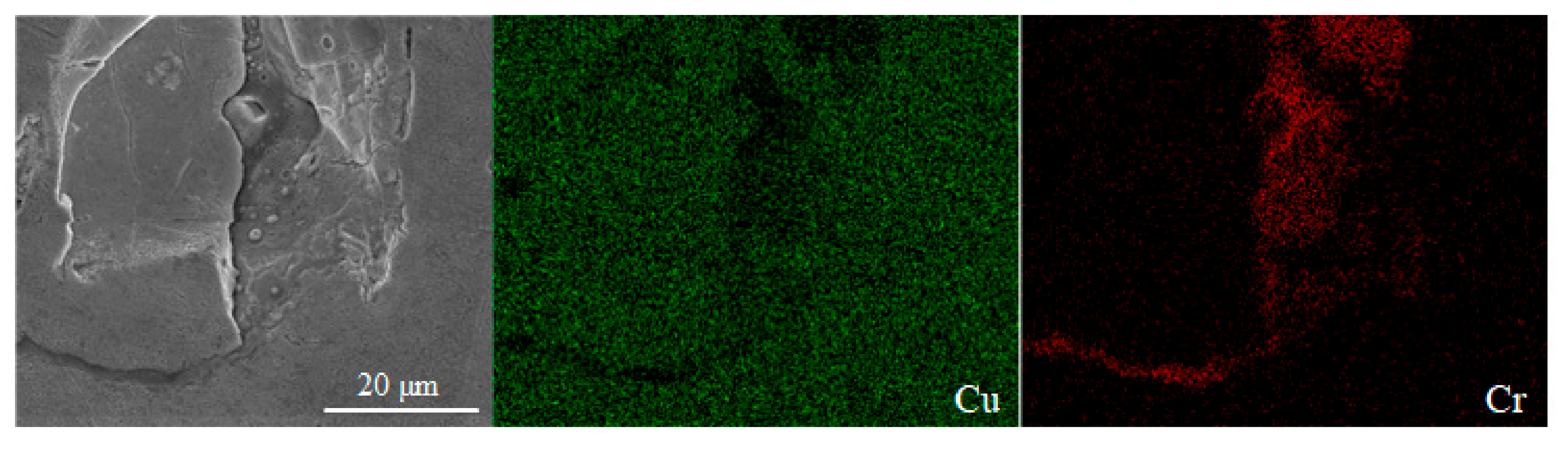
According to the Cu–Cr binary phase diagram [35], the eutectic reaction of Cu and Cr occurs at 1076.2 °C, and the highest solubility of Cr is 0.65 wt.%. The solubility of Cr decreases with the decrease of temperature, and Cr is almost insoluble in Cu at room temperature. Figure 12 shows the SEM images of the precipitates observed on the surface of the LPBF sample, in which a large number of fine spherical precipitates are about 1 μm in size. Continuously, the performance of the EDS surface scan is analyzed in Figure 12a, and it can be seen from Figure 13 that the segregation of Cr really occurs in this area. Furthermore, the EDS line scan analysis of Figure 12b shows that the Cr content fluctuates greatly during the scanning process, and the Cr is less than 10 wt.% at the initial stage of scanning, but Cr on the spherical precipitates is more than 40 wt.%, which indicates that Cr is enriched here, and the fine spherical particles are Cr precipitates. The formation of the Cr precipitates may be caused by the rapid solidification and the defects such as pores and cracks in Figure 12a. The constitutional supercooling occurs at the interface of the defect area, and solute redistribution appears during the non-equilibrium solidification process, which leads to the Cr segregation. The second reason may be the solubility limit of Cr in the copper matrix, which leads to the enrichment of Cr and the formation of a large number of fine precipitates.

Figure 12.
(a) The SEM images of the precipitates observed on the surface of LPBF sample and (b) the amplification view of the precipitates area.
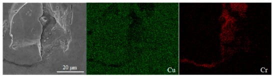
Figure 13.
Segregation of Cr appears in EDS surface scan analysis.
3.3. Mechanical Properties and Thermal Conductivity
Figure 14 shows the microhardness of the LPBF sample on the X–Y plane and Y–Z plane. In both directions, the fluctuation of the hardness value caused by the change of the test position is very small, indicating that the Cu–Cr–Zr alloy fabricated by LPBF has a uniform distribution. There is a certain difference between the average Vickers hardness of the X–Y plane (106.1 ± 1.1 HV) and the average Vickers hardness of the Y–Z plane (70.7 ± 1.3 HV), which suggests that there is anisotropy on the LPBF sample. In addition, the Vickers hardness of the LPBF Cu–Cr–Zr sample is higher than that of the LPBF Cu (84 ± 4.2 HV) and the wrought C11000 Cu (51.3 HV to 104 HV) reported by [36]. Grain refinement and microhardness enhancement are the combined effects of rapid solidification and Cr addition.
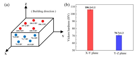
Figure 14.
(a) The microhardness test results and (b) the average Vickers hardness of X–Y plane and Y–Z plane.
The sample A (P = 500 W, v = 400 mm/s, ρ/ρ0 = 90.41%) reaches a UTS of 107 MPa and an elongation of 13.33%, and sample B (P = 440 W, v = 450 mm/s, ρ/ρ0 = 98.53%) reaches a UTS of 156 MPa and an elongation of 18.67%. Stress–strain curves of sample A and sample B at room temperature are shown in Figure 15a. The relative density of LPBF Cu–Cr–Zr alloy does have a certain effect on mechanical properties, and the results are consistent with the analysis of microstructure. In Figure 15b, the thermal conductivity of LPBF sample at room temperature is 124.96 ± 4.41 W/(m·K), and tends to be stable as temperature rises. When measuring temperature reaches 400 °C, the maximum thermal conductivity is 172.12 ± 1.61 W/(m·K). The thermal conductivity of the LPBF Cu–Cr–Zr sample measured at room temperature is lower than that of pure Cu, which may be caused by two factors. On the one hand, the addition of Cr and Zr will form solid solution in Cu matrix, and the foreign atoms will cause the lattice distortion, which will reduce the average free path of free electrons in the alloy, and thus decrease the thermal conductivity [30]. The solubility of Cr and Zr in Cu is limited, and their precipitates will also affect the thermal conductivity. On the other hand, the relative density of the alloy fabricated by LPBF technology is difficult to reach 100%, and the porosity and other defects in the alloy will also cause the decrease of thermal conductivity.
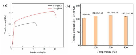
Figure 15.
(a) Stress–strain curves of sample A and sample B at room temperature and (b) the thermal conductivity of LPBF Cu–Cr–Zr alloy at different temperature.
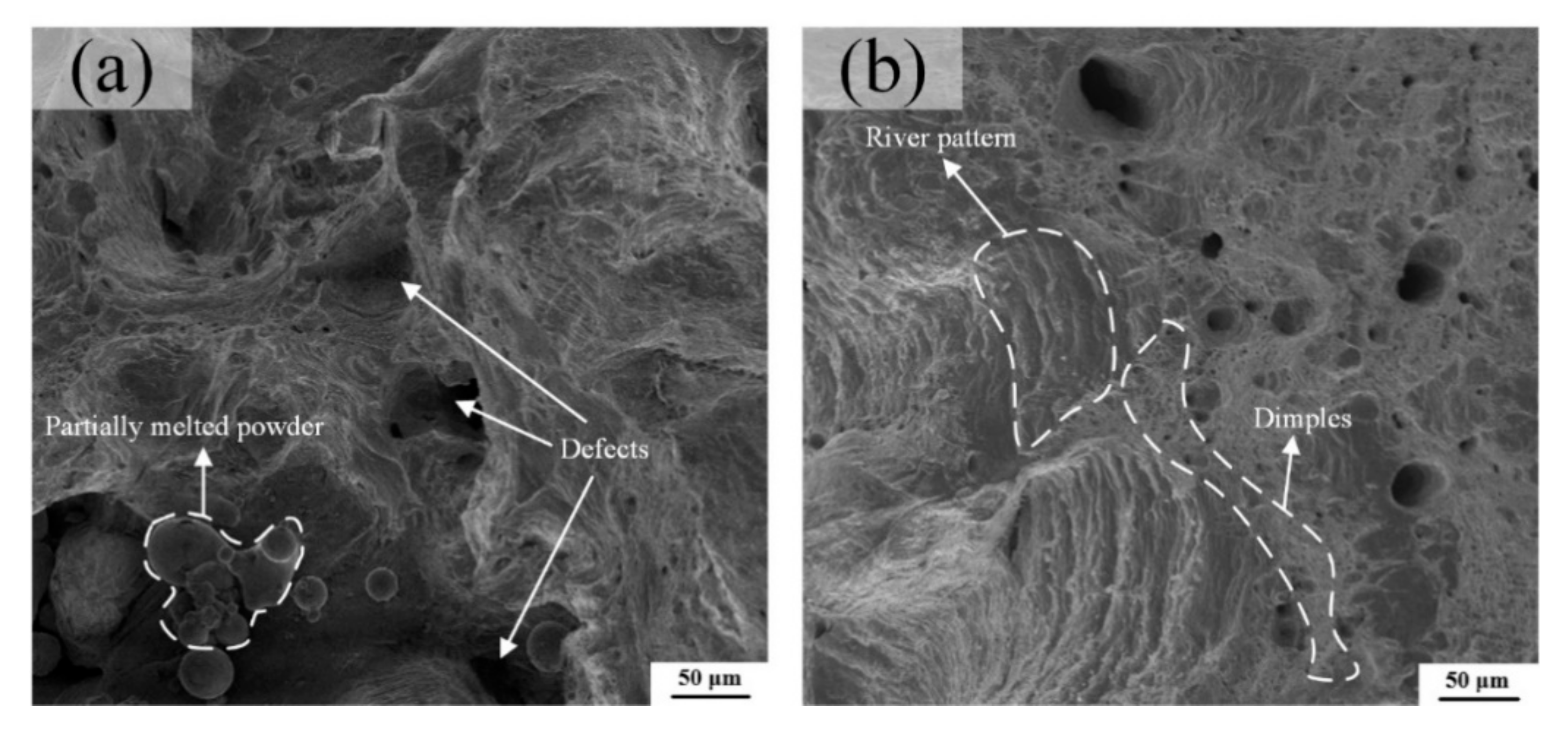
The tensile samples A and B have showed an obvious necking phenomenon in the macroscopic view, illustrating a ductile fracture feature. From the high magnification views exhibited in Figure 16a,b, the dimple-like and river-like features can be clearly observed on the fracture surface, which confirms that the fracture mode of LPBF Cu–Cr–Zr alloy is not a single, but a mixed ductile-brittle mode, although Figure 16a possesses many partially melted powders and defects, which are caused by the high laser energy density of E = 208 J/mm3 as listed in Table 5, and the results are consistent with the analysis of microstructure. The number and size of the dimples are positively correlated with the energy absorbed during their formation, and the corresponding plastic deformation changes are obvious during the fracture process, showing the greater toughness of materials. In general, these can also explain that the sample A has a lower elongation than sample B.

Figure 16.
Tensile fracture morphology of (a) the sample A and (b) the sample B at room temperature.
3.4. The Heat Transfer Performance of Two Heat Sinks
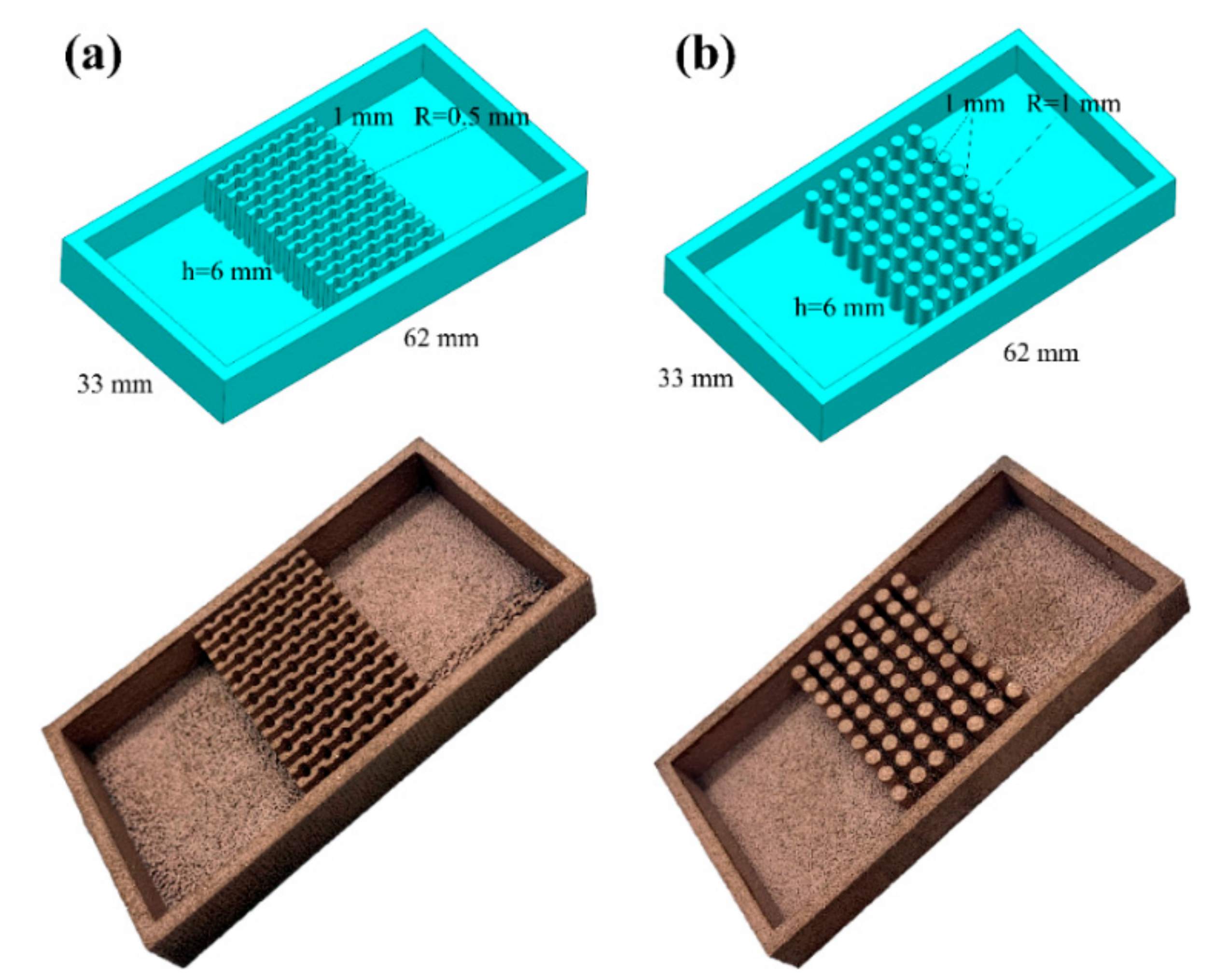
The optimized LPBF parameters are applied to fabricate two types of copper alloy heat sinks, the parallel fin heat sink with the fan-shaped cavity and the cylindrical micro-needle heat sink as selected, exhibited in Figure 17. The dimensions of the two heat sinks are exactly the same, but the structure of internal heat sink is different.
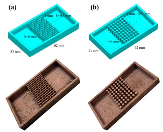
Figure 17.
Partial UG model and physical image of (a) the parallel fin heat sink with the fan-shaped cavity and (b) the cylindrical micro-needle heat sink.
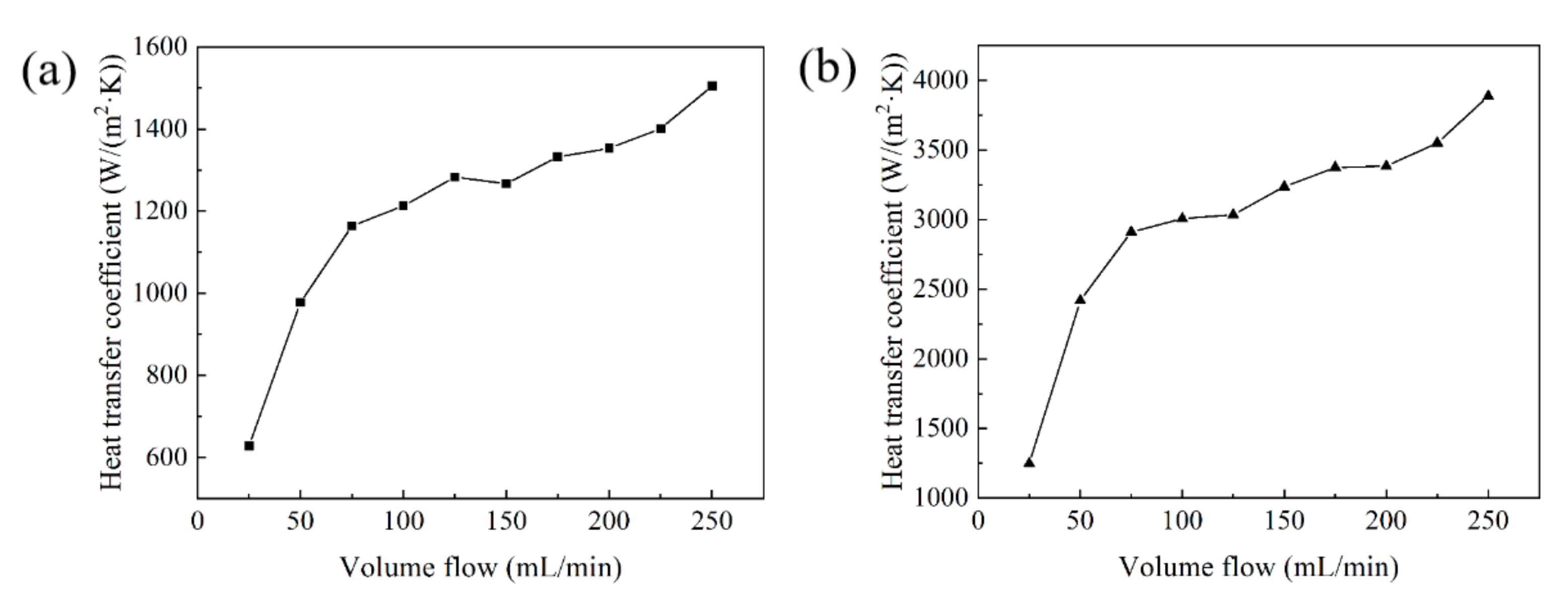
Based on the experimental platform in Figure 7, the heat dissipation effects of two Cu–Cr–Zr alloy heat sinks have been tested and compared. The relationship between the volume flow and the heat transfer coefficient of the two types of heat sink are shown in Figure 18. When the volume flow is 250 mL/min, the maximum heat transfer coefficient of the parallel fin heat sink with fan-shaped cavity is 1505 W/(m2·K) shown in Figure 18a, whereas the maximum heat transfer coefficient of the cylindrical micro-needle heat sink is 3887 W/(m2·K) shown in Figure 18b. The heat transfer coefficients of the two heat sinks are positively correlated with the volume flow. Under the condition of a certain volume flow, the heat transfer coefficient of the cylindrical micro-needle heat sink is always higher than that of the parallel fin heat sink with fan-shaped cavity. Therefore, the heat dissipation performance of the cylindrical micro-needle heat exchanger is better.
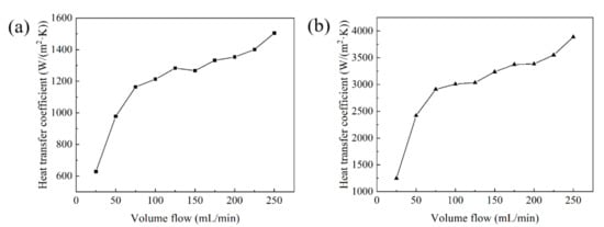
Figure 18.
The relationship between the volume flow and the heat transfer coefficient of (a) the parallel fin heat sink with fan-shaped cavity and (b) the cylindrical micro-needle heat sink.
4. Conclusions
For the integration requirements of heat dissipation materials and structures in the electronic field, the Cu–Cr–Zr alloy with a relative density of 98.53% is successfully prepared by LPBF. The process parameters of Cu–Cr–Zr alloy fabricated by LPBF have been optimized. The following conclusions are summarized:
- (1)
- The laser energy density will affect the forming quality of Cu–Cr–Zr alloy. When the laser energy density is 163 J/mm3, fewer defects on the surface of the LPBF sample are observed. The optimal process parameter set of Cu–Cr–Zr alloy fabricated by LPBF is predicted as P = 440 W, v = 450 mm/s, h = 0.12 mm, t = 0.5 μm and the resultant sample exhibits a high relative density of 98.53%.
- (2)
- The α-Cu is the main phase of the LPBF sample, and the Bragg peak with a crystal face index of (111) has the strongest intensity. There is Cr enrichment in some areas, and the precipitates on the surface of the LPBF sample are observed as Cr spherical precipitates with a size of about 1 μm.
- (3)
- The tensile specimen manufactured with the optimal parameters reaches a UTS of 156 MPa and an elongation of 18.67% at room temperature. The dimple-like and river-like features are simultaneously observed on the fracture surface, and the fracture mode is a mixed ductile-brittle mode. The difference in Vickers hardness between 106.1 ± 1.1 HV of X-Y plane and 70.7 ± 1.3 HV of Y-Z plane reflects the anisotropy of the LPBF sample.
- (4)
- When the volume flow is 250 mL/min, the maximum heat transfer coefficients of the parallel fin heat sink with the fan-shaped cavity and the cylindrical micro-needle heat sink are 1505 W/(m2·K) and 3887 W/(m2·K), respectively. The heat transfer coefficients are positively correlated with the volume flow, and the heat transfer coefficient of the cylindrical micro-needle heat sink is always higher than that of the parallel fin heat sink with the fan-shaped cavity with certain volume flow.
Author Contributions
Conceptualization, X.F. and W.X.; methodology, X.F. and W.G.; writing-original draft, X.F. and W.X.; formal analysis, X.F., W.L. and W.G.; investigation, W.X., Q.W., Y.W. and W.L.; writing-review and editing, Q.W. and Y.W.; validation, Q.W. All authors have read and agreed to the published version of the manuscript.
Funding
This work was funded by the National Nature Science Foundation of China, grant number 51775207 and the Applied Basic Research Programs of Wuhan City, grant number 2017010201010125.
Institutional Review Board Statement
Not applicable.
Informed Consent Statement
Not applicable.
Data Availability Statement
Not applicable.
Acknowledgments
The authors would like to gratefully acknowledge the technical supports from the State Key Laboratory of Materials Processing and Die & Mould Technology in HUST. Authors also appreciate the Analytical and Testing Center in HUST and the Center for Nanoscale Characterization and Devices, Wuhan National Laboratory for Optoelectronics (WNLO) for the analytical and testing services.
Conflicts of Interest
The authors declare no conflict of interest.
References
- Tenwick, M.J.; Davies, H.A. Enhanced strength in high conductivity copper alloy. Mater. Sci. Eng. 1988, 98, 543–546. [Google Scholar] [CrossRef]
- Xia, C.D.; Jia, Y.L.; Zhang, W.; Zhang, K.; Dong, Q.Y.; Xu, G.Y.; Wang, M.P. Study of deformation and aging behaviors of a hot rolled-quenched Cu-Cr-Zr-Mg-Si alloy during thermomechanical treatments. Mater. Des. 2012, 39, 404–409. [Google Scholar] [CrossRef]
- Meng, Y.F.; Zhang, J.P.; Duan, C.Y.; Chen, C.; Feng, X.M.; Shen, Y.F. Microstructures and properties of W-Cu functionally graded composite coatings on copper substrate via high-energy mechanical alloying. Adv. Powder Technol. 2015, 26, 392–400. [Google Scholar] [CrossRef]
- Scudino, S.; Eckert, J.; Yang, X.Y.; Sordelet, D.J.; Schultz, L. Conditions for quasicrystal formation from mechanically alloyed Zr-based glassy powders. Intermetallics 2007, 15, 571–582. [Google Scholar] [CrossRef]
- Popovich, A.; Sufiiarov, V.; Polozov, I.; Borisov, E.; Masaylo, D.; Orlov, A. Microstructure and mechanical properties of additive manufactured copper alloy. Mater. Lett. 2016, 179, 38–41. [Google Scholar] [CrossRef]
- Gunasekaran, J.; Sevvel, P.; Solomon, I.J. Metallic materials fabrication by selective laser melting: A review. Mater. Today Proc. 2021, 37, 252–256. [Google Scholar] [CrossRef]
- Torres-Carrillo, S.; Siller, H.R.; Vila, C.; Lopez, C.; Rodriguez, C.A. Environmental analysis of selective laser melting in the manufacturing of aeronautical turbine blades. J. Clean. Prod. 2020, 246, 19068–119081. [Google Scholar] [CrossRef]
- Hwang, T.W.; Kang, N.; Vantyne, C.J.; Kim, Y.T.; Lee, T.; Moon, Y.H. Microforming of fine metallic rods by the selective laser melting of powder. Addit. Manuf. 2020, 36, 101612–101624. [Google Scholar] [CrossRef]
- Farber, E.; Nazarov, D.; Mitrofanov, I.; Sufiiarov, V.; Popovich, A.; Maximov, M. Development of the titanium meshes by selective laser melting and chemical etching for using as medical implants. Mater. Today Proc. 2020, 30, 746–751. [Google Scholar] [CrossRef]
- Wang, D.; Wang, Y.M.; Yang, Y.Q.; Lu, J.B.; Xu, Z.L.; Li, S.; Lin, K.J.; Zhang, D.Y. Research on design optimization and manufacturing of coating pipes for automobile seal based on selective laser melting. J. Mater. Process. Technol. 2019, 273, 116227–116236. [Google Scholar] [CrossRef]
- Huang, Y.C.; Hsu, H.C. Selective Laser Melting Heat Sinks under Jet Impingement Cooling for Heat Dissipation of Higher Light Output LED Lighting in a Limited Space. Appl. Sci. 2020, 10, 3898. [Google Scholar] [CrossRef]
- Prashanth, K.G. Selective Laser Melting: Materials and Applications. J. Manuf. Mater. Process. 2020, 4, 13. [Google Scholar] [CrossRef] [Green Version]
- Lykov, P.A.; Safonov, E.V.; Akhmedianov, A.M. Selective laser melting of copper. Mater. Sci. Forum 2016, 4255, 284–288. [Google Scholar] [CrossRef]
- Ikeshoji, T.T.; Nakamura, K.; Yonehara, M.; Imai, K.; Kyogoku, H. Selective laser melting of pure copper. JOM 2018, 70, 396–400. [Google Scholar] [CrossRef]
- Colopi, M.; Caprio, L.; Demir, A.G.; Previtali, B. Selective laser melting of pure Cu with a 1 kW single mode fiber laser. Procedia CIRP 2018, 74, 59–63. [Google Scholar] [CrossRef]
- Colopi, M.; Demir, A.G.; Caprio, L.; Previtali, B. Limits and solutions in processing pure Cu via selective laser melting using a high-power single-mode fiber laser. Int. J. Adv. Manuf. Technol. 2019, 104, 2473–2486. [Google Scholar] [CrossRef]
- Jadhav, S.D.; Dadbakhsh, S.; Goossens, L.; Kruth, J.P.; Van Humbeeck, J.; Vanmeensel, K. Influence of selective laser melting process parameters on texture evolution in pure copper. J. Mater. Process. Technol. 2019, 270, 47–58. [Google Scholar] [CrossRef]
- Tran, T.Q.; Chinnappan, A.; Lee, J.K.Y.; Loc, N.H.; Tran, L.T.; Wang, G.J.; Kumar, V.V.; Jayathilaka, W.A.D.M.; Ji, D.X.; Doddamani, M.; et al. 3D Printing of Highly Pure Copper. Metals 2019, 9, 756. [Google Scholar] [CrossRef] [Green Version]
- Scudino, S.; Unterdoerfer, C.; Prashanth, K.G.; Attar, H.; Ellendt, N.; Uhlenwinkel, V.; Eckert, J. Additive manufacturing of Cu-10Sn bronze. Mater. Lett. 2015, 156, 202–204. [Google Scholar] [CrossRef]
- Deng, C.Y.; Kang, J.W.; Feng, T.; Feng, Y.L.; Wang, X.; Wu, P.Y. Study on the selective laser melting of CuSn10 powder. Materials 2018, 11, 614. [Google Scholar] [CrossRef] [Green Version]
- Ventura, A.P.; Wade, C.A.; Pawlikowski, G.; Bayes, M.; Watanabe, M.; Misiolek, W.Z. Mechanical properties and microstructural characterization of Cu-4.3 Pct Sn fabricated by selective laser melting. Metall. Mater. Trans. A 2017, 48, 178–187. [Google Scholar] [CrossRef]
- Mao, Z.F.; Zhang, D.Z.; Wei, P.T.; Zhang, K.F. Manufacturing feasibility and forming properties of Cu-4Sn in selective laser melting. Materials 2017, 10, 333. [Google Scholar] [CrossRef] [Green Version]
- Mao, Z.F.; Zhang, D.Z.; Jiang, J.J.; Fu, G.; Zhang, P. Processing optimisation, mechanical properties and microstructural evolution during selective laser melting of Cu-15Sn high-tin bronze. Mater. Sci. Eng. A 2018, 721, 125–134. [Google Scholar] [CrossRef] [Green Version]
- Gustmann, T.; Neves, A.; Kuhn, U.; Gargarella, P.; Kiminami, C.S.; Bolfarini, C.; Eckerta, J.; Paulya, S. Influence of processing parameters on the fabrication of a Cu-Al-Ni-Mn shape-memory alloy by selective laser melting. Addit. Manuf. 2016, 11, 23–31. [Google Scholar] [CrossRef]
- Gustmann, T.; dos Santos, J.M.; Gargarella, P.; Kuhn, U.; Van Humbeeck, J.; Pauly, S. Properties of Cu-based shape-memory alloys prepared by selective laser melting. Shap. Mem. Superelast. 2017, 3, 24–36. [Google Scholar] [CrossRef] [Green Version]
- Tian, J.; Zhu, W.Z.; Wei, Q.S.; Wen, S.F.; Li, S.; Song, B.; Shi, Y.S. Process optimization, microstructures and mechanical properties of a Cu-based shape memory alloy fabricated by selective laser melting. J. Alloy. Compd. 2019, 785, 754–764. [Google Scholar] [CrossRef]
- Zhang, S.S.; Zhu, H.H.; Hu, Z.H.; Zeng, X.Y.; Zhong, F. Selective laser melting of Cu-10Zn alloy powder using high laser power. Powder Technol. 2019, 342, 613–620. [Google Scholar] [CrossRef]
- Ma, Z.B.; Zhang, K.F.; Ren, Z.H.; Zhang, D.Z.; Tao, G.B.; Xu, H.S. Selective laser melting of Cu–Cr–Zr copper alloy: Parameter optimization, microstructure and mechanical properties. J. Alloy. Compd. 2020, 828, 154350–154359. [Google Scholar] [CrossRef]
- Ma, Z.B.; Zhang, D.Z.; Liu, F.; Jiang, J.J.; Zhao, M.; Zhang, T. Lattice structures of Cu-Cr-Zr copper alloy by selective laser melting: Microstructures, mechanical properties and energy absorption. Mater. Des. 2020, 187, 108406–108417. [Google Scholar] [CrossRef]
- Wallis, C.; Buchmayr, B. Effect of heat treatments on microstructure and properties of CuCrZr produced by laser-powder bed fusion. Mater. Sci. Eng. A 2019, 744, 215–223. [Google Scholar] [CrossRef]
- Yap, C.Y.; Chua, C.K.; Dong, Z.L.; Liu, Z.H.; Zhang, D.Q.; Loh, L.E.; Sing, S.L. Review of selective laser melting: Materials and applications. Appl. Phys. Rev. 2015, 2, 041101–041121. [Google Scholar] [CrossRef]
- Cerit, E.; Lazoglu, I. A CAM-based path generation method for rapid prototyping applications. Int. J. Adv. Manuf. Technol. 2011, 56, 319–327. [Google Scholar] [CrossRef]
- Pupo, Y.; Delgado, J.; Sereno, L.; Ciurana, J. Scanning Space Analysis in Selective Laser Melting for CoCrMo Powder. Procedia Eng. 2013, 63, 370–378. [Google Scholar] [CrossRef] [Green Version]
- Li, R.D.; Shi, Y.S.; Wang, Z.G.; Wang, L.; Liu, J.H.; Jiang, W. Densification behavior of gas and water atomized 316L stainless steel powder during selective laser melting. Appl. Surf. Sci. 2010, 256, 4350–4356. [Google Scholar] [CrossRef]
- Liu, Y.L.; Liu, S.H.; Zhang, C.; Du, Y.; Wang, J.; Li, Y.W. Experimental Investigation and Thermodynamic Description of the Cu-Zr System. J. Phase Equilib. Diff. 2017, 38, 1–14. [Google Scholar] [CrossRef]
- Yan, X.C.; Chang, C.; Dong, D.D.; Gao, S.H.; Ma, W.Y.; Liu, M.; Liao, H.L.; Yin, S. Microstructure and mechanical properties of pure copper manufactured by selective laser melting. Mater. Sci. Eng. A 2020, 789, 139615–139625. [Google Scholar] [CrossRef]


Publisher’s Note: MDPI stays neutral with regard to jurisdictional claims in published maps and institutional affiliations. |
© 2021 by the authors. Licensee MDPI, Basel, Switzerland. This article is an open access article distributed under the terms and conditions of the Creative Commons Attribution (CC BY) license (https://creativecommons.org/licenses/by/4.0/).