Article

Study of Coatings Formed on Zirconium Alloy by Plasma Electrolytic Oxidation in Electrolyte with Submicron Yttria Powder Additives

1
Moscow Aviation Institute, National Research University, 121552 Moscow, Russia
2
Department of Nanotechnology, Keldysh Research Center, 125438 Moscow, Russia
3
Laboratory of Oxidation and Passivation of Metals and Alloys, Institute of Physical Chemistry and Electrochemistry of RAS, 119991 Moscow, Russia
4
Spark Plasma Sintering Laboratory, Moscow State University of Technology “STANKIN”, 127994 Moscow, Russia
*
Author to whom correspondence should be addressed.
Metals 2021, 11(9), 1392; https://doi.org/10.3390/met11091392
Submission received: 12 August 2021 / Revised: 24 August 2021 / Accepted: 30 August 2021 / Published: 1 September 2021
(This article belongs to the Section Corrosion and Protection)

Abstract

:
Coatings with thickness 40 to 150 μm were formed by plasma electrolytic oxidation (PEO) on the zirconium alloy Zr-1Nb (Zr-1% Nb) in the slurry electrolyte containing 9 g/L Na2SiO3 5H2O, 5 g/L Na(PH2O2) and 6 g/L submicron Y2O3 yttria powder during 60 min under the AC electrical mode at current densities 20; 30 and 40 A/dm2. The surface morphology, structure, composition, and corrosion-protective ability of the formed coatings have been analyzed. At PEO current density 30 A/dm2, a predominantly tetragonal phase of zirconia was formed in coatings. Increasing the PEO current density up to 40 A/dm2 promoted the formation of the coating surface layer containing submicron yttria particles. Electrochemical polarization studies in 0.5% LiOH solution showed that PEO coatings demonstrated high corrosion-protective ability. The dependence of the polarization currents on the PEO current density was found to be inconsequential.

1. Introduction

In the nuclear power industry, the actual problem is to ensure the safety of reactor facilities operation even with a significant increase in the temperature of the fuel elements cladding made of zirconium alloys [1]. This need became especially urgent after the accident at the Fukushima nuclear power plant in Japan. One of the methods for solving this problem is developing protective coatings for zirconium claddings [2,3]. Such coatings have to protect zirconium alloys from electrochemical and gas corrosion, absorption of oxygen and hydrogen in aggressive water-chemical environments and embrittlement. As methods of such protective coatings production, thermal spraying, physical vapor deposition, and chemical vapor deposition methods are most often used. Many studies in this area are associated with the deposition of metal coatings [4,5,6,7,8,9]. High efficiency is also shown by cermet multilayer coatings [10,11,12,13,14,15]. However, there are many limitations. So, when using metal layers, there is a risk of eutectics formation, such as zirconium-chromium at a temperature of 1332 °C, which leads to the degradation of the protective properties of the coatings. It was shown in [16] that for adequate protection the thickness of the ceramic layers should be at least 10 μm. During the coating’s formation process, such a thermal regime must be used to prevent the phase transformation of α-Zr to β-Zr at a temperature of 863 °C.
A promising method of plasma electrolytic oxidation (PEO) makes it possible to form multifunctional protective coatings [17,18,19,20,21] and has recently been increasingly used for zirconium alloys protection. The thickness of PEO coatings can reach 300 microns, while they are characterized by a layered structure. A thin transition barrier layer at the interface with the metal base is responsible for corrosion-protective properties, and the main working layer has high microhardness and wear resistance. The presence of a barrier layer chemically bonding the substrate and the coating is a significant advantage since it provides a high adhesion strength of the PEO coating to the metal base [22]. The use of plasma electrolytic oxidation for modification of zirconium alloys surfaces is promising, including economic and environmental advantages [23]. The thickness, composition and structure of the formed coatings depend on the parameters of the PEO mode (frequency, amplitude and shape of voltage pulses, anode and cathode current densities, duration of treatment), composition and temperature of the electrolyte. The individual components of the electrolyte and the products of their thermolysis can be incorporated into the PEO coating to form their insoluble oxides and various compounds with the products of metal base oxidation.
Recently, the number of works devoted to studying the corrosion-protective ability of PEO coatings on zirconium alloys, including for the protection of the fuel elements cladding, has significantly increased. The corrosion-protective ability of PEO coatings ~6 μm thick, formed in a silicate-alkaline electrolyte on the Zr-2.5Nb alloy (Zr-2.5% Nb), was studied in 0.125% lithium hydroxide LiOH, which was the model corrosive solution for the zirconium alloy [24]. It was shown that PEO treatment reduced corrosion currents by two orders of magnitude, including the tests in an autoclave at temperature 300 °C and pressure 10 MPa. In [25], PEO coatings on the Zircaloy-2 alloy (Zr-1.3% Sn) formed in silicate and aluminate electrolytes were studied. It was shown that formation in aluminate electrolyte of zirconia tetragonal phase t-ZrO2 in the coating provides higher wear resistance and leads to less cracking during the PEO treatment. It was shown in [26] that for the Zr-1Nb alloy (Zr-1% Nb) after PEO treatment in a phosphate electrolyte, the corrosion current in 0.125% LiOH solution decreases by about three orders of magnitude. The formed coatings contained monoclinic m-ZrO2 and tetragonal t-ZrO2 zirconia phases with a predominance of the monoclinic phase. In studies of the coatings formed in the silicate-alkaline electrolyte, it was noted that their corrosion-protective ability in a NaCl solution increased with an increase in the duration of PEO treatment to 10 min, but then decreased, which may be associated with increasing porosity [27]. In this case, the coatings predominantly contained the m-ZrO2 phase, and the content of the t-ZrO2 phase increased with increasing silicate content in the electrolyte. It was shown in [28] that PEO treatment of the Zr-702 alloy (Zr-1.8% Hf) for 3, 5, and 90 min improved both its wear resistance and corrosion resistance in 3.5% NaCl and 10% HCl. Simultaneously, it was noted that a reduction in the duration of PEO treatment led to increasing of corrosion resistance in 10% HCl, while corrosion currents in 3.5% NaCl were similar. In [29], PEO coatings were formed on the Zircaloy-4 alloy (Zr-1.5% Sn) in silicate, phosphate, pyrophosphate electrolytes and their combinations. The samples with coatings formed in the pyrophosphate and silicate-pyrophosphate electrolytes showed the highest corrosion resistance. In [30], the electrochemical behavior in 0.25% LiOH of PEO coatings formed on the Zr-1Nb alloy for 10 min in silicate-alkaline, pyrophosphate-alkaline, and silicate-pyrophosphate-alkaline electrolytes was compared. All coatings increased the corrosion resistance of the alloy by more than an order of magnitude. The smallest currents of corrosion and passivation were noted for coatings formed in a silicate-pyrophosphate-alkaline electrolyte. In [31], the effect of the voltage pulse frequency during PEO on the characteristics of coatings formed on zirconium for 10 min was investigated. Increasing the frequency led to decreasing porosity and corrosion currents, which were explained by a more uniform distribution of microdischarges over the being-treated surface during PEO. The appearance of the t-ZrO2 phase in the coating was also noted. In [32], the possibility of the oxidation resistance improvement of the Zr-4 alloy (Zr-1.4% Sn) in the environment of superheated water vapor with a temperature of 1000 °C was investigated. Two-layer coating consisting of the PEO layer formed on the alloy for 20 min in aluminate-phosphate-alkaline electrolyte and the layer of FeCrAl deposited on it were studied. When using a single-layer FeCrAl coating, the inner oxide layer of ZrO2 was formed due to the mutual diffusion of zirconium and oxygen, which led to the destruction of the coating. For two-layer coating, no such defects were observed.
In recent years, a significant number of papers devoted to improving the characteristics of coatings on zirconium and its alloys by incorporating fine particles into their structure from slurry electrolytes during PEO treatment have been published [33,34,35,36]. So, additions to the alkaline electrolyte of such oxides nanoparticles as Al2O3, ZrO2, and CeO2 during the formation of PEO coatings on zirconium promote increasing in their corrosion-protective ability in 3.5% NaCl. When adding CeO2 nanoparticles to electrolytes, the corrosion currents for PEO coated samples decreased by four orders of magnitude compared to untreated zirconium [33]. Moreover, the addition of cerium dioxide and alumina nanoparticles in electrolytes promoted the formation of the t-ZrO2 phase in PEO coatings. In [34], the effect of graphite particles size introduced in the slurry electrolyte on the characteristics of PEO coatings was studied. The nanopowder addition leads to decreasing the friction coefficient and improvement in the hydrophobic properties of PEO coatings on zirconium. The addition of graphite nanoparticles in the electrolyte reduced the corrosion currents in 0.25% LiOH by four orders of magnitude and the addition of micron-sized graphite particles by three orders of magnitude. The PEO coating formed in the electrolyte without additives reduced the corrosion current by two orders of magnitude in comparison with untreated zirconium. In [35,36], the possibility of zirconia high-temperature phases (tetragonal t-ZrO2 and cubic c-ZrO2) stabilizing in PEO coatings by introducing additives of yttria nanoparticles in electrolytes was investigated. In [37,38], high thermal shock resistance and good thermal barrier properties of PEO coatings on zirconium and its alloys were noted. In [39], it was found that after 20–30 min of the PEO process, the quantity of small microdischarges on being treated zirconium surface significantly decreases, while that of large ones increases.
In most of the papers devoted to improving the characteristics of PEO coatings on zirconium and its alloys, nanopowders were used as additives in slurry electrolytes. In the scientific literature, there are no papers devoted to studying PEO coatings formed in slurry electrolytes with submicron powders additives. Unlike nanopowders, the use of submicron powders does not require additional operations and equipment for their dispersion, as a result of which they are less expensive and scarce. This work aimed to study the surface morphology, structure, composition, and corrosion-protective ability of coatings formed on the Zr-1Nb alloy by plasma electrolytic oxidation at different current densities in the slurry electrolyte with the addition of submicron yttria powder.

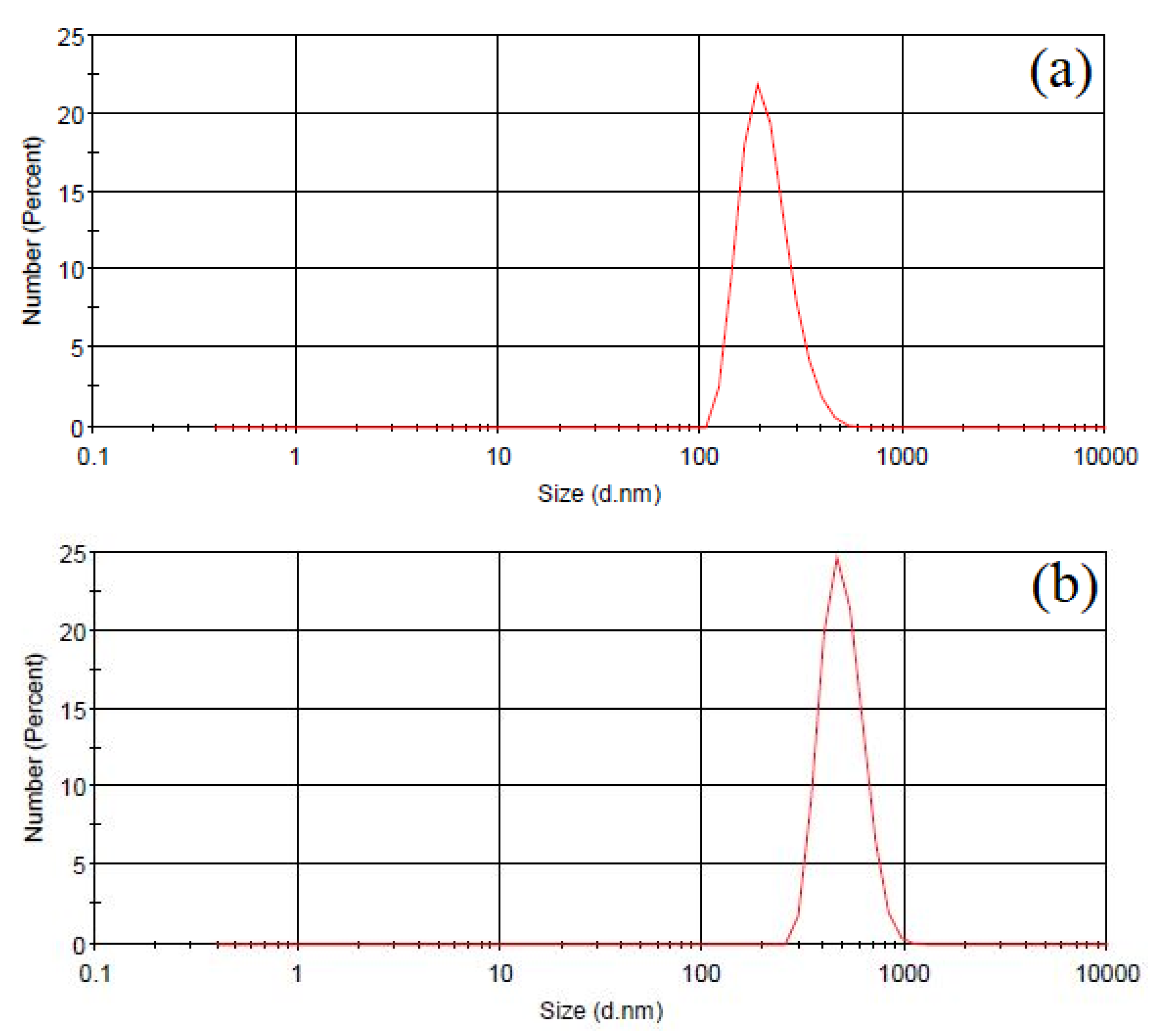
2. Materials and Methods

PEO coatings were formed on rectangular samples with a size of 30 × 10 × 10 mm made of the Zr-1Nb alloy. The samples were degreased with alcohol and then washed with distilled water. PEO treatment was carried out in the slurry electrolyte containing 9 g/L of sodium metasilicate pentahydrate Na2SiO3 5H2O, 5 g/L of sodium hypophosphite Na(PH2O2) and 6 g/L of submicron yttria powder Y2O3. The electrolyte was treated in a homogenizer for 3 min at an ultrasonic frequency of 40 kHz to stabilize the suspension. PEO treatment was carried out under the AC electrical mode (50 Hz) with an anode-to-cathode current ratio of 1:1 and sum current densities 20, 30, and 40 A/dm2. The duration of the PEO process was 60 min.
The yttria particle size in the electrolyte before and after PEO treatment was monitored by a dynamic light scattering analyzer (Malvern Zetasizer Nano, Malvern Panalytical, Malvern, UK) using NIBS technology (non-invasive backscattering). The working range of particle size determination is from 0.6 nm to 6 microns. The measurements were carried out at 20 °C. Figure 1a shows the particle size distribution of submicron yttria powder in the slurry electrolyte before PEO treatment. The average particle size in the electrolyte was 0.28 μm and corresponded to their initial average size, which indicates the absence of Y2O3 particles conglomerates in the slurry electrolyte before the start of the PEO treatment. Figure 1b shows the particle size distribution after PEO treatment for 60 min. The average particle size in the electrolyte increased and amounted to ~0.63 μm, which is associated with the coagulation of yttria particles during plasma electrolytic oxidation process.
The thickness of the PEO coatings was measured using an eddy current thickness gauge. 15 measurements were carried out for each sample. The roughness (parameter Ra) of the coatings was determined by TR 100 roughness meter (Time Group Inc., Beijing, China). The morphology and cross-sections structure were examined by SEM Quanta 600 (FEI Company, Eindhoven, the Netherlands) using the energy of accelerated electrons 20 keV. The imaging modes of secondary and backscattered electrons (Z contrast) were used. The elemental composition of the PEO coatings was studied using energy-dispersive (EDX) X-ray microanalysis TRIDENT XM 4 (FEI Company, Eindhoven, the Netherlands). The energy of accelerated electrons was 30 keV. The composition was determined at 20 points in each coating layer. Cross-section mapping was provided for coating formed at 40 A/dm2. An accelerating electron voltage was 20 keV. The map was collected for 40 min. The distribution of elements along the line at the boundary between alloy and PEO coating was obtained using an accelerating electron voltage of 15 keV. X-ray phase analysis of the coatings was carried out in copper β-filtered radiation λKα1,2 = 1.54178 Å on a vertical X-ray θ-θ diffractometer EMPYREAN (Malvern Panalytical, Malvern, UK). The phases were identified using the ICDDPDF-2 database.
The electrochemical behavior of bare samples and samples with PEO coatings was investigated in a 0.5% lithium hydroxide LiOH model corrosive solution. The studies were carried out in the three-electrode cell using PI-50-1 potentiostat with potentiodynamic polarization from the cathode to the anode field with a sweep rate of 1 mV/s. The Zr-1Nb alloy substrate and samples with coatings were used as working electrodes, the silver chloride electrode (Ag/AgCl) as reference electrode and a platinum plate as the auxiliary electrode. Potentiodynamic polarization measurements were carried out at room temperature and at heating the corrosive solution up to 100 °C. Polarization measurements were started after 5 min of immersion in the corrosive solution. After this time, the steady-state open circuit potential corresponding to the corrosion potential of the working electrode was obtained. The polarization experiments were conducted thrice for the various samples.

3. Results

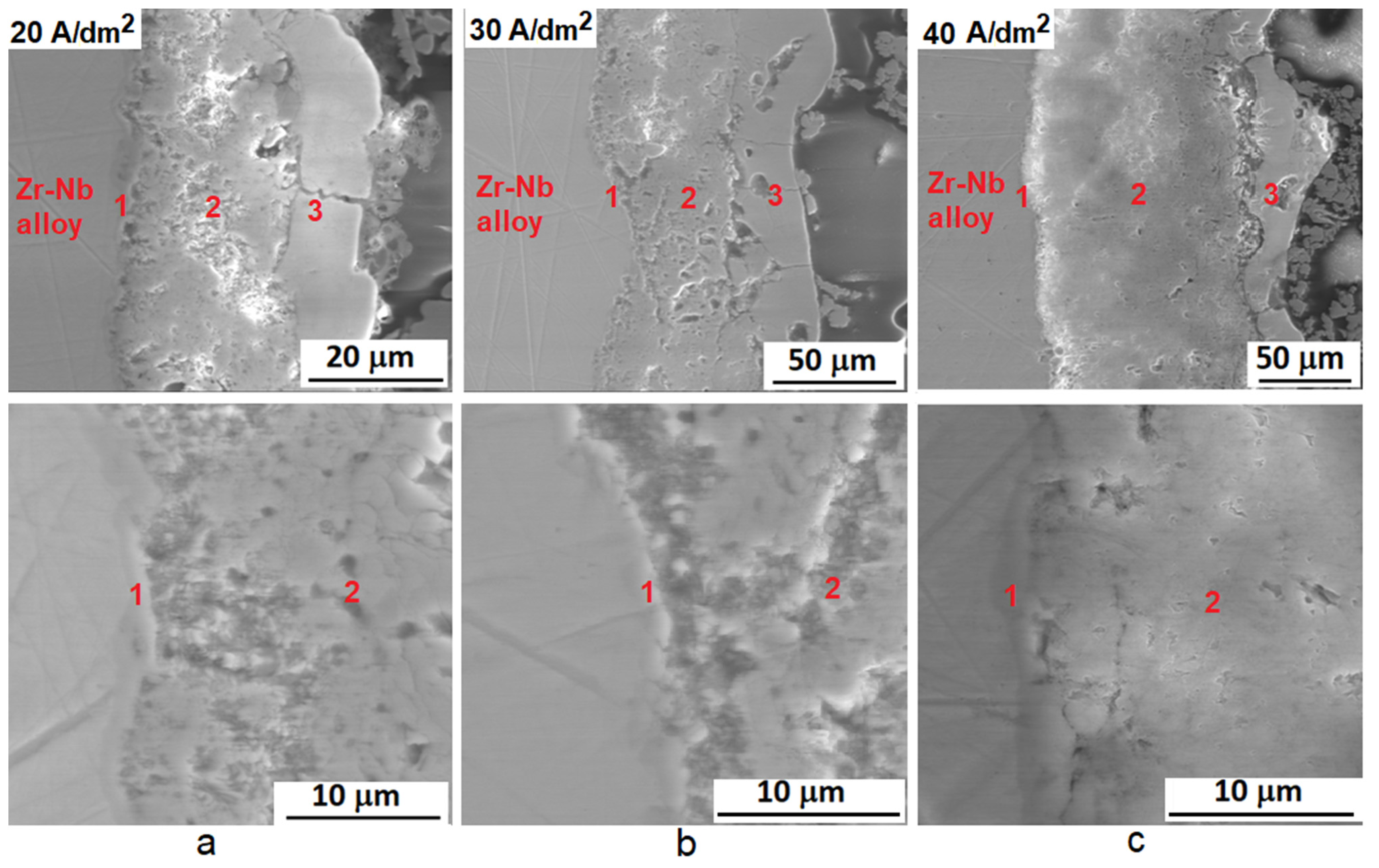
3.1. Thickness and Roughness of PEO Coatings

Table 1 shows the average values of thickness in the central part of samples and the roughness (parameter Ra) of coatings surface depending on the PEO current density. It can be seen that with increasing the current density, the thickness and the roughness of PEO coatings increase. Increasing coatings roughness is facilitated by functioning on the being-treated surface of larger and “long-lived” microdischarges that appear when the PEO process goes on for more than 20–30 min. This is also facilitated by increasing the PEO current density since the rate of coatings formation increases, their thickness rises, and large microdischarges appear at the earlier stage of the PEO process.

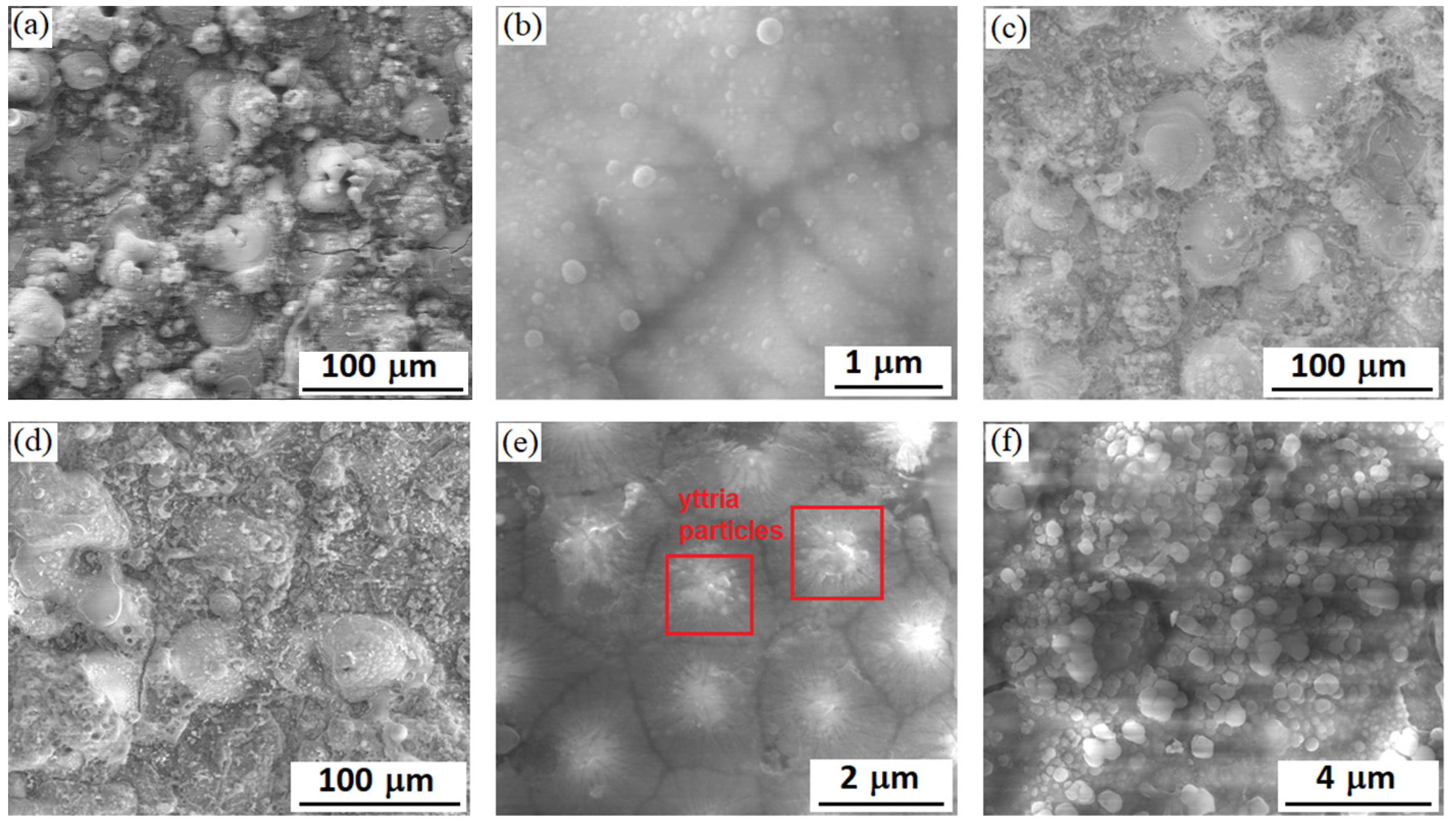
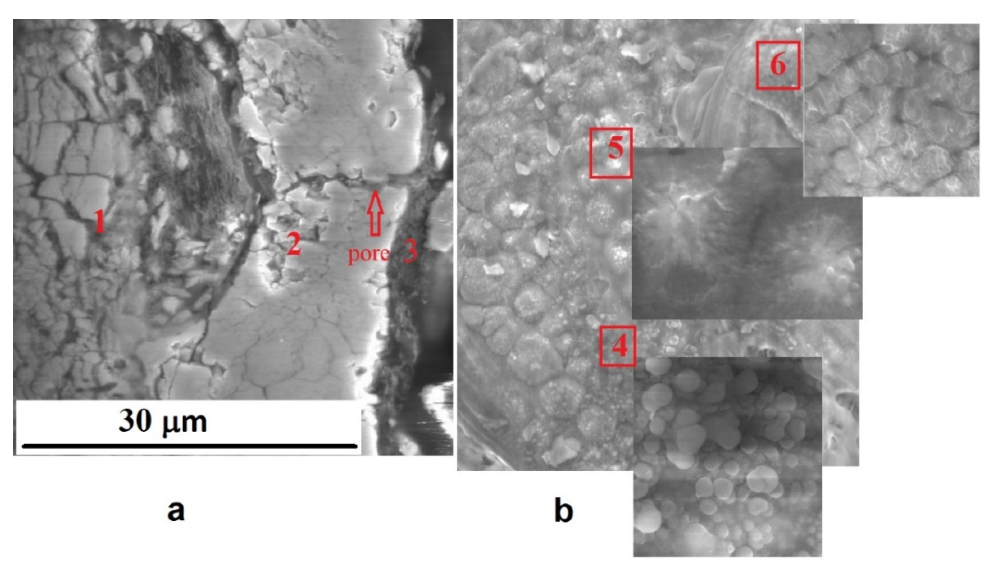
3.2. Surface Morphology

The surface morphology of coatings formed during 60 min of PEO is shown in Figure 2. Such structural features characterize PEO coatings on the Zr-1Nb alloy as protuberant craters areas and areas of globular structure between craters. The size of the craters increases with increasing PEO current density. At a PEO current density of 20 A/dm2, the crater’s size is ~30 μm (Figure 2a); at 30 A/dm2, it increases up to 50 μm (Figure 2c); and at 40 A/dm2, it reaches 100 μm for individual craters (Figure 2d). With increasing the PEO current density up to 40 A/dm2, the crater’s shape becomes less rounded, and often, the pore remains in the center. This is the trace after functioning of large microdischarge. With the increasing PEO current density, the crater packing density on the coating surface decreases, but the area of the fine globular structure zones, formed mainly from compounds with the participation of electrolyte components elements, increases [37]. In [37,40], the elemental analysis showed that such elements as Zr and O mainly characterize the craters areas, and elements of electrolyte components (for example Si) are characteristic for the intercrater areas.
On the surface of coatings, one can see adsorbed yttria particles up to 0.3 μm in size (Figure 2b,e,f), and their packing density increases with increasing PEO current density. So, for coatings formed at PEO current density 20 A/dm2, the packing density is ~4 × 10⁷ particles/m2, while the layer of particles on the surface of coatings is not continuous (Figure 2b). For PEO coatings formed at current density 40 A/dm2, the packing density of Y2O3 submicron particles increases several times, and in this case, their multilayer adsorption occurs (Figure 2f). Yttria particles cover the surface of PEO coating quite uniformly, which can promote to reduce its open porosity. In addition, when yttria particles enter the microdischarges area of operation, the temperature of which reaches several thousand degrees, they may be fused and form a solid solution with zirconia. In this case, the stabilization of high-temperature phases of zirconia can occur [35]. Figure 2e shows the central part of the crater area with fragments of melted Y2O3 particles for the coating formed at a PEO current density of 40 A/dm2. The electrophoretic interaction can also be responsible for the migration of submicron yttria particles to the being-treated surface at its anode polarization during PEO in the slurry electrolyte.

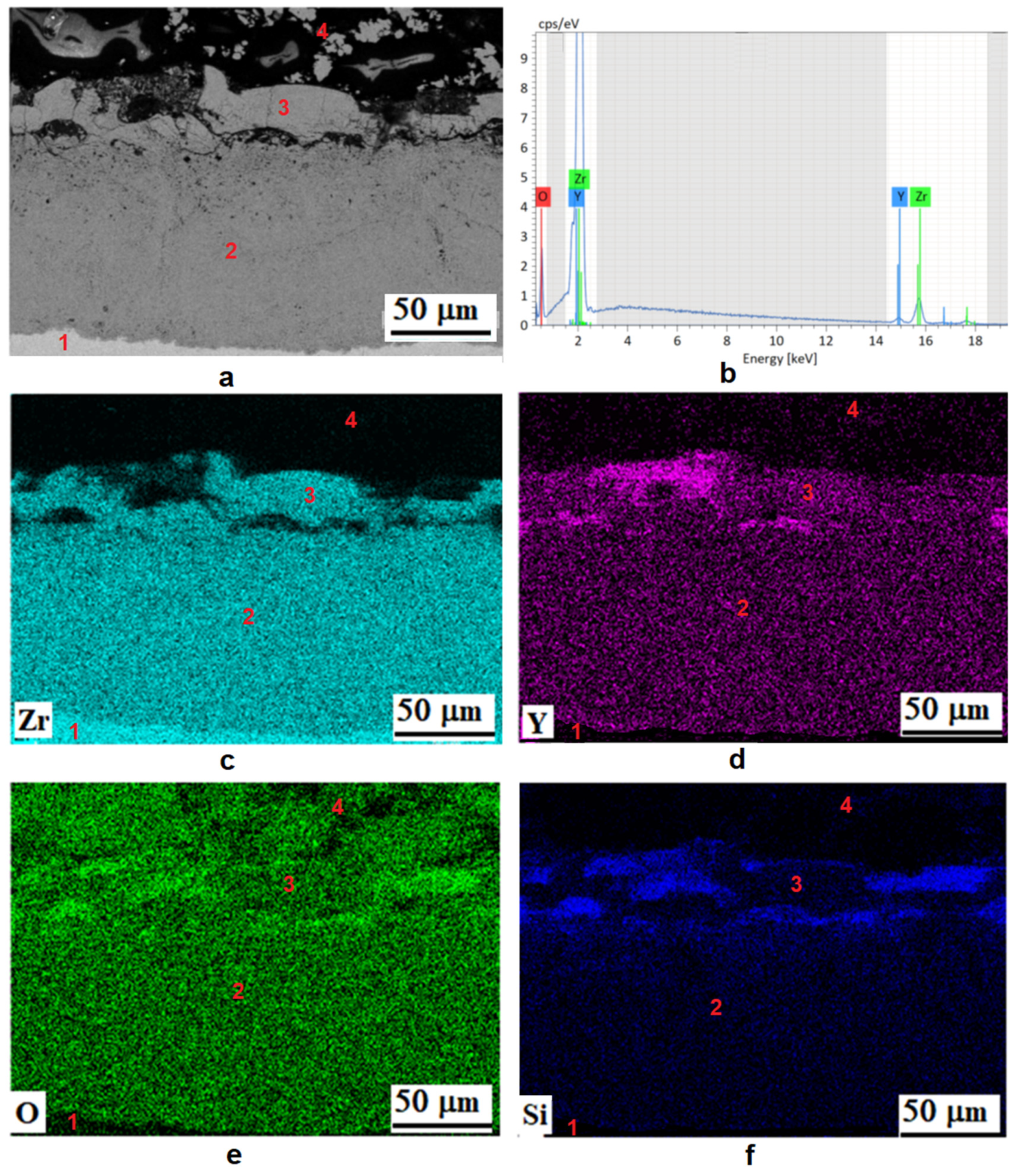
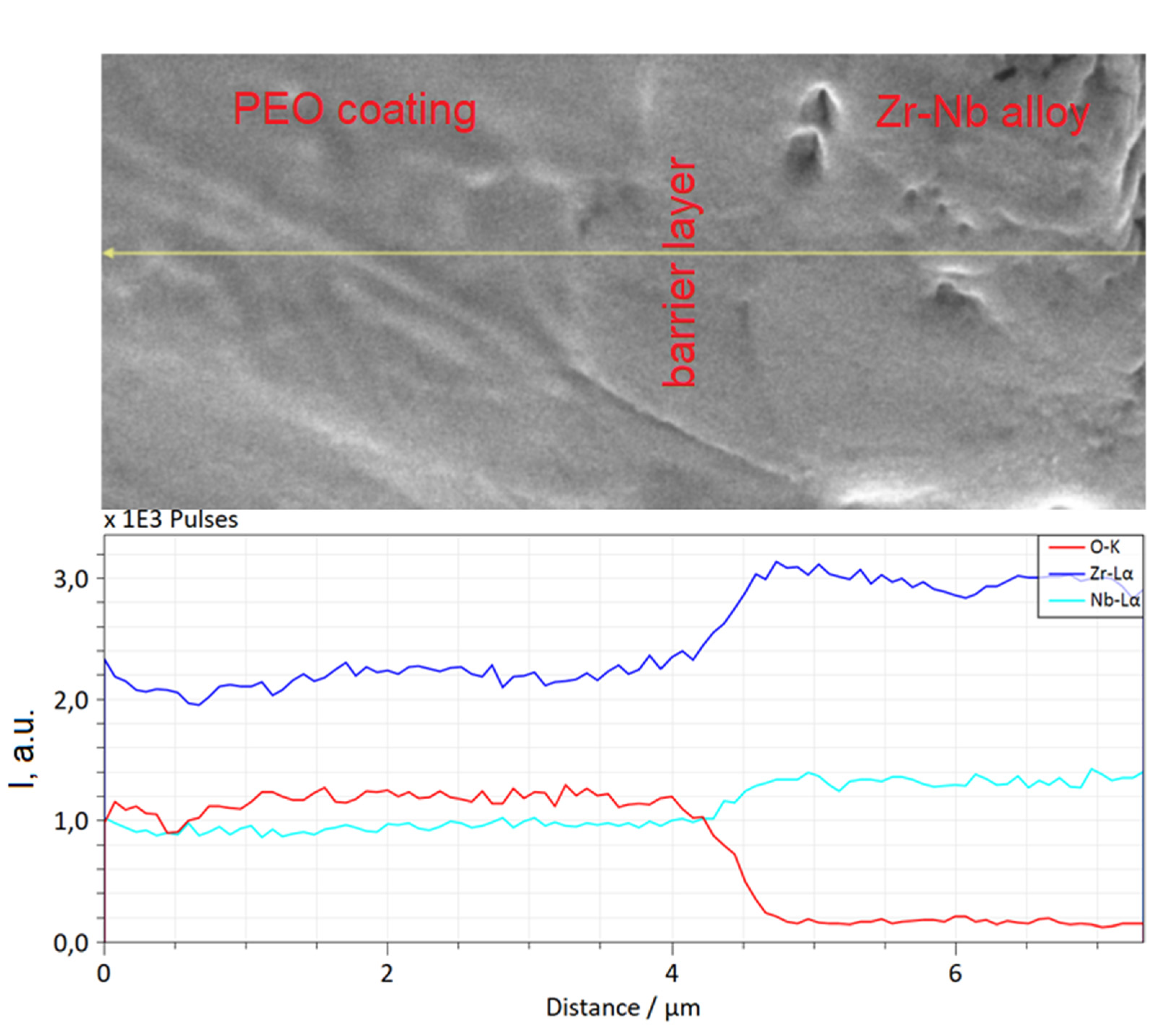
3.3. Cross-Sectional Microstructure and X-ray Microanalysis Data

With increasing the PEO current density from 20 to 40 A/dm2, the thickness of coatings enlarges from ~40 µm to ~150 µm (Figure 3). There are three main layers in the structure of PEO coatings: barrier, middle, and outer. The barrier layer at the boundary with the metal base has the highest density. Its thickness does not depend on the PEO current density and is ~1.5 μm (Figure 3). The middle layer consists of multi-directionally oriented crystallites 0.2–0.3 μm in size. The outer layer structure contains discharge channels that pierce it, elongated grains, and separate large pores. The thickness of the outer layer is ~10, ~20, and ~25 μm for coatings formed at PEO current densities 20, 30, and 40 A/dm2, respectively. The coatings formed at a PEO current density of 40 A/dm2 are characterized by the greatest inhomogeneity of the outer layer thickness. The thickness ratio of middle and outer layers is approximately 3:1 for PEO current densities 20 and 30 A/dm2 and approximately 5:1 for 40 A/dm2. The middle layer of the coating formed at the PEO current density 40 A/dm2 is characterized by the lowest porosity. The structure at the boundary with the barrier layer is also denser for coatings formed at a PEO current density 40 A/dm2 (Figure 3c) than at 20 and 30 A/dm2 (Figure 3a,b).
Figure 4 shows the map of the chemical elements’ distribution in the cross-section of the PEO coating formed at a current density 40 A/dm2. It can be seen that in the outer layer of the coating, the content of Si, Y, and O is noticeably higher than in the middle one, while the latter has a more uniform elemental composition. The outer layer is characterized by two types of areas: with an increased content of yttrium and other elements of electrolyte components (Si, Na, P) and dense areas containing Zr, Y, and Si. The elemental composition of the various coating layers according EDX data is shown in Table 2. The absence of Si and Y in the barrier layer can also be noted. An enlarged image of the barrier layer and the distribution of elements along the marked line are shown in Figure 5. It can be seen that the composition of the layer is characterized by a gradual decrease in zirconium and an increase in oxygen when passing from the alloy boundary to the middle layer of PEO coating.
Figure 6a shows cross-sectional microstructure, namely the middle layer 1, the outer layer 2, and the surface layer 3 of the PEO coating formed at current density 40 A/dm2. The surface layer is not continuous, and its thickness is several micrometers. Figure 6b shows that the surface layer repeats the relief of the underlying outer coating layer. In some areas, the layer is continuous (Figure 6b; area 4), and in some areas, only fragments of the layer remain in the form of islands containing melted particles (area 5) and in the form of a precipitate on the zirconia grains (area 6). Such structural features are possibly associated with the “later” effect of the microdischarges on this area. The presence of the surface layer (Figure 6a) can be explained by electrophoretic deposition of submicron Y2O3 particles from the slurry electrolyte that promotes filling the open-pore channels of the outer layer and raising the corrosion-protective ability of the PEO coating.

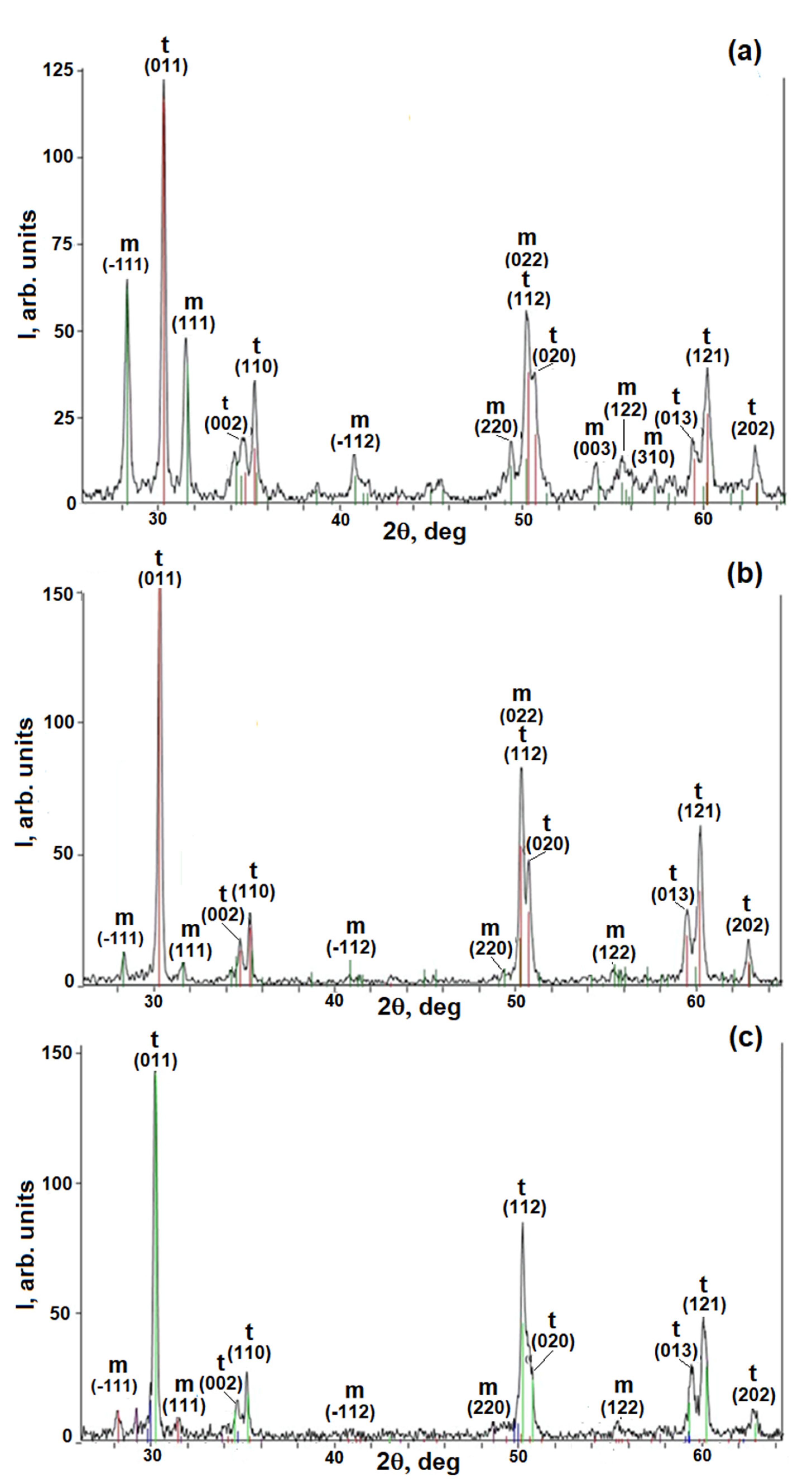
3.4. X-ray Phase Analysis

For quantitative phase analysis, we used the dependence of the diffraction peaks ratio I(101)t/I(111)m on the m-ZrO2 phase mass content in control powder samples with different mass contents of tetragonal t-ZrO2 and monoclinic m-ZrO2 phases of zirconia [35]. In the coating formed at a PEO current density of 20 A/dm2, the phases m-ZrO2 and t-ZrO2 were found in the amounts of ~34% and ~66%, respectively (Figure 7a). Increasing the PEO current density of up to 30 A/dm2 increased the t-ZrO2 phase content up to ~96% and decreased the m-ZrO2 phase content down to ~4% (Figure 7b). In the PEO coating formed at a current density of 40 A/dm2, the content of the t-ZrO2 phase decreased down to ~86%, and the m-ZrO2 phase increased up to ~14%. The peaks of the t-ZrO2 phase are broadened in the center, which suggests that the PEO coating also contains a high-temperature cubic c-ZrO2 phase of zirconia (Figure 7c). The c-ZrO2 phase could be formed due to high current density (40 A/dm2) and, consequently, higher temperatures in microdischarges operating during the PEO process. Increasing the current density leads to more intense incorporation of submicron Y2O3 particles into the structure of the forming PEO coating and stabilization of high-temperature tetragonal t-ZrO2 and cubic c-ZrO2 phases of zirconia, as was shown in [35,36,41] for yttria nanoparticles.

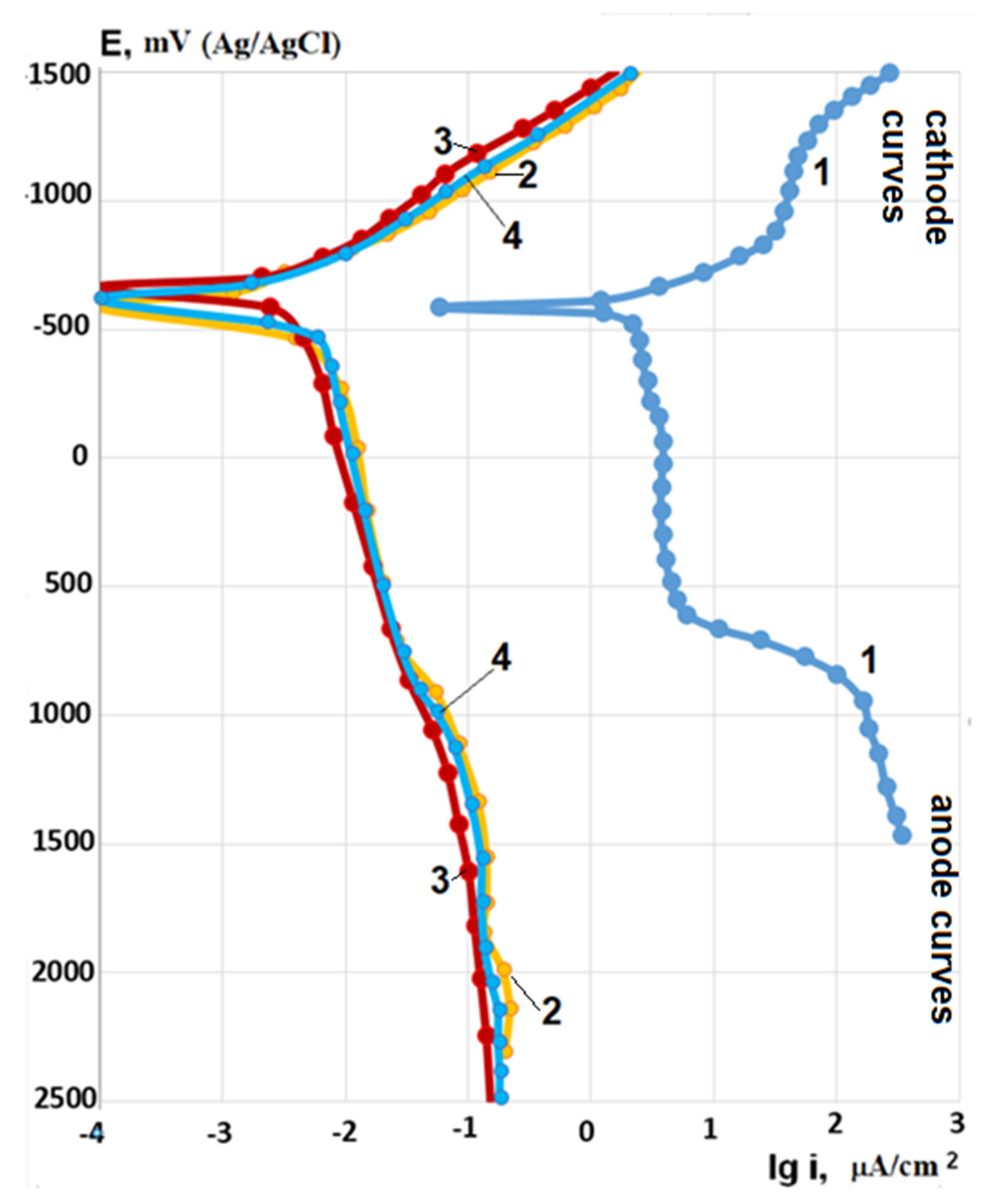
3.5. Electrochemical Polarization Studies

Potentiodynamic polarization measurements in 0.5% LiOH at room temperature show that for samples with PEO coatings, anode polarization currents at potential 0 mV are 1.5–2 orders of magnitude less than for the bare Zr-1Nb alloy, and with increasing potential more positive than +600 mV are less already by ~4 orders of magnitude (Figure 8). Cathode polarization currents of samples with PEO coatings are ~3 orders of magnitude lower than for the bare Zr-1Nb alloy. The anode and cathode polarization curves for PEO coatings formed at current densities 20 and 40 A/cm2 practically coincide. Very low anode current densities on potentiodynamic polarization curves for coatings indicate that the Zr-1Nb alloy on the bottom of through pores is in a deep passive state, and therefore, the PEO coatings reliably protect the base metal. Results of potentiodynamic polarization measurements are given in Table 3.
One of the most important parameters of PEO coatings, which determines their corrosion-protective ability, is through porosity. It can be estimated from the ratio of anodic polarization currents for samples with PEO coatings and bare Zr-1Nb alloy at a fixed anode potential. Based on the analysis of the polarization curves (Figure 8), it can be argued that the through porosity of PEO coatings does not exceed 1%. Since the rate of electrochemical corrosion is the superposition of cathode and anode reactions, it can be assumed from the analysis of polarization curves (Figure 8) that for samples with PEO coatings, it should be 1.5–2 orders of magnitude lower than for the bare Zr-1Nb alloy.
Heating the corrosive solution up to 100 °C, anode polarization currents increase by ~45 times for the bare Zr-1Nb alloy. For samples with coatings, polarization currents increase by 5–10 times depending on the PEO current density (Table 3), but they still correspond to the values of polarization current densities for the passive state (Figure 9).
As in tests at room temperature, the polarization curves for samples with PEO coatings formed at different current densities practically coincide (Figure 9). On bare Zr-1Nb alloy after anodic polarization in corrosive solution at 100 °C, the formation of corrosion products in the form of white flakes was observed, while no changes were observed for the samples with PEO coatings. Anodic polarization currents for bare Zr-1Nb alloy are about 2.5 orders of magnitude higher than for samples with PEO coatings.

4. Discussion

The main processes facilitating the incorporation of submicron Y2O3 particles during PEO are most likely the filling of the formed pores with electrolytes and the functioning of microdischarges [42]. In the discharge channels, the temperature reaches several thousand degrees, as a result of which melting of particles and the formation of a vapor phase can occur, leading to the formation of solid solutions and compounds with the base metal oxide. As a result of rapid cooling (up to ~107 K/s) upon extinction of the microdischarge, composite regions and, possibly, incorporated particles in an almost unchanged state are retained in the coating. The incorporation of particles during PEO can also occur as a result of the electrophoretic process [33,34]. In article [35], devoted to the formation of PEO coatings on the Zr-1Nb alloy in the slurry electrolyte with yttria nanopowder, an additional (apart from the barrier, middle and outer layers) surface layer with thickness ~5 μm was noted. It was enriched with elements of electrolyte components and contained conglomerates of Y2O3 nanoparticles. A similar layer was found in the present study. The presence of the surface layer (Figure 6a) can be explained by electrophoretic deposition of submicron Y2O3 particles from the slurry electrolyte that promotes filling of open-pore channels of the outer layer and rising of the corrosion-protective ability of PEO coating.
Earlier, it was shown in [37] that when the PEO process is carried out in a silicate-hypophosphite electrolyte without yttria additives, only the monoclinic modification m-ZrO2 of zirconia is present in the coating. High-temperature zirconia phases can be stabilized by adding oxides such as CaO, MgO, Y2O3, Al2O3, etc. They form a solid solution with zirconia, which prevents its phase transition to the low-temperature monoclinic phase m-ZrO2 during cooling. The phase transition (polymorphic transformation) of m-ZrO2 to t-ZrO2 occurs at 1170 °C and to c-ZrO2 at 2370 °C. High local temperatures in the areas near microdischarges during PEO allow the formation of high-temperature phases of zirconia. Due to the low thermal conductivity of zirconia, increasing PEO coatings thickness leads to deterioration in heat removal from the zones of microdischarges functioning, especially in the middle layer. The local temperature in the layer increase provides the formation of high-temperature t-ZrO2 and c-ZrO2 phases [36,41]. This is facilitated by yttria, which forms a solid solution with zirconia and stabilizes its high-temperature phases. Y2O3 submicron particles can be put into the zones of microdischarges action directly from the electrolyte and from the surface layer enriched with yttria. At the initial stages of the PEO process, the surface layer is practically absent, which reduces the input of Y2O3 into the coating, and therefore, the conditions for the formation of high-temperature zirconia phases are not entirely favorable. By increasing the current density and duration of the PEO process, the number of enriched yttria areas in the surface layer increases. As shown in [36], in the middle layer of the PEO coating near the metal substrate, as a result of better heat removal, the temperature for the polymorphic transformation of the low-temperature phase of zirconia into high-temperature phases is insufficient, which leads to increasing of m-ZrO2 phase content.
In accordance with the ZrO2–Y2O3 phase diagram, at yttria content of 6%, a tetragonal phase of zirconia t-ZrO2 is formed. More than 10% Y2O3 is required to stabilize the cubic phase c-ZrO2. SEM studies of PEO coatings surface have shown that at a high current density, the thicker surface layer of yttria particles is formed, which makes it quite possible to stabilize the cubic phase of zirconia on the local areas of coating.
The reason for the stabilization of high-temperature phases in PEO coating may also be the presence of silicon in the structure [30]. It is possible to form a solid solution ZrO2-Y2O3-SiO2 in the medium and outer layers of the coating. The content of Y and Si in the outer layer is rather high, which can lead to the formation of composite regions and medium-entropy oxides [43].
Different thickness of the coatings formed at changing of PEO current density does not play a significant role in the electrochemical behavior in the study in 0.5% LiOH, as evidenced by the close values of anodic and cathodic polarization currents. Apparently, only the quality of barrier layer had a significant effect since its thickness did not depend on the PEO current density and was practically unchanged. In many works, the high corrosion-protective ability of thinner PEO coatings was noted. However, thicker and more wear-resistant top layers can protect the barrier layer, which is responsible for the corrosion-protective ability of PEO coatings, from mechanical stress and prevent its destruction.

5. Conclusions

PEO coatings with thicknesses of 40 to 150 μm were formed on the zirconium alloy Zr-1Nb (1% Nb) in the slurry electrolyte containing 9 g/L sodium metasilicate pentahydrate and 5 g/L of sodium hypophosphite with the addition of 6 g/L of submicron yttria powder. The PEO treatment was carried out under AC electrical mode (50 Hz) with anode-to-cathode current ratio 1:1 and sum current densities 20, 30, and 40 A/dm2. The duration of the PEO process was 60 min.
At a PEO current density of 20 A/dm2, the coating contains monoclinic and tetragonal phases of zirconia with a predominance of tetragonal one. By increasing the PEO current density up to 30 A/dm2, the content of the tetragonal phase of zirconia increase to ~96%. In the coating formed at a PEO current density of 40 A/dm2, the content of the monoclinic phase increases, and the tetragonal phase decreases, but the peaks of the tetragonal phase broaden in the center suggests the appearance of the cubic ZrO2 phase. Increasing PEO current density also promotes the formation of coating surface layers containing submicron particles of yttria.
PEO coatings showed high corrosion-protective ability in 0.5% LiOH solution. Anode polarization currents at potential 0 mV up to 2 orders of magnitude less than for the bare Zr-1Nb alloy. A somewhat higher corrosion resistance of the coating formed at a PEO current density of 30 A/dm2 is most likely associated with its phase composition. The dependence of polarization currents on PEO current density during the tests in 0.5% LiOH turned out to be insignificant. When heating the corrosive solution up to 100 °C, the anode polarization currents for samples with coatings increase by 5–10 times depending on the PEO current density, but they still correspond to the values of polarization current densities for the passive state.

Author Contributions

Conceptualization, S.S. and I.S.; methodology, S.S. and M.G.; software M.G.; validation, A.A. and I.S.; formal analysis, A.A.; investigation, S.S. and M.G.; resources, I.S.; data curation, I.S.; writing—original draft preparation, S.S.; writing—review and editing, A.A. and S.S.; visualization, S.S. and M.G.; supervision, I.S.; project administration, S.S.; funding acquisition, I.S. All authors have read and agreed to the published version of the manuscript.

Funding

This research was funded by the Russian Science Foundation, project number 21-79-30058.

Acknowledgments

The work is carried out on the equipment of the Center of collective use of MSUT “STANKIN”.

Conflicts of Interest

The authors declare no conflict of interest.

References

  1. Yakushkin, A.A.; Vysikaylo, P.I. Modification of the surface and coating application on fuel cladding tubes for nuclear reactors. Bull. Mosc. Reg. St. Univ. Ser. Phys. Math. 2018, 4, 92–111. [Google Scholar]
  2. Tang, C.; Stueber, M.; Seifert, H.J.; Steinbrueck, M. Protective coatings on zirconium-based alloys as accident-tolerant fuel (ATF) claddings. Corros. Rev. 2017, 35, 141–165. [Google Scholar] [CrossRef]
  3. Sagiroun, M.I.A.; Xinrong, C. Zirconium-Based Cladding Coating Technique for Oxidation, Corrosion and Embrittlement Reduction at High-Temperature: An Overview. IOP Conf. Ser. Mater. Sci. Eng. 2019, 649, 012008. [Google Scholar] [CrossRef] [Green Version]
  4. Vega-Morón, R.C.; Castro, G.R.; Melo-Máximo, D.V.; Méndez-Ménde, J.V.; Melo-Máximo, L.; Oseguera-Peña, J.E.; Meneses-Amador, A. Adhesion and mechanical properties of Ti films deposited by DC magnetron sputtering. Surf. Coat. Technol. 2018, 349, 1137–1147. [Google Scholar] [CrossRef]
  5. Bischoff, J.; Delafoy, C.; Vauglin, C.; Barberis, P.; Roubeyrie, C.; Perche, D.; Duthoo, D.; Schuster, F.; Brachet, J.-C.; Schweitzer, E.W.; et al. AREVA NP’s enhanced accident-tolerant fuel developments: Focus on Cr-coated M5 cladding. Nucl. Eng. Technol. 2018, 50, 223–228. [Google Scholar] [CrossRef]
  6. Zhong, W.; Mouche, P.A.; Han, X.; Heuser, B.J.; Mandapaka, K.K.; Was, G.S. Performance of iron-chromium-aluminum alloy surface coatings on Zircaloy 2 under high temperature steam and normal BWR operating conditions. J. Nucl. Mater. 2016, 470, 327–338. [Google Scholar] [CrossRef] [Green Version]
  7. Kashkarov, E.B.; Sidelev, D.V.; Rombaeva, M.R.; Kudiiarov, V.N.; Lomygin, A. Formation of Cr-Zr gradient layer by magnetron sputtering and ion mixing. MATEC Web Conf. 2019, 298, 00088. [Google Scholar] [CrossRef]
  8. Ševeček, M.; Gurgen, A.; Seshadri, A.; Che, Y.; Wagih, M.; Phillips, B.; Champagne, V.; Shirvan, K. Development of Cr cold spray—Coated fuel cladding with enhanced accident tolerance. Nucl. Eng. Technol. 2018, 50, 229–236. [Google Scholar] [CrossRef]
  9. Kuprin, A.S.; Belous, V.A.; Voyevodin, V.N.; Bryk, V.V.; Vasilenko, R.L.; Ovcharenko, V.D.; Reshetnyak, E.N.; Tolmachova, G.N.; V’yugov, P.N. Vacuum-arc chromium-based coatings for protection of zirconium alloys from the high-temperature oxidation in air. J. Nucl. Mater. 2015, 465, 400–406. [Google Scholar] [CrossRef]
  10. Kashkarov, E.B.; Nikitenkov, N.N.; Syrtanov, M.S.; Tyurin, Y.I.; Le, Z. Formation of titanium interlayer by vacuum arc deposition to increase the durability of titanium nitride coatings under thermal cycling conditions. J. Surf. Investig. 2015, 9, 1277–1280. [Google Scholar] [CrossRef]
  11. Khatkhatay, F.; Jiao, L.; Jian, J.; Zhang, W.; Jiao, Z.; Gan, J.; Zhang, H.; Zhang, X.; Wang, H. Superior corrosion resistance properties of TiN-based coatings on Zircaloy tubes in supercritical water. J. Nucl. Mater. 2014, 451, 346–351. [Google Scholar] [CrossRef]
  12. Kashkarov, E.B.; Nikitenkov, N.N.; Sutygina, A.N.; Bezmaternykh, A.O.; Kudiiarov, V.N.; Syrtanov, M.S.; Pryamushko, T.S. Hydrogenation behavior of Ti-implanted Zr-1Nb alloy with TiN films deposited using filtered vacuum arc and magnetron sputtering. Appl. Surf. Sci. 2018, 432, 207–213. [Google Scholar] [CrossRef]
  13. Alat, E.; Motta, A.T.; Comstock, R.J.; Partezana, J.M.; Wolfe, D.E. Multilayer (TiN, TiAlN) ceramic coatings for nuclear fuel cladding. J. Nucl. Mater. 2016, 478, 236–244. [Google Scholar] [CrossRef] [Green Version]
  14. Stueber, M.; Holleck, H.; Leiste, H.; Seemann, K.; Ulrich, S.; Ziebert, C. Concepts for the design of advanced nanoscale PVD multilayer protective thin films. J. Alloys Compd. 2009, 483, 321–333. [Google Scholar] [CrossRef]
  15. Daub, K.; Persaud, S.Y.; Rebak, R.B.; Nieuwenhove, V.; Ramamurthy, S.; Nordin, H. Investigating Potential Accident Tolerant Fuel Cladding Materials and Coatings. In Proceedings of the 18th International Conference on Environmental Degradation of Materials in Nuclear Power Systems—Water Reactors, Marriott, Portland, 13–17 August 2017; Volume 2, pp. 215–234. [Google Scholar]
  16. Younker, I.; Fratoni, M. Neutronic evaluation of coating and cladding materials for accident tolerant fuels. Prog. Nucl. Energy 2016, 88, 10–18. [Google Scholar] [CrossRef] [Green Version]
  17. Apelfeld, A.V.; Belkin, P.N.; Borisov, A.M.; Vasin, V.A.; Krit, B.L.; Ludin, V.B.; Somov, O.V.; Sorokin, V.A.; Suminov, I.V.; Frantskevich, V.P. Modern Technologies for Modification of Materials Surface and Formation of Protective Coatings. In Microarc Oxidation; Renome: Moscow-St.-Petersburg, Russia, 2017; Volume 1, pp. 345–438, (In Russian). ISBN 978-5-91918-832-2. [Google Scholar]
  18. Nie, X.; Meletis, E.I.; Jiang, J.C.; Leyland, A.; Yerokhin, A.L.; Matthews, A. Abrasive wear/corrosion properties and TEM analysis of Al2O3 coatings fabricated using plasma electrolysis. Surf. Coat. Technol. 2002, 149, 245–251. [Google Scholar] [CrossRef]
  19. Curran, J.A.; Clyne, T.W. Thermo-Physical Properties of Plasma Electrolytic Oxide Coatings on Aluminum. Surface and Coatings Technology. Surf. Coat. Technol. 2005, 199, 168–176. [Google Scholar] [CrossRef]
  20. Dehnavi, V.; Shoesmith, D.W.; Luan, B.L.; Yari, M.; Liu, X.Y.; Rohani, S. Corrosion properties of plasma electrolytic oxidation coatings on an aluminium alloy–The effect of the PEO process stage. Mater. Chem. Phys. 2015, 161, 49–58. [Google Scholar] [CrossRef]
  21. Liu, C.; Liu, P.; Huang, Z.; Yan, Q.; Guo, R.; Li, D.; Jiang, G.; Shen, D. The correlation between the coating structure and the corrosion behavior of the plasma electrolytic oxidation coating on aluminum. Surf. Coat. Technol. 2016, 286, 223–230. [Google Scholar] [CrossRef]
  22. Treviño, M.; Garza-Montes-de-Oca, N.F.; Pérez, A.; Juárez, A.; Colás, R.; Hernández-Rodríguez, M.A.L. Wear of an aluminium alloy coated by plasma electrolytic oxidation. Surf. Coat. Technol. 2012, 206, 2213–2219. [Google Scholar] [CrossRef]
  23. Su, J.F.; Nie, X.; Hu, H.; Tjong, J. Friction and counterface wear influenced by surface profiles of plasma electrolytic oxidation coatings on an aluminum A356 alloy. J. Vac. Sci. Technol. A 2012, 30, 061402. [Google Scholar]
  24. Chen, Y.; Nie, X.; Northwood, D.O. Investigation of Plasma Electrolytic Oxidation (PEO) coatings on a Zr-2.5Nb alloy using high temperature/pressure autoclave and tribological tests. Surf. Coat. Technol. 2010, 205, 1774–1782. [Google Scholar] [CrossRef]
  25. Cheng, Y.; Wu, F.; Dong, J.; Wu, X.; Xue, Z.; Matykina, E.; Skeldon, P.; Thompson, G.E. Comparison of plasma electrolytic oxidation of zirconium alloy in silicate- and aluminate-based electrolytes and wear properties of the resulting coatings. Electrochim. Acta 2012, 85, 25–32. [Google Scholar] [CrossRef]
  26. Zou, Z.; Xue, W.; Jia, X.; Du, J.; Wang, R.; Weng, L. Effect of Voltage on Properties of Microarc Oxidation Films Prepared in Phosphate Electrolyte on Zr–1Nb Alloy. Surf. Coat. Technol. 2013, 222, 62–67. [Google Scholar] [CrossRef]
  27. Cheng, Y.; Matykina, E.; Arrabal, R.; Skeldon, P.; Thompson, G.E. Plasma electrolytic oxidation and corrosion protection of Zircaloy-4. Surf. Coat. Technol. 2012, 206, 3230–3239. [Google Scholar] [CrossRef]
  28. Malayoğlu, U.; Tekin, K.C.; Malayoğlu, U.; Belevi, M. Mechanical and electrochemical properties of PEO coatings on zirconium alloy. Surf. Eng. 2020, 36, 800–808. [Google Scholar] [CrossRef]
  29. Cheng, Y.; Wu, F. Plasma electrolytic oxidation of zircaloy-4 alloy with DC regime and properties of coatings. Trans. Nonferrous Met. Soc. China 2012, 22, 1638–1646. [Google Scholar] [CrossRef]
  30. Farrakhov, R.G.; Parfenov, E.V.; Mukaeva, V.R.; Gorbatkov, M.V.; Tarasov, P.V.; Fatkullin, A.R.; Rameshbabu, N.; Ravisankar, B. Effect of Electrolyte Composition on Protective Properties of the PEO Coating on Zr-1Nb Zirconium. Alloy. Surf. Eng. Appl. Electrochem. 2019, 55, 514–521. [Google Scholar] [CrossRef]
  31. Parfenov, E.V.; Mukaeva, V.R.; Farrakhov, R.G.; Saikiran, A.; Hariprasad, S.; Manoj, P.; Lokesh, E.; Rameshbabu, N. Effect of frequency on plasma electrolytic oxidation of zirconium in pulsed unipolar mode. IOP Conf. Ser. Mater. Sci. Eng. 2019, 672, 012010. [Google Scholar] [CrossRef] [Green Version]
  32. Wang, Y.; Tang, H.; Han, X.; Feng, W.; Zhou, X.; Peng, S.; Zhang, H. Oxidation resistance improvement of Zr-4 alloy in 1000 °C steam environment using ZrO2/FeCrAl bilayer coating. Surf. Coat. Technol. 2018, 349, 807–815. [Google Scholar] [CrossRef]
  33. Arun, S.; Arunnellaiappan, T.; Rameshbabu, N. Fabrication of the nanoparticle incorporated PEO coating on commercially pure zirconium and its corrosion resistance. Surf. Coat. Technol. 2016, 305, 264–273. [Google Scholar] [CrossRef]
  34. Arun, S.; Hariprasad, S.; Saikiran, A.; Ravisankar, B.; Parfenov, E.V.; Mukaeva, V.R.; Rameshbabu, N. The effect of graphite particle size on the corrosion and wear behaviour of the PEO-EPD coating fabricated on commercially pure zirconium. Surf. Coat. Technol. 2019, 363, 301–313. [Google Scholar]
  35. Apelfeld, A.V.; Ashmarin, A.A.; Borisov, A.M.; Vinogradov, A.V.; Savushkina, S.V.; Shmytkova, E.A. Formation of zirconia tetragonal phase by plasma electrolytic oxidation of zirconium alloy in electrolyte comprising additives of yttria nanopowder. Surf. Coat. Technol. 2017, 328, 513–517. [Google Scholar] [CrossRef]
  36. Savushkina, S.V.; Ashmarin, A.A.; Apelfeld, A.V.; Borisov, A.M.; Vinogradov, A.V.; Polyansky, M.N.; Bogdashkina, N.L. Investigation of zirconia tetragonal phase coatings formed by plasma electrolytic oxidation. IOP Conf. Ser. J. Phys. Conf. Ser. 2017, 857, 012037. [Google Scholar] [CrossRef] [Green Version]
  37. Apelfeld, A.V.; Borisov, A.M.; Krit, B.L.; Ludin, V.B.; Polyansky, M.N.; Romanovsky, E.A.; Savushkina, S.V.; Suminov, I.V.; Tkachenko, N.V.; Vinogradov, A.V.; et al. The study of plasma electrolytic oxidation coatings on Zr and Zr-1% Nb alloy at thermal cycling. Surf. Coat. Technol. 2015, 269, 279–285. [Google Scholar] [CrossRef]
  38. Savushkina, S.V.; Polyansky, M.N.; Borisov, A.M.; Vinogradov, A.V.; Lyudin, V.B.; Dankova, T.E.; Agureev, L.E. Investigation of the Heat Resistance of Zirconia Coatings Generated by Microarc Oxidation. J. Surf. Investig. X-Ray Synchrotron Neutron Tech. 2016, 10, 406–411. [Google Scholar] [CrossRef]
  39. Cheng, Y.; Wu, F.; Matykina, E.; Skeldon, P.; Thompson, G.E. The influences of microdischarge types and silicate on the morphologies and phase compositions of plasma electrolytic oxidation coatings on Zircaloy-2. Corros. Sci. 2012, 59, 307–315. [Google Scholar] [CrossRef]
  40. Borisov, A.M.; Savushkina, S.V.; Vinogradov, A.V.; Tkachenko, N.V.; Vostrikov, V.G.; Romanovsky, E.A.; Polyansky, M.N.; Ashmarin, A.A. Investigation of zirconia coatings obtained under plasma action in electrolytes. J. Surf. Investig. X-Ray Synchrotron Neutron Tech. 2014, 8, 366–370. [Google Scholar] [CrossRef]
  41. Apelfeld, A.V.; Betsofen, S.Y.; Borisov, A.M.; Vladimirov, B.V.; Savushkina, S.V.; Knyazev, E.V. Stabilization of the high-temperature phases in ceramic coatings on zirconium alloy produced by plasma electrolytic oxidation. IOP Conf. Ser. J. Phys. Conf. Ser. 2016, 748, 012019. [Google Scholar] [CrossRef] [Green Version]
  42. O’Hara, M.; Troughton, S.C.; Francis, R.; Clyne, T.W. The incorporation of particles suspended in the electrolyte into plasma electrolytic oxidation coatings on Ti and Al substrates. Surf. Coat. Technol. 2020, 385, 125354. [Google Scholar] [CrossRef]
  43. Sarkar, A.; Wang, Q.; Schiele, A.; Chellali, M.R.; Wang, D.; Brezesinski, T.; Hahn, H.; Velasco, L.; Breitung, B. High-Entropy Oxides: Fundamental Aspects and Electrochemical Properties. Adv. Mater. 2019, 31, 1806236. [Google Scholar] [CrossRef] [PubMed]
Figure 1. Particle size distribution of submicron Y2O3 powder in the slurry electrolyte before (a) and after (b) PEO treatment for 60 min.
Metals 11 01392 g001
Figure 2. SEM images in the mode of backscattered electrons of surface morphology: PEO coatings formed at current densities 20 (a), 30 (c), and 40 (d) A/dm2; submicron yttria particles on the surface of coatings formed at current densities 20 (b) and 40 A/dm2 (e,f).
Metals 11 01392 g002
Figure 3. SEM images in the mode of backscattered electrons of the cross-sectional microstructure: PEO coatings formed at current densities 20 (a), 30 (b), and 40 (c) A/dm2 and their microstructures at the boundary of barrier and middle layers. 1—barrier layer, 2—middle layer, 3—outer layer.
Metals 11 01392 g003
Figure 4. The chemical elements distribution map in the cross-section of the PEO coating formed at a current density of 40 A/dm2. (a) SEM image in backscattered electrons of the cross-sectional microstructure; (b) typical EDX spectra of the middle layer area, the distribution of elements Zr (c), Y (d), O (e), and Si (f). 1—Zr-1Nb alloy, 2—middle layer of PEO coating, 3—outer layer, 4—polished sample compound.
Metals 11 01392 g004
Figure 5. The cross-sectional microstructure of the barrier layer and elements distribution along the marked line.
Metals 11 01392 g005
Figure 6. The cross-sectional microstructure (a) and surface morphology (b) of the PEO coating formed at a current density 40 A/dm2. 1—middle layer; 2—outer layer; 3—surface layer; 4—layer of Y2O3 particles; 5—residual melted areas of the surface layer with fragments of yttria particles; 6—grains of zirconia and melted areas of the surface layer.
Metals 11 01392 g006
Figure 7. X-ray diffraction patterns of PEO coatings formed at current densities 20 (a), 30 (b), and 40 (c) A/dm2. m—monoclinic phase of ZrO2; t—tetragonal phase of ZrO2.
Metals 11 01392 g007
Figure 8. Potentiodynamic polarization curves after 5 min of immersion in corrosive solution 0.5% LiOH at room temperature for bare Zr-1Nb alloy (1) and samples with coatings formed at a PEO current density of 20 (2), 30 (3), and 40 (4) A/dm2.
Metals 11 01392 g008
Figure 9. Potentiodynamic polarization curves after 5 min of immersion in corrosive solution 0.5% LiOH at 100 °C for the bare Zr-1Nb alloy (1) and samples with coatings formed at PEO current densities 20 (2), 30 (3), and 40 (4) A/dm2.
Metals 11 01392 g009
Table 1. The thickness and roughness of PEO coatings.
PEO Current Density, A/dm2Roughness Ra, μmThickness, μm
200.540
300.5113
400.8150
Table 2. EDX Data.
Table 2. EDX Data.
LayerElement, at%
ZrOYSiNaP
Outer layerYttria-poor areas296821--
Yttria-rich areas563111911
Medium layer277111--
Barrier layer3763----
Table 3. Results of potentiodynamic polarization measurements; i—anode current density at potential 0 mV (Ag/AgCl).
SampleCorrosive Mediumi, μA/cm2
at 0 V (Ag/AgCl)
lgi, [μA/cm2]
Bare Zr-1Nb alloy0.5% LiOH, room temperature0.087096−1.06
PEO, 20 A/dm20.5% LiOH, room temperature0.002188−2.66
PEO, 30 A/dm20.5% LiOH, room temperature0.001413−2.85
PEO, 40 A/dm20.5% LiOH, room temperature0.002188−2.66
Bare Zr-1Nb alloy0.5% LiOH, heated up to 100 °C3.8018940.58
PEO, 20 A/dm20.5% LiOH, heated up to 100 °C0.01122−1.95
PEO, 30 A/dm20.5% LiOH, heated up to 100 °C0.011749−1.93
PEO, 40 A/dm20.5% LiOH, heated up to 100 °C0.01122−1.95
Publisher’s Note: MDPI stays neutral with regard to jurisdictional claims in published maps and institutional affiliations.

