
Development of an Aluminum-Based Hybrid Billet Material for the Process-Integrated Foaming of Hollow Co-Extrusions


Abstract
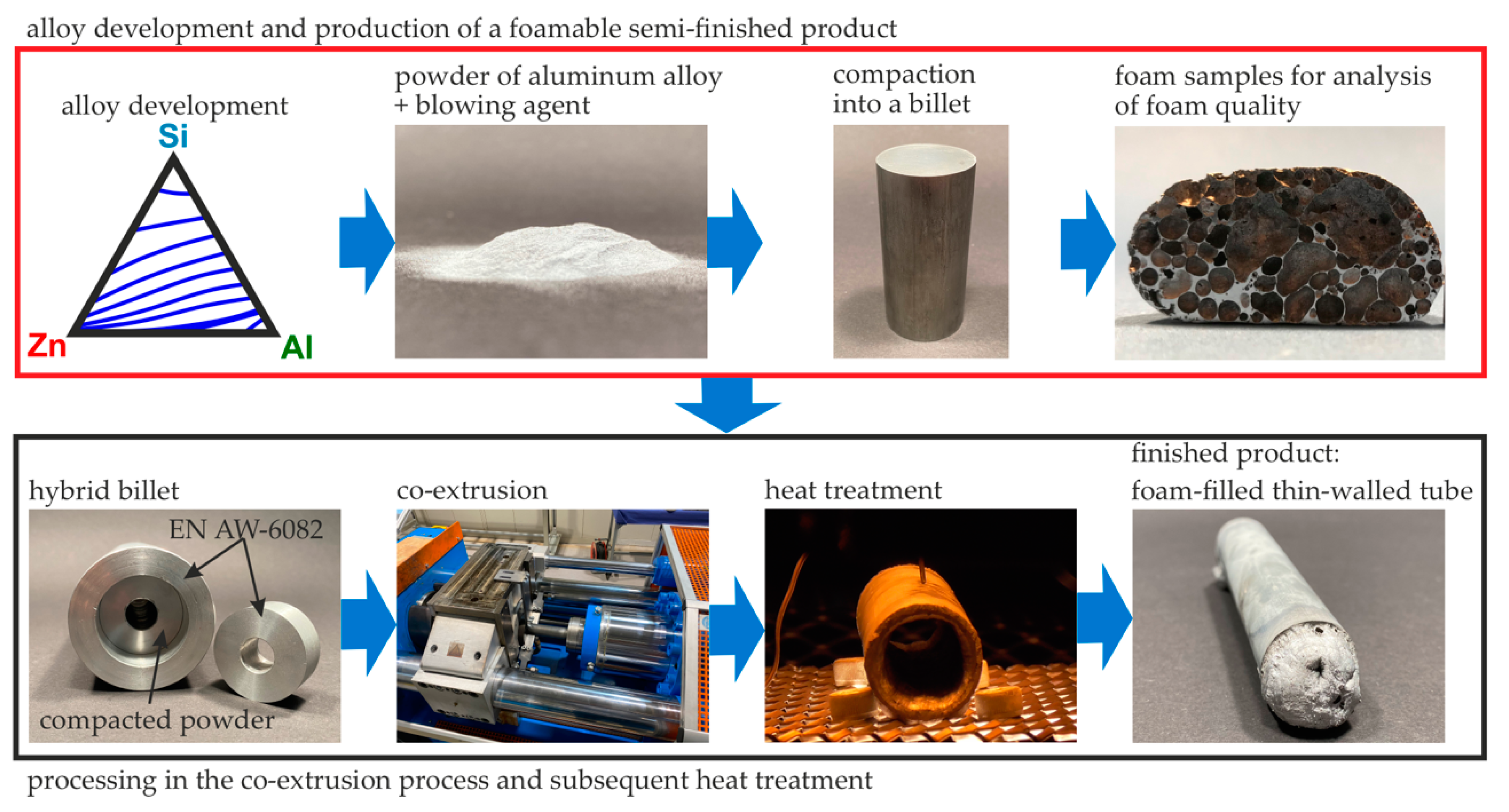
:1. Introduction
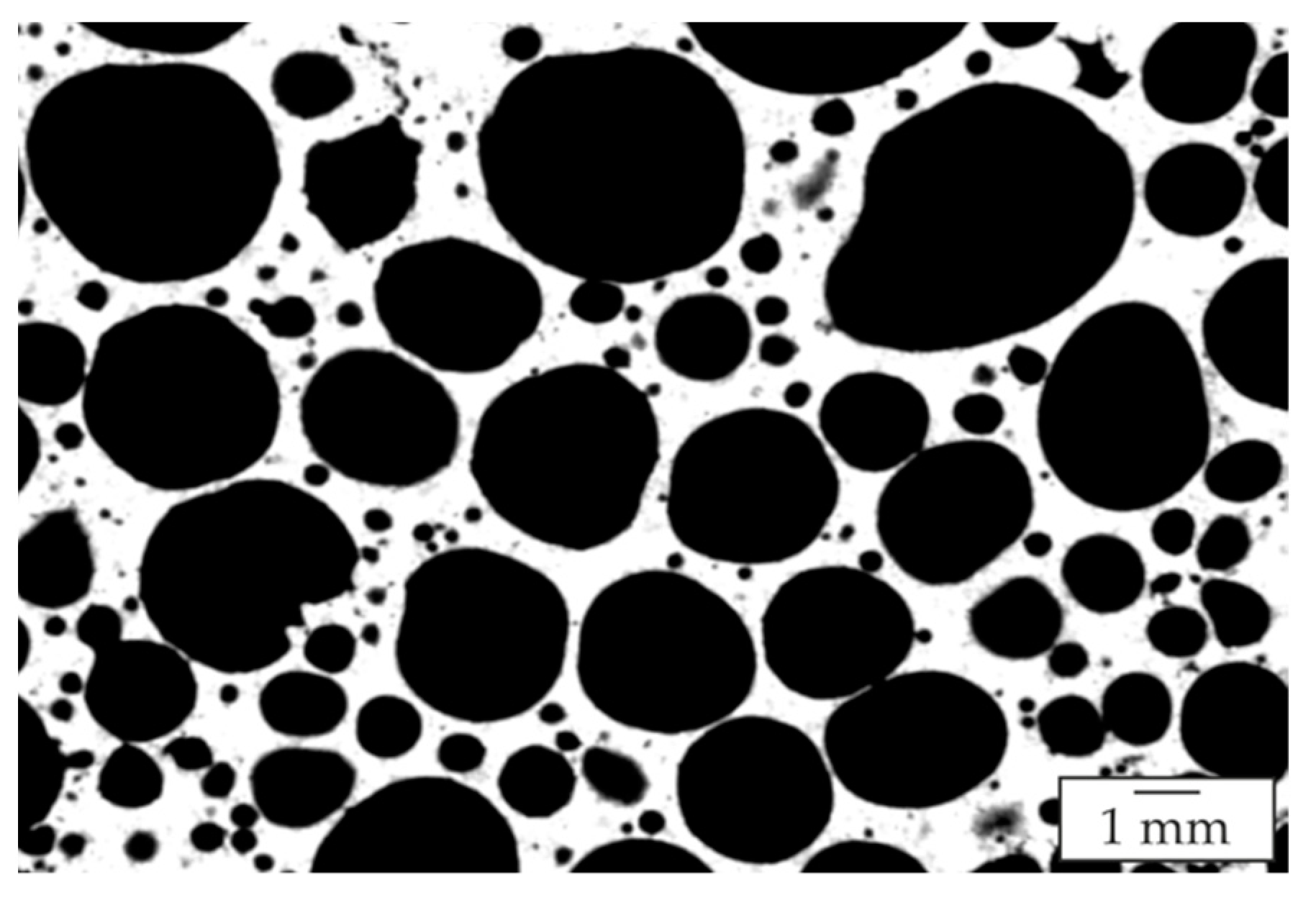
- inner porosity of each APM foam element;
- outer porosity of an assembly of many APM foam elements, which varies with different APM foam element sizes [14].
2. Materials and Methods
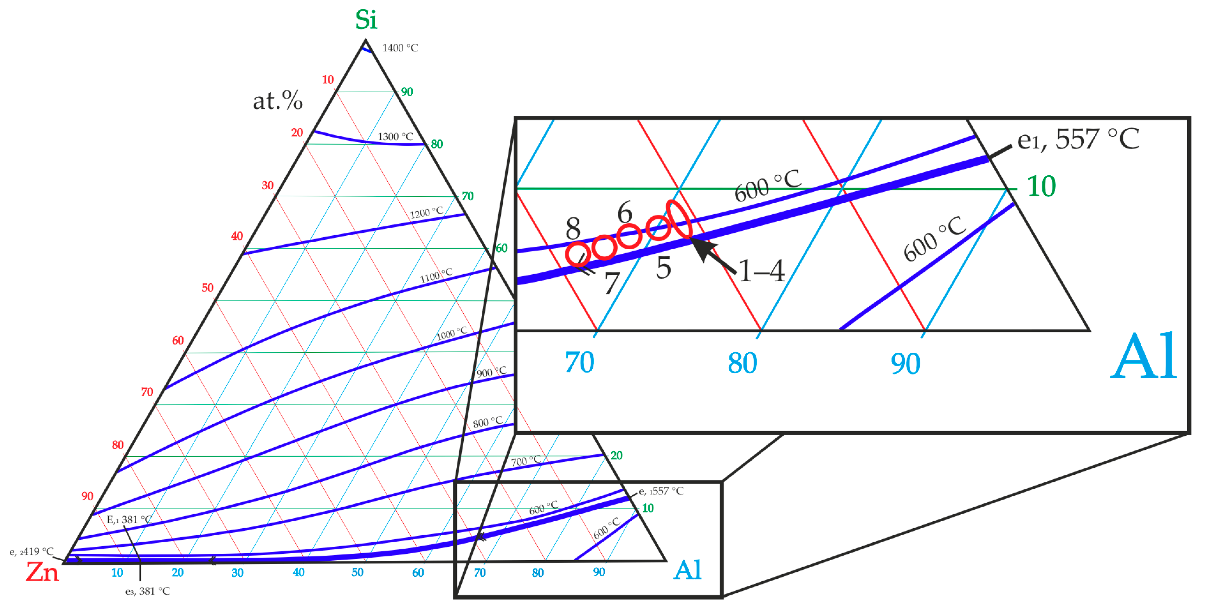
2.1. Determination of the Appropriate Melting Temperature Interval
2.2. Alloy Development
2.3. Casting Process of the Selected Alloys
2.4. Casting of the Target Alloy and Powder Atomization
2.5. Charaterization of the Alloys
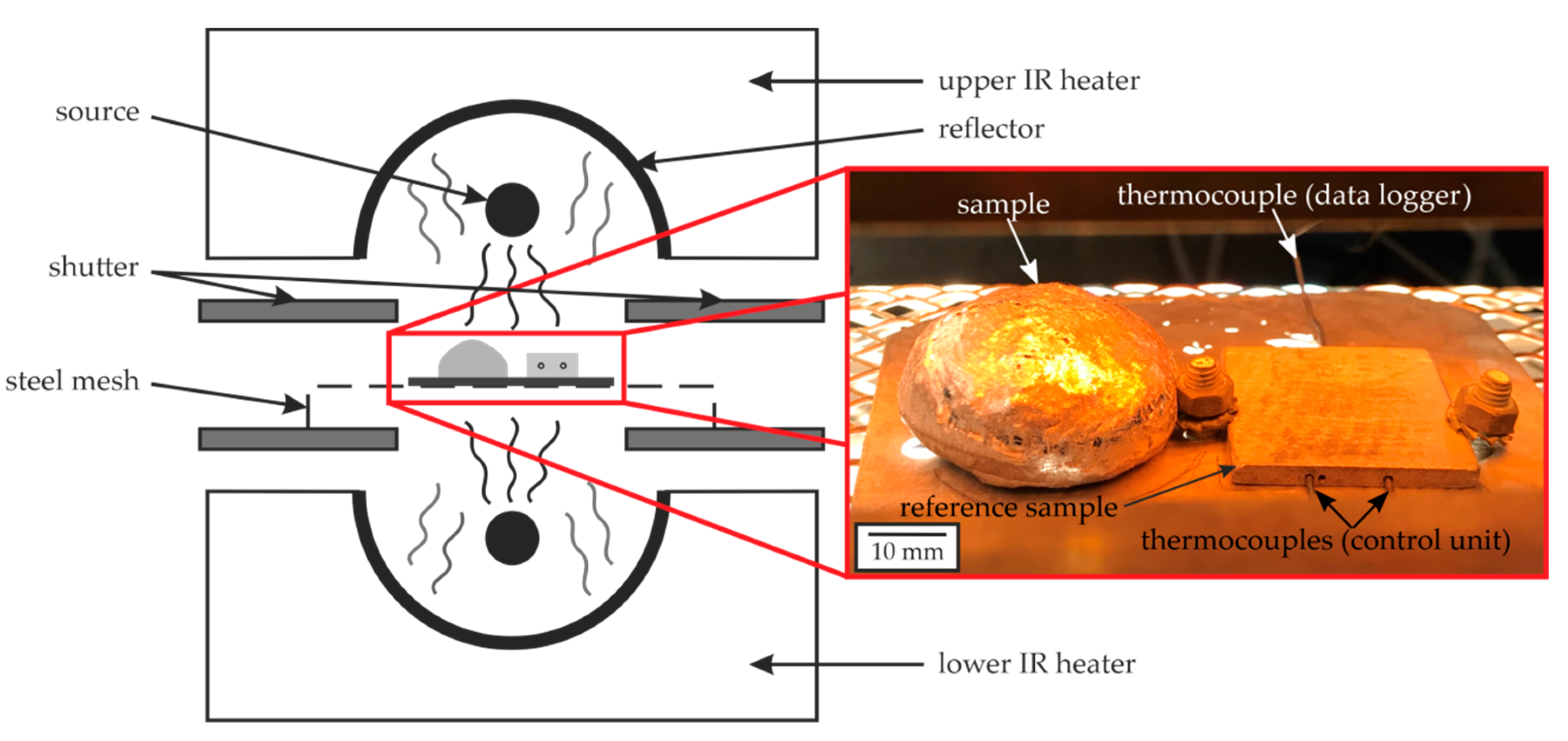
2.6. Design of Experiments for the Characterization of the Foaming Behavior
- homogeneity of the pore distribution relative to their position inside the sample;
- distribution of the occurring pore sizes and wall thicknesses;
- overall volume percentage of the porosity of the foam.
2.7. XRM Measurements of the Foamed Samples
3. Results
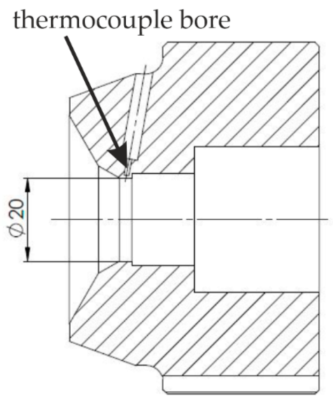
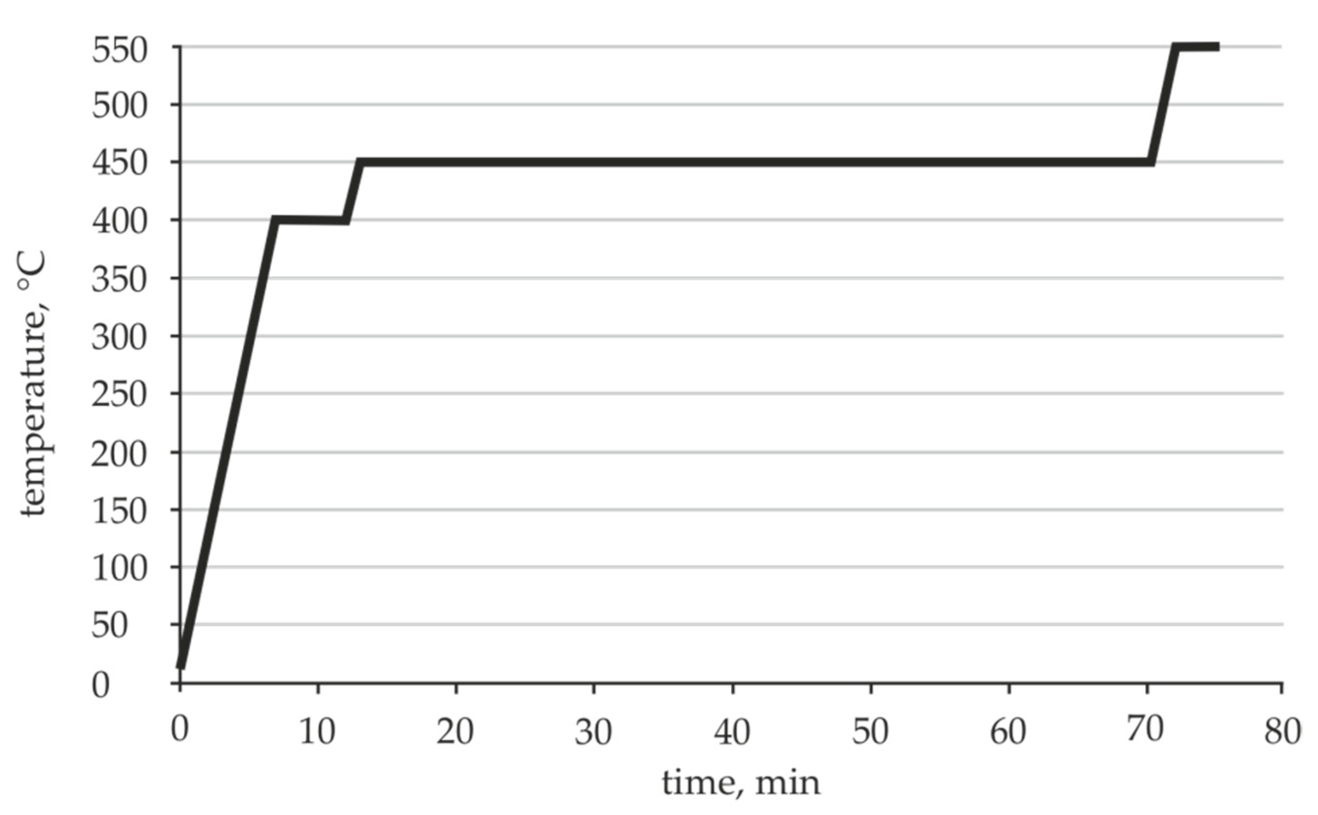
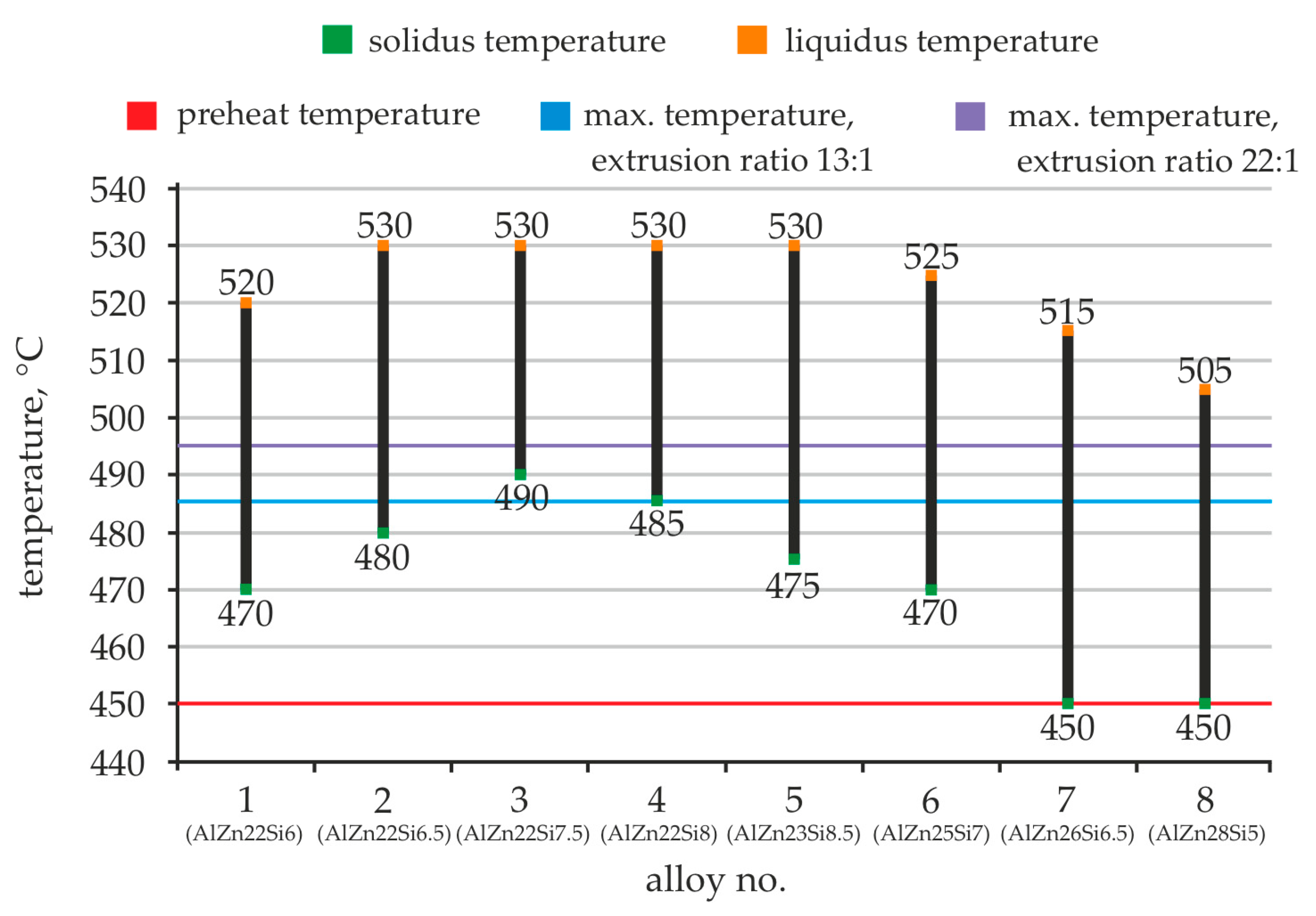
3.1. Die Temperatures in the Extrusion Processes and Melting Interval of the Novel Al-Zn-Si Alloys
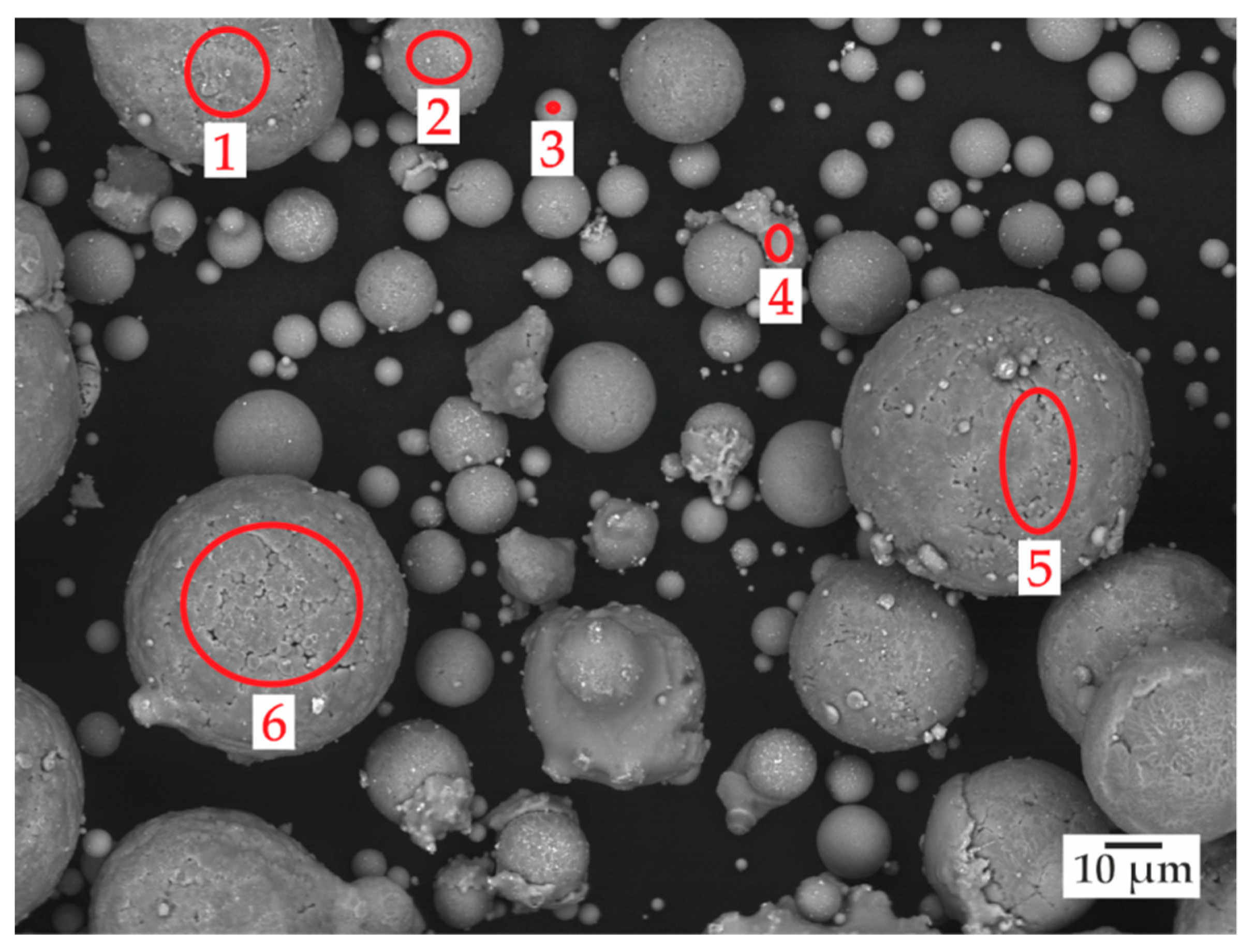
3.2. Characterization of the Powder Particles Produced via EIGA
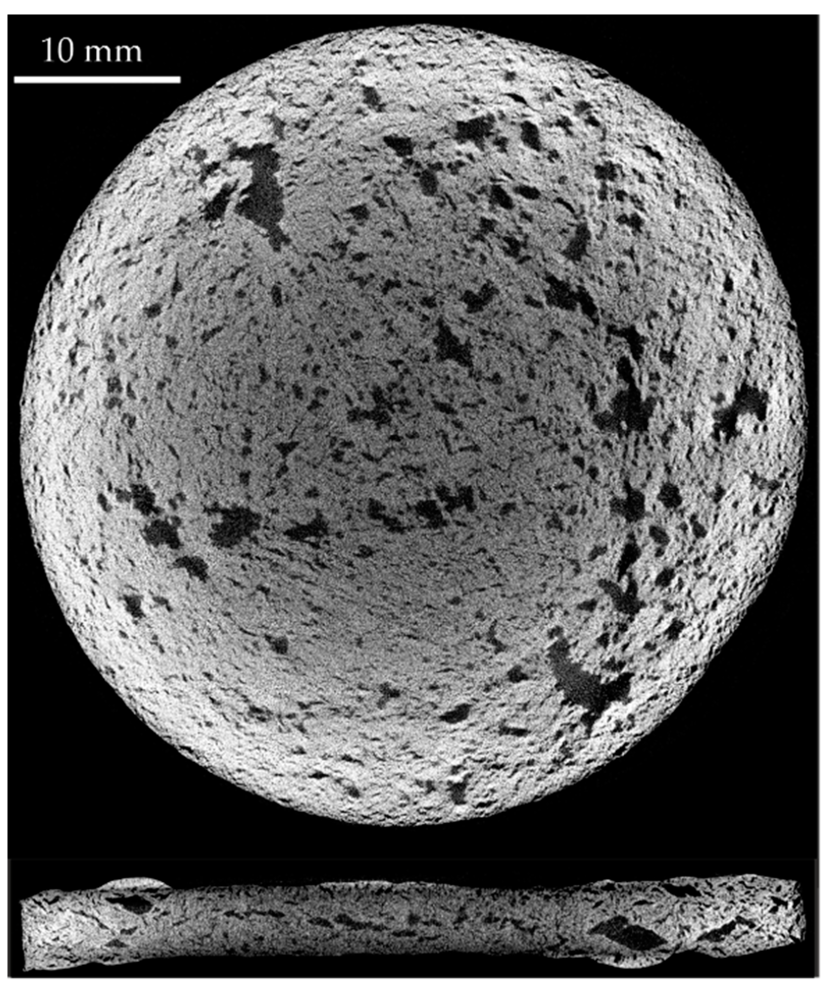
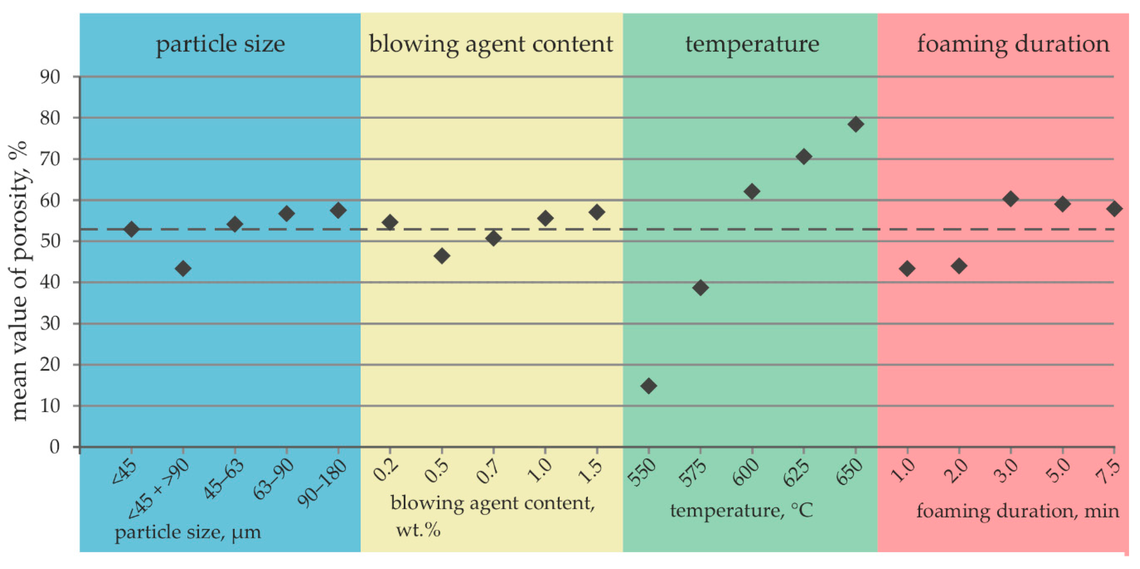
3.3. Porosity of the Foamed Alloy
- Category I: Porosity < 49%
- Category II: Porosity from 49% to 69%
- Category III: Porosity > 69%
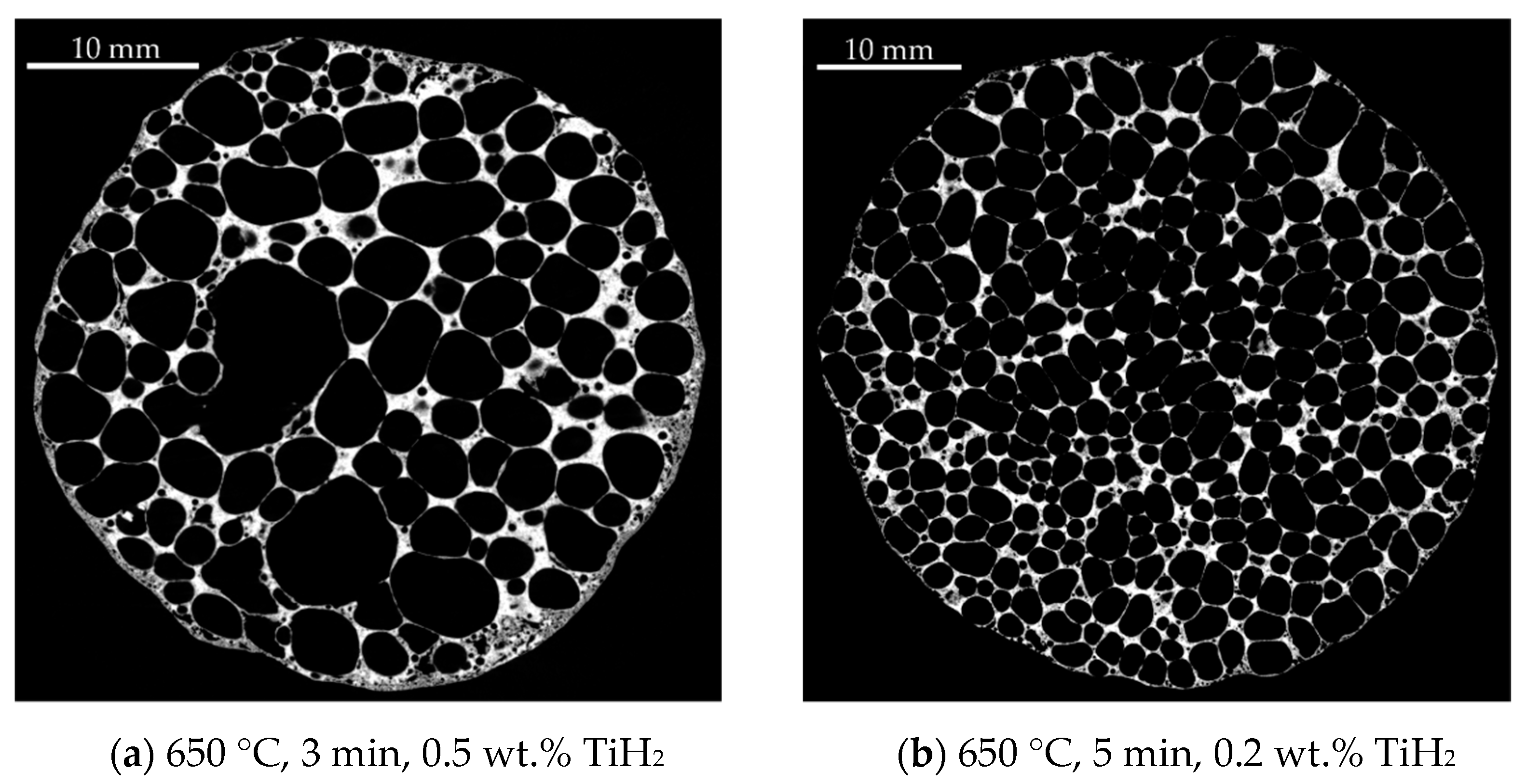
3.4. Foam Quality
- Homogeneity level 1: The foam has an overall non-uniform foam structure
- Homogeneity level 2: The foam has a more homogeneous cell structure overall, but contains significantly enlarged pores in some areas and a large number of very small pores in other areas
- Homogeneity level 3: The foam has an almost equal pore size and distribution over the entire sample.
4. Discussion
5. Conclusions and Outlook
- With the composition AlZn22Si6, a promising alloy with a melting range of 470–520 °C was developed for a process-integrated foaming during co-extrusion.
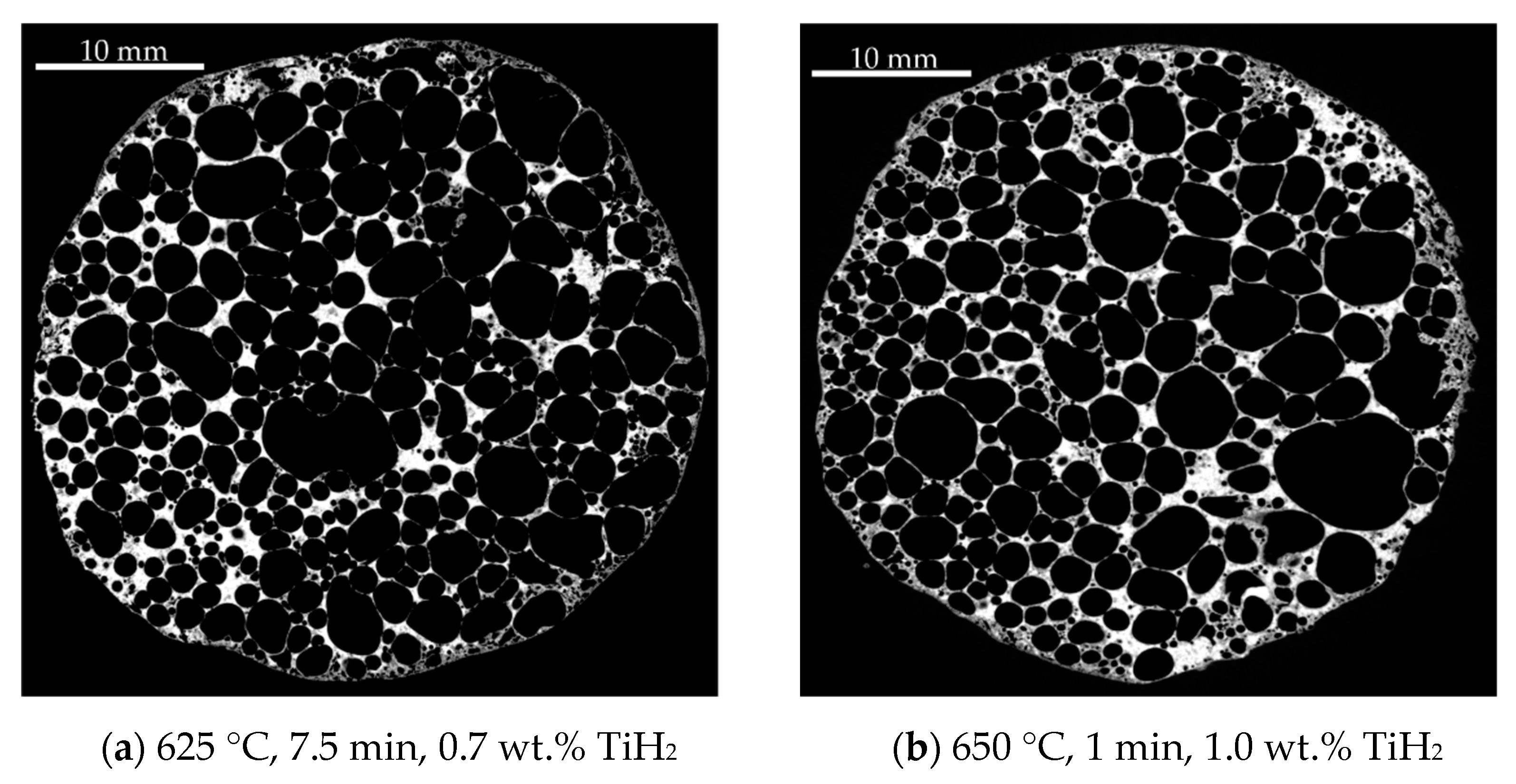
- In standalone foaming experiments, it was observed that the temperature selected for foaming has the greatest influence on the porosity of the metal foam made of the developed AlZnSi alloy. The further parameters, time, particle size and blowing agent content, are less critical with respect to the evolution of the porosity.
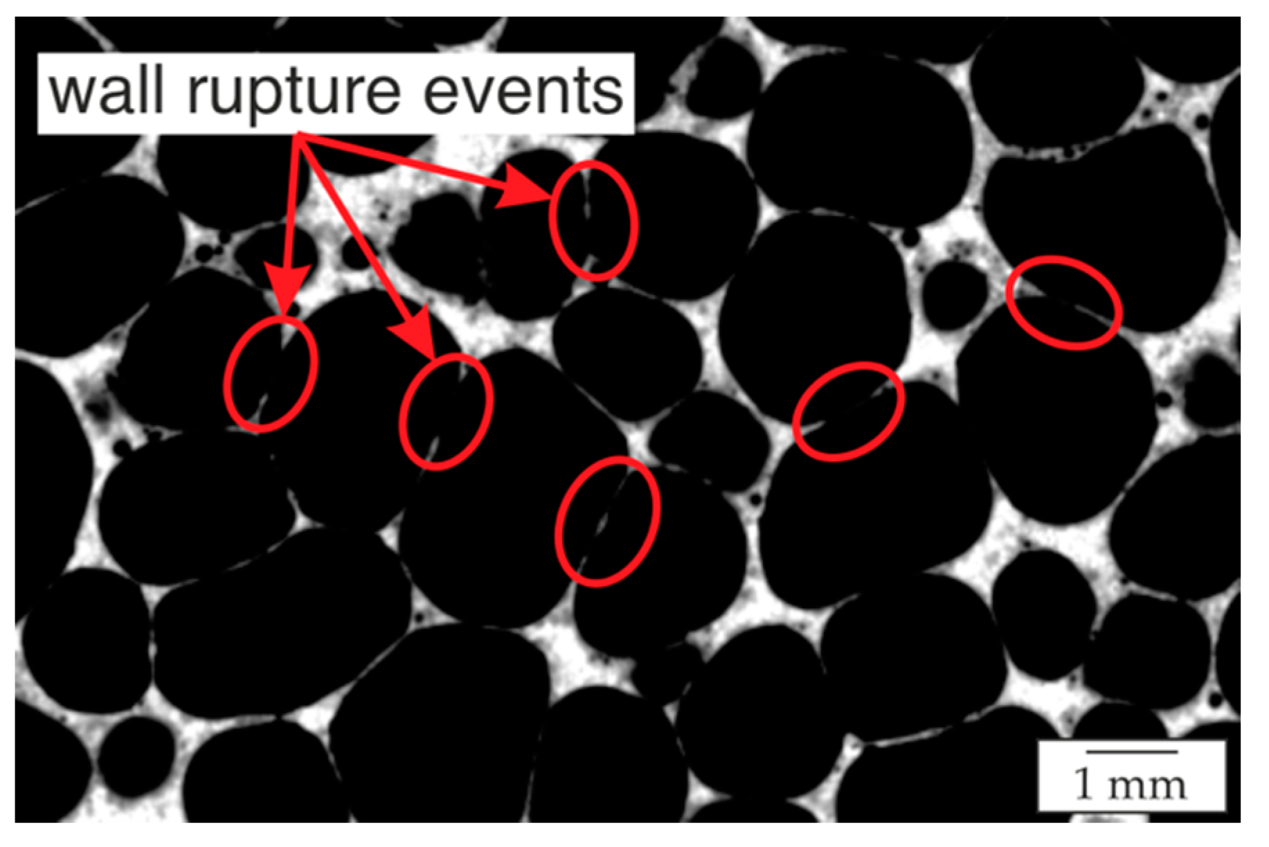
- The homogeneity of the pore structure was significantly influenced by the blowing agent content. The foaming temperature parameter had hardly any influence on the homogeneity of the pore distribution over the sample and volume size.
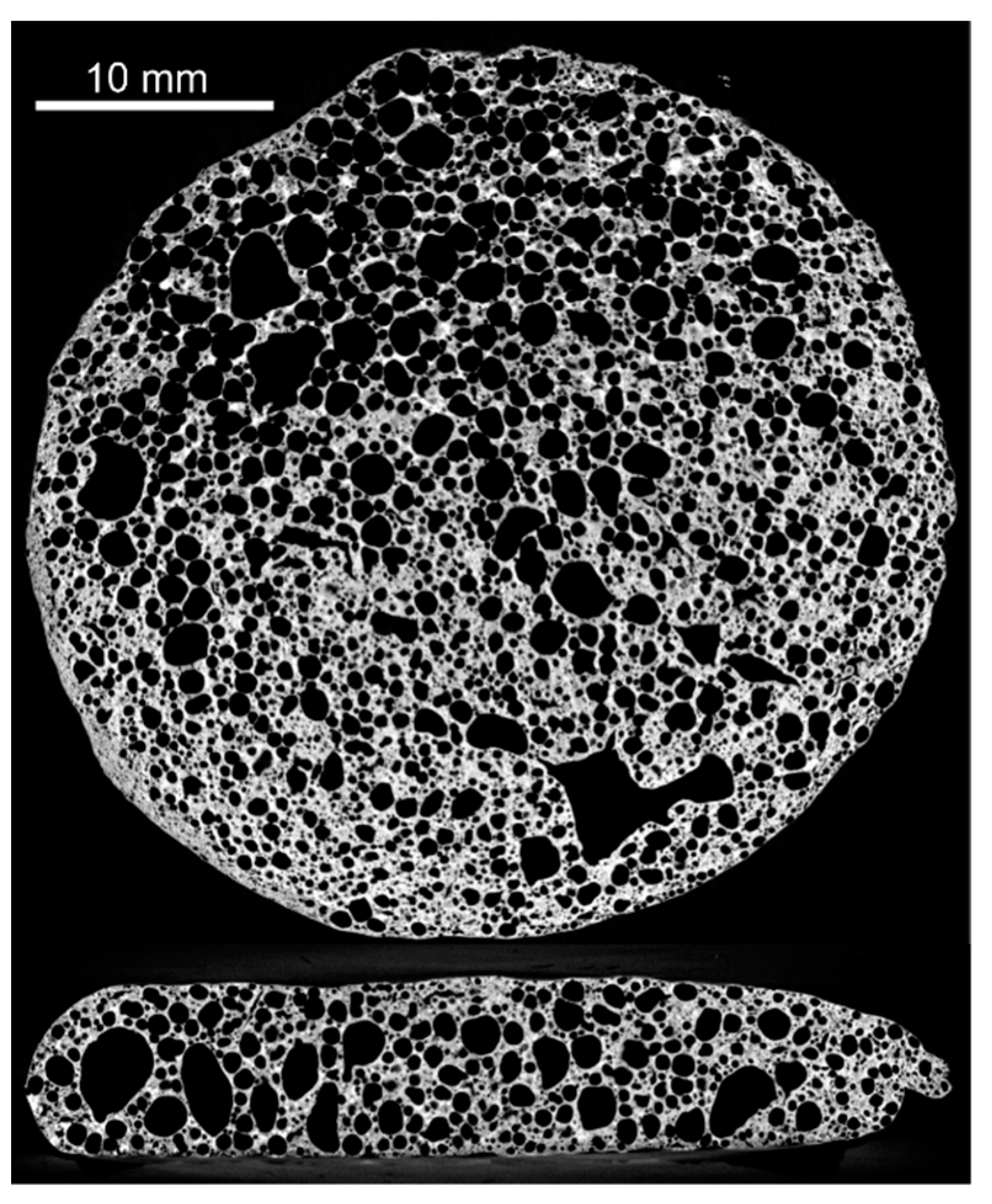
- Using particles of alloy one with a particle size <45 and >90 µm, a blowing agent content of 1.5 wt.%, a foaming temperature of 625 °C and a foaming duration of 3 min, a homogenous metal foam with a high porosity of 81% was successfully produced.
Author Contributions
Funding
Institutional Review Board Statement
Informed Consent Statement
Data Availability Statement
Conflicts of Interest
References
- Ashby, M.F. Metal Foams: A Design Guide; Butterworth-Heinemann: Boston, MA, USA, 2000; ISBN 0-7506-7219-6. [Google Scholar]
- Banhart, J. Manufacture, characterisation and application of cellular metals and metal foams. Prog. Mater. Sci. 2001, 46, 559–632. [Google Scholar] [CrossRef]
- Hipke, T.; Lange, G.; Poss, R. Taschenbuch für Aluminiumschäume, 1st ed.; Aluminium-Verl.: Düsseldorf, Germany, 2007; ISBN 978-3-87017-285-5. [Google Scholar]
- Banhart, J. Light-metal foams-history of innovation and technological challenges. Adv. Eng. Mater. 2013, 15, 82–111. [Google Scholar] [CrossRef]
- Banhart, J. 4.14 Production of Metal Foams. In Comprehensive Composite Materials II; Elsevier: Amsterdam, The Netherlands, 2018; pp. 347–363. [Google Scholar]
- Zhou, W.; Yu, J.; Lu, X.; Lin, J.; Dean, T.A. A comparative study on deformation mechanisms, microstructures and mechanical properties of wide thin-ribbed sections formed by sideways and forward extrusion. Int. J. Mach. Tools Manuf. 2021, 168, 103771. [Google Scholar] [CrossRef]
- Zhou, W.; Yu, J.; Lin, J.; Dean, T.A. Effects of die land length and geometry on curvature and effective strain of profiles produced by a novel sideways extrusion process. J. Mater. Process. Technol. 2020, 282, 116682. [Google Scholar] [CrossRef]
- Duarte, I.; Vesenjak, M.; Krstulović-Opara, L.; Anžel, I.; Ferreira, J. Manufacturing and bending behaviour of in situ foam-filled aluminium alloy tubes. Mater. Des. 2015, 66, 532–544. [Google Scholar] [CrossRef]
- Duarte, I.; Vesenjak, M.; Krstulović-Opara, L. Dynamic and quasi-static bending behaviour of thin-walled aluminium tubes filled with aluminium foam. Compos. Struct. 2014, 109, 48–56. [Google Scholar] [CrossRef]
- Plorin, T.; Bormann, D.; Heidenblut, T.; Bach, F.W. Investigations into Manufacturing Composite Profiles Having Local Magnesium-Foam Reinforcements. Adv. Mater. Res. 2010, 137, 129–160. [Google Scholar] [CrossRef] [Green Version]
- Baumeister, J.; Rausch, G.; Stöbener, K.; Lehmhus, D.; Busse, M. Verbundwerkstoffe mit Aluminiumschaum—Anwendungen im Schienenfahrzeugbau. Mater. Werkst. 2007, 38, 939–942. [Google Scholar] [CrossRef]
- Stöbener, K.; Baumeister, J.; Rausch, G.; Rausch, M. Forming metal foams by simpler methods for cheaper solutions. Met. Powder Rep. 2005, 60, 12–16. [Google Scholar] [CrossRef]
- Duarte, I.; Vesenjak, M.; Krstulović-Opara, L.; Ren, Z. Compressive performance evaluation of APM (Advanced Pore Morphology) foam filled tubes. Compos. Struct. 2015, 134, 409–420. [Google Scholar] [CrossRef]
- Vesenjak, M.; Gačnik, F.; Krstulović-Opara, L.; Ren, Z. Mechanical Properties of Advanced Pore Morphology Foam Elements. Mech. Adv. Mater. Struct. 2014, 22, 359–366. [Google Scholar] [CrossRef]
- Bauser, M.; Sauer, G.; Siegert, K. Strangpressen, 2nd ed.; Aluminium-Verl.: Düsseldorf, Germany, 2001; ISBN 3-87017-249-5. [Google Scholar]
- Nowak, M. Prozessintegrierte Abkühlung mittels Wasser-Luft-Spray-Kühlung beim Strangpressen der Aluminiumlegierungen EN AW-6082 und EN AW-Zugl. Master’s Thesis, Hannover University, Hannover, Germany, 2014. [Google Scholar]
- Thürer, S.E.; Peddinghaus, J.; Heimes, N.; Bayram, F.C.; Bal, B.; Uhe, J.; Behrens, B.-A.; Maier, H.J.; Klose, C. Lateral Angular Co-Extrusion: Geometrical and Mechanical Properties of Compound Profiles. Metals 2020, 10, 1162. [Google Scholar] [CrossRef]
- Schaffer, G.; Sercombe, T.; Lumley, R. Liquid phase sintering of aluminium alloys. Mater. Chem. Phys. 2001, 67, 85–91. [Google Scholar] [CrossRef]
- Ostermann, F. Anwendungstechnologie Aluminium; Springer: Berlin/Heidelberg, Germany, 2014; ISBN 978-3-662-43806-0. [Google Scholar]
- Altenpohl, D. Aluminium und Aluminiumlegierungen; Springer: Berlin/Heidelberg, Germany, 1965; ISBN 978-3-662-30245-3. [Google Scholar]
- Suzuki, T. Materials Science International Team, MSIT®. Calculated Liquidus Surface: Datasheet From MSI Eureka in Springer Materials; MSI, Materials Science International Services GmbH: Stuttgart, Germany, 1993; Available online: https://materials.springer.com/msi/phase-diagram/docs/sm_msi_r_10_014605_01_full_LnkDia0) (accessed on 29 May 2018).
- Usercom. Interpreting DSC curves Part 1: Dynamic measurements; Mettler Toledo GmbH, Ed.; Mettler Toledo GmbH: Schwerzenbach, Switzerland, 2000. [Google Scholar]
- Yu, C.-J.; Eifert, H.H.; Banhart, J.; Baumeister, J. Metal foaming by a powder metallurgy method: Production, properties and applications. Mater. Res. Innov. 1998, 2, 181–188. [Google Scholar] [CrossRef]
- Lehmhus, D. Beitrag zur Optimierung der Herstellung und der Materialeigenschaften von Aluminiumschäumen. Zugl. Master’s Thesis, Bremen University, Bremen, Germany, 2007. [Google Scholar]
- Dean, A.; Voss, D.; Draguljić, D. Design and Analysis of Experiments; Springer International Publishing: Cham, Switzerland, 2017; ISBN 978-3-319-52248-7. [Google Scholar]
- Siebertz, K.; van Bebber, D.; Hochkirchen, T. Statistische Versuchsplanung; Springer: Berlin/Heidelberg, Germany, 2017; ISBN 978-3-662-55742-6. [Google Scholar]
- Mrówka-Nowotnik, G.; Sieniawski, J. Influence of heat treatment on the microstructure and mechanical properties of 6005 and 6082 aluminium alloys. J. Mater. Process. Technol. 2005, 162–163, 367–372. [Google Scholar] [CrossRef]
- Birol, Y. Thixoforging experiments with 6082 extrusion feedstock. J. Alloy. Compd. 2008, 455, 178–185. [Google Scholar] [CrossRef]
- Körner, C. Foam formation mechanisms in particle suspensions applied to metal foams. Mater. Sci. Eng. A 2008, 495, 227–235. [Google Scholar] [CrossRef]
- Hirsch, J. Aluminium in Innovative Light-Weight Car Design. Mater. Trans. 2011, 52, 818–824. [Google Scholar] [CrossRef] [Green Version]
- Duarte, I.; Banhart, J. A study of aluminium foam formation—Kinetics and microstructure. Acta Mater. 2000, 48, 2349–2362. [Google Scholar] [CrossRef]
- Banhart, J. Metal Foams: Production and Stability. Adv. Eng. Mater. 2006, 8, 781–794. [Google Scholar] [CrossRef]
- Helfen, L.; Stanzick, H.; Ohser, J.; Schladitz, K.; Rejmankova-Pernot, P.; Banhart, J.; Baumbach, T. Investigation of the foaming process of metals by synchrotron radiation imaging. In NDE for Health Monitoring and Diagnostics; SPIE: Washington, DC, USA, 2003; pp. 254–265. [Google Scholar]


| Alloy No. | Designation | Zn Content (Nominal) | Si Content (Nominal) | Al Content |
|---|---|---|---|---|
| 1 | Al-Zn22-Si6 | 22.0 | 6.0 | balance |
| 2 | Al-Zn22-Si6.5 | 22.0 | 6.5 | balance |
| 3 | Al-Zn22-Si7.5 | 22.0 | 7.5 | balance |
| 4 | Al-Zn22-Si8 | 22.0 | 8.0 | balance |
| 5 | Al-Zn23.5-Si8.5 | 23.5 | 8.5 | balance |
| 6 | Al-Zn25-Si7.0 | 25.0 | 7.0 | balance |
| 7 | Al-Zn26-Si6.5 | 26.0 | 6.5 | balance |
| 8 | Al-Zn28-Si5 | 28.0 | 5.0 | balance |
| Sample | Particle Size, µm | Blowing Agent Content, wt.% | Temperature, °C | Foaming Duration, Min |
|---|---|---|---|---|
| 1 | <45 | 0.2 | 550 | 1.0 |
| 2 | <45 | 0.5 | 575 | 2.0 |
| 3 | <45 | 0.7 | 600 | 3.0 |
| 4 | <45 | 1.0 | 625 | 5.0 |
| 5 | <45 | 1.5 | 650 | 7.5 |
| 6 | 45–63 | 0.2 | 575 | 3.0 |
| 7 | 45–63 | 0.5 | 600 | 5.0 |
| 8 | 45–63 | 0.7 | 625 | 7.5 |
| 9 | 45–63 | 1.0 | 650 | 1.0 |
| 10 | 45–63 | 1.5 | 550 | 2.0 |
| 11 | 63–90 | 0.2 | 600 | 7.5 |
| 12 | 63–90 | 0.5 | 625 | 1.0 |
| 13 | 63–90 | 0.7 | 650 | 2.0 |
| 14 | 63–90 | 1.0 | 550 | 3.0 |
| 15 | 63–90 | 1.5 | 575 | 5.0 |
| 16 | 90–180 | 0.2 | 625 | 2.0 |
| 17 | 90–180 | 0.5 | 650 | 3.0 |
| 18 | 90–180 | 0.7 | 550 | 5.0 |
| 19 | 90–180 | 1.0 | 575 | 7.5 |
| 20 | 90–180 | 1.5 | 600 | 1.0 |
| 21 | <45 + >90 | 0.2 | 650 | 5.0 |
| 22 | <45 + >90 | 0.5 | 550 | 7.5 |
| 23 | <45 + >90 | 0.7 | 575 | 1.0 |
| 24 | <45 + >90 | 1.0 | 600 | 2.0 |
| 25 | <45 + >90 | 1.5 | 625 | 3.0 |
| Alloy | Designation | Zn Content in at.% | Si Content in at.% | Al Content in at.% | Theoretical Density in g/cm3 |
|---|---|---|---|---|---|
| 1 | AlZn22Si6 | 21.5 | 6.0 | balance | 3.55 |
| 2 | AlZn22Si6.5 | 21.7 | 6.5 | balance | 3.56 |
| 3 | AlZn22Si7.5 | 22.3 | 7.5 | balance | 3.58 |
| 4 | AlZn22Si8 | 21.8 | 7.9 | balance | 3.55 |
| 5 | AlZn23.5Si8.5 | 23.6 | 8.3 | balance | 3.63 |
| 6 | AlZn25Si7 | 25.1 | 7.1 | balance | 3.70 |
| 7 | AlZn26Si6.5 | 26.0 | 6.3 | balance | 3.74 |
| 8 | AlZn28Si5 | 28.2 | 5.2 | balance | 3.84 |
| Zn Content | SD | Si Content | SD | Al Content | |
|---|---|---|---|---|---|
| Top area of the cast billet | 20.1 | ±1.6 | 6.3 | ±1.2 | balance |
| Bottom area of the cast billet | 23.1 | ±2.0 | 5.4 | ±0.7 | balance |
| Average | 21.6 | 5.8 | balance |
| Element | ROI 1 | ROI 2 | ROI 3 | ROI 4 | ROI 5 | ROI 6 |
|---|---|---|---|---|---|---|
| Al | 68.2 | 65.7 | 73.3 | 67.3 | 70.0 | 69.5 |
| Zn | 25.5 | 25.3 | 17.6 | 26.1 | 22.2 | 24.6 |
| Si | 6.3 | 9.0 | 9.1 | 6.6 | 7.8 | 5.9 |
| Sample | 1 | 2 | 3 | 4 | 5 | 6 | 7 | 8 | 9 | 10 |
|---|---|---|---|---|---|---|---|---|---|---|
| Porosity P, % | 15.6 (I) | 26.8 (I) | 65.4 (II) | 76.0 (III) | 80.8 (III) | 49.9 (II) | 63.4 (II) | 78.3 (III) | 74.1 (III) | 4.8 (I) |
| Sample | 11 | 12 | 13 | 14 | 15 | 16 | 17 | 18 | 19 | 20 |
| Porosity P, % | 69.6 (III) | 56.0 (II) | 79.4 (III) | 24.1 (I) | 54.1 (II) | 61.4 (II) | 80.9 (III) | 24.6 (I) | 56.2 (II) | 64.5 (II) |
| Sample | 21 | 22 | 23 | 24 | 25 | |||||
| Porosity P, % | 76.7 (III) | 4.9 (I) | 6.5 (I) | 47.8 (I) | 81.0 (III) |
| Homogeneity Level | 1 | 2 | 3 |
|---|---|---|---|
| Representative XRM image | 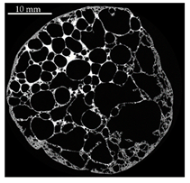 | 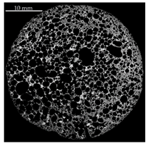 | 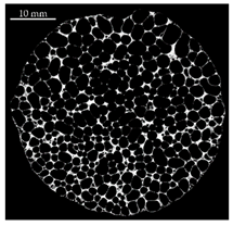 |
| Distribution of equivalent circular diameters of pore areas in the sectional view shown | 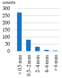 |  |  |
| Foam samples No. | 1, 3, 5 (this image), 10, 13, 14, 15, 16, 17, 18, 20, 22, 23, 24 and 25 | 2, 4, 6, 7 (this image), 8, 9, 12 and 19 | 11 and 21 (this image) |
Publisher’s Note: MDPI stays neutral with regard to jurisdictional claims in published maps and institutional affiliations. |
© 2021 by the authors. Licensee MDPI, Basel, Switzerland. This article is an open access article distributed under the terms and conditions of the Creative Commons Attribution (CC BY) license (https://creativecommons.org/licenses/by/4.0/).
Share and Cite
Schäfke, F.P.; Thürer, S.E.; Maier, H.J.; Klose, C. Development of an Aluminum-Based Hybrid Billet Material for the Process-Integrated Foaming of Hollow Co-Extrusions. Metals 2021, 11, 1382. https://doi.org/10.3390/met11091382
Schäfke FP, Thürer SE, Maier HJ, Klose C. Development of an Aluminum-Based Hybrid Billet Material for the Process-Integrated Foaming of Hollow Co-Extrusions. Metals. 2021; 11(9):1382. https://doi.org/10.3390/met11091382
Chicago/Turabian StyleSchäfke, Florian Patrick, Susanne Elisabeth Thürer, Hans Jürgen Maier, and Christian Klose. 2021. "Development of an Aluminum-Based Hybrid Billet Material for the Process-Integrated Foaming of Hollow Co-Extrusions" Metals 11, no. 9: 1382. https://doi.org/10.3390/met11091382
APA StyleSchäfke, F. P., Thürer, S. E., Maier, H. J., & Klose, C. (2021). Development of an Aluminum-Based Hybrid Billet Material for the Process-Integrated Foaming of Hollow Co-Extrusions. Metals, 11(9), 1382. https://doi.org/10.3390/met11091382