
On Modelling Parasitic Solidification Due to Heat Loss at Submerged Entry Nozzle Region of Continuous Casting Mold

 ,
,  ,
,
Abstract
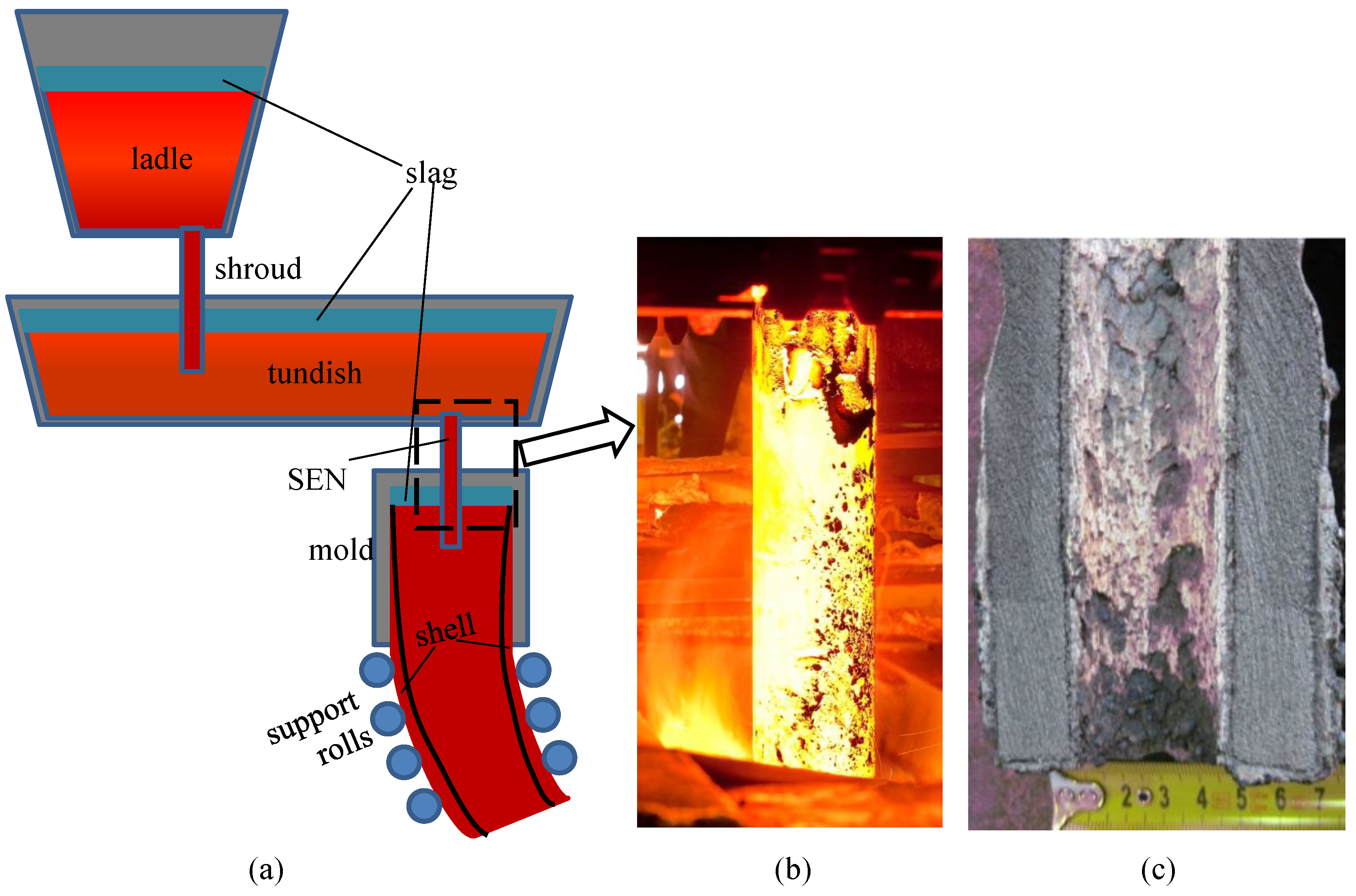
1. Introduction
2. Materials and Methods
2.1. Modelling Liquid Flow
2.2. Solidification
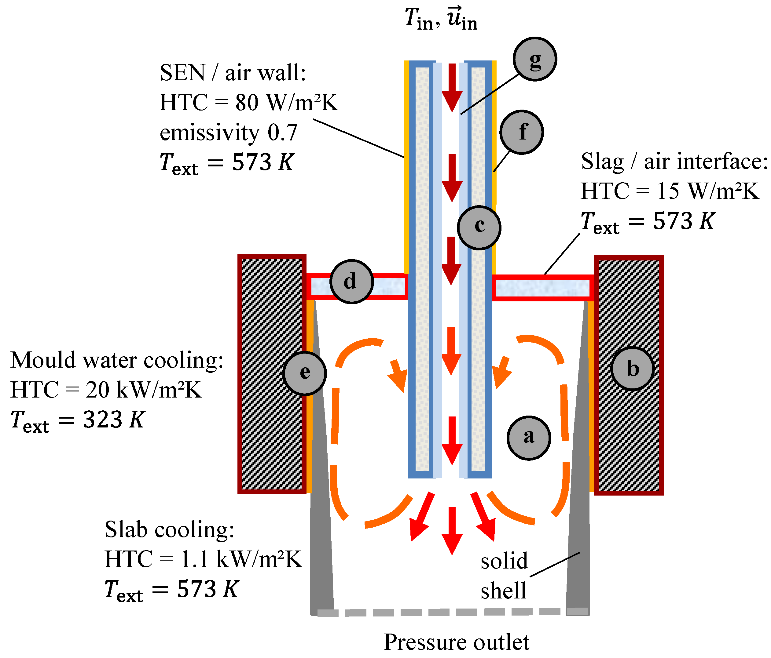
2.3. Single Mesh Approach
- It was not modified in the melt region (Figure 2a); for the rest of domain, the Darcy drag term was excluded.
- In the solid body regions including the CC mold and the refractory SEN (Figure 2b,c), the velocities in the Equation (7) were explicitly set to zero by corresponding manipulations with the matrix coefficients.
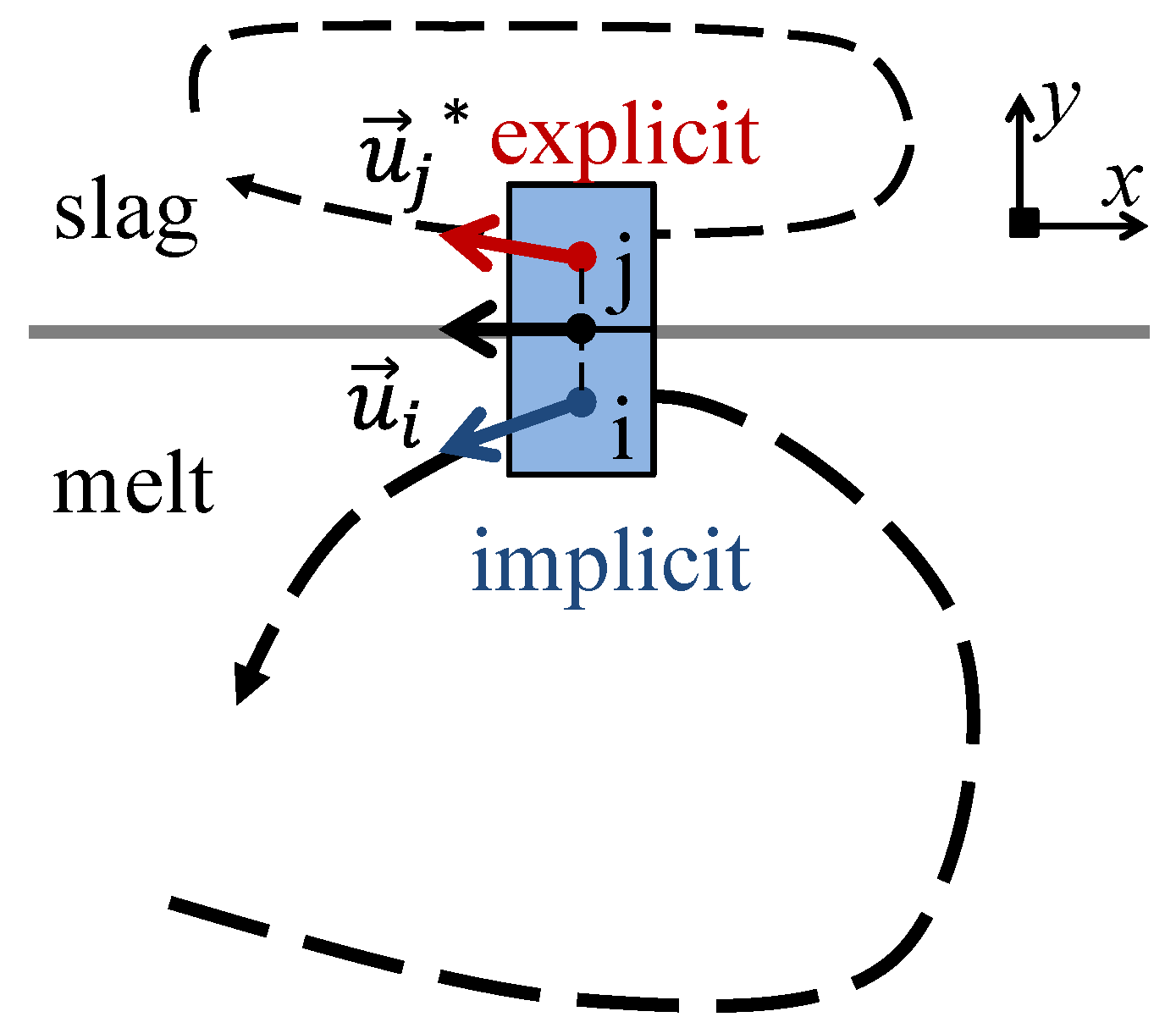
- An interface between the melt and the liquid slag (Figure 2d), where the momentum transfer was only coupled in the horizontal direction, was introduced. The implementation of an algorithm is disclosed in the next section.
2.4. Momentum Coupling at the Melt/Slag Interface
- The previous iteration velocity values were taken from the melt-side interface cells.
- They were stored for the corresponding pairs of the neighboring slag cells with the inverted vertical component, such as . The momentum flux, normal to the melt/slag interface, automatically became zero through cell-center to face-center interpolation. This approach, to some extent, reflects the ghost cell method. Simultaneously, the linear momentum, parallel to the interface, was transferred into the slag bulk due to the viscous shear stress, and recirculation zones were established.
- For all off-diagonal elements (neighboring cells), the values were multiplied by corresponding coefficients and moved to the source part in RHS.
- The diagonal and source coefficients for the slag interface cells were set to 1 and , respectively; therefore, the linear solver naturally produced aimed values . Off-diagonal coefficients were set to zero.
- After solution of the linear system (7), the melt interface values were updated and did not match the corresponding ; therefore, an iterative procedure was repeated to obtain the full convergence of the explicit and implicit parts of algorithm in Figure 3.
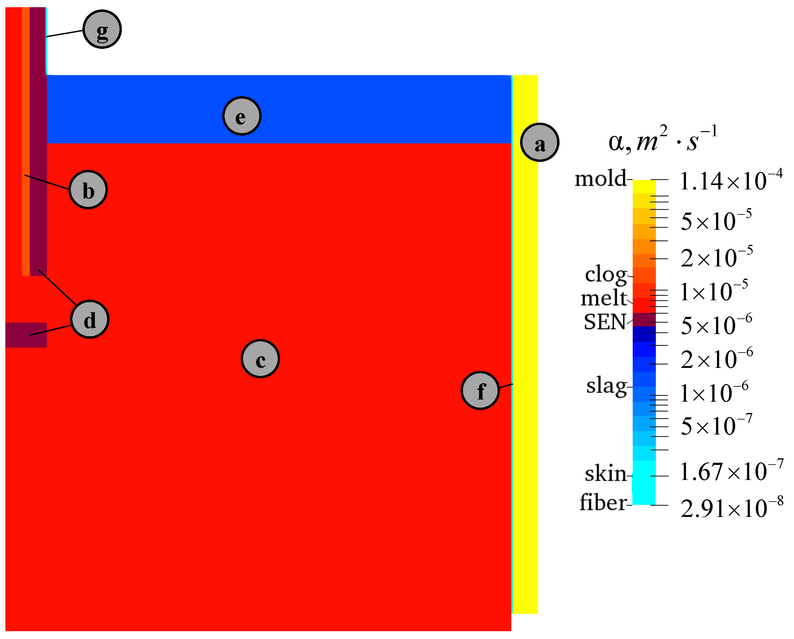
2.5. Material Properties and Case Setup
2.6. Numerical Model Performance
3. Results and Discussion
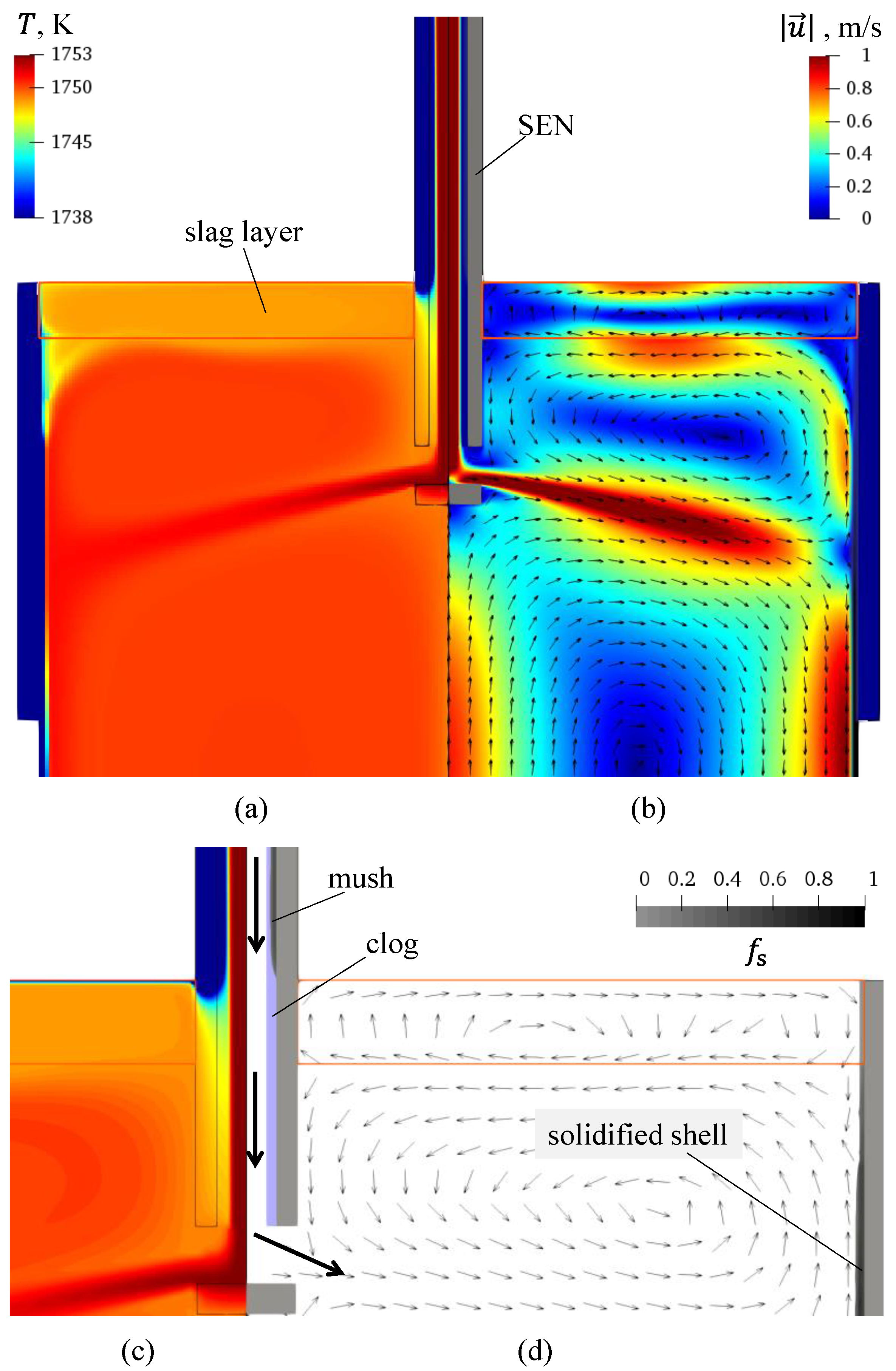
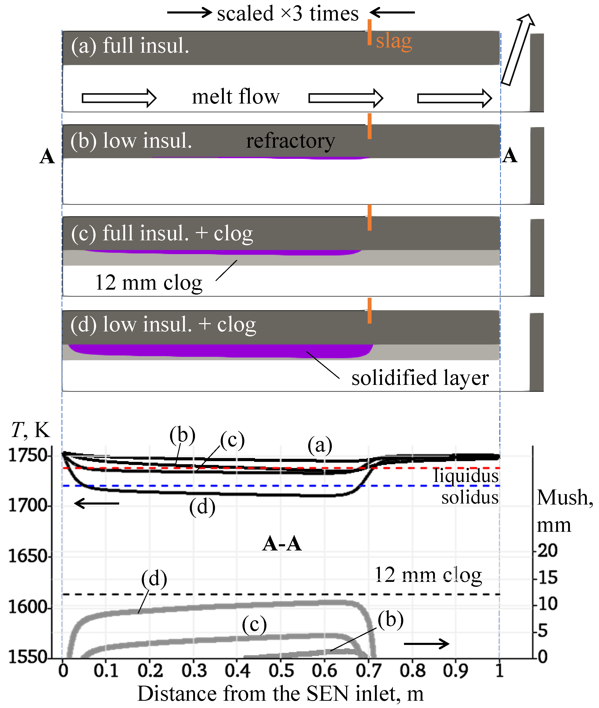
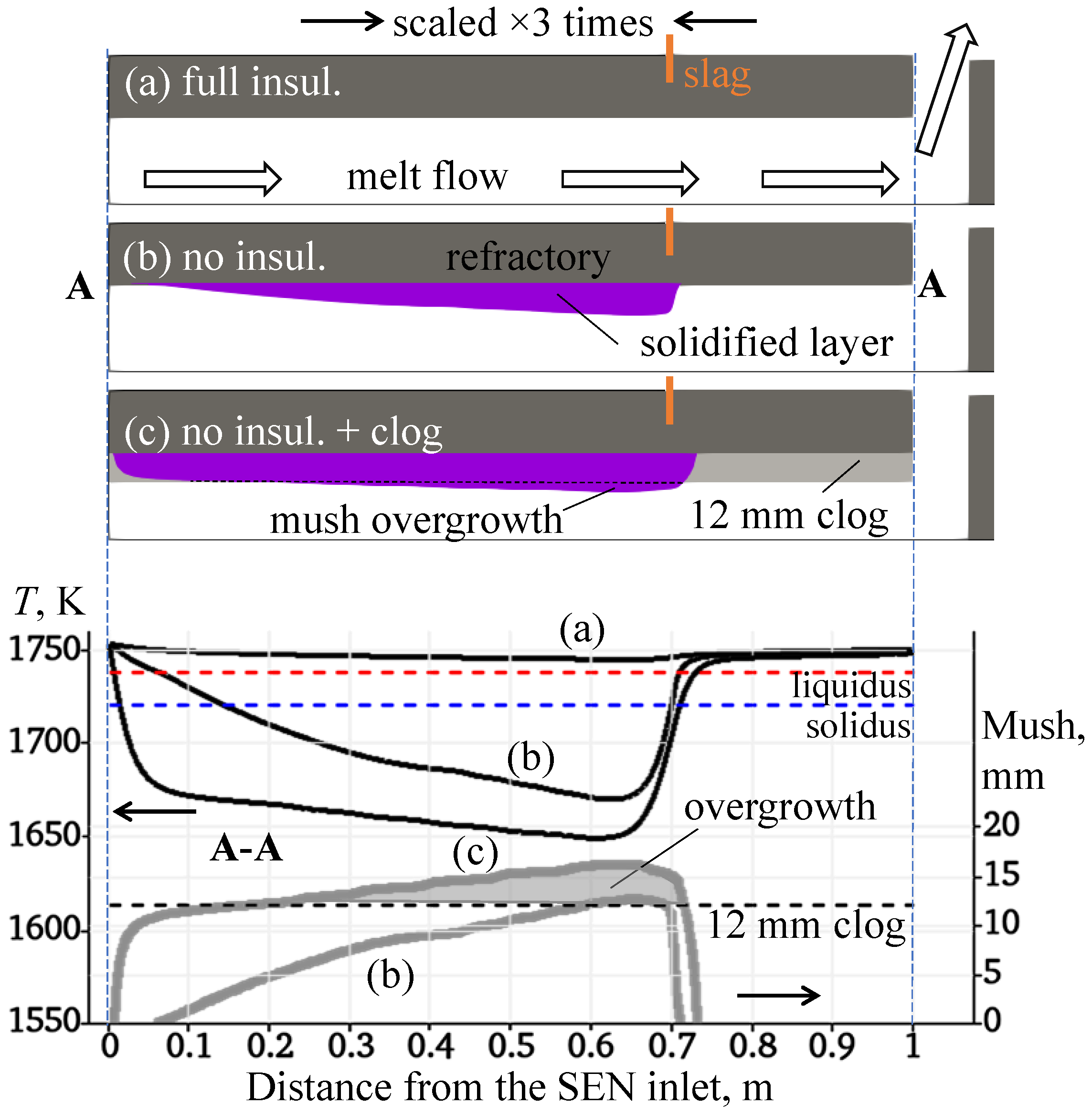
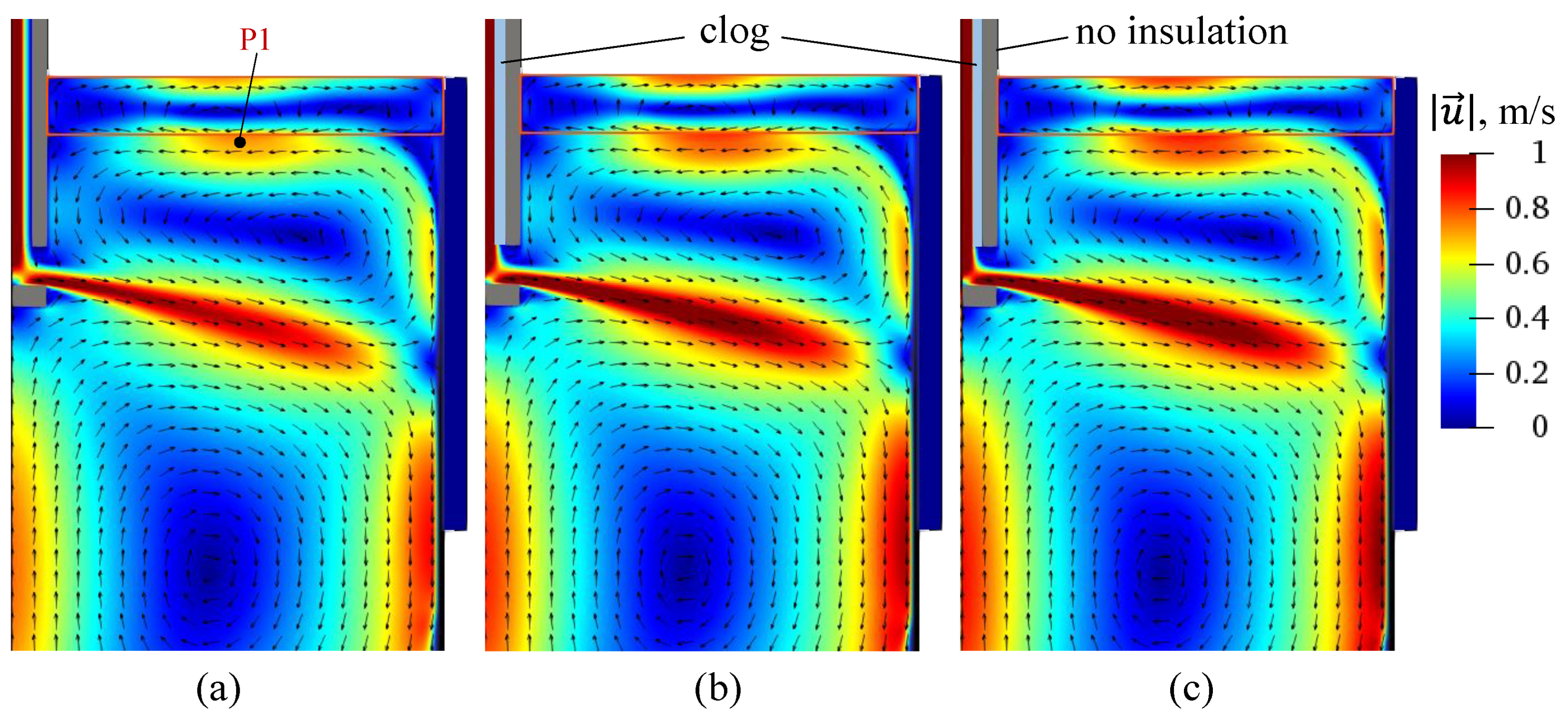
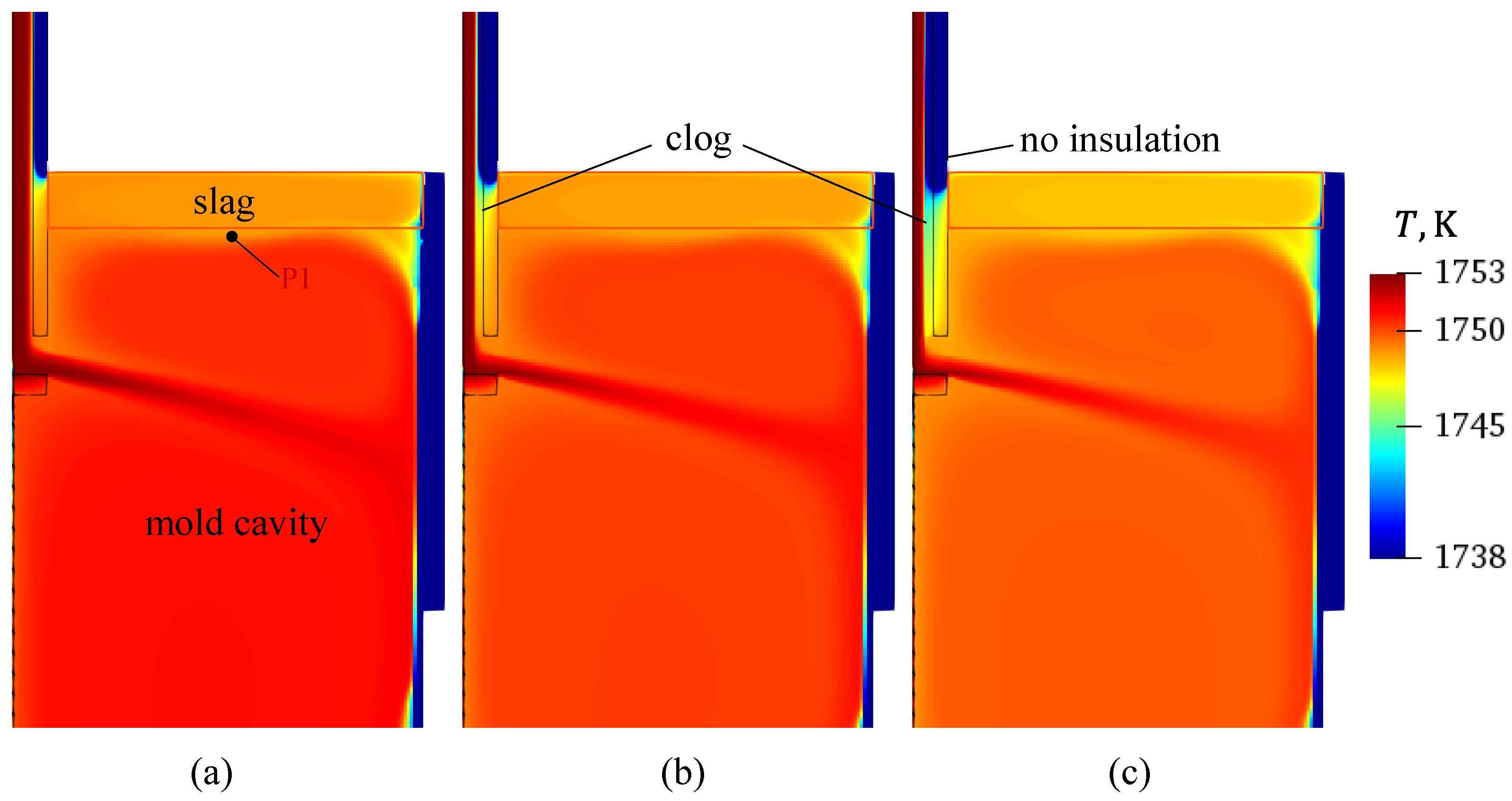
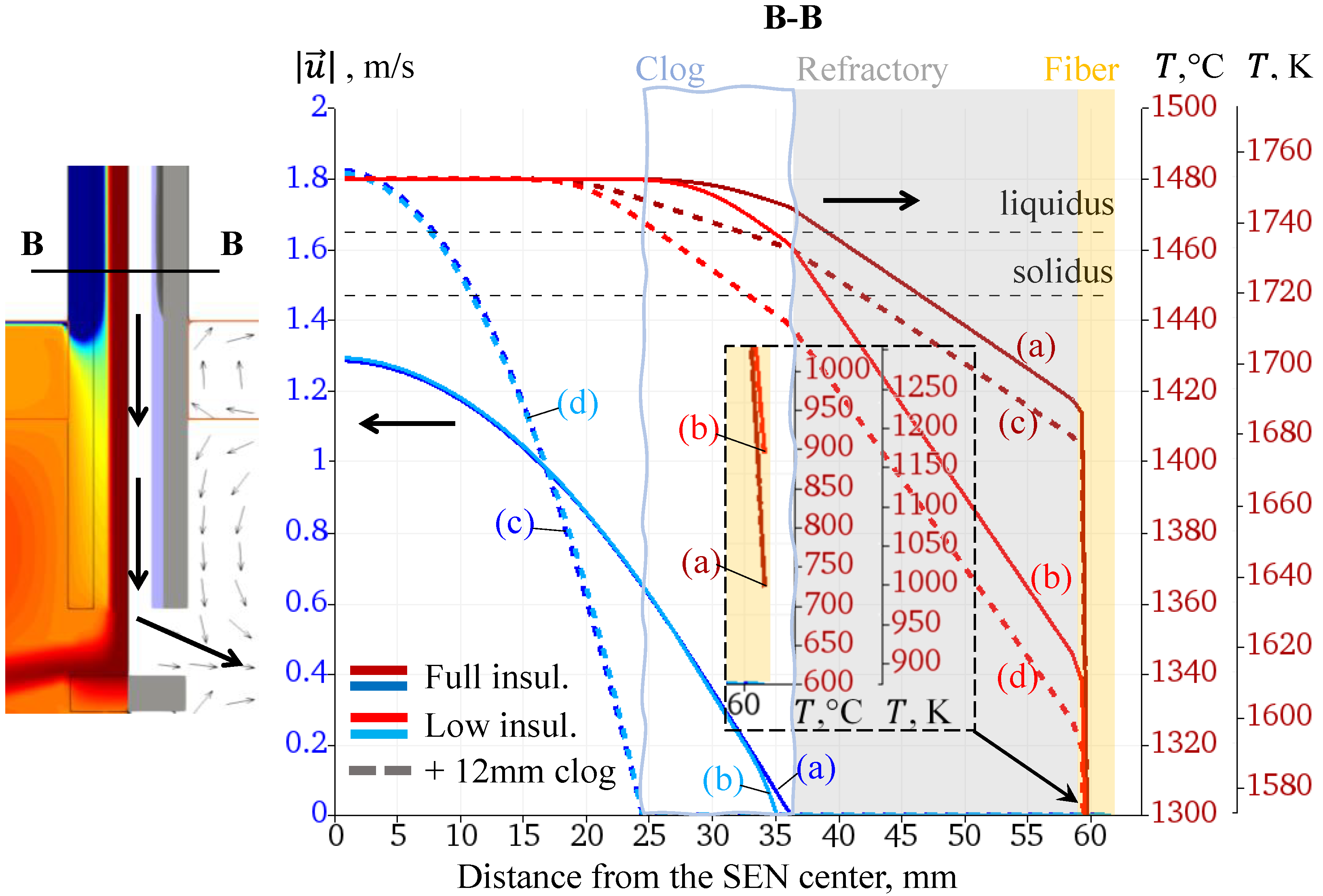
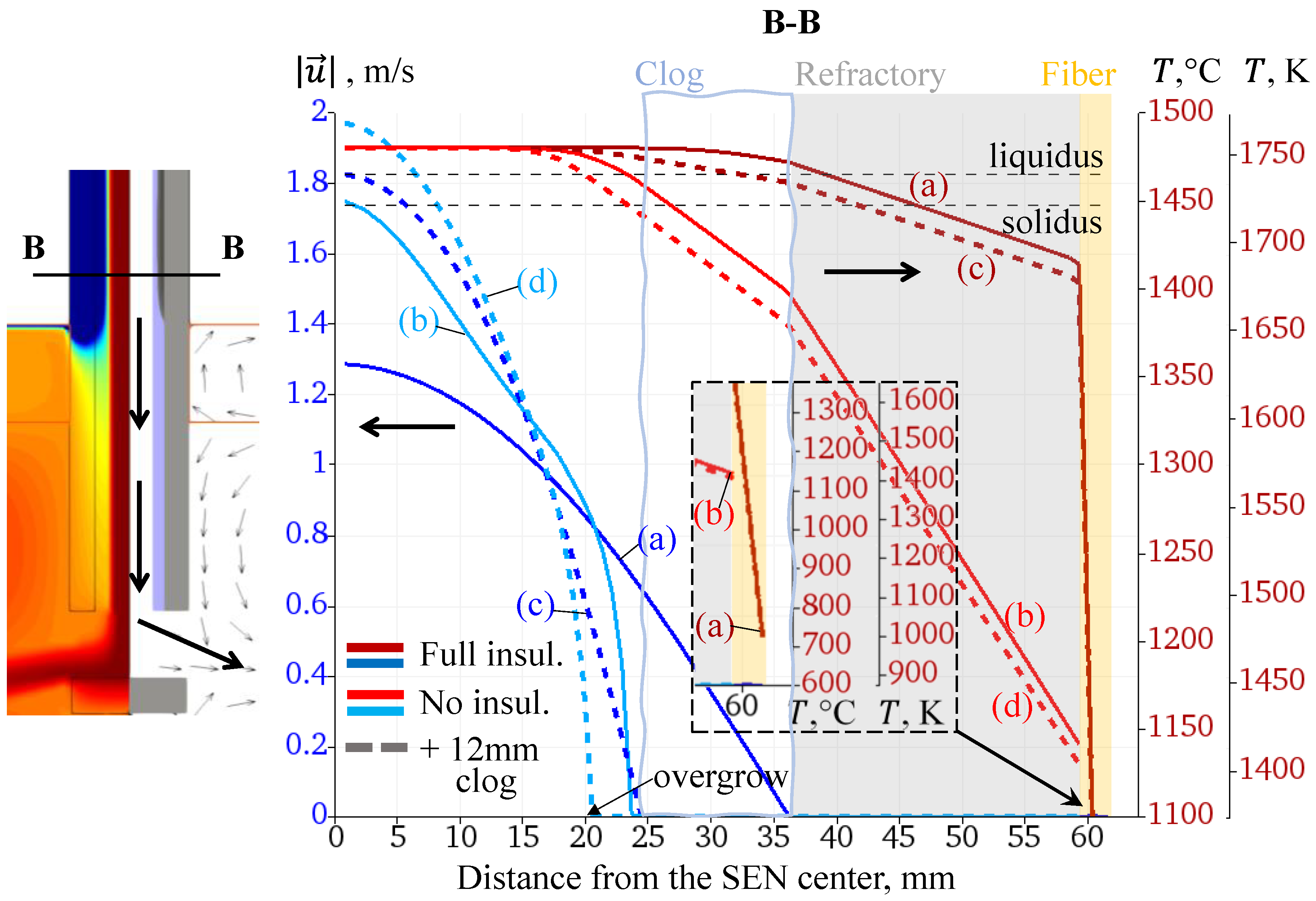
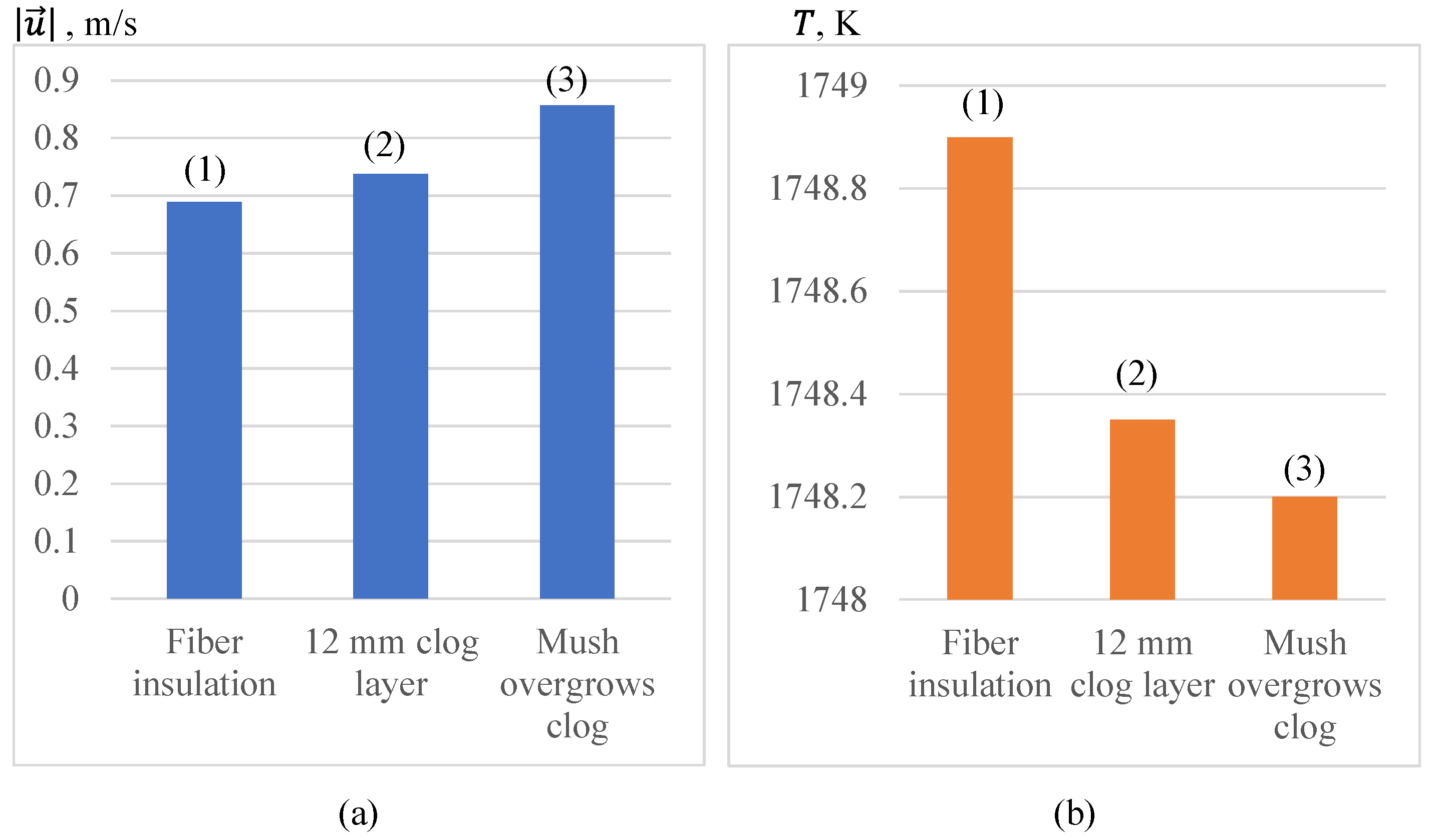
3.1. Simulation Results
3.2. Results Analysis and Discussion
4. Conclusions
Author Contributions
Funding
Institutional Review Board Statement
Informed Consent Statement
Data Availability Statement
Acknowledgments
Conflicts of Interest
References
- Vakhrushev, A.; Wu, M.; Ludwig, A.; Nitzl, G.; Tang, Y.; Hackl, G.; Wincor, R. A Water Experiment Benchmark to Evaluate Numerical Models for the Motion of Particles in Continuous Casting Tundish. Steel Res. Int. 2017, 88, 1600276. [Google Scholar] [CrossRef]
- Lopez, P.E.R.; Jalali, P.N.; Björkvall, J.; Sjöström, U.; Nilsson, C. Recent Developments of a Numerical Model for Continuous Casting of Steel: Model Theory, Setup and Comparison to Physical Modelling with Liquid Metal. ISIJ Int. 2014, 54, 342–350. [Google Scholar] [CrossRef][Green Version]
- Yang, H.; Lopez, P.E.R.; Vasallo, D.M. New Concepts for Prediction of Friction, Taper, and Evaluation of Powder Performance with an Advanced 3D Numerical Model for Continuous Casting of Steel Billets. Metall. Mater. Trans. B 2021, 52, 2760–2785. [Google Scholar] [CrossRef]
- Prescott, P.J.; Incropera, F.P. The Effect of Turbulence on Solidification of a Binary Metal Alloy With Electromagnetic Stirring. J. Heat Transf. 1995, 117, 716–724. [Google Scholar] [CrossRef]
- Voller, V.R.; Prakash, C. A Fixed Grid Numerical Modelling Methodology for Convection-Diffusion Mushy Region Phase-Change Problems. Int. J. Heat Mass Transf. 1987, 30, 1709–1719. [Google Scholar] [CrossRef]
- Voller, V.R.; Brent, A.D.; Prakash, C. The Modelling of Heat, Mass and Solute Transport in Solidification Systems. Int. J. Heat Mass Transf. 1989, 32, 1719–1731. [Google Scholar] [CrossRef]
- Voller, V.R.; Brent, A.D.; Prakash, C. Modelling the Mushy Region in a Binary Alloy. Appl. Math. Model. 1990, 14, 320–326. [Google Scholar] [CrossRef]
- Ludwig, A.; Wu, M.; Kharicha, A.; Vakhrushev, A.; Bohácek, J.; Kemminger, A.; Karimi-Sibaki, E. Process Simulation for the Metallurgical Industry: New Insights into Invisible Phenomena. BHM Berg Hüttenmänn. Mon. 2013, 158, 184–188. [Google Scholar] [CrossRef]
- Wu, M.; Vakhrushev, A.; Karimi-Sibaki, E.; Kharicha, A.; Ludwig, A. Advanced Process Simulation of Solidification and Melting. BHM Berg Hüttenmänn. Mon. 2014, 159, 30–40. [Google Scholar] [CrossRef]
- Thomas, B.G. Review on Modeling and Simulation of Continuous Casting. Steel Res. Int. 2018, 89, 1700312. [Google Scholar] [CrossRef]
- Vynnycky, M. Applied Mathematical Modelling of Continuous Casting Processes: A Review. Metals 2018, 8, 928. [Google Scholar] [CrossRef]
- Miettinen, J.; Louhenkilpi, S.; Visuri, V.-V.; Fabritius, T. Advances in Modeling of Steel Solidification with IDS. IOP Conf. Ser. Mater. Sci. Eng. 2019, 529, 012063. [Google Scholar] [CrossRef]
- Zappulla, M.L.S.; Cho, S.-M.; Koric, S.; Lee, H.-J.; Kim, S.-H.; Thomas, B.G. Multiphysics Modeling of Continuous Casting of Stainless Steel. J. Mater. Process. Technol. 2020, 278, 116469. [Google Scholar] [CrossRef]
- Kang, G.P.; Shin, G.; Kang, C.G. Development of New Model of Mold Oscillator in Continuous Casting. J. Mech. Sci. Technol. 2007, 21, 421–425. [Google Scholar] [CrossRef]
- Vynnycky, M.; Saleem, S.; Devine, K.M.; Florio, B.J.; Mitchell, S.L.; O’Brien, S.B.G. On the Formation of Fold-Type Oscillation Marks in the Continuous Casting of Steel. R. Soc. Open Sci. 2017, 4, 170062. [Google Scholar] [CrossRef] [PubMed]
- Jonayat, A.S.M.; Thomas, B.G. Transient Thermo-Fluid Model of Meniscus Behavior and Slag Consumption in Steel Continuous Casting. Metall. Mater. Trans. B 2014, 45, 1842–1864. [Google Scholar] [CrossRef]
- Lee, P.D.; Ramirez-Lopez, P.E.; Mills, K.C.; Santillana, B. Review: The “Butterfly Effect” in Continuous Casting. Ironmak. Steelmak. 2012, 39, 244–253. [Google Scholar] [CrossRef]
- Mills, K.C.; Ramirez-Lopez, P.E.; Lee, P.D. Some Insights into Mechanisms Involved in Continuous Casting. High Temp. Mater. Process. 2012, 31, 221–229. [Google Scholar] [CrossRef][Green Version]
- Mills, K.C.; Ramirez-Lopez, P.; Lee, P.D.; Santillana, B.; Thomas, B.G.; Morales, R. Looking into Continuous Casting Mould. Ironmak. Steelmak. 2014, 41, 242–249. [Google Scholar] [CrossRef]
- Jayakrishna, P.; Chakraborty, S.; Ganguly, S.; Talukdar, P. A Novel Method for Determining the Three Dimensional Variation of Non-Linear Thermal Resistance at the Mold-Strand Interface in Billet Continuous Casting Process. Int. Commun. Heat Mass Transf. 2020, 119, 104984. [Google Scholar] [CrossRef]
- Meng, Y.; Thomas, B.G. Heat-Transfer and Solidification Model of Continuous Slab Casting: CON1D. Metall. Mater. Trans. B 2003, 34, 685–705. [Google Scholar] [CrossRef]
- Bohacek, J.; Kharicha, A.; Ludwig, A.; Wu, M.; Karimi-Sibaki, E. Heat Transfer Coefficient at Cast-Mold Interface During Centrifugal Casting: Calculation of Air Gap. Metall. Mater. Trans. B 2018, 49, 1421–1433. [Google Scholar] [CrossRef]
- Hibbeler, L.C.; Chin See, M.M.; Iwasaki, J.; Swartz, K.E.; O’Malley, R.J.; Thomas, B.G. A Reduced-Order Model of Mould Heat Transfer in the Continuous Casting of Steel. Appl. Math. Model. 2016, 40, 8530–8551. [Google Scholar] [CrossRef]
- Vakhrushev, A.; Kharicha, A.; Wu, M.; Ludwig, A.; Nitzl, G.; Tang, Y.; Hackl, G.; Watziger, J.; Rodrigues, C.M.G. On Modelling Viscoplastic Behavior of the Solidifying Shell in the Funnel-Type Continuous Casting Mold. IOP Conf. Ser. Mater. Sci. Eng. 2019, 529, 012081. [Google Scholar] [CrossRef]
- Vakhrushev, A.; Kharicha, A.; Wu, M.; Ludwig, A.; Nitzl, G.; Tang, Y.; Hackl, G.; Watzinger, J.; Rodrigues, C.M.G. Modelling Viscoplastic Behavior of Solidifying Shell under Applied Electromagnetic Breaking during Continuous Casting. IOP Conf. Ser. Mater. Sci. Eng. 2020, 861, 012015. [Google Scholar] [CrossRef]
- Rodrigues, C.M.G.; Ludwig, A.; Wu, M.; Kharicha, A.; Vakhrushev, A. Impact of Crystal Sedimentation and Viscoplastic Semi-Solid Dynamics on Macrosegregation. IOP Conf. Ser. Mater. Sci. Eng. 2020, 861, 012042. [Google Scholar] [CrossRef]
- Rodrigues, C.M.G.; Ludwig, A.; Wu, M.; Kharicha, A.; Vakhrushev, A. Two-Phase Viscoplastic Model for the Simulation of Twin Roll Casting. J. Mater. Process. Technol. 2020, 286, 116814. [Google Scholar] [CrossRef]
- Rodrigues, C.M.G.; Ludwig, A.; Wu, M.; Kharicha, A.; Vakhrushev, A. A Comprehensive Analysis of Macrosegregation Formation During Twin-Roll Casting. Metall. Mater. Trans. B 2019, 50, 1334–1350. [Google Scholar] [CrossRef]
- Zhang, S.; Guillemot, G.; Gandin, C.-A.; Bellet, M. A Partitioned Solution Algorithm for Concurrent Computation of Stress–Strain and Fluid Flow in Continuous Casting Process. Metall. Mater. Trans. B 2021, 52, 978–995. [Google Scholar] [CrossRef]
- Hnizdil, M.; Kominek, J.; Lee, T.-W.; Raudensky, M.; Carnogurska, M.; Chabicovsky, M. Prediction of Leidenfrost Temperature in Spray Cooling for Continuous Casting and Heat Treatment Processes. Metals 2020, 10, 1551. [Google Scholar] [CrossRef]
- Kotrbacek, P.; Bellerova, H.; Luks, T.; Raudensky, M. Heat Transfer Correlations for Secondary Cooling in Continuous Casting. Steel Res. Int. 2021, 92, 2000465. [Google Scholar] [CrossRef]
- Bohacek, J.; Raudensky, M.; Kotrbacek, P. Remote Cooling of Rolls in Hot Rolling; Applicability to Other Processes. Metals 2021, 11, 1061. [Google Scholar] [CrossRef]
- Thomas, B.G.; Cho, S.M. Overview of Electromagnetic Forces to Control Flow During Continuous Casting of Steel. IOP Conf. Ser. Mater. Sci. Eng. 2018, 424, 012027. [Google Scholar] [CrossRef]
- Cho, S.-M.; Thomas, B.G. Electromagnetic Effects on Solidification Defect Formation in Continuous Steel Casting. JOM 2020, 72, 3610–3627. [Google Scholar] [CrossRef]
- Garcia-Hernandez, S.; Gonzalez-Guzman, C.H.; Morales Davila, R.; Barreto, J.D.J.; Gutierrez, E.; Calderon-Ramos, I. Modeling Study of EMBr Effects on the Detrimental Dynamic Distortion Phenomenon in a Funnel Thin Slab Mold. Crystals 2020, 10, 958. [Google Scholar] [CrossRef]
- Wang, C.; Liu, Z.; Li, B. Combined Effects of EMBr and SEMS on Melt Flow and Solidification in a Thin Slab Continuous Caster. Metals 2021, 11, 948. [Google Scholar] [CrossRef]
- Li, B.; Lu, H.; Zhong, Y.; Ren, Z.; Lei, Z. Influence of EMS on Asymmetric Flow with Different SEN Clogging Rates in a Slab Continuous Casting Mold. Metals 2019, 9, 1288. [Google Scholar] [CrossRef]
- Liu, Z.; Vakhrushev, A.; Wu, M.; Karimi-Sibaki, E.; Kharicha, A.; Ludwig, A.; Li, B. Effect of an Electrically-Conducting Wall on Transient Magnetohydrodynamic Flow in a Continuous-Casting Mold with an Electromagnetic Brake. Metals 2018, 8, 609. [Google Scholar] [CrossRef]
- Vakhrushev, A.; Kharicha, A.; Liu, Z.; Wu, M.; Ludwig, A.; Nitzl, G.; Tang, Y.; Hackl, G.; Watzinger, J. Electric Current Distribution During Electromagnetic Braking in Continuous Casting. Metall. Mater. Trans. B 2020, 51, 2811–2828. [Google Scholar] [CrossRef]
- Vakhrushev, A.; Kharicha, A.; Karimi-Sibaki, E.; Wu, M.; Ludwig, A.; Nitzl, G.; Tang, Y.; Hackl, G.; Watzinger, J.; Eckert, S. Generation of Reverse Meniscus Flow by Applying An Electromagnetic Brake. Metall. Mater. Trans. B 2021. [Google Scholar] [CrossRef]
- Vakhrushev, A.; Menghuai, W.; Ludwig, A.; Tang, Y.; Nitzl, G.; Hackl, G. Experimental Verification of the 3-Phase Continuous Casting Simulation Using a Water Model. In Proceedings of the 8th ECCC Conference, Graz, Austria, 23–26 June 2014. [Google Scholar] [CrossRef]
- Cho, S.-M.; Liang, M.; Olia, H.; Das, L.; Thomas, B.G. Multiphase Flow-Related Defects in Continuous Casting of Steel Slabs. In TMS 2020 149th Annual Meeting & Exhibition Supplemental Proceedings; The Minerals, Metals & Materials Society, Ed.; The Minerals, Metals & Materials Series; Springer International Publishing: Cham, Switzerland, 2020; pp. 1161–1173. ISBN 978-3-030-36295-9. [Google Scholar]
- Liu, Z.; Li, B.; Vakhrushev, A.; Wu, M.; Ludwig, A. Physical and Numerical Modeling of Exposed Slag Eye in Continuous Casting Mold Using Euler–Euler Approach. Steel Res. Int. 2019, 90, 1800117. [Google Scholar] [CrossRef]
- Saeedipour, M.; Puttinger, S.; Doppelhammer, N.; Pirker, S. Investigation on Turbulence in the Vicinity of Liquid-Liquid Interfaces—Large Eddy Simulation and PIV Experiment. Chem. Eng. Sci. 2019, 198, 98–107. [Google Scholar] [CrossRef]
- Saeedipour, M.; Vincent, S.; Pirker, S. Large Eddy Simulation of Turbulent Interfacial Flows Using Approximate Deconvolution Model. Int. J. Multiph. Flow 2019, 112, 286–299. [Google Scholar] [CrossRef]
- Liu, Z.; Vakhrushev, A.; Wu, M.; Kharicha, A.; Ludwig, A.; Li, B. Scale-Adaptive Simulation of Transient Two-Phase Flow in Continuous-Casting Mold. Metall. Mater. Trans. B 2019, 50, 543–554. [Google Scholar] [CrossRef]
- Puttinger, S.; Saeedipour, M. Time-Resolved PIV Measurements of a Deflected Submerged Jet Interacting with Liquid-Gas and Liquid-Liquid Interfaces. Exp. Comput. Multiph. Flow 2021. [Google Scholar] [CrossRef]
- Saeedipour, M.; Vincent, S.; Estivalezes, J.-L. Toward a Fully Resolved Volume of Fluid Simulation of the Phase Inversion Problem. Acta Mech. 2021, 232, 2695–2714. [Google Scholar] [CrossRef]
- Lopez, P.E.R.; Jalali, P.N.; Sjöström, U.; Jönsson, P.G.; Mills, K.C.; Sohn, I. Key Lubrication Concepts to Understand the Role of Flow, Heat Transfer and Solidification for Modelling Defect Formation during Continuous Casting. ISIJ Int. 2018, 58, 201–210. [Google Scholar] [CrossRef]
- Tang, Y.; Hackl, G.; Nitzl, G.; Seitz, P.-P.; KOŠIR, A. Simulation and Industrial Measurement of Heat Transfer of Flow Control Products with Special Inner Liner. In Proceedings of the STEELSIM 2017, Qingdao, China, 16–18 August 2017; p. 5. [Google Scholar]
- Morales, R.D.; Tang, Y.; Nitzl, G.; Eglsäumleer, C.; Hackl, G. Design of a Submerged Entry Nozzle for Thin Slab Molds Operating at High Casting Speeds. ISIJ Int. 2012, 52, 1607–1615. [Google Scholar] [CrossRef]
- Mozhzherin, V.A.; Sakulin, V.Y.; Migal’, V.P.; Margishvili, A.P.; Konstantinov, A.A. Refractory Objects and Materials for Continuous Steel Casting. Refract. Ind. Ceram. 2008, 49, 245–250. [Google Scholar] [CrossRef]
- Ewing, H.C.; Hendry, A.; Nash, D.H. Finite Element Analysis Applied to Redesign of Submerged Entry Nozzles for Steelmaking. Proc. Inst. Mech. Eng. Part J Mater. Des. Appl. 2011, 225, 327–339. [Google Scholar] [CrossRef]
- Lee, G.-G.; Thomas, B.G.; Kim, S.-H. Effect of Refractory Properties on Initial Bubble Formation in Continuous-Casting Nozzles. Met. Mater. Int. 2010, 16, 501–506. [Google Scholar] [CrossRef]
- Wu, M.; Vakhrushev, A.; Ludwig, A.; Kharicha, A. Influence of Forced Convection on Solidification and Remelting in the Developing Mushy Zone. IOP Conf. Ser. Mater. Sci. Eng. 2016, 117, 012045. [Google Scholar] [CrossRef]
- Wu, M.; Vakhrushev, A.; Nummer, G.; Pfeiler, C.; Kharicha, A.; Ludwig, A. Importance of Melt Flow in Solidifying Mushy Zone. Open Transp. Phenom. J. 2010, 2, 16–23. [Google Scholar] [CrossRef]
- Hua, C.; Wang, M.; Senk, D.; Wang, H.; Zhang, Q.; Zhi, J.; Bao, Y. Cone Clogging of Submerged Entry Nozzle in Rare Earth Treated Ultra-Low Carbon Al-Killed Steel and Its Effect on the Flow Field and Vortex in the Mold. Metals 2021, 11, 662. [Google Scholar] [CrossRef]
- Gutiérrez, E.; Barreto, J.D.J.; Garcia-Hernandez, S.; Morales, R.; González-Solorzano, M.G. Decrease of Nozzle Clogging through Fluid Flow Control. Metals 2020, 10, 1420. [Google Scholar] [CrossRef]
- González-Solórzano, M.G.; Morales, R.D.; Gutiérrez, E.; Guarneros, J.; Chattopadhyay, K. Analysis of Fluid Flow of Liquid Steel through Clogged Nozzles: Thermodynamic Analysis and Flow Simulations. Steel Res. Int. 2020, 91, 2000049. [Google Scholar] [CrossRef]
- Li, W.; Wang, Y.; Wang, W.; Ren, Y.; Zhang, L. Dependence of the Clogging Possibility of the Submerged Entry Nozzle during Steel Continuous Casting Process on the Liquid Fraction of Non-Metallic Inclusions in the Molten Al-Killed Ca-Treated Steel. Metals 2020, 10, 1205. [Google Scholar] [CrossRef]
- Barati, H.; Wu, M.; Kharicha, A.; Ludwig, A. A Transient Model for Nozzle Clogging. Powder Technol. 2018, 329, 181–198. [Google Scholar] [CrossRef]
- Barati, H.; Wu, M.; Kharicha, A.; Ludwig, A. Calculation Accuracy and Efficiency of a Transient Model for Submerged Entry Nozzle Clogging. Metall. Mater. Trans. B 2019, 50, 1428–1443. [Google Scholar] [CrossRef]
- Barati, H.; Wu, M.; Kharicha, A.; Ludwig, A. Discussion on Possible Solidification during SEN Clogging in Steel Continuous Casting. In Proceedings of the Solidification and Gravity VII; Roósz, G.K.A., Veres, Z., Svéda, M., Eds.; Hungarian Academy of Sciences: Miskolc-Lillafüred, Hungary, 2018; pp. 144–149. [Google Scholar]
- Barati, H.; Wu, M.; Kharicha, A.; Ludwig, A. Role of Solidification in Submerged Entry Nozzle Clogging During Continuous Casting of Steel. Steel Res. Int. 2020, 91, 2000230. [Google Scholar] [CrossRef]
- Zhang, H.; Wang, W. Mold Simulator Study of Heat Transfer Phenomenon During the Initial Solidification in Continuous Casting Mold. Metall. Mater. Trans. B 2017, 48, 779–793. [Google Scholar] [CrossRef]
- Zappulla, M.L.S.; Thomas, B.G. Simulation of Longitudinal Surface Defect in Steel Continuous Casting. IOP Conf. Ser. Mater. Sci. Eng. 2020, 861, 012016. [Google Scholar] [CrossRef]
- Lichtenegger, T.; Pirker, S. Recurrence CFD—A Novel Approach to Simulate Multiphase Flows with Strongly Separated Time Scales. Chem. Eng. Sci. 2016, 153, 394–410. [Google Scholar] [CrossRef]
- Lichtenegger, T.; Pirker, S. Extremely Fast Simulations of Heat Transfer in Fluidized Beds. arXiv 2017, arXiv:1706.05934. [Google Scholar]
- Lichtenegger, T.; Peters, E.A.J.F.; Kuipers, J.A.M.; Pirker, S. A Recurrence CFD Study of Heat Transfer in a Fluidized Bed. Chem. Eng. Sci. 2017, 172, 310–322. [Google Scholar] [CrossRef]
- Pirker, S.; Lichtenegger, T. Efficient Time-Extrapolation of Single- and Multiphase Simulations by Transport Based Recurrence CFD (RCFD). Chem. Eng. Sci. 2018, 188, 65–83. [Google Scholar] [CrossRef]
- Pirker, S.; Puttinger, S.; Rössler, R.; Lichtenegger, T. Steel Alloy Homogenization During Rheinsahl–Heraeus Vacuum Treatment: Conventional Computational Fluid Dynamics, Recurrence Computational Fluid Dynamics, and Plant Observations. Steel Res. Int. 2020, 91, 2000214. [Google Scholar] [CrossRef]
- Lichtenegger, T.; Pirker, S. Toward Data-Assisted Particle-Fluid Simulations of Heat Transfer in Blast Furnaces. Steel Res. Int. 2020, 91, 2000132. [Google Scholar] [CrossRef]
- Bohacek, J.; Kharicha, A.; Ludwig, A.; Wu, M.; Holzmann, T.; Karimi-Sibaki, E. A GPU Solver for Symmetric Positive-Definite Matrices vs. Traditional Codes. Comput. Math. Appl. 2019, 78, 2933–2943. [Google Scholar] [CrossRef]
- Koric, S.; Abueidda, D.W. Deep Learning Sequence Methods in Multiphysics Modeling of Steel Solidification. Metals 2021, 11, 494. [Google Scholar] [CrossRef]
- Chen, H.; Chen, D.; Long, M.; Duan, H.; Huang, Y.; Gui, L. Numerical Modeling of Centerline Segregation by a Combined 3-D and 2-D Hybrid Model during Slab Continuous Casting. J. Mater. Res. 2018, 33, 989–1002. [Google Scholar] [CrossRef]
- Long, M.; Chen, H.; Chen, D.; Yu, S.; Liang, B.; Duan, H. A Combined Hybrid 3-D/2-D Model for Flow and Solidification Prediction during Slab Continuous Casting. Metals 2018, 8, 182. [Google Scholar] [CrossRef]
- Mitchell, S.L.; Vynnycky, M. Verified Reduction of a Model for a Continuous Casting Process. Appl. Math. Model. 2017, 48, 476–490. [Google Scholar] [CrossRef]
- Zappulla, M.L.S.; Cho, S.; Thomas, B.G. Visualization of Steel Continuous Casting Including a New Integral Method for Post-Processing Temperature Data. Steel Res. Int. 2019, 90, 1800540. [Google Scholar] [CrossRef]
- Vakhrushev, A.; Wu, M.; Ludwig, A.; Tang, Y.; Hackl, G.; Nitzl, G. Numerical Investigation of Shell Formation in Thin Slab Casting of Funnel-Type Mold. Metall. Mater. Trans. B 2014, 45, 1024–1037. [Google Scholar] [CrossRef]
- Kurz, W.; Fisher, D.J. Fundamentals of Solidification, 4th rev. ed.; Enfield, N.H., Ed.; Trans Tech Publications: Uetikon-Zuerich, Switzerland, 1998; ISBN 978-0-87849-804-8. [Google Scholar]
- Miettinen, J.; Louhenkilpi, S.; Kytönen, H.; Laine, J. IDS: Thermodynamic–Kinetic–Empirical Tool for Modelling of Solidification, Microstructure and Material Properties. Math. Comput. Simul. 2010, 80, 1536–1550. [Google Scholar] [CrossRef]
- Weller, H.G.; Tabor, G.; Jasak, H.; Fureby, C. A Tensorial Approach to Computational Continuum Mechanics Using Object-Oriented Techniques. Comput. Phys. 1998, 12, 620. [Google Scholar] [CrossRef]


| Component Material | Density (kg·m−3) | Specific Heat (J·kg−1·K−1) | Thermal Conductivity (W·m−1·K−1) | Thermal Diffusivity (m−2·s−1) | Dynamic Viscosity (kg·m−1·s−1) |
|---|---|---|---|---|---|
| Melt [81] | 7020 | 700 | 36.4 | 7.41 × 10⁻⁶ | 0.006 |
| Copper mold | 8980 | 380 | 390.0 | 1.14 × 10⁻⁴ | |
| Refractory [64] | 2430 | 1416 | 18.0 | 5.23 × 10⁻⁶ | |
| Liquid slag | 2700 | 1250 | 4.0 | 1.11 × 10⁻⁶ | 0.002 |
| Slag skin | 3000 | 1000 | 0.5 | 1.67 × 10⁻⁷ | |
| Clog [64] | 3700 | 700 | 35.0 | 1.35 × 10⁻⁵ |
| Parameter | Value |
|---|---|
| , K | 1723 |
| , K | 1738 |
| , K | 1753 |
| , m∙min−1 | 2.4 |
| Mold width, mm | 1500 |
| Copper plate, mm | 40 |
| SEN inner/outer radius, mm | 36/62 |
| SEN immerse depth, mm | 200 |
| Clog layer thickness, mm | 0 or 12 |
Publisher’s Note: MDPI stays neutral with regard to jurisdictional claims in published maps and institutional affiliations. |
© 2021 by the authors. Licensee MDPI, Basel, Switzerland. This article is an open access article distributed under the terms and conditions of the Creative Commons Attribution (CC BY) license (https://creativecommons.org/licenses/by/4.0/).
Share and Cite
Vakhrushev, A.; Kharicha, A.; Wu, M.; Ludwig, A.; Tang, Y.; Hackl, G.; Nitzl, G.; Watzinger, J.; Bohacek, J. On Modelling Parasitic Solidification Due to Heat Loss at Submerged Entry Nozzle Region of Continuous Casting Mold. Metals 2021, 11, 1375. https://doi.org/10.3390/met11091375
Vakhrushev A, Kharicha A, Wu M, Ludwig A, Tang Y, Hackl G, Nitzl G, Watzinger J, Bohacek J. On Modelling Parasitic Solidification Due to Heat Loss at Submerged Entry Nozzle Region of Continuous Casting Mold. Metals. 2021; 11(9):1375. https://doi.org/10.3390/met11091375
Chicago/Turabian StyleVakhrushev, Alexander, Abdellah Kharicha, Menghuai Wu, Andreas Ludwig, Yong Tang, Gernot Hackl, Gerald Nitzl, Josef Watzinger, and Jan Bohacek. 2021. "On Modelling Parasitic Solidification Due to Heat Loss at Submerged Entry Nozzle Region of Continuous Casting Mold" Metals 11, no. 9: 1375. https://doi.org/10.3390/met11091375
APA StyleVakhrushev, A., Kharicha, A., Wu, M., Ludwig, A., Tang, Y., Hackl, G., Nitzl, G., Watzinger, J., & Bohacek, J. (2021). On Modelling Parasitic Solidification Due to Heat Loss at Submerged Entry Nozzle Region of Continuous Casting Mold. Metals, 11(9), 1375. https://doi.org/10.3390/met11091375