Abstract
The present work is focused on a comparative study of the effect of Ti-Al interlayers and Ta alloying on the mechanical behavior of Ti1−xAlxN coatings under normal contact pressure and in-plane straining. The contact loading of the samples was carried out by scratch testing, while the in-plane tensile straining was performed by uniaxial tension of the coated steel substrates. The Ti0.45Al0.55N and Ti0.43Al0.45Ta0.12N monolithic coatings as well as the Ti0.45Al0.55N/Ti0.45Al0.55 multilayer coatings with different number and thickness of the layers were deposited by DC magnetron sputtering. It was found that the introduction of the ductile Ti0.45Al0.55 layers into the Ti0.45Al0.55N coating and alloying with Ta led to their significant toughening. The improved toughness of the Ti0.43Al0.45Ta0.12N coating coupled with high residual compressive stress and high hardness resulted in its strongest resistance to cracking under scratching and tensile straining among the coatings studied. The multilayer coating with the thickest metal layers exhibited the improved resistance to delamination under in-plane straining.
1. Introduction
Deposition of hard protective coatings on the surface of metals and alloys is one of the most advanced techniques to substantially enhance their resistance to wear, oxidation, corrosion, erosion, etc. [1]. In particular, Ti1−xAlxN coatings have been extensively used in many industrial applications due to their excellent hardness, thermal stability and oxidation resistance [2,3,4,5,6]. For example, Ti1−xAlxN coatings deposited onto nitrided AISI H11 steel substrates increased the hardness from 10 to 30 GPa and decreased the wear coefficient by 50% [6]. TiN and Ti-Al-N based coatings reduced the steady-state creep rate of the Ti-6Al-4V by an order of magnitude [7]. However, the inherent brittleness of Ti1−xAlxN solid solutions [8,9,10] restricts their potential application because of possible cracking, spallation and wear of the coatings, which inevitably results in cracking, oxidation, and corrosion of the underlying metal substrates, significantly limiting durability and reliability of structures and components [11,12,13,14,15]. Therefore, improvement of toughness of Ti-Al-N based coatings is of crucial importance for increasing their performance.
Two main strategies have been proposed to enhance toughness of hard protective coatings. The first conception implies designing of the multilayer coating architecture, which combines alternating layers of different materials [16,17,18]. The main mechanisms, which provide energy dissipation, and therefore toughening of the multilayer coatings, are: (i) crack deflection at interfaces between layers, (ii) interface ‘opening’ or delamination reducing the stress concentration, and (iii) crack tip blunting due to nanoplasticity at the interfaces. The effective way to improve the toughness of hard coatings can be the deposition of alternating ceramic and metal layers. In addition to the above-mentioned benefits, the ductile metal layers allow partial stress relaxation in the hard ceramic layers, while their plastic flow substantially increases the amount of strain energy dissipated during cracking of the multilayer coatings [14,19,20,21,22,23,24]. Another strategy consists in alloying binary and ternary compositions with additional chemical elements, which changes their electronic structure and chemical bonding. It has been shown that the key properties of the Ti1−xAlxN coatings, including the hardness and toughness, can be improved by alloying with transition metals of III–VI groups (V, Cr, Y, Zr, Nb, Mo, Hf, Ta, and W), which atoms substitute Ti or Al at the metal sublattice resulting in a huge variety of different electronic configurations [8,9,25,26,27,28,29,30].
Which strategy is more appropriate for enhancing the toughness of hard coatings depends on many factors such as the materials of the coating and substrate, coating thickness, environmental conditions, loading conditions, etc. Both introduction of soft metal layers and alloying with additional chemical elements can result in decreasing the hardness and stiffness of hard coatings that necessarily leads to reduction of their load-bearing capacity [8,19,20,24,28]. In the case of a hard coating on a softer and more compliant metal substrate subjected to normal contact pressure, the mechanical performance of the coating-substrate system can be strongly restricted by its insufficient load-bearing capacity, which furthers large out-of-plane deformation of the system, and consequently coating cracking and delamination [31]. However, it is not so important under in-plane strains, when the main failure mechanisms of the system are concerned with the interface debonding [32,33,34,35].
The motivation of the present work is a comparative study of the influence of Ti-Al interlayers and Ta alloying on the mechanical behavior of Ti1−xAlxN coatings under normal contact pressure and in-plane straining. According to the recent studies, the Ti-Al interlayers provide the strong bonding between the Ti-Al-N layers and Ti-Al-N/Ti-Al coatings are characterized by the high hardness and Young’s modulus [36,37]. Addition of Ta to Ti1−xAlxN is beneficial for its toughness enhancement with retaining the hardness [38,39]. The contact loading of the samples was carried out by scratch testing, which is commonly used to evaluate crack resistance and load-bearing capacity of coatings as well as their adhesion strength to the substrates [40,41]. The in-plane straining was performed by tensile testing of the coated substrates, which was extensively utilized to study the cracking behavior of brittle coatings on ductile substrates [42,43,44].
2. Materials and Methods
The deposition of the Ti-Al-N monolithic and Ti-Al-N/Ti-Al multilayer coatings was performed by DC magnetron sputtering using a planar circular magnetron with a Ti-Al target (55/45 at %) 125 mm in diameter. The Ti-Al-Ta-N monolithic coatings were deposited by DC magnetron co-sputtering using the magnetron with the Ti-Al target and a circular magnetron with a Ta target (99.99% purity) 100 mm in diameter. The coatings were deposited on stainless steel and Si substrates. The steel substrates were subjected to preliminary mechanical grinding and polishing. Prior to the coating deposition all the substrates were ultrasonically cleaned in rectified alcohol and sputter-cleaned with Ar+ ions at an operating pressure of 0.2 Pa for 20 min followed by the deposition of a 30 nm thick Ti-Al adhesion layer. The Ti-Al-N and Ti-Al-Ta-N layers were deposited in a mixed Ar + N2 reactive atmosphere at a total pressure of 0.3 Pa and a partial pressure of nitrogen of 0.06 Pa. In the case of the multilayer coatings, the nitrogen flow was terminated after the deposition of each Ti-Al-N layer and the substrates were shielded by a shutter for one minute to prevent nitriding of the Ti-Al layers. The Ti-Al layers were deposited in Ar atmosphere at a pressure of 0.3 Pa. The target power density was maintained at 11.4 W/cm2 for the Ti-Al target and 3.8 W/cm2 for the Ta target. The substrate temperature was 425 °C. Three Ti-Al-N/Ti-Al multilayers with 7 and 21 layers referred to as ML1, ML2, and ML3 were prepared. The thickness of the Ti-Al-N layers was varied from 0.21 to 0.6 µm, while the thickness of the Ti-Al layers was changed from 0.07 to 0.6 µm (see Table 1 for more details). Thus, the Ti-Al-Ta-N/Ti-Al thickness ratio was varied from 3:1 to 1:2. The total thickness of all the coatings was 3.0 µm.

Table 1.
Number and thickness of layers, and mechanical properties of the coatings.
The thickness and the elemental composition of the coatings were determined with a Carl Zeiss EVO 50 scanning electron microscope (SEM, Carl Zeiss, Jena, Germany) equipped with an Inca ACT-X energy-dispersive spectroscopy (EDS) detector (Oxford Instruments, High Wycombe, UK). Structural analysis of the coatings was performed by X-ray diffraction (XRD) in the Bragg-Brentano geometry with an XRD 6000 diffractometer (Shimadzu, Kyoto, Japan). The measurements were performed using CuKα radiation (λ = 1.5406 Å). The XRD peaks were recorded over the range of diffraction angles 2θ extending from 32 to 50°.
The mechanical characteristics of the coatings were determined by instrumented nanoindentation with a NanoTest system (Micro Materials Ltd., Wrexham, UK) operated in the load-controlled mode using a Berkovich diamond tip. The loading and unloading times were set at 20 s with 10 s dwell time at the maximum load and 60 s dwell time at 90% unloading for thermal drift correction. The maximum applied load was set at 20 mN to ensure penetration depths below 10% of the coating thickness in order to exclude the substrate effect on the measured mechanical characteristics. The hardness (H) and reduced elastic modulus (E*) of the coatings were determined from load vs. displacement curves using the Oliver–Pharr method [45]. The residual stresses (σR) were extracted from wafer curvature measurements of the coatings deposited on Si substrates using the Stoney equation [46].
The scratch tests were performed with a Revetest scratch tester (CSM instruments, Peseux, Switzerland) using a conical Rockwell indenter with an apex angle of 120° and a tip curvature radius of 200 µm. Three tests were carried out for each sample. The scratches were made 10 mm long with a sliding speed of 2 mm/min and a loading rate of 6 N/min. The maximum applied normal force was 30 N. The friction coefficient (µ) and the acoustic emission signals (AE) were recorded during the tests. Each failure event during scratching such as cracking and delamination of a coating results in acoustic emission output induced by the generation of transient elastic waves produced by a sudden redistribution of stresses. The magnitude of an AE signal is proportional to the area of a crack generating the signal. Three critical loads were determined to characterize the coating failure during scratching. The first critical load (Lc1) corresponded to the first crack event inside the scratch tracks. The second critical load (Lc2) was identified as the load at which the first sporadic local delamination of the coatings with substrate exposure occurred inside the tracks. The third critical load (Lc3) was attributed to the beginning of the continuous delamination of the coatings. The critical loads were determined by monitoring the coating failure using the acoustic emission technique and fluctuations of the friction coefficient with the following confirmation by optical microscopy and scanning electron microscopy. The examination of the resulting scratch grooves was carried out using an Axiovert 40 Mat microscope (Carl Zeiss, Jena, Germany) and a Carl Zeiss EVO 50 scanning electron microscope (SEM, Carl Zeiss, Jena, Germany).
The uniaxial quasi-static tension of the coatings deposited on dumb-bell steel substrates was performed using an INSTRON 5582 testing machine (Instron GmbH, Darmstadt, Germany) operated at a loading rate of 0.4 mm/min. The substrates were 1 mm thick with the 35 mm gauge in length and 5 mm in width. The in-situ monitoring of the failure patterns of the samples during the tensile tests was performed using a Gras-50S5M-C digital camera (Point Gray Research, Richmond, BC, Canada) with a time step of 1 s. The crack patterns were also examined with SEM.
3. Results and Discussion
3.1. Composition, Structure, and Mechanical Properties
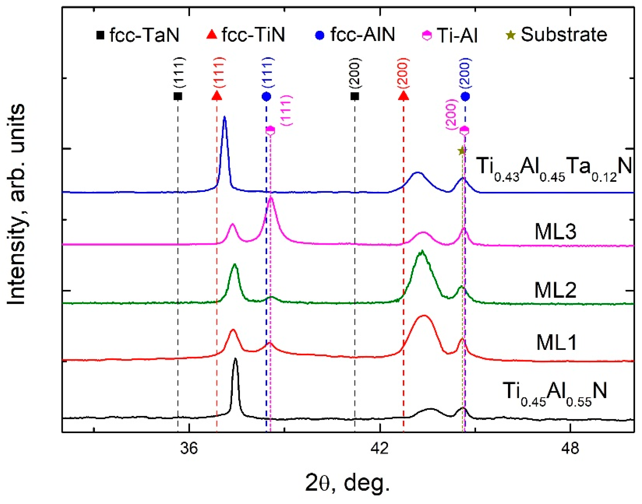
EDS analysis revealed that the Ti1−xAlxN monolithic coating as well as the Ti1−xAlxN layers in the multilayers were characterized by a Ti/Al ratio of 45/55 at %. The same Ti/Al ratio was also found in the Ti-Al layers. The Ta-alloyed coating was represented as Ti0.43Al0.45Ta0.12N. The X-ray diffraction patterns of the coatings are shown in Figure 1. An analysis of the XRD patterns showed that the Ti0.45Al0.55N and Ti0.43Al0.45Ta0.12N monolithic coatings are Ti1−x−yAlx(Tay)N solid solutions with single-phase cubic B1 (NaCl-type) structure. The XRD patterns of the Ti0.45Al0.55N/Ti0.45Al0.55 multilayer coatings also exhibit the diffraction peaks of the same phase. In addition, the peaks of the TiAl γ-phase with tetragonal L10 structure are seen in the XRD patterns of the multilayers. The strongest TiAl peak appears on the XRD pattern of the coating with the thickest metal layers (ML3). It is worth noting that the Ti1−x−yAlx(Tay)N diffraction peaks at the XRD pattern of the Ti0.43Al0.45Ta0.12N coating are shifted towards lower diffraction angles compared to other samples. This can be attributed to the higher residual stress in this coating as well as to the presence of the fcc-TaN phase, which lattice constant (0.434 nm) is larger than that of TiN. The XRD analysis also indicates the texture changes in the multilayer coatings compared with the monolithic ones. Crystallites in both monolithic coatings preferentially grow along (111) direction, while the multilayers exhibit (200) Ti1−xAlxN texture.

Figure 1.
XRD patterns of the Ti0.45Al0.55N and Ti0.43Al0.45Ta0.12N monolithic coatings, and Ti0.45Al0.55N/Ti0.45Al0.55 multilayers.
It has been shown that high residual stresses favor the formation of (111) texture in TiN [47] and Ti-Al-N coatings [48], while (200) crystallites preferentially grow at low residual stresses. Therefore, the (200) texture indicates partial relaxation of the residual stresses in the multilayer coatings due to the fact that the ductile metal layers allow the Ti0.45Al0.55N layers to fit their dimensions by sliding over each other. This is strongly supported by the results of residual stress evaluation by substrate curvature measurements. The Ti0.45Al0.55N and Ti0.43Al0.45Ta0.12N monolithic coatings are characterized by compressive stresses of −1.6 and −3.0 GPa, respectively, whereas the compressive stresses in the multilayers are reduced to ~−0.5 (see Table 1).
The hardness and reduced elastic modulus of the coatings determined by instrumented nanoindentation are presented in Table 1. It is seen that the multilayers and the Ti0.43Al0.45Ta0.12N coating are characterized by lower H and E* values compared with the Ti0.45Al0.55N coating. In the case of the multilayers, this effect is due to the contribution of the metal layers to the mechanical response of the coatings during nanoindentation, which grows with increasing their relative thickness. Therefore, the ML3 coating, with the thickness of the metal layers being equal to 60% of its total thickness, has the lowest H and E*. The softening of the Ti0.43Al0.45Ta0.12N coating can be attributed to the changes in the chemical bonding induced by Ta alloying. Density functional theory calculations have showed that the alloying increases occupancy of d-t2g metallic states, significantly reduces the ionicity of the Al-N bonds and leads to the formation of a layered electronic structure of Ti1−x−yAlxTayN solid solutions that facilitates their shear deformation and decreases their strength compared with Ti1−xAlxN, which is primarily characterized by ionic bonding [10,49]. It should be noted that the hardness of the ML1 and ML3 coatings decreases greater than the reduced elastic modulus that results in reducing their H/E* ratio, which is commonly used to rank toughness and ductility of hard coatings [50,51]. In contrast, the H/E* ratio of the ML2 and Ti0.43Al0.45Ta0.12N coatings increases compared with the Ti0.45Al0.55N one. The results show that the hardness-to-modulus ratio is inappropriate to compare the toughness of the monolithic and multilayer coatings, because the ML1 and ML3 coatings with large relative thicknesses of the metal layers obviously should be tougher than the Ti0.45Al0.55N coating. This discrepancy can be attributed to the fact that, in contrast to brittle materials, for which the chemical bond strength dominates the resistance to fracture, plastic flow and ductile tearing primarily determine the energy dissipated during fracture of ductile materials. However, this mechanical behavior cannot be properly characterized by the hardness-to-modulus ratio. The increase in the H/E* ratio of the ML2 coating is evidently associated with a quite large thickness of the hard Ti0.45Al0.55N layers. At the applied indentation depths, the measured hardness is mainly contributed by the mechanical response of the outmost ceramic layer, whereas the measured reduced elastic modulus is significantly contributed by the metal layers due to the long-range elastic strain fields. Finally, it should be noted that the H/E* ratio clearly indicates the enhanced toughness of the Ta-alloyed coating.
3.2. Scratch Testing
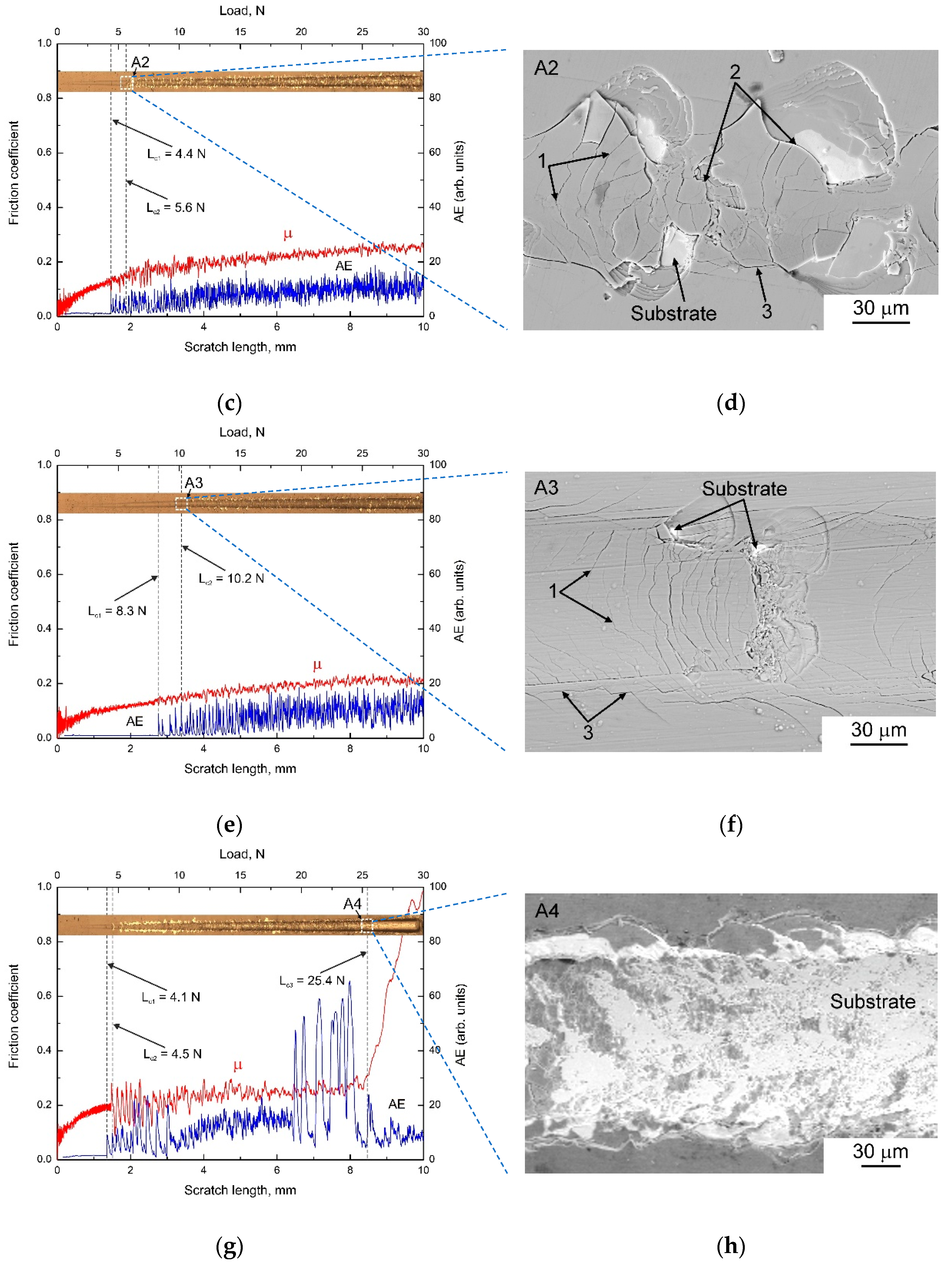
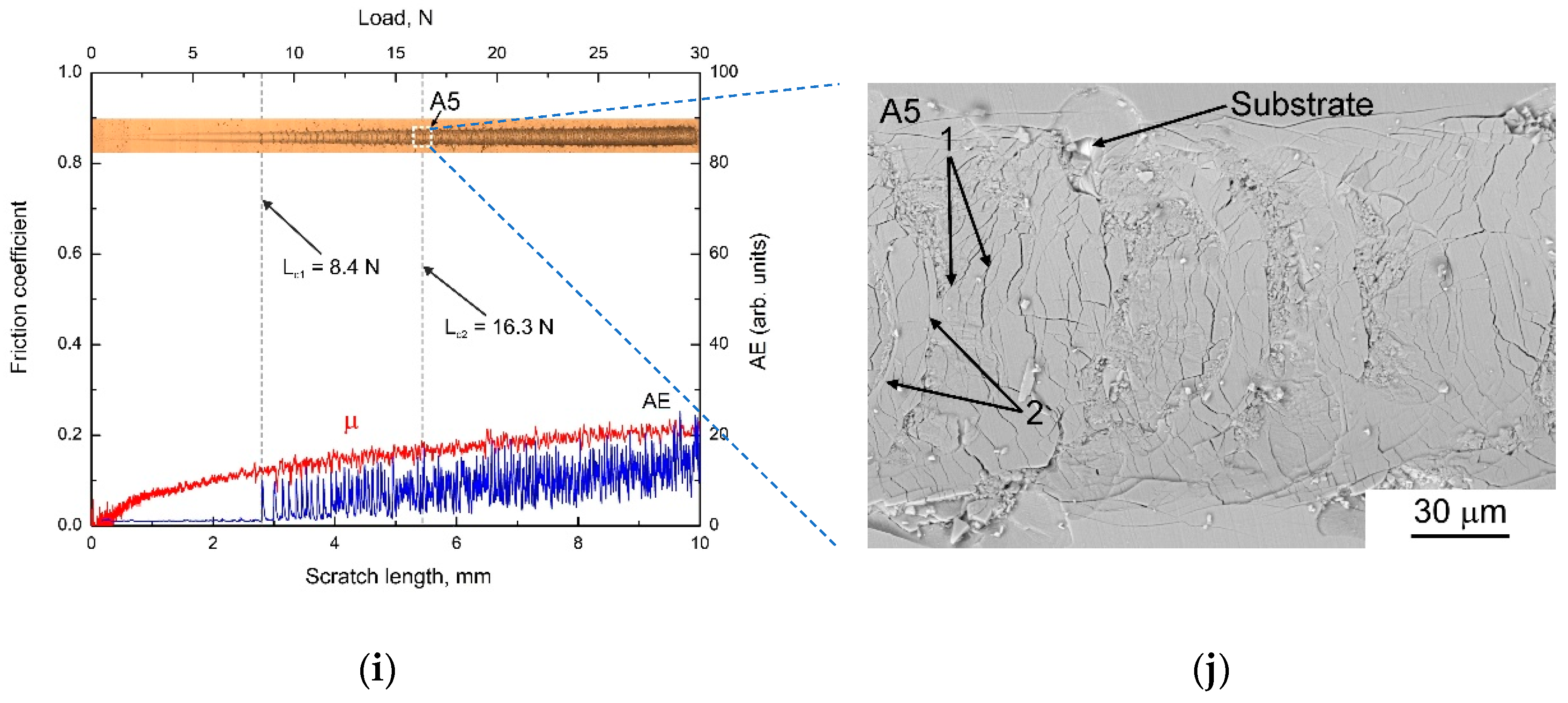
Figure 2 (left panel) shows the evolution of the friction coefficient and the acoustic emission signal during scratching of the coatings with a progressively increasing applied normal load. The corresponding optical micrographs of the scratches are shown above the curves. The right panel of Figure 2 exhibits the corresponding SEM micrographs of specific areas of the scratch tracks outlined by dashed lines and denoted as A1-A5. Due to the rather low hardness (~5 GPa) the steel substrate underwent plastic deformation already at the initial stage of scratching, which led to the formation of a residual scratch groove. The hard tip ploughed the substrate, i.e., displaced its material from the bottom of the scratch groove to the edges resulted in the formation of pile-ups at scratch flanks and ahead the tip. This was accompanied by coherent bending of the coatings, which induced the concentration of tensile stresses at the pile-up ridges. As a result, the coatings tend to crack in these areas. Microscopic examination of the scratch tracks revealed that the coating failure started from the emergence of parallel cracks along the edges of the grooves. However, the edge cracks were formed out of the contact area and did not generate significant acoustic emission output. In all the coatings the first sudden AE peak corresponding to the first critical load Lc1 was attributed to the nearly simultaneous appearance of semicircular backward tensile and forward conformal cracks inside the scratch tracks. These two failure modes are common for scratching of hard coatings on ductile substrates [52,53]. The tensile cracks are caused by the friction-induced tensile stresses behind the moving tip and tensile stresses resulting from coating bending at the rear of the contact area under the action of normal load. The conformal cracking is concerned with the formation of the pile-up ahead the tip, which results in transfer of a large amount of the applied load to the front half of the tip substantially enhancing the contact stress [52]. In addition, the tangential friction generates compressive stresses ahead the tip, which lead to increasing bending curvature of the coatings at the pile-up and therefore promote their buckling failure. The Ti0.45Al0.55N coating is characterized by the lowest critical load Lc1 = 3.5 N, whereas highest Lc1 values of 8.3 and 8.4 N correspond to the multilayer with the thickest Ti0.45Al0.55N layers (ML2) and the Ti0.43Al0.45Ta0.12N coating, respectively.
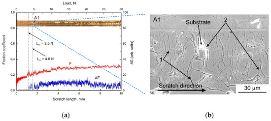
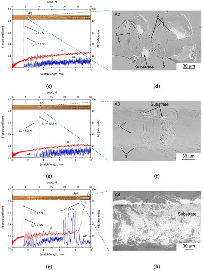

Figure 2.
Scratch tracks, friction coefficients (µ), acoustic emission signals (AE) and critical loads (left panel), and corresponding SEM micrographs of specific areas of the scratch tracks denoted as A1–A5 (right panel) of (a,b) Ti0.45Al0.55N; (c,d) ML1; (e,f) ML2; (g,h) ML3; and (i,j) Ti0.43Al0.45Ta0.12N coatings, respectively. Arrows in the right panel indicate different types of cracks: 1—tensile cracks; 2—conformal cracks; 3—edge cracks.
The formation of the conformal cracks ahead of the tip was followed by the tip passing over and pushing the piled-up material into the substrate. This resulted in the formation of new cracks and coating fragmentation inside the scratch tracks. Chipping of the coatings was also observed, which was especially pronounced close to the conformal cracks and in the areas of overlapping of the tensile, conformal and edge cracks. In the Ti0.45Al0.55N, ML1, and ML3 coatings this soon resulted in spallation of their fragments with partial substrate exposure (see, e.g., Figure 2b,d), which defined the second critical load Lc2 commonly used to rank coating adhesion. A lowest Lc2 value of 4.5 N was determined in the ML3 coating. Moreover, in contrast to the other samples, continuous spallation of this coating occurred at a critical load Lc3 of 25.4 N. This resulted in complete substrate exposure in the scratch groove (Figure 2h), which was accompanied by a sharp increase in the friction coefficient (see Figure 2g). The Ti0.45Al0.55N and ML1 coatings were not completely removed from the scratch groove despite the large areas of substrate exposure. The ML2 and Ti0.43Al0.45Ta0.12N coatings have exhibited substantially higher Lc2 loads, which are equal to 10.2 N and 16.3 N, respectively. These coatings are also characterized by significantly smaller areas of the substrate exposure compared with other samples (Figure 2f,g). This is especially true for the Ti0.43Al0.45Ta0.12N coating, which scratch track contains a few of small isolated areas of coating spallation.
The scratch testing of the coatings showed that the introduction of the ductile Ti0.45Al0.55 layers into the Ti0.45Al0.55N coating and alloying with Ta led to their significant toughening. As can be seen from Figure 2b, cracks easily propagate throughout the Ti0.45Al0.55N coating without deflection that leads to substrate exposure all over the chipping area. In contrast, the chipping of the multilayer and Ti0.43Al0.45Ta0.12N coatings is accompanied by deflection of the through-thickness cracks so that either the chipping does not result in the substrate exposure or the exposed area is substantially smaller than the total chipped area (Figure 2d,f,j). In the case of the multilayers, the crack deflection primarily occurs at the interfaces between the layers, because their toughening is only provided by the ductile metal layers. Crack propagation in ductile materials is accompanied by the development of a zone of plastic flow around the crack tip [54], therefore the Ti0.45Al0.55 layers result in a substantial increase in the amount of work dissipated during propagation of the through-thickness cracks. In contrast, in the Ti0.43Al0.45Ta0.12N coating the cracks are deflected throughout its thickness, since the toughening is attributed to the changes in the chemical bonding [10,28]. In addition, the Ti0.43Al0.45Ta0.12N coating is also characterized by the highest compressive residual stresses, which hinder crack nucleation and propagation [55]. Therefore, this coating demonstrated the strongest resistance to cracking and spallation among the samples studied. Despite the evident toughening, the ML1 and ML3 coatings exhibited poor scratch resistance. The ML3 performance was even worse than that of the Ti0.45Al0.55N coating. This can be attributed to poor load-bearing capacity of the ML1 and ML3 coatings due to their reduced hardness and elastic modulus. In the former case, the hard Ti0.45Al0.55N layers are too thin to prevent deformation of the underlying Ti0.45Al0.55 layers. In the latter case, the metal layers are too thick to provide a good support for the ceramic layers. Therefore, the tip deeper penetrates into these samples resulting in a larger amount of plastic deformation of the substrate and stronger bending of the coatings. The latter facilitates their cracking and spallation. Thus, the optimal multilayer architecture, which can provide benefits in mechanical performance under applying normal loads, should balance enhanced toughness with good load-bearing capacity. Evidently, only the ML2 coating, which is comprised of rather thick Ti0.45Al0.55N layers and thin Ti0.45Al0.55N layers, meets this requirement.
3.3. Uniaxial Tension
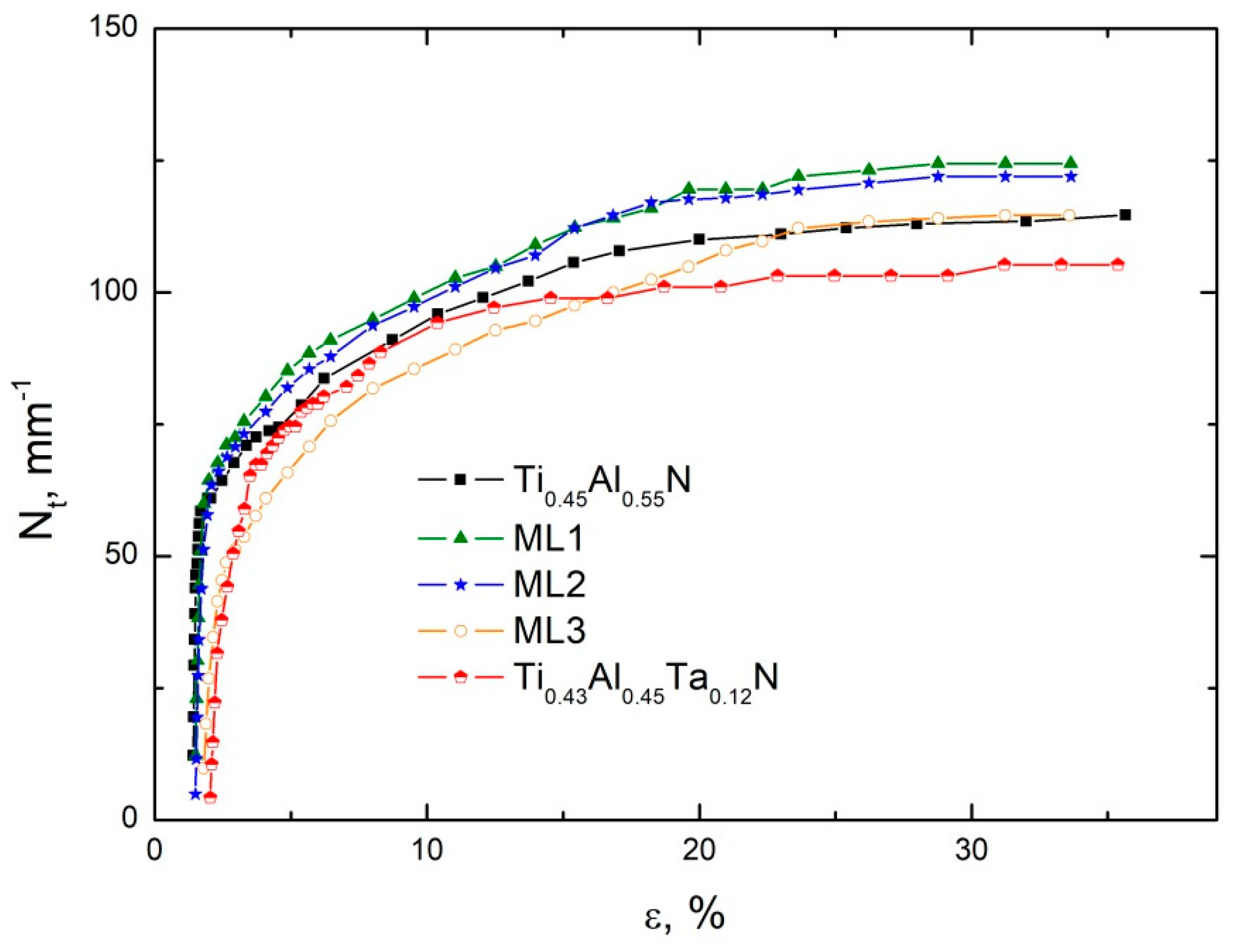
Four consecutive failure stages were revealed under uniaxial tension of all the samples studied. The critical strains corresponding to the onset of these stages (εI–εIV) are listed in Table 2. Stage I (primary cracking) began with sudden appearance of numerous cracks oriented perpendicular to the tensile axis (transverse cracks) (Figure 3a). It has been shown that such cracks provide relaxation of the tensile stress only near the free edges of the coating fragments, while the stress rapidly increases at a distance from the edges [56]. Therefore, stage I was characterized by sharply increasing crack density Nt (the number of cracks per unit length of the samples) with increasing substrate elongation (Figure 4). This resulted in the formation of a system of parallel cracks, which distribution was initially random, but became quasi-periodical to the end of stage I. The reason for this is that the tensile stress reaches its maximum value at the middle point of the coating fragments [56]. Therefore, the formation of new cracks becomes increasingly probable at this point. The Ti0.45Al0.55N, ML1, and ML2 coatings exhibited the similar crack multiplication rate at stage I. The crack multiplication rate was lower for the Ti0.43Al0.45Ta0.12N and ML3 coatings, but the duration of stage I increased, especially in the case of the ML3 coating. As a result, the Ti0.45Al0.55N, ML1, ML2, and Ti0.43Al0.45Ta0.12N coatings were characterized by close Nt values (61–65 mm−1) to the end of stage I, while the crack density in the ML3 coating was 49 mm−1.
Table 2.
Substrate elongations corresponding to the onset of different failure stages of the coatings and the relative area of coating spallation after fracture of the substrates.
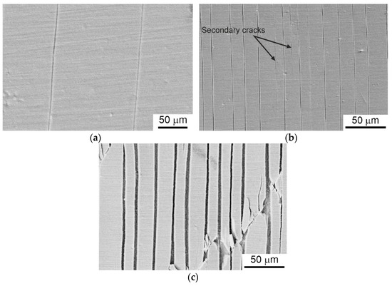
Figure 3.
Different failure stages of the Ti0.45Al0.55N coating: a—primary cracking (stage I); b—secondary cracking (stage II); c—diagonal cracking (stage III). The SEM micrographs correspond to (a) 1.4%; (b) 2.0%; and (c) 5.0% substrate elongation.
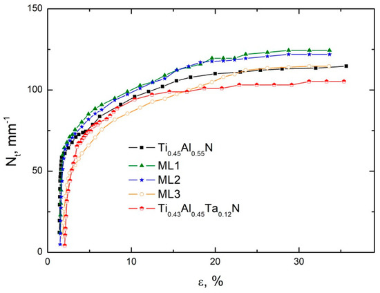
Figure 4.
Density of transverse cracks in the coatings subjected to uniaxial tension as a function of substrate elongation.
Because of the above-mentioned stress distribution in the coating fragments, at stage II (secondary cracking) new transverse cracks primarily initiated in the middle between the existing cracks (Figure 3b). This failure stage was characterized by the reduced crack multiplication rate (which was similar for all the coatings), since the greater strain increment was needed to exceed the coating tensile strength with decreasing the dimensions of its fragments.
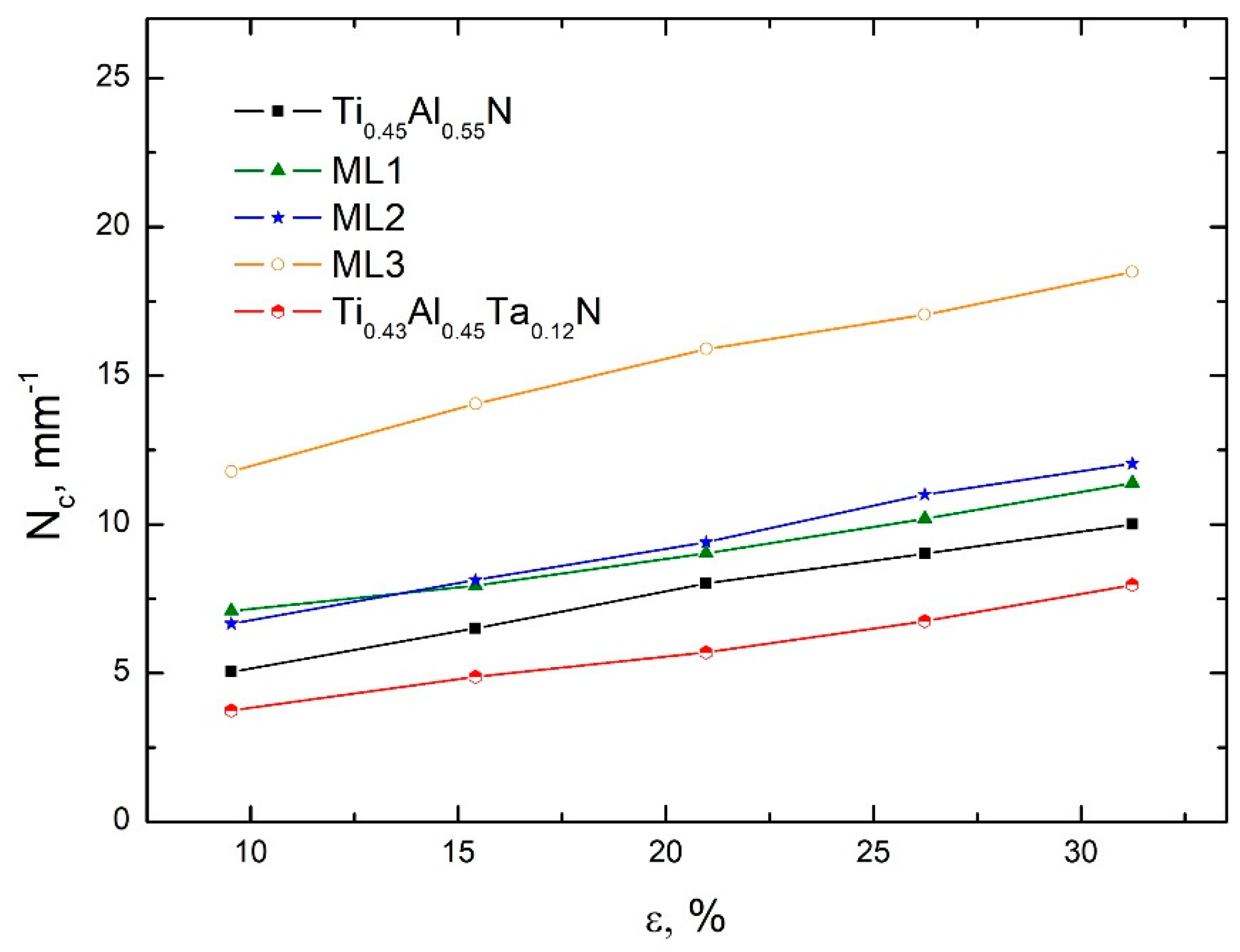
Stage III of the coating failure was characterized by the formation of diagonal cracks propagated at an angle of 50–65° to the tensile loading (Figure 3c). The formation of these cracks can be attributed to (i) the shear deformation of the steel substrate [57], which is confirmed by the observed shift of coating fragments along the diagonal cracks and their rotation; and (ii) the Poisson’s contraction and necking of the substrate, which cannot be accommodated by the brittle coatings [42,58]. Due to the rigid bonding between the coating and substrate, the latter effects generate the lateral compressive stresses in the coatings. Superposition of these compressive stresses and the tensile stresses along the loading axis promotes the formation of the diagonal cracks. Figure 5 shows that the density of the diagonal cracks demonstrates virtually linear growth until the substrate fracture. In contrast, the multiplication of the transverse cracks at stage III slowed down significantly, since the diagonal cracks provided partial relaxation of the tensile stress.
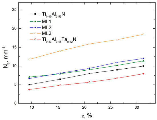
Figure 5.
Density of diagonal cracks in the coatings subjected to uniaxial tension as a function of substrate elongation.
The last stage of the coating failure (stage IV) started with beginning delamination and spallation of coating fragments and continued to the fracture of the substrates. All the multilayers started to delaminate at larger strains than the Ti0.45Al0.55N and Ti0.43Al0.45Ta0.12N coatings (see Table 2). Average values of the relative spallation area (S) of the coatings after the fracture of the substrates are given in Table 2. It is seen that the most pronounced spallation happened in the Ti0.45Al0.55N coating, while the ML3 coating was characterized by the least spallation area. This is also visible in Figure 6, which exhibits plan-view SEM micrographs of the samples after tension to fracture of the substrates obtained in the backscattered electron mode. The areas of the exposed Ti substrates have bright contrast in these micrographs, while the fragments of the Ti0.45Al0.55N and multilayer coatings have dark contrast because they are rich with light elements such as aluminum and nitrogen. Only the Ti0.43Al0.45Ta0.12N coating has similar contrast with the substrate due to the presence of Ta. It should be noted that the spallation predominantly occurred near the diagonal cracks and at their intersections (Figure 6), where it was stimulated by contact interaction of coating fragments due to their displacements relative each other caused by shears in the substrates. The multiplication of the transverse cracks virtually ceased at stage IV because the coating delamination provided stress relaxation.

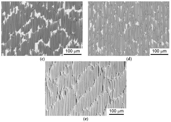
Figure 6.
SEM micrographs of the (a) Ti0.45Al0.55N; (b) ML1; (c) ML2; (d) ML3 and (e) Ti0.43Al0.45Ta0.12N after uniaxial tension to fracture of the substrates.
The evolution of the cracking patterns in the coatings subjected to uniaxial tension depends on a number of parameters. The main of them are the tensile strength, stiffness, fracture toughness, and residual stress of the coatings as well as the interfacial shear strength of the coating/substrate system. The higher tensile strength results in the higher tensile strain, which the coating can withstand before cracking. This implies the later onset of the cracking and the lower crack density, because the stresses under uniaxial tension are transferred from the substrate to the coating and each its fragment is loaded independently. The stiffer coatings are characterized by larger tensile stresses at the same strain, which lead to earlier cracking and increased crack density. The improved toughness hinders crack initiation and propagation reducing the crack density. The compressive residual stress in the coatings gives rise to higher ultimate tensile strain and lower cracking density, since in this case the effective stress that induces the coating fracture is the sum of the negative residual stress and the positive tensile stress. The tensile residual stress has the opposite effect. Finally, the higher interfacial strength results in the higher crack density, because the coating fracture under tension is governed by the competition between the edge delamination of coating fragments and their cracking [56,59].
The interplay between the above-mentioned factors determines the cracking behavior of the coatings studied. The higher toughness and lower stiffness of the ML1 and ML2 multilayers hinder their cracking and are responsible for the shift of the onset of I and II failure stages towards higher strains compared with the Ti0.45Al0.55N coating. However, the lower compressive residual stresses and stronger adhesion to the substrates, which is evidenced by the smaller spallation areas, lead to somewhat higher resultant crack density in these coatings. Even higher toughness and lesser stiffness of the ML3 coating due to the presence of the thick ductile Ti0.45Al0.55 interlayers provide even later onset of I and II failure stages and decreases the resultant crack density to that of Ti0.45Al0.55N. Finally, the Ti0.43Al0.45Ta0.12N coating is characterized by the combination of the enhanced toughness, reduced stiffness and highest compressive residual stress. This leads to the highest critical strains εI and εII and the lowest resultant cracking density among the samples studied. Thus, the Ta-alloyed coating exhibited the best crack resistance under uniaxial tension. However, it should be noted that in some applications—e.g., under exposure to extreme environments—the most important parameter can be the area of coating spallation rather than the cracking density. This is due to the crack healing phenomena—e.g., by means of chemical reactions with atmospheric oxygen at high temperatures—which results in filling the cracks and prolonging the coating durability [60,61,62]. In contrast, the spallation can potentially remove the entire coating resulting in rapid degradation of the underlying substrate [63,64]. Therefore, the ML3 coating can be the most promising for such applications because it is characterized by the enhanced spallation resistance compared with the other coatings, which can be attributed to the largest relative thickness of the metal layers in this coating. This results in its significantly lower elastic modulus, and therefore the reduced tensile stresses under loading, decreasing the energy release rate for coating delamination [34]. In addition, the ML3 coating is obviously characterized by the lower shear strength that leads to the highest density of the diagonal cracks among the coatings studied. These cracks provide relaxation of both the tensile and compressive stresses in the coating fragments, hindering their delamination.
4. Conclusions
The comparative study revealed the effect of the multilayer architecture and Ta alloying on the mechanical behavior of Ti1−xAlxN coatings on steel substrates subjected to scratch testing and uniaxial tension. It was found that, in contrast to the Ti0.45Al0.55N coating, cracks nucleated in the Ti0.43Al0.45Ta0.12N coating during scratching deflected throughout its thickness. The toughening of the Ta-alloyed coating in combination with retained hardness provided the strong resistance to cracking and spallation under scratch testing. Despite the evident toughening, the Ti0.45Al0.55N/Ti0.45Al0.55 multilayers exhibited the poorer performance under the contact loading compared with the Ta-alloyed coating. This is caused by the deteriorated load-bearing capacity of the multilayer coatings, containing rather soft and compliant metal layers, which furthers large out-of-plane deformation of the coating/substrate system, and consequently coating cracking and delamination. The results indicate that the optimal multilayer architecture, which can provide benefits in mechanical performance of the coatings under applying normal loads, should balance enhanced toughness with good load-bearing capacity. Therefore, the most promising was the multilayer coating consisting of thick ceramic and thin metal layers, which was characterized by significantly smaller areas of the substrate exposure compared with other multilayers. The Ti0.43Al0.45Ta0.12N coating also exhibited the best crack resistance under in-plane tensile straining. However, it started to delaminate from the substrate at a lower strain than the multilayer coatings and was characterized by a higher relative spallation area than the multilayer with the thickest metal layers. Since, under exposure to extreme environments, the area of coating spallation is a more important parameter than the cracking density, the multilayer coatings with thick metal layers can be promising for preventing rapid degradation of the underlying substrate under in-plane strain conditions.
Author Contributions
Conceptualization, A.R.S.; methodology, A.R.S.; investigation, E.D.K. and A.R.S.; writing—original draft preparation, A.R.S.; visualization, E.D.K.; supervision, A.R.S. Both authors have read and agreed to the published version of the manuscript.
Funding
The work was performed according to the Government research assignment for ISPMS SB RAS, project no. FWRW-2021-0010.
Institutional Review Board Statement
Not applicable.
Informed Consent Statement
Not applicable.
Data Availability Statement
The data presented in this study are available on request from the corresponding author.
Conflicts of Interest
The authors declare no conflict of interest.
References
- Mayrhofer, P.H.; Rachbauer, R.; Holec, D.; Rovere, F.; Schneider, J.M. Protective transition metal nitride coatings. In Comprehensive Materials Processing; Elsevier: Amsterdam, The Netherlands, 2014; Volume 4, pp. 355–388. [Google Scholar] [CrossRef]
- PalDey, S.; Deevi, S.C. Single layer and multilayer wear resistant coatings of (Ti,Al)N: A review. Mater. Sci. Eng. A 2003, 342, 58–79. [Google Scholar] [CrossRef]
- Chen, L.; Paulitsch, J.; Du, Y.; Mayrhofer, P.H. Thermal stability and oxidation resistance of Ti-Al-N coatings. Surf. Coat. Technol. 2012, 206, 2954–2960. [Google Scholar] [CrossRef] [Green Version]
- Shulepov, I.A.; Kashkarov, E.B.; Stepanov, I.B.; Syrtanov, M.S.; Sutygina, A.N.; Shanenkov, I.; Obrosov, A.; Weiß, S. The formation of composite Ti-Al-N coatings using filtered vacuum arc deposition with separate cathodes. Metals 2017, 7, 497. [Google Scholar] [CrossRef] [Green Version]
- Sousa, V.F.C.; da Silva, F.J.G.; Pinto, G.F.; Baptista, A.; Alexandre, R. Characteristics and wear mechanisms of TiAlN-based coatings for machining applications: A comprehensive review. Metals 2021, 11, 260. [Google Scholar] [CrossRef]
- Tillmann, W.; Grisales, D.; Stangier, D.; Butzke, T. Tribomechanical behaviour of TiAlN and CrAlN coatings deposited onto AISI H11 with different pre-treatments. Coatings 2019, 9, 519. [Google Scholar] [CrossRef] [Green Version]
- Oliveira, V.M.C.A.; Vazquez, A.M.; Aguiar, C.; Robin, A.; Barboza, M.J.R. Nitride coatings improve Ti-6Al-4V alloy behavior in creep tests. Mater. Sci. Eng. A 2016, 670, 357–368. [Google Scholar] [CrossRef]
- Mikula, M.; Plašienka, D.; Sangiovanni, D.G.; Sahul, M.; Roch, T.; Truchlý, M.; Gregor, M.; Čaplovič, L.; Plecenik, A.; Kúš, P. Toughness enhancement in highly NbN-alloyed Ti-Al-N hard coatings. Acta Mater. 2016, 121, 59–67. [Google Scholar] [CrossRef]
- Chen, Y.H.; Roa, J.J.; Yu, C.H.; Johansson-Jõesaar, M.P.; Andersson, J.M.; Anglada, M.J.; Odén, M.; Rogström, L. Enhanced thermal stability and fracture toughness of TiAlN coatings by Cr, Nb and V-alloying. Surf. Coat. Technol. 2018, 342, 85–93. [Google Scholar] [CrossRef]
- Eremeev, S.V.; Shugurov, A.R. Chemical bonding analysis in Ti1−x−yAlxTayN solid solutions. Surf. Coat. Technol. 2020, 395, 125803. [Google Scholar] [CrossRef]
- Guo, T.; Qiao, L.; Pang, X.; Volinsky, A.A. Brittle film-induced cracking of ductile substrates. Acta Mater. 2015, 99, 273–280. [Google Scholar] [CrossRef]
- Guo, T.; Chen, Y.; Cao, R.; Pang, X.; He, J.; Qiao, L. Cleavage cracking of ductile-metal substrates induced by brittle coating fracture. Acta Mater. 2018, 152, 77–85. [Google Scholar] [CrossRef]
- Ritchie, R.O. The Conflicts between strength and toughness. Nat. Mater. 2011, 10, 817–822. [Google Scholar] [CrossRef]
- Li, G.; Li, L.; Han, M.; Luo, S.; Jin, J.; Wang, L.; Gu, J.; Miao, H. The performance of TiAlSiN coated cemented carbide tools enhanced by inserting Ti interlayers. Metals 2019, 9, 918. [Google Scholar] [CrossRef] [Green Version]
- Zhang, M.; Zhou, F.; Wang, Q.; Fu, Y.; Zhou, Z. Structural and tribological properties of CrMoCN coatings with various Mo contents in artificial seawater. Appl. Surf. Sci. 2019, 493, 485–496. [Google Scholar] [CrossRef]
- Holleck, H.; Schier, V. Multilayer PVD coatings for wear protection. Surf. Coat. Technol. 1995, 76–77, 328–336. [Google Scholar] [CrossRef]
- Zhang, S.; Sun, D.; Fu, Y.; Du, H. Toughening of hard nanostructural thin films: A critical review. Surf. Coat. Technol. 2005, 198, 2–8. [Google Scholar] [CrossRef]
- Wang, Y.X.; Zhang, S. Toward hard yet tough ceramic coatings. Surf. Coat. Technol. 2014, 258, 1–16. [Google Scholar] [CrossRef]
- Vieira, M.T.; Ramos, A.S. Influence of ductile interlayers on the mechanical performance of tungsten nitride coatings. J. Mater. Process. Technol. 1999, 92–93, 156–161. [Google Scholar] [CrossRef] [Green Version]
- Castanho, J.M.; Vieira, M.T. Effect of ductile layers in mechanical behaviour of TiAlN thin coatings. Proc. J. Mater. Process. Technol. 2003, 143–144, 352–357. [Google Scholar] [CrossRef] [Green Version]
- Vogli, E.; Tillmann, W.; Selvadurai-Lassl, U.; Fischer, G.; Herper, J. Influence of Ti/TiAlN-multilayer designs on their residual stresses and mechanical properties. Appl. Surf. Sci. 2011, 257, 8550–8557. [Google Scholar] [CrossRef]
- Du, H.; Zhao, H.; Xiong, J.; Xian, G. Effect of interlayers on the structure and properties of TiAlN based coatings on WC-Co cemented carbide substrate. Int. J. Refract. Met. Hard Mater. 2013, 37, 60–66. [Google Scholar] [CrossRef]
- Shang, H.; Li, J.; Shao, T. Mechanical properties and thermal stability of TiAlN/Ta multilayer film deposited by ion beam assisted deposition. Appl. Surf. Sci. 2014, 310, 317–320. [Google Scholar] [CrossRef]
- Shuai, J.; Zuo, X.; Wang, Z.; Guo, P.; Xu, B.; Zhou, J.; Wang, A.; Ke, P. Comparative study on crack resistance of TiAlN monolithic and Ti/TiAlN multilayer coatings. Ceram. Int. 2020, 46, 6672–6681. [Google Scholar] [CrossRef]
- Glatz, S.A.; Hollerweger, R.; Polcik, P.; Rachbauer, R.; Paulitsch, J.; Mayrhofer, P.H. Thermal stability and mechanical properties of arc evaporated Ti-Al-Zr-N hard coatings. Surf. Coat. Technol. 2015, 266, 1–9. [Google Scholar] [CrossRef]
- Glatz, S.A.; Koller, C.M.; Bolvardi, H.; Kolozsvári, S.; Riedl, H.; Mayrhofer, P.H. Influence of Mo on the structure and the tribomechanical properties of arc evaporated Ti-Al-N. Surf. Coat. Technol. 2017, 311, 330–336. [Google Scholar] [CrossRef]
- Glatz, S.A.; Bolvardi, H.; Kolozsvári, S.; Koller, C.M.; Riedl, H.; Mayrhofer, P.H. Arc evaporated W-alloyed Ti-Al-N coatings for improved thermal stability, mechanical, and tribological properties. Surf. Coat. Technol. 2017, 332, 275–282. [Google Scholar] [CrossRef]
- Mikula, M.; Truchlý, M.; Sangiovanni, D.G.; Plašienka, D.; Roch, T.; Gregor, M.; Ďurina, P.; Janík, M.; Kúš, P. Experimental and computational studies on toughness enhancement in Ti-Al-Ta-N quaternaries. J. Vac. Sci. Technol. A Vac. Surf. Film. 2017, 35, 060602. [Google Scholar] [CrossRef]
- Aninat, R.; Valle, N.; Chemin, J.B.; Duday, D.; Michotte, C.; Penoy, M.; Bourgeois, L.; Choquet, P. Addition of Ta and Y in a hard Ti-Al-N PVD coating: Individual and conjugated effect on the oxidation and wear properties. Corros. Sci. 2019, 156, 171–180. [Google Scholar] [CrossRef]
- Guo, F.; Holec, D.; Wang, J.; Li, S.; Du, Y. Impact of V, Hf and Si on oxidation processes in Ti–Al–N: Insights from ab-initio molecular dynamics. Surf. Coat. Technol. 2020, 381, 125125. [Google Scholar] [CrossRef]
- Kot, M.; Rakowski, W.; Major, Ł.; Lackner, J. Load-bearing capacity of coating-substrate systems obtained from spherical indentation tests. Mater. Des. 2013, 46, 751–757. [Google Scholar] [CrossRef]
- Hutchinson, J.W.; Suo, Z. Mixed mode cracking in layered materials. Adv. Appl. Mech. 1991, 29, 63–191. [Google Scholar] [CrossRef]
- Cotterell, B.; Chen, Z. Buckling and cracking of thin films on compliant substrates under compression. Int. J. Fract. 2000, 104, 169–179. [Google Scholar] [CrossRef]
- Balint, D.S.; Hutchinson, J.W. Mode II edge delamination of compressed thin films. J. Appl. Mech. Trans. ASME 2001, 68, 725–730. [Google Scholar] [CrossRef]
- Alaca, B.E.; Saif, M.T.A.; Sehitoglu, H. On the interface debond at the edge of a thin film on a thick substrate. Acta Mater. 2002, 50, 1197–1209. [Google Scholar] [CrossRef]
- Pac, M.J.; Pinot, Y.; Giljean, S.; Rousselot, C.; Delobelle, P.; Ulhaq-Bouillet, C.; Tuilier, M.H. Investigation of Ti0.54Al0.46/Ti0.54Al0.46N multilayer films deposited by reactive gas pulsing process by nano-indentation and electron energy-loss spectroscopy. Thin Solid Film. 2017, 634, 96–106. [Google Scholar] [CrossRef]
- Colombo, D.A.; Mandri, A.D.; Echeverría, M.D.; Massone, J.M.; Dommarco, R.C. Mechanical and tribological behavior of Ti/TiN and TiAl/TiAlN coated austempered ductile iron. Thin Solid Film. 2018, 647, 19–25. [Google Scholar] [CrossRef] [Green Version]
- Seidl, W.M.; Bartosik, M.; Kolozsvári, S.; Bolvardi, H.; Mayrhofer, P.H. Influence of Ta on the fracture toughness of arc evaporated Ti-Al-N. Vacuum 2018, 150, 24–28. [Google Scholar] [CrossRef]
- Shugurov, A.R.; Kuzminov, E.D.; Kasterov, A.M.; Panin, A.V.; Dmitriev, A.I. Tuning of mechanical properties of Ti1−xAlxN coatings through Ta alloying. Surf. Coat. Technol. 2020, 382, 125219. [Google Scholar] [CrossRef]
- Zhang, S.; Sun, D.; Fu, Y.; Du, H. Toughness measurement of thin films: A critical review. Surf. Coat. Technol. 2005, 198, 74–84. [Google Scholar] [CrossRef]
- Shugurov, A.R.; Akulinkin, A.A.; Panin, A.V.; Sergeev, V.P.; Kalashnikov, M.P.; Voronov, A.V.; Cheng, C.H. Study of crack resistance of TiAlN coatings by scratch testing. Phys. Mesomech. 2017, 20, 185–192. [Google Scholar] [CrossRef]
- Chen, B.F.; Hwang, J.; Yu, G.P.; Huang, J.H. In-situ observation of the cracking behavior of TiN coating on 304 stainless steel subjected to tensile strain. Thin Solid Film. 1999, 352, 173–178. [Google Scholar] [CrossRef]
- Panin, A.V.; Shugurov, A.R.; Kazachenok, M.S.; Sergeev, V.P. Effect of the nanostructuring of a Cu substrate on the fracture of heat-resistant Si-Al-N coatings during uniaxial tension. Tech. Phys. 2012, 57, 779–786. [Google Scholar] [CrossRef]
- Shugurov, A.R.; Panin, A.V.; Dmitriev, A.I.; Nikonov, A.Y. Multiscale fracture of Ti-Al-N coatings under uniaxial tension. Phys. Mesomech. 2021, 24, 185–195. [Google Scholar] [CrossRef]
- Oliver, W.; Pharr, G. An improved technique for determining hardness and elastic modulus using load and displacement sensing indentation experiments. J. Mater. Res. 1992, 7, 1564–1583. [Google Scholar] [CrossRef]
- Stoney, G.G. The tension of metallic films deposited by electrolysis. Proc. R. Soc. A 1909, 82, 172–175. [Google Scholar] [CrossRef] [Green Version]
- Pelleg, J.; Zevin, L.Z.; Lungo, S.; Croitoru, N. Reactive-sputter-deposited TiN films on glass substrates. Thin Solid Film. 1991, 197, 117–128. [Google Scholar] [CrossRef]
- Ahlgren, M.; Blomqvist, H. Influence of bias variation on residual stress and texture in TiAlN PVD coatings. Surf. Coat. Technol. 2005, 200, 157–160. [Google Scholar] [CrossRef]
- Sangiovanni, D.G.; Chirita, V.; Hultman, L. Toughness enhancement in TiAlN-based quarternary alloys. Thin Solid Film. 2012, 520, 4080–4088. [Google Scholar] [CrossRef] [Green Version]
- Leyland, A.; Matthews, A. On the significance of the H/E ratio in wear control: A nanocomposite coating approach to optimised tribological behavior. Wear 2000, 246, 1–11. [Google Scholar] [CrossRef]
- Musil, J. Hard nanocomposite coatings: Thermal stability, oxidation resistance and toughness. Surf. Coat. Technol. 2012, 207, 50–65. [Google Scholar] [CrossRef]
- Bull, S.J. Failure Modes in scratch adhesion testing. Surf. Coat. Technol. 1991, 50, 25–32. [Google Scholar] [CrossRef]
- Bull, S.J. Failure mode maps in the thin film scratch adhesion test. Tribol. Int. 1997, 30, 491–498. [Google Scholar] [CrossRef]
- Besel, M.; Breitbarth, E. Advanced analysis of crack tip plastic zone under cyclic loading. Int. J. Fatigue 2016, 93, 92–108. [Google Scholar] [CrossRef]
- Massl, S.; Thomma, W.; Keckes, J.; Pippan, R. Investigation of fracture properties of magnetron-sputtered TiN films by means of a FIB-based cantilever bending technique. Acta Mater. 2009, 57, 1768–1776. [Google Scholar] [CrossRef]
- Xie, C.; Tong, W. Cracking and decohesion of a thin Al2O3 film on a ductile Al-5%Mg substrate. Acta Mater. 2005, 53, 477–485. [Google Scholar] [CrossRef]
- Choi, H.W.; Lee, K.-R.; Wang, R.; Oh, K.H. Fracture behavior of diamond-like carbon films on stainless steel under a micro-tensile test condition. Diam. Relat. Mater. 2006, 15, 38–43. [Google Scholar] [CrossRef]
- Ohmura, T.; Matsuoka, S. Evaluation of mechanical properties of ceramic coatings on a metal substrate. Surf. Coat. Technol. 2003, 169–170, 728–731. [Google Scholar] [CrossRef]
- Agrawal, D.C.; Raj, R. Ultimate shear strengths of copper-silica and nickel-silica interfaces. Mater. Sci. Eng. A 1990, 126, 125–131. [Google Scholar] [CrossRef]
- Lee, S.K.; Ishida, W.; Lee, S.Y.; Nam, K.W.; Ando, K. Crack-healing behavior and resultant strength properties of silicon carbide ceramic. J. Eur. Ceram. Soc. 2005, 25, 569–576. [Google Scholar] [CrossRef]
- Tavangarian, F.; Hui, D.; Li, G. Crack-healing in ceramics. Compos. Part B Eng. 2018, 144, 56–87. [Google Scholar] [CrossRef]
- Seo, H.-I.; Kim, D.; Lee, K.S. Crack healing in mullite-based EBC during thermal shock cycle. Coatings 2019, 9, 585. [Google Scholar] [CrossRef] [Green Version]
- Summers, W.D.; Begley, M.R.; Zok, F.W. Transition from penetration cracking to spallation in environmental barrier coatings on ceramic composites. Surf. Coat. Technol. 2019, 378, 125083. [Google Scholar] [CrossRef]
- Darolia, R. Thermal barrier coatings technology: Critical review, progress update, remaining challenges and prospects. Int. Mater. Rev. 2013, 58, 315–348. [Google Scholar] [CrossRef]


Publisher’s Note: MDPI stays neutral with regard to jurisdictional claims in published maps and institutional affiliations. |
© 2021 by the authors. Licensee MDPI, Basel, Switzerland. This article is an open access article distributed under the terms and conditions of the Creative Commons Attribution (CC BY) license (https://creativecommons.org/licenses/by/4.0/).