
Additive Manufacturing of Bulk Metallic Glasses—Process, Challenges and Properties: A Review


Abstract
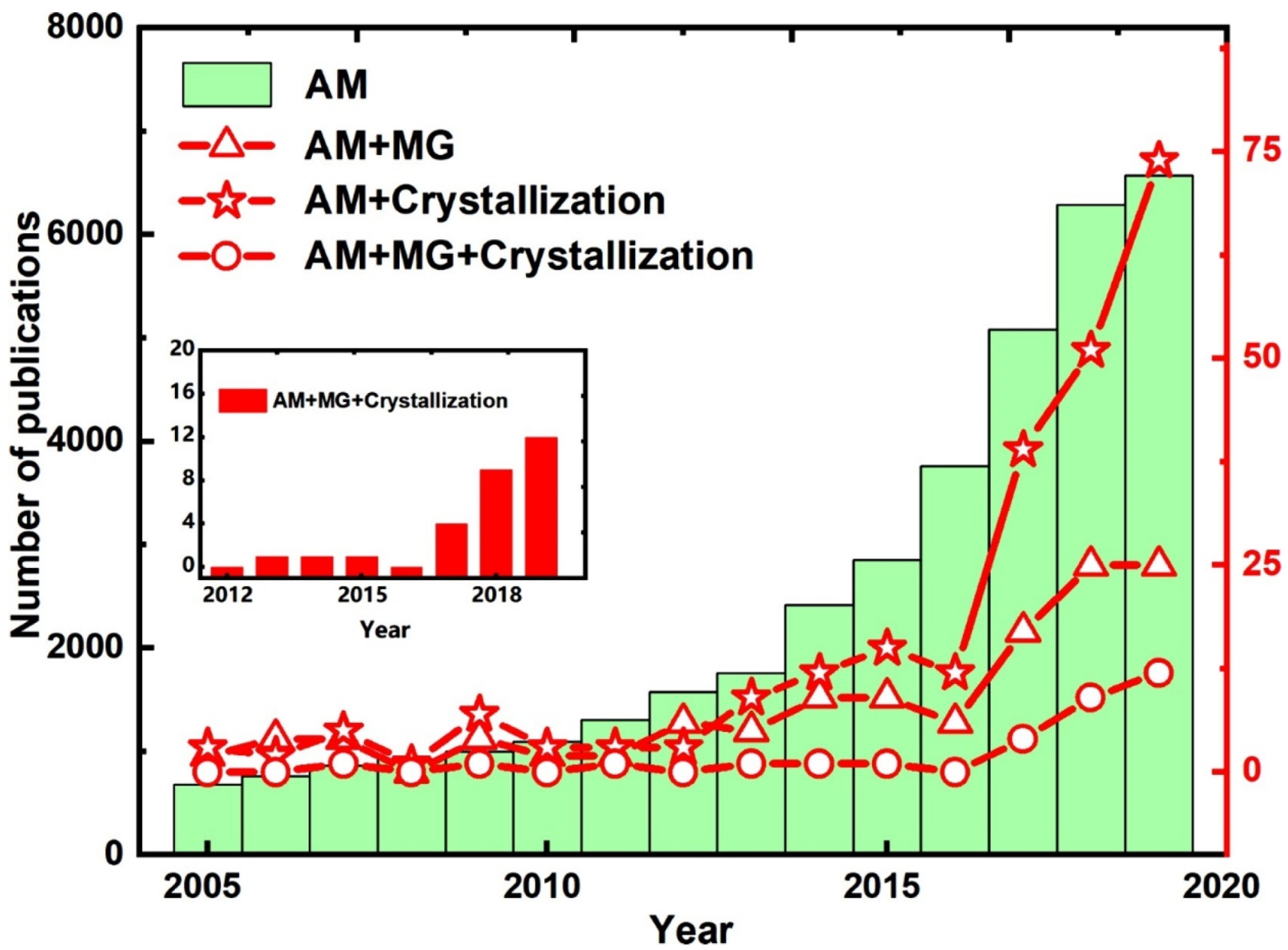
1. Introduction
- The materials used in AM of BMGs.
- Challenges in AM of BMGs, such as optimization of processing parameters, defects formation, residual stresses, and low ductility of fabricated parts.
- Crystallization is the main challenge of AM of BMGs, which up to now no comprehensive explanation is presented for the different reasons for the crystallization of BMGs fabricated via AM techniques.
- Mechanical properties of BMGs fabricated via AM processes.
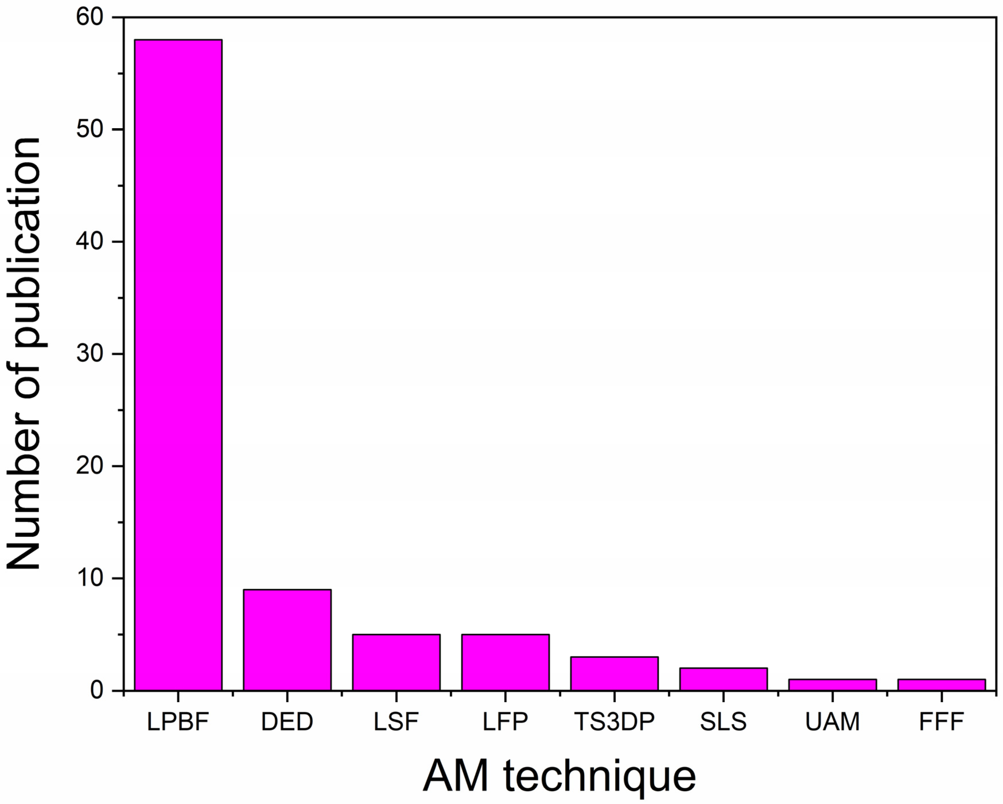
2. AM Techniques Used for Fabrication of BMGs
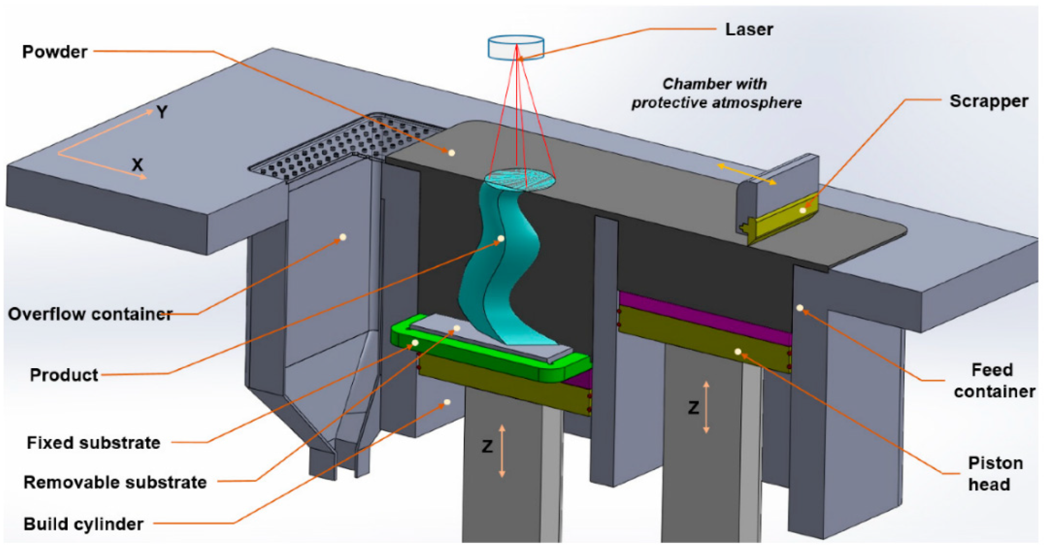
2.1. Powder-Bed Laser Methods
2.1.1. Laser Powder-Bed Fusion (LPBF)
2.1.2. Selective Laser Sintering (SLS)
2.1.3. Laser Solid Forming (LSF)
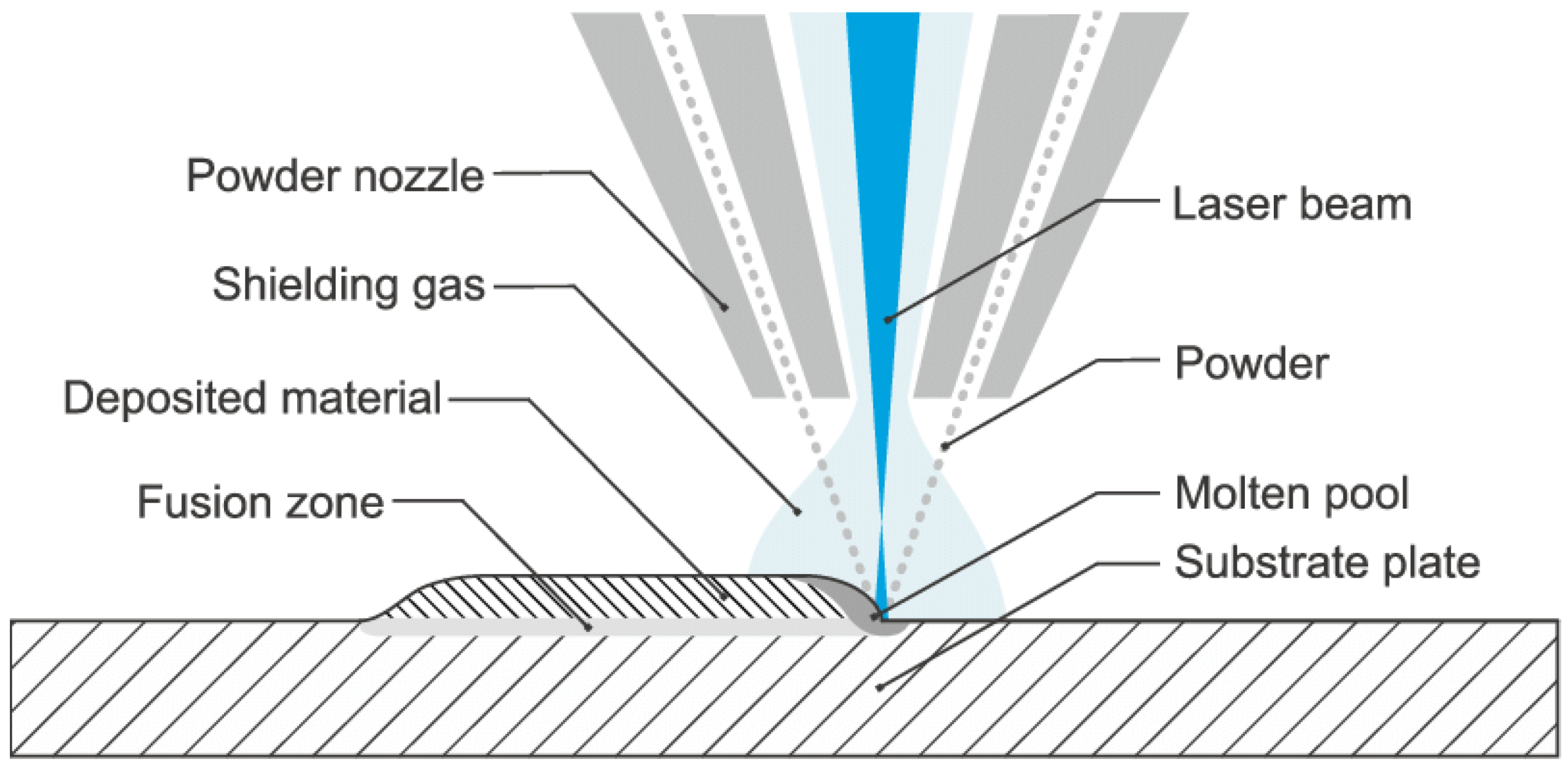
2.2. Direct Energy Deposition (DED)
2.3. Laser Foil Printing (LFP)
2.4. Thermal Spray 3D Printing (TS3DP)
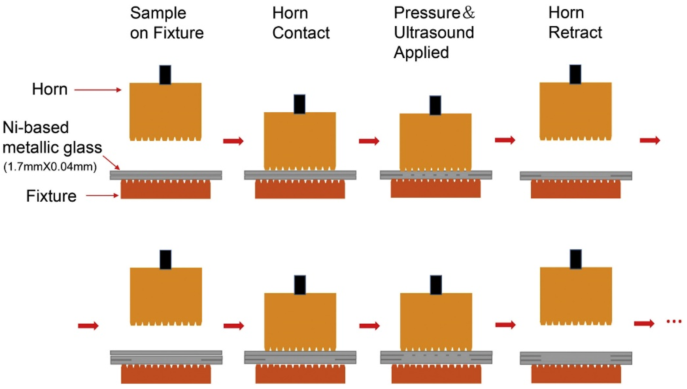
2.5. Ultrasonic Additive Manufacturing (UAM)
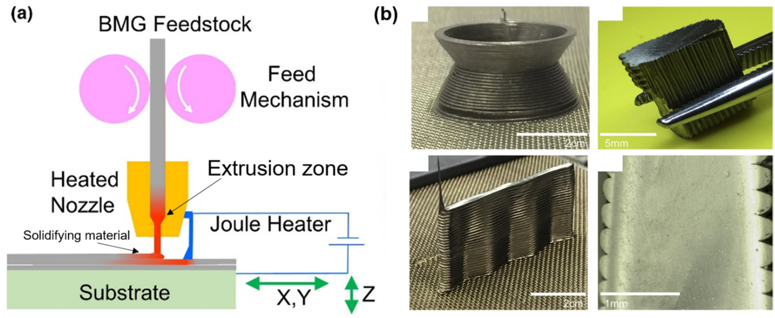
2.6. Fused Filament Fabrication (FFF)
3. Materials Used in AM of BMGs
3.1. Based on Zirconium
3.2. Based on Iron
3.3. Based on Aluminum
3.4. Based on Copper
3.5. Based on Nickel
3.6. Based on Titanium
3.7. Based on Precious Metals
4. Challenges
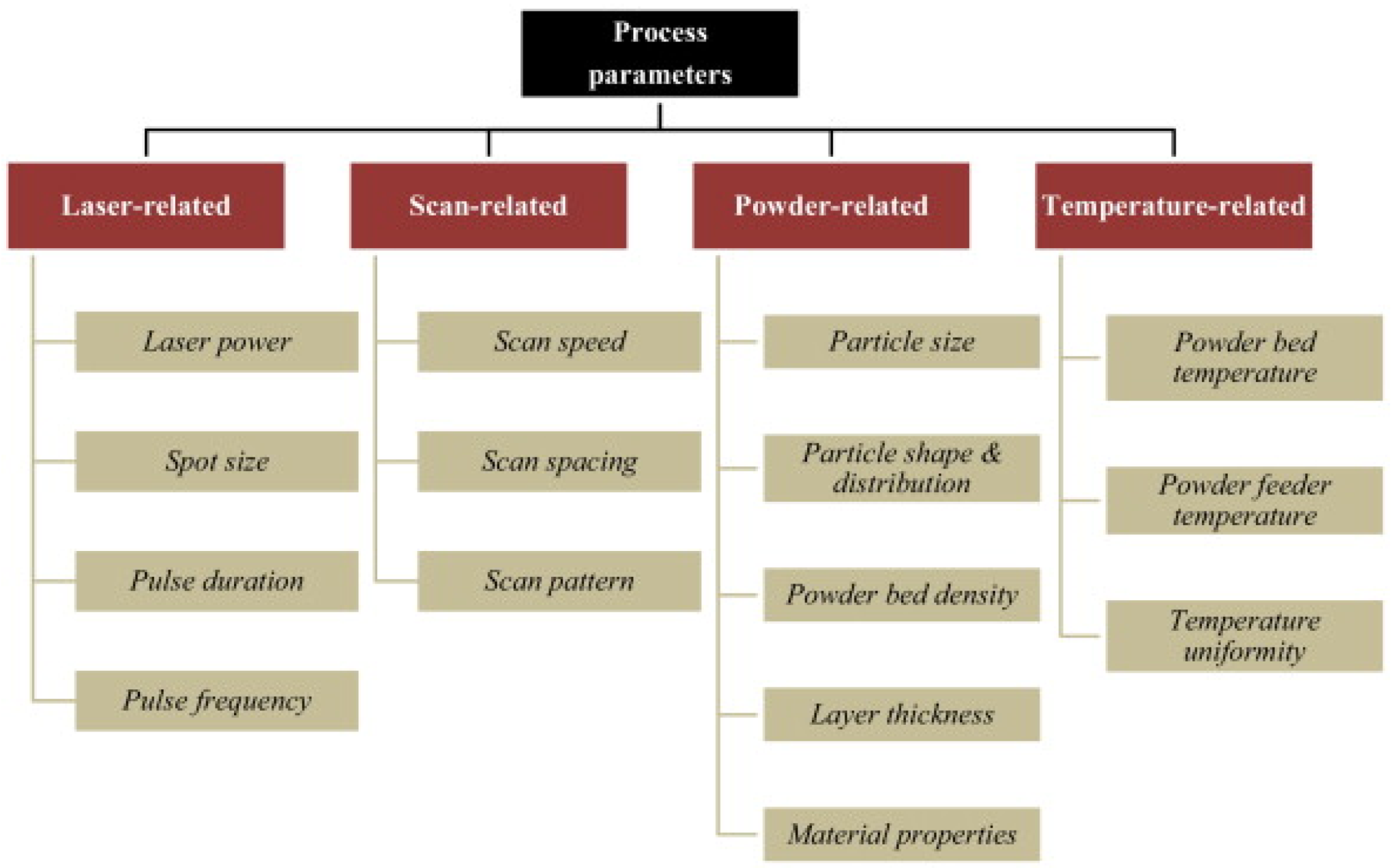
4.1. Parameter Optimization
4.2. Defects
4.2.1. Porosity
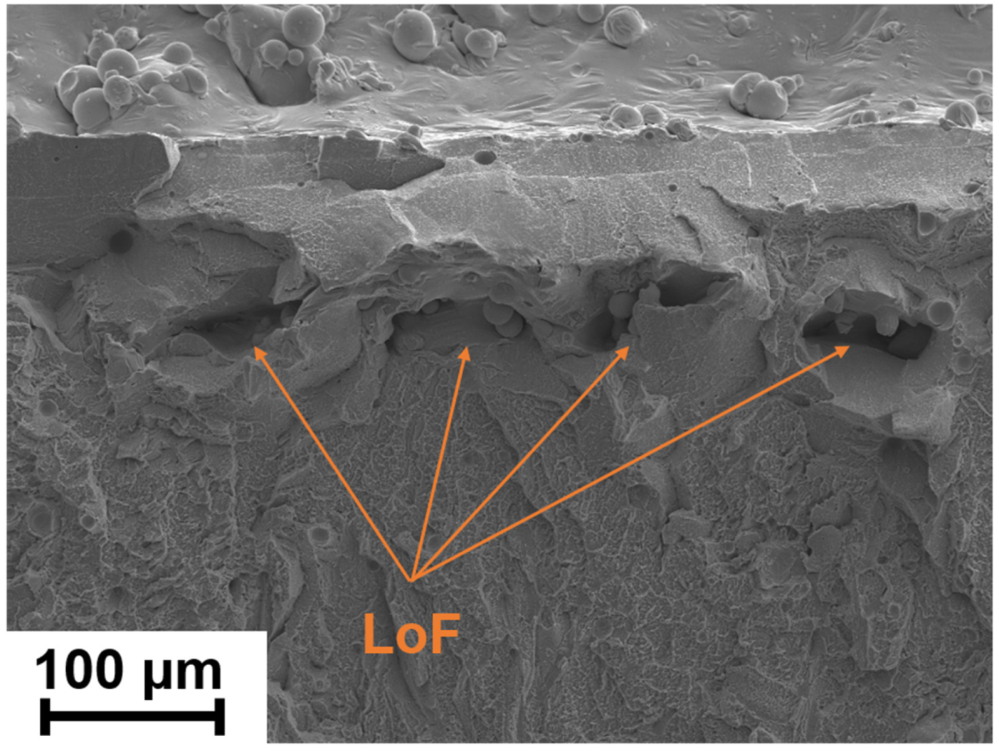
4.2.2. Lack of Fusion (LoF)
4.2.3. Crack
4.3. Residual Stress
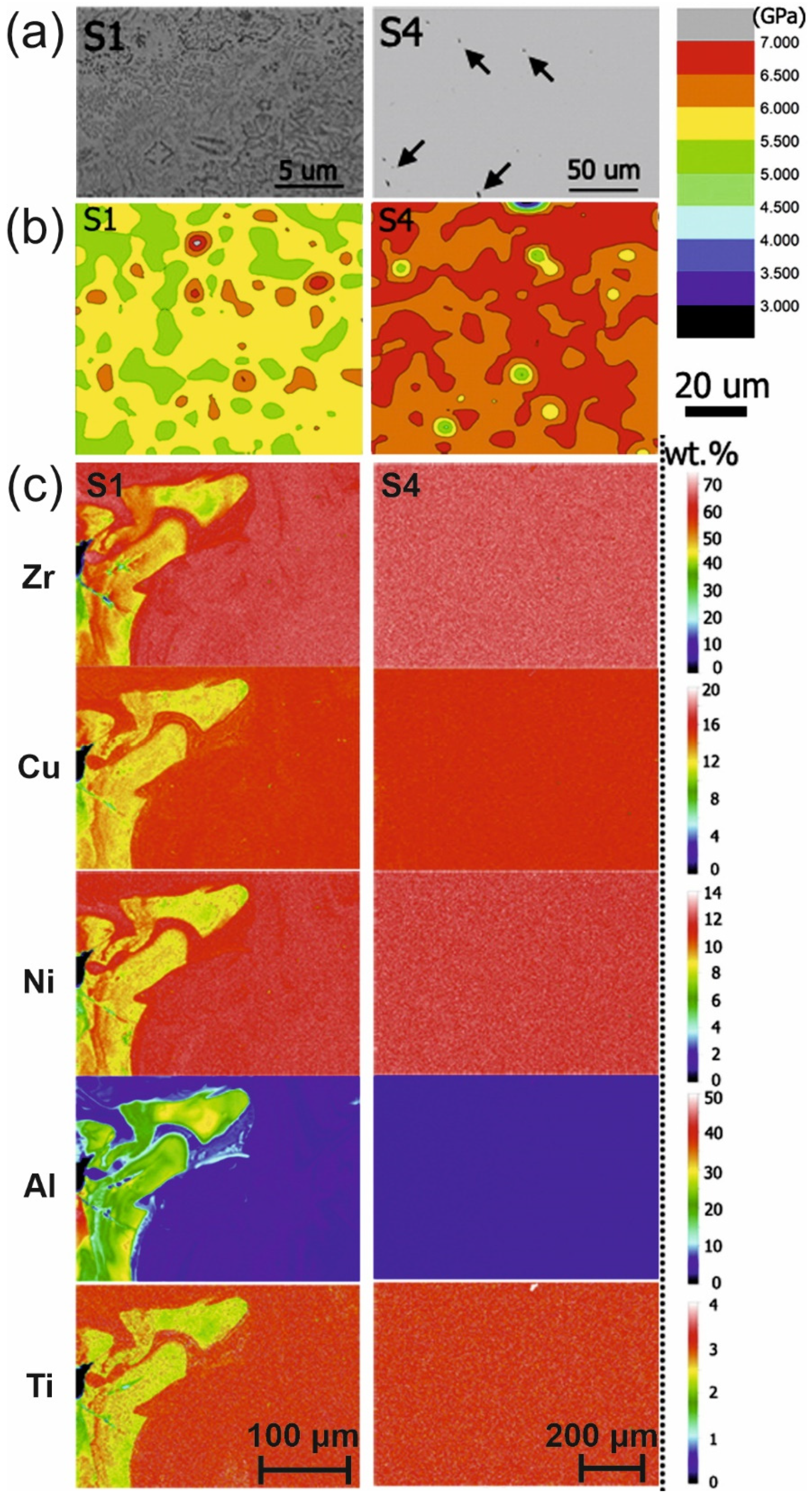
4.4. Homogeneity of the Structure
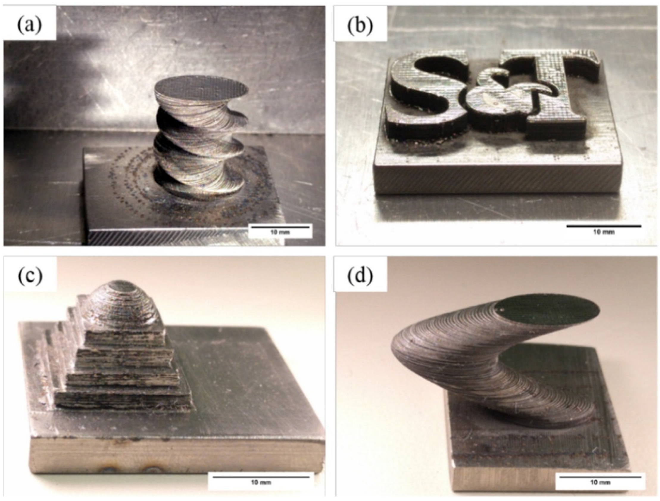
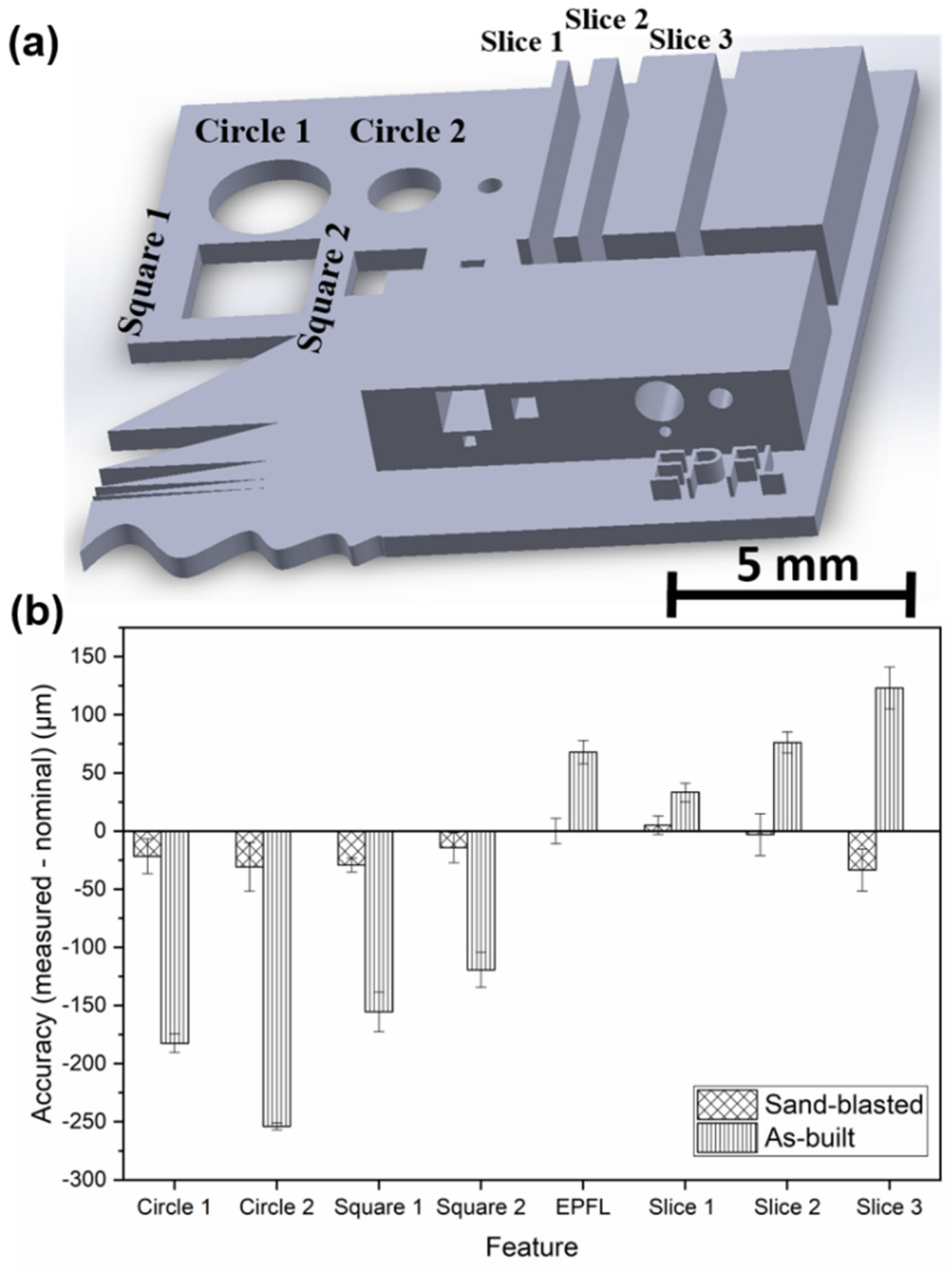
4.5. Complex Shapes
4.6. Crystallization of BMGs
4.6.1. Change in the Chemical Composition
4.6.2. Structural Relaxation
4.6.3. Time Spent at Temperatures Higher Than Tx
4.6.4. Shape Effect
4.6.5. Controlled Crystallization and Composite Formation
4.6.6. Global Heating
4.6.7. GFA Effect
4.6.8. Prediction of Crystallization
5. Mechanical Properties
5.1. Hardness
5.1.1. Microhardness
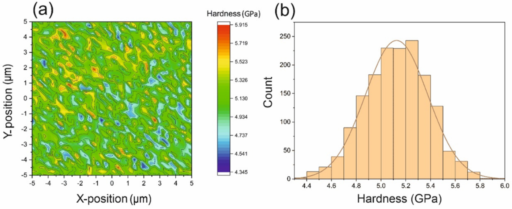
5.1.2. Nanohardness
5.2. Compressive Behavior
5.3. Tensile Behavior
5.4. Bending Behavior
5.5. Low Ductility
5.6. Fracture and Impact Toughness
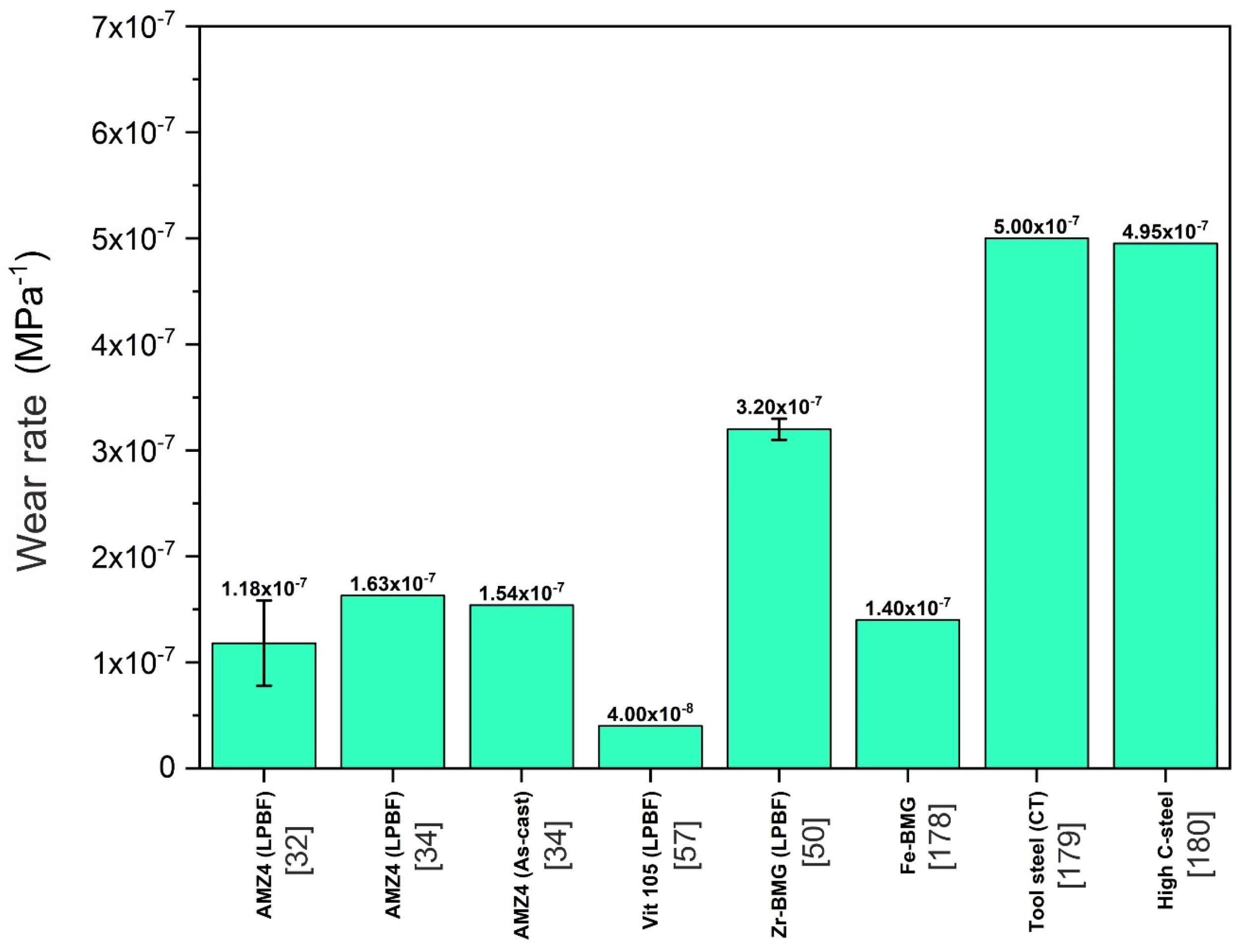
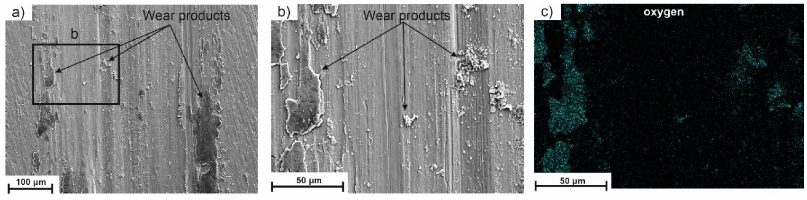
5.7. Wear Resistance
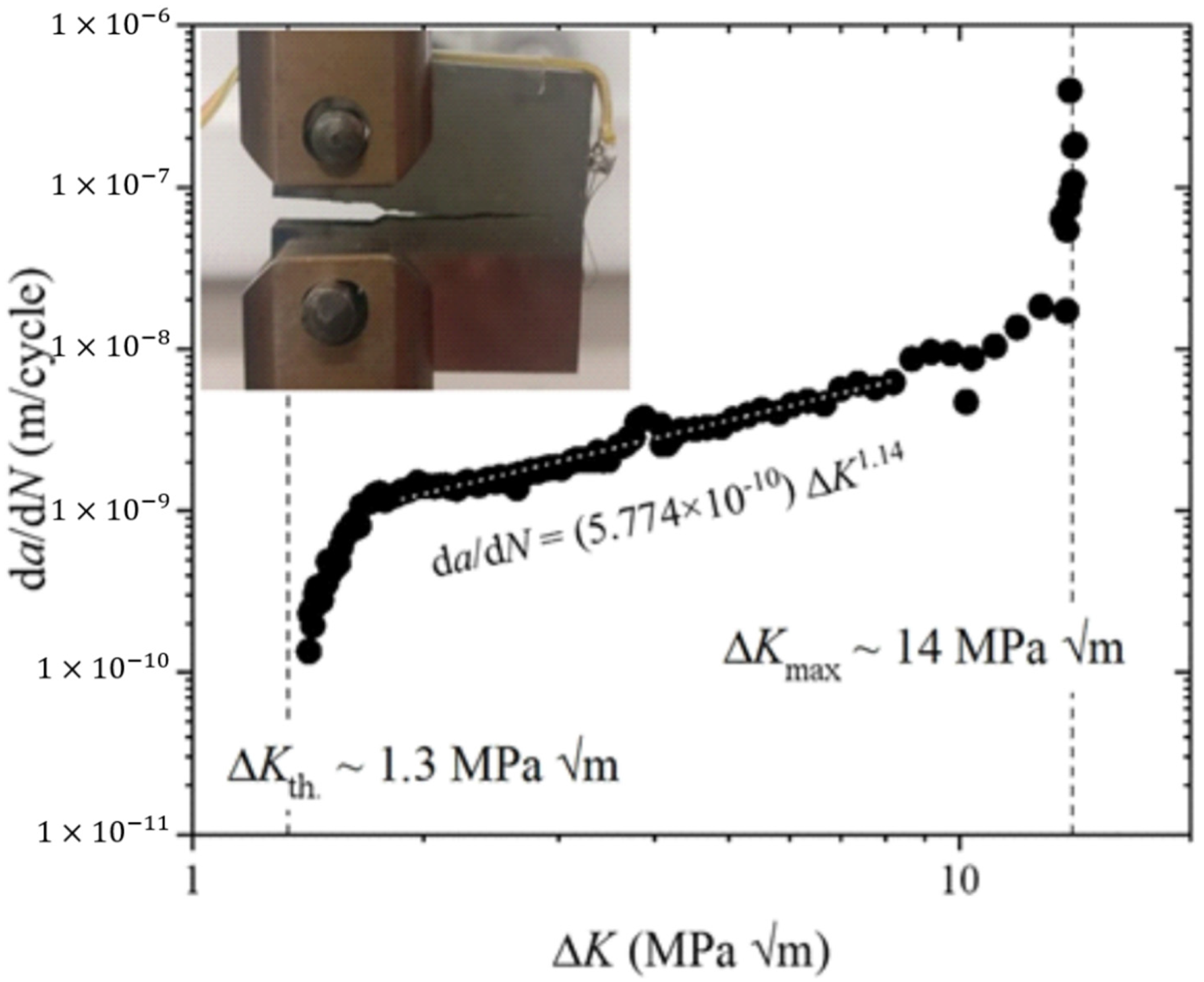
5.8. Fatigue Performance
6. Outlook
7. Summary
Author Contributions
Funding
Institutional Review Board Statement
Informed Consent Statement
Data Availability Statement
Acknowledgments
Conflicts of Interest
References
- Löffler, J.F.; Kündig, A.A.; Torre, F.H.D. Rapid Solidification and Bulk Metallic Glasses—Processing and Properties. In Materials Processing Handbook; Taylor & Francis Group: New York, NY, USA, 2007. [Google Scholar]
- Surynarayana, C.; Inoue, A. Bulk Metallic Glasses, 2nd ed.; Taylor& Francis Group: New York, NY, USA, 2018. [Google Scholar]
- Schroers, J. Processing of Bulk Metallic Glass. Adv. Mater. 2009, 22, 1566–1597. [Google Scholar] [CrossRef] [PubMed]
- Cardinal, S.; Pelletier, J.; Eisenbart, M.; Klotz, U. Influence of crystallinity on thermo-process ability and mechanical properties in a Au-based bulk metallic glass. Mater. Sci. Eng. A 2016, 660, 158–165. [Google Scholar] [CrossRef]
- Sohrabi, N.; Panikar, R.S.; Jhabvala, J.; Buch, A.R.; Mischler, S.; Logé, R.E. Laser coating of a Zr-based metallic glass on an aluminum substrate. Surf. Coat. Technol. 2020, 400, 126223. [Google Scholar] [CrossRef]
- Schroers, J.; Pham, Q.; Desai, A. Thermoplastic Forming of Bulk Metallic Glass—A Technology for MEMS and Microstructure Fabrication. J. Microelectromech. Syst. 2007, 16, 240–247. [Google Scholar] [CrossRef]
- Johnson, W.L.; Kaltenboeck, G.; Demetriou, M.D.; Schramm, J.P.; Liu, X.; Samwer, K.; Kim, C.P.; Hofmann, D.C. Beating Crystallization in Glass-Forming Metals by Millisecond Heating and Processing. Science 2011, 332, 828–833. [Google Scholar] [CrossRef]
- Ma, J.; Huang, Z.; Zheng, H.; Gong, F.; Liang, X. Controllable thermoplastic forming of bulk metallic glasses in milliseconds by resistance welding forming. Mater. Res. Express 2019, 6, 075210. [Google Scholar] [CrossRef]
- Allia, P.; Tiberto, P.M.; Baricco, M.; Vinai, F. Dc Joule heating of amorphous metallic ribbons: Experimental aspects and model. Rev. Sci. Instrum. 1993, 64, 1053. [Google Scholar] [CrossRef]
- Ma, J.; Liang, X.; Wu, X.; Liu, Z.; Gong, F. Sub-second thermoplastic forming of bulk metallic glasses by ultrasonic beating. Sci. Rep. 2015, 5, 17844. [Google Scholar] [CrossRef] [PubMed]
- Schroers, J. The superplastic forming of bulk metallic glasses. JOM 2005, 57, 35–39. [Google Scholar] [CrossRef]
- Duan, G.; Wiest, A.; Lind, M.L.; Li, J.; Rhim, W.-K.; Johnson, W.L. Bulk Metallic Glass with Benchmark Thermoplastic Processability. Adv. Mater. 2007, 19, 4272–4275. [Google Scholar] [CrossRef]
- Saotome, Y.; Iwazaki, H. Superplastic backward microextrusion of microparts for micro-electro-mechanical systems. J. Mater. Process. Technol. 2001, 119, 307–311. [Google Scholar] [CrossRef]
- Li, N.; Li, D.; Liu, L. Correlation between flow characteristics and interfacial friction behaviour of a Zr-based metallic glass during micro-extrusion. Philos. Mag. 2013, 93, 1859–1872. [Google Scholar] [CrossRef]
- Chevalier, A. Thermoplastic Forming and Deformation-Induced Crystallization of Bulk Metallic Glasses; EPFL: La Chaux-de-Fonds, Switzerland, 2019. [Google Scholar]
- Martinez, R.; Kumar, G.; Schroers, J. Hot rolling of bulk metallic glass in its supercooled liquid region. Scr. Mater. 2008, 59, 187–190. [Google Scholar] [CrossRef]
- Frazier, W.E. Metal Additive Manufacturing: A Review. J. Mater. Eng. Perform. 2014, 23, 1917–1928. [Google Scholar] [CrossRef]
- Liu, H.; Jiang, Q.; Huo, J.; Zhang, Y.; Yang, W.; Li, X. Crystallization in additive manufacturing of metallic glasses: A review. Addit. Manuf. 2020, 36, 101568. [Google Scholar] [CrossRef]
- Williams, E.; Lavery, N.P. Laser processing of bulk metallic glass: A review. J. Mater. Process. Technol. 2017, 247, 73–91. [Google Scholar] [CrossRef]
- Vilaro, T.; Kottman-Rexerodt, V.; Thomas, M.; Colin, C.; Bertrand, P.; Thivillon, L.; Abed, S.; Ji, V.; Aubry, P.; Peyre, P.; et al. Direct Fabrication of a Ti-47Al-2Cr-2Nb Alloy by Selective Laser Melting and Direct Metal Deposition Processes. Adv. Mater. Res. 2010, 89–91, 586–591. [Google Scholar] [CrossRef]
- Zheng, B.; Zhou, Y.; Smugeresky, J.E.; Lavernia, E.J. Processing and Behavior of Fe-Based Metallic Glass Components via Laser-Engineered Net Shaping. Met. Mater. Trans. A 2009, 40, 1235–1245. [Google Scholar] [CrossRef]
- Katakam, S.; Hwang, J.Y.; Paital, S.; Banerjee, R.; Vora, H.; Dahotre, N.B. In Situ Laser Synthesis of Fe-Based Amorphous Matrix Composite Coating on Structural Steel. Met. Mater. Trans. A 2012, 43, 4957–4966. [Google Scholar] [CrossRef]
- Gu, D.; Meiners, W.; Wissenbach, K.; Poprawe, R. Laser additive manufacturing of metallic components: Materials, processes and mechanisms. Int. Mater. Rev. 2012, 57, 133–164. [Google Scholar] [CrossRef]
- Li, X. Additive Manufacturing of Advanced Multi-Component Alloys: Bulk Metallic Glasses and High Entropy Alloys. Adv. Eng. Mater. 2018, 20, 1700874. [Google Scholar] [CrossRef]
- Ozden, M.G.; Morley, N.A. Laser Additive Manufacturing of Fe-Based Magnetic Amorphous Alloys. Magnetochemistry 2021, 7, 20. [Google Scholar] [CrossRef]
- Halim, Q.; Mohamed, N.A.N.; Rejab, M.R.M.; Naim, W.N.W.A.; Ma, Q. Metallic glass properties, processing method and development perspective: A review. Int. J. Adv. Manuf. Technol. 2021, 112, 1231–1258. [Google Scholar] [CrossRef]
- Zhang, C.; Ouyang, D.; Pauly, S.; Liu, L. 3D printing of bulk metallic glasses. Mater. Sci. Eng. R Rep. 2021, 145, 100625. [Google Scholar] [CrossRef]
- Bordeenithikasem, P.; Shen, Y.; Tsai, H.-L.; Hofmann, D.C. Enhanced mechanical properties of additively manufactured bulk metallic glasses produced through laser foil printing from continuous sheetmetal feedstock. Addit. Manuf. 2018, 19, 95–103. [Google Scholar] [CrossRef]
- Milewski, J.O. Additive Manufacturing of Metals; Springer International Publishing: Santa Fe, NM, USA, 2017. [Google Scholar]
- Debroy, T.; Wei, H.L.; Zuback, J.S.; Mukherjee, T.; Elmer, J.W.; Milewski, J.O.; Beese, A.M.; Wilson-Heid, A.D.; De, A.; Zhang, W. Additive manufacturing of metallic components–Process, structure and properties. Prog. Mater. Sci. 2018, 92, 112–224. [Google Scholar] [CrossRef]
- Park, H.S.; Nguyen, D.-S. Study on Flaking Behavior in Selective Laser Melting Process. Procedia CIRP 2017, 63, 569–572. [Google Scholar] [CrossRef]
- Sohrabi, N.; Jhabvala, J.; Kurtuldu, G.; Stoica, M.; Parrilli, A.; Berns, S.; Polatidis, E.; Van Petegem, S.; Hugon, S.; Neels, A.; et al. Characterization, mechanical properties and dimensional accuracy of a Zr-based bulk metallic glass manufactured via laser powder-bed fusion. Mater. Des. 2021, 199, 109400. [Google Scholar] [CrossRef]
- Pauly, S.; Schricker, C.; Scudino, S.; Deng, L.; Kühn, U. Processing a glass-forming Zr-based alloy by selective laser melting. Mater. Des. 2017, 135, 133–141. [Google Scholar] [CrossRef]
- Bordeenithikasem, P.; Stolpe, M.; Elsen, A.; Hofmann, D.C. Glass forming ability, flexural strength, and wear properties of additively manufactured Zr-based bulk metallic glasses produced through laser powder bed fusion. Addit. Manuf. 2018, 21, 312–317. [Google Scholar] [CrossRef]
- Ouyang, D.; Xing, W.; Li, N.; Li, Y.; Liu, L. Structural evolutions in 3D-printed Fe-based metallic glass fabricated by selective laser melting. Addit. Manuf. 2018, 23, 246–252. [Google Scholar] [CrossRef]
- Yang, C.; Zhang, C.; Xing, W.; Liu, L. 3D printing of Zr-based bulk metallic glasses with complex geometries and enhanced catalytic properties. Intermetallics 2018, 94, 22–28. [Google Scholar] [CrossRef]
- Mahbooba, Z.; Thorsson, L.; Unosson, M.; Skoglund, P.; West, H.; Horn, T.; Rock, C.; Vogli, E.; Harrysson, O. Additive manufacturing of an iron-based bulk metallic glass larger than the critical casting thickness. Appl. Mater. Today 2018, 11, 264–269. [Google Scholar] [CrossRef]
- Li, N.; Zhang, J.; Xing, W.; Ouyang, D.; Liu, L. 3D printing of Fe-based bulk metallic glass composites with combined high strength and fracture toughness. Mater. Des. 2018, 143, 285–296. [Google Scholar] [CrossRef]
- Deng, L.; Wang, S.; Wang, P.; Kühn, U.; Pauly, S. Selective laser melting of a Ti-based bulk metallic glass. Mater. Lett. 2018, 212, 346–349. [Google Scholar] [CrossRef]
- Ouyang, D.; Li, N.; Liu, L. Structural heterogeneity in 3D printed Zr-based bulk metallic glass by selective laser melting. J. Alloy. Compd. 2018, 740, 603–609. [Google Scholar] [CrossRef]
- Xing, W.; Ouyang, D.; Li, N.; Liu, L. Estimation of Residual Stress in Selective Laser Melting of a Zr-Based Amorphous Alloy. Materials 2018, 11, 1480. [Google Scholar] [CrossRef]
- Hofmann, D.C.; Bordeenithikasem, P.; Pate, A.; Roberts, S.; Vogli, E. Developing Processing Parameters and Characterizing Microstructure and Properties of an Additively Manufactured FeCrMoBC Metallic Glass Forming Alloy. Adv. Eng. Mater. 2018, 20, 1800433. [Google Scholar] [CrossRef]
- Pauly, S.; Löber, L.; Petters, R.; Stoica, M.; Scudino, S.; Kühn, U.; Eckert, J. Processing metallic glasses by selective laser melting. Mater. Today 2013, 16, 37–41. [Google Scholar] [CrossRef]
- Nong, X.; Zhou, X.; Ren, Y. Fabrication and characterization of Fe-based metallic glasses by Selective Laser Melting. Opt. Laser Technol. 2019, 109, 20–26. [Google Scholar] [CrossRef]
- Lindwall, J.; Pacheco, V.; Sahlberg, M.; Lundbäck, A.; Lindgren, L.-E. Thermal simulation and phase modeling of bulk metallic glass in the powder bed fusion process. Addit. Manuf. 2019, 27, 345–352. [Google Scholar] [CrossRef]
- Zhang, P.; Ouyang, D.; Liu, L. Enhanced mechanical properties of 3D printed Zr-based BMG composite reinforced with Ta precipitates. J. Alloy. Compd. 2019, 803, 476–483. [Google Scholar] [CrossRef]
- Best, J.P.; Evenson, Z.; Yang, F.; Dippel, A.-C.; Stolpe, M.; Gutowski, O.; Hasib, M.T.; Li, X.; Kruzic, J.J. Structural periodicity in laser additive manufactured Zr-based bulk metallic glass. Appl. Phys. Lett. 2019, 115, 031902. [Google Scholar] [CrossRef]
- Żrodowski, Ł.; Wysocki, B.; Wróblewski, R.; Krawczyńska, A.; Adamczyk-Cieślak, B.; Zdunek, J.; Błyskun, P.; Ferenc, J.; Leonowicz, M.; Swieszkowski, W. New approach to amorphization of alloys with low glass forming ability via selective laser melting. J. Alloy. Compd. 2019, 771, 769–776. [Google Scholar] [CrossRef]
- Wang, L.; Wang, H.; Liu, Y.; Fu, Z.; Peng, T.; Shen, J.; Zhou, S.; Yan, M.; Wang, G.; Dai, Y. Selective laser melting helps fabricate record-large bulk metallic glass: Experiments, simulation and demonstrative part. J. Alloy. Compd. 2019, 808, 151731. [Google Scholar] [CrossRef]
- Zhang, C.; Li, X.-M.; Liu, S.-Q.; Liu, H.; Yu, L.-J.; Liu, L. 3D printing of Zr-based bulk metallic glasses and components for potential biomedical applications. J. Alloy. Compd. 2019, 790, 963–973. [Google Scholar] [CrossRef]
- Wegner, J.; Frey, M.; Stiglmair, P.; Kleszczynski, S.; Witt, G.; Busch, R. Mechanical Properties of Honeycomb Structured Zr-Based Bulk Metallic Glass Specimens Fabricated by Laser Powder Bed Fusion. S. Afr. J. Ind. Eng. 2019, 30, 32–40. [Google Scholar] [CrossRef]
- Lu, X.; Nursulton, M.; Du, Y.; Liao, W. Structural and Mechanical Characteristics of Cu50Zr43Al7 Bulk Metallic Glass Fabricated by Selective Laser Melting. Materials 2019, 12, 775. [Google Scholar] [CrossRef]
- Best, J.P.; Ast, J.; Li, B.; Stolpe, M.; Busch, R.; Yang, F.; Li, X.; Michler, J.; Kruzic, J.J. Relating fracture toughness to micro-pillar compression response for a laser powder bed additive manufactured bulk metallic glass. Mater. Sci. Eng. A 2020, 770, 138535. [Google Scholar] [CrossRef]
- Li, X.; Kang, C.; Huang, H.; Sercombe, T. The role of a low-energy–density re-scan in fabricating crack-free Al85Ni5Y6Co2Fe2 bulk metallic glass composites via selective laser melting. Mater. Des. 2014, 63, 407–411. [Google Scholar] [CrossRef]
- Pacheco, V.; Karlsson, D.; Marattukalam, J.J.; Stolpe, M.; Hjörvarsson, B.; Jansson, U.; Sahlberg, M. Thermal stability and crystallization of a Zr-based metallic glass produced by suction casting and selective laser melting. J. Alloy. Compd. 2020, 825, 153995. [Google Scholar] [CrossRef]
- Marattukalam, J.J.; Pacheco, V.; Karlsson, D.; Riekehr, L.; Lindwall, J.; Forsberg, F.; Jansson, U.; Sahlberg, M.; Hjörvarsson, B. Development of process parameters for selective laser melting of a Zr-based bulk metallic glass. Addit. Manuf. 2020, 33, 101124. [Google Scholar] [CrossRef]
- Deng, L.; Gebert, A.; Zhang, L.; Chen, H.; Gu, D.; Kühn, U.; Zimmermann, M.; Kosiba, K.; Pauly, S. Mechanical performance and corrosion behaviour of Zr-based bulk metallic glass produced by selective laser melting. Mater. Des. 2020, 189, 108532. [Google Scholar] [CrossRef]
- Ouyang, D.; Zheng, Q.; Wang, L.; Wang, H.; Yang, C.; Zhang, P.; Li, N. The brittleness of post-treatment of 3D printed Zr-based metallic glasses in supercooled liquid state. Mater. Sci. Eng. A 2020, 782, 139259. [Google Scholar] [CrossRef]
- Zou, Y.; Wu, Y.; Li, K.; Tan, C.; Qiu, Z.; Zeng, D. Selective laser melting of crack-free Fe-based bulk metallic glass via chessboard scanning strategy. Mater. Lett. 2020, 272, 127824. [Google Scholar] [CrossRef]
- Gao, X.; Liu, Z.; Li, J.; Liu, E.; Yue, C.; Zhao, K.; Yang, G. Selective laser melting of CuZr-based metallic glass composites. Mater. Lett. 2020, 259, 126724. [Google Scholar] [CrossRef]
- Zhang, Y.; Lin, X.; Gao, X.; Su, X.; Guo, S.; Huang, W. Crystallization behavior of Zr55Cu30Al10Ni5 amorphous alloys produced by selective laser melting of preannealed powders. J. Alloy. Compd. 2020, 819, 153013. [Google Scholar] [CrossRef]
- Nam, Y.G.; Koo, B.; Chang, M.S.; Yang, S.; Yu, J.; Park, Y.H.; Jeong, J.W. Selective laser melting vitrification of amorphous soft magnetic alloys with help of double-scanning-induced compositional homogeneity. Mater. Lett. 2020, 261, 127068. [Google Scholar] [CrossRef]
- Shi, J.; Ma, S.; Wei, S.; Best, J.P.; Stolpe, M.; Beckmann, A.; Mostafavi, S.; Korte-Kerzel, S.; Markert, B. 3D pore structure characterization and hardness in a powder bed fusion-processed fully amorphous Zr-based bulk metallic glass. Mater. Charact. 2020, 162, 110178. [Google Scholar] [CrossRef]
- Zou, Y.; Qiu, Z.; Tan, C.; Wu, Y.; Li, K.; Zeng, D. Microstructure and mechanical properties of Fe-based bulk metallic glass composites fabricated by selective laser melting. J. Non-Cryst. Solids 2020, 538, 120046. [Google Scholar] [CrossRef]
- Li, X.; Kang, C.; Huang, H.; Zhang, L.; Sercombe, T. Selective laser melting of an Al86Ni6Y4.5Co2La1.5 metallic glass: Processing, microstructure evolution and mechanical properties. Mater. Sci. Eng. A 2014, 606, 370–379. [Google Scholar] [CrossRef]
- Ericsson, A.; Pacheco, V.; Sahlberg, M.; Lindwall, J.; Hallberg, H.; Fisk, M. Transient nucleation in selective laser melting of Zr-based bulk metallic glass. Mater. Des. 2020, 195, 108958. [Google Scholar] [CrossRef]
- Best, J.P.; Ostergaard, H.E.; Li, B.; Stolpe, M.; Yang, F.; Nomoto, K.; Hasib, M.T.; Muránsky, O.; Busch, R.; Li, X.; et al. Fracture and fatigue behaviour of a laser additive manufactured Zr-based bulk metallic glass. Addit. Manuf. 2020, 36, 101416. [Google Scholar] [CrossRef]
- Luo, N.; Scheitler, C.; Ciftci, N.; Galgon, F.; Fu, Z.; Uhlenwinkel, V.; Schmidt, M.; Körner, C. Preparation of Fe-Co-B-Si-Nb bulk metallic glasses by laser powder bed fusion: Microstructure and properties. Mater. Charact. 2020, 162, 110206. [Google Scholar] [CrossRef]
- Wegner, J.; Frey, M.; Kleszczynski, S.; Busch, R.; Witt, G. Influence of process gas during powder bed fusion with laser beam of Zr-based bulk metallic glasses. Procedia CIRP 2020, 94, 205–210. [Google Scholar] [CrossRef]
- Deng, L.; Kosiba, K.; Limbach, R.; Wondraczek, L.; Kühn, U.; Pauly, S. Plastic deformation of a Zr-based bulk metallic glass fabricated by selective laser melting. J. Mater. Sci. Technol. 2021, 60, 139–146. [Google Scholar] [CrossRef]
- Frey, M.; Wegner, J.; Neuber, N.; Reiplinger, B.; Bochtler, B.; Adam, B.; Ruschel, L.; Riegler, S.S.; Jiang, H.-R.; Kleszczynski, S.; et al. Thermoplastic forming of additively manufactured Zr-based bulk metallic glass: A processing route for surface finishing of complex structures. Mater. Des. 2021, 198, 109368. [Google Scholar] [CrossRef]
- Ouyang, D.; Zhang, P.; Zhang, C.; Liu, L. Understanding of crystallization behaviors in laser 3D printing of bulk metallic glasses. Appl. Mater. Today 2021, 23, 100988. [Google Scholar] [CrossRef]
- Sohrabi, N.; Jhabvala, J.; Kurtuldu, G.; Frison, R.; Parrilli, A.; Stoica, M.; Neels, A.; Löffler, J.F.; Logé, R.E. Additive manufacturing of a precious bulk metallic glass. Appl. Mater. Today 2021, 24, 101080. [Google Scholar] [CrossRef]
- Zhang, P.; Zhang, C.; Ouyang, D.; Liu, L. Enhancement of plasticity and toughness of 3D printed binary Zr50Cu50 bulk metallic glass composite by deformation-induced martensitic transformation. Scr. Mater. 2021, 192, 7–12. [Google Scholar] [CrossRef]
- Gao, S.; Yan, X.; Chang, C.; Aubry, E.; He, P.; Liu, M.; Liao, H.; Fenineche, N. Microstructure and magnetic properties of FeSiBCrC soft magnetic alloy manufactured by selective laser melting. Mater. Lett. 2021, 290, 129469. [Google Scholar] [CrossRef]
- Jung, H.Y.; Choi, S.J.; Prashanth, K.G.; Stoica, M.; Scudino, S.; Yi, S.; Kühn, U.; Kim, D.H.; Kim, K.B.; Eckert, J. Fabrication of Fe-based bulk metallic glass by selective laser melting: A parameter study. Mater. Des. 2015, 86, 703–708. [Google Scholar] [CrossRef]
- Shi, J.; Ma, S.; Wei, S.; Best, J.P.; Stolpe, M.; Markert, B. Connecting structural defects to tensile failure in a 3D-printed fully-amorphous bulk metallic glass. Mater. Sci. Eng. A 2021, 813, 141106. [Google Scholar] [CrossRef]
- Sohrabi, N.; Parrilli, A.; Jhabvala, J.; Logé, R.E. Tensile and impact toughness properties of a Zr-based bulk metallic glass fabricated via laser powder-bed fusion. J. Alloy. Compd. 2021. submitted. [Google Scholar]
- Sohrabi, N.; Hamidi-Nasab, M.; Rouxel, B.; Jhabvala, J.; Parrilli, A.; Vedani, M.; Logé, R. Fatigue Performance of an Additively Manufactured Zr-Based Bulk Metallic Glass and the Effect of Post-Processing. Metals 2021, 11, 1064. [Google Scholar] [CrossRef]
- Sohrabi, N.; Ivas, T.; Ghasemi-tabasi, H.; Jhabvala, J.; Logé, R.E. Two-scale thermal effects determining crystallization in additive manufacturing of a Zr based bulk metallic glass. J. Mater. Des. 2021. submitted. [Google Scholar]
- Deng, L.; Zhang, L.; Kosiba, K.; Limbach, R.; Wondraczek, L.; Wang, G.; Gu, D.; Kühn, U.; Pauly, S. CuZr-based bulk metallic glass and glass matrix composites fabricated by selective laser melting. J. Mater. Sci. Technol. 2021, 81, 139–150. [Google Scholar] [CrossRef]
- Wegner, J.; Frey, M.; Piechotta, M.; Neuber, N.; Adam, B.; Platt, S.; Ruschel, L.; Schnell, N.; Riegler, S.S.; Jiang, H.-R.; et al. Influence of powder characteristics on the structural and the mechanical properties of additively manufactured Zr-based bulk metallic glass. Mater. Des. 2021, 209, 109976. [Google Scholar] [CrossRef]
- Li, X.; Roberts, M.; Liu, Y.; Kang, C.; Huang, H.; Sercombe, T. Effect of substrate temperature on the interface bond between support and substrate during selective laser melting of Al–Ni–Y–Co–La metallic glass. Mater. Des. 2015, 65, 1–6. [Google Scholar] [CrossRef]
- Prashanth, K.; Shahabi, H.S.; Attar, H.; Srivastava, V.; Ellendt, N.; Uhlenwinkel, V.; Eckert, J.; Scudino, S. Production of high strength Al85Nd8Ni5Co2 alloy by selective laser melting. Addit. Manuf. 2015, 6, 1–5. [Google Scholar] [CrossRef]
- Li, X.; Roberts, M.; O’Keeffe, S.; Sercombe, T. Selective laser melting of Zr-based bulk metallic glasses: Processing, microstructure and mechanical properties. Mater. Des. 2016, 112, 217–226. [Google Scholar] [CrossRef]
- Ouyang, D.; Li, N.; Xing, W.; Zhang, J.; Liu, L. 3D printing of crack-free high strength Zr-based bulk metallic glass composite by selective laser melting. Intermetallics 2017, 90, 128–134. [Google Scholar] [CrossRef]
- Aboulkhair, N.T.; Everitt, N.; Ashcroft, I.; Tuck, C. Reducing porosity in AlSi10Mg parts processed by selective laser melting. Addit. Manuf. 2014, 1–4, 77–86. [Google Scholar] [CrossRef]
- Polivnikova, T. Study and Modelling of the Melt Pool Dynamics during Selective Laser Sintering and Melting, École Polytechnique Fédérale de Lausanne. 2015. Available online: https://infoscience.epfl.ch/record/213654/files/EPFL_TH6826.pdf (accessed on 30 December 2017).
- Fischer, P.; Blatter, A.; Romano, V.; Weber, H. Selective laser sintering of amorphous metal powder. Appl. Phys. A 2005, 80, 489–492. [Google Scholar] [CrossRef][Green Version]
- Fischer, P.; Romano, V.; Blatter, A.; Weber, H.P. Highly precise pulsed selective laser sintering of metallic powders. Laser Phys. Lett. 2005, 2, 48–55. [Google Scholar] [CrossRef]
- Yang, G.; Lin, X.; Liu, F.; Hu, Q.; Ma, L.; Li, J.; Huang, W. Laser solid forming Zr-based bulk metallic glass. Intermetallics 2012, 22, 110–115. [Google Scholar] [CrossRef]
- Zhang, Y.; Lin, X.; Wang, L.; Wei, L.; Liu, F.; Huang, W. Microstructural analysis of Zr55Cu30Al10Ni5 bulk metallic glasses by laser surface remelting and laser solid forming. Intermetallics 2015, 66, 22–30. [Google Scholar] [CrossRef]
- Zhang, Y.; Lin, X.; Wei, L.; Liu, F.; Huang, W. Influence of powder size on the crystallization behavior during laser solid forming Zr55Cu30Al10Ni5 bulk amorphous alloy. Intermetallics 2016, 76, 1–9. [Google Scholar] [CrossRef]
- Vora, H.D.; Mridha, S.; Katakam, S.; Arora, H.S.; Mukherjee, S.; Dahotre, N.B. Thermodynamics and kinetics of laser induced transformation in zirconium based bulk metallic glass. J. Non-Cryst. Solids 2016, 432, 237–245. [Google Scholar] [CrossRef]
- Lin, X.; Zhang, Y.; Yang, G.; Gao, X.; Hu, Q.; Yu, J.; Wei, L.; Huang, W. Microstructure and compressive/tensile characteristic of large size Zr-based bulk metallic glass prepared by laser solid forming. J. Mater. Sci. Technol. 2019, 35, 328–335. [Google Scholar] [CrossRef]
- Lu, Y.; Zhang, H.; Li, H.; Xu, H.; Huang, G.; Qin, Z.; Lu, X. Crystallization prediction on laser three-dimensional printing of Zr-based bulk metallic glass. J. Non-Cryst. Solids 2017, 461, 12–17. [Google Scholar] [CrossRef]
- Lu, Y.; Huang, Y.; Wu, J. Laser additive manufacturing of structural-graded bulk metallic glass. J. Alloy. Compd. 2018, 766, 506–510. [Google Scholar] [CrossRef]
- Lu, Y.; Huang, Y.; Wu, J.; Lu, X.; Qin, Z.; Daisenberger, D.; Chiu, Y.L. Graded structure of laser direct manufacturing bulk metallic glass. Intermetallics 2018, 103, 67–71. [Google Scholar] [CrossRef]
- Liu, S.; Dhiman, A.; Shin, Y.C.; Tomar, V.; Zhang, S.T. In-situ synthesis of Zr-based bulk metallic glass composites with periodic amorphous-crystalline microstructure for improved ductility via laser direct deposition. Intermetallics 2019, 111, 106503. [Google Scholar] [CrossRef]
- Bordeenithikasem, P.; Hofmann, D.C.; Firdosy, S.; Ury, N.; Vogli, E.; East, D.R. Controlling microstructure of FeCrMoBC amorphous metal matrix composites via laser directed energy deposition. J. Alloy. Compd. 2021, 857, 157537. [Google Scholar] [CrossRef]
- Zhai, L.; Lu, Y.; Wang, L.; Lu, X. Quantitative evaluation of hidden hierarchical pores in laser additive manufactured bulk metallic glasses via computed tomography. Mater. Lett. 2020, 265, 127376. [Google Scholar] [CrossRef]
- Lu, Y.; Su, S.; Zhang, S.; Huang, Y.; Qin, Z.; Lu, X.; Chen, W. Controllable additive manufacturing of gradient bulk metallic glass composite with high strength and tensile ductility. Acta Mater. 2021, 206, 116632. [Google Scholar] [CrossRef]
- Su, S.; Lu, Y. Laser directed energy deposition of Zr-based bulk metallic glass composite with tensile strength. Mater. Lett. 2019, 247, 79–81. [Google Scholar] [CrossRef]
- Zhai, L.; Lu, Y.; Zhao, X.; Wang, L.; Lu, X. High-throughput screening of laser additive manufactured metallic glass via ultrasonic wave. Sci. Rep. 2019, 9, 17660. [Google Scholar] [CrossRef]
- Petrat, T.; Brunner-Schwer, C.; Graf, B.; Rethmeier, M. Microstructure of Inconel 718 parts with constant mass energy input manufactured with direct energy deposition. Procedia Manuf. 2019, 36, 256–266. [Google Scholar] [CrossRef]
- Hung, C.-H.; Sutton, A.; Li, Y.; Shen, Y.; Tsai, H.-L.; Leu, M.C. Enhanced mechanical properties for 304L stainless steel parts fabricated by laser-foil-printing additive manufacturing. J. Manuf. Process. 2019, 45, 438–446. [Google Scholar] [CrossRef]
- Li, Y.; Shen, Y.; Chen, C.; Leu, M.C.; Tsai, H.-L. Building metallic glass structures on crystalline metal substrates by laser-foil-printing additive manufacturing. J. Mater. Process. Technol. 2017, 248, 249–261. [Google Scholar] [CrossRef]
- Li, Y.; Shen, Y.; Leu, M.C.; Tsai, H.-L. Building Zr-based metallic glass part on Ti-6Al-4V substrate by laser-foil-printing additive manufacturing. Acta Mater. 2018, 144, 810–821. [Google Scholar] [CrossRef]
- Shen, Y.; Li, Y.; Chen, C.; Tsai, H.-L. 3D printing of large, complex metallic glass structures. Mater. Des. 2017, 117, 213–222. [Google Scholar] [CrossRef]
- Shen, Y.; Li, Y.; Tsai, H.-L. Evolution of crystalline phase during laser processing of Zr-based metallic glass. J. Non-Cryst. Solids 2018, 481, 299–305. [Google Scholar] [CrossRef]
- Zhang, C.; Wang, W.; Xing, W.; Liu, L. Understanding on toughening mechanism of bioinspired bulk metallic glassy composites by thermal spray additive manufacturing. Scr. Mater. 2020, 177, 112–117. [Google Scholar] [CrossRef]
- Zhang, C.; Wang, W.; Li, Y.-C.; Yang, Y.-G.; Wu, Y.; Liu, L. 3D printing of Fe-based bulk metallic glasses and composites with large dimensions and enhanced toughness by thermal spraying. J. Mater. Chem. A 2018, 6, 6800–6805. [Google Scholar] [CrossRef]
- Schwope, L.-A.; Friel, R.J.; Johnson, K.E.; Harris, R.A. Field repair and replacement part fabrication of military components using ultrasonic consolidation cold metal deposition, RTO-MP-AVT-163. Addit. Technol. Repair Mil. Hardw. Bonn Ger. 2009, 2009, 12–22. Available online: http://hh.diva-portal.org/smash/get/diva2:1247861/FULLTEXT01.pdf (accessed on 30 June 2018).
- Friel, R.; Harris, R. Ultrasonic Additive Manufacturing—A Hybrid Production Process for Novel Functional Products. Procedia CIRP 2013, 6, 35–40. [Google Scholar] [CrossRef]
- Wu, W.; Jiang, J.; Li, G.; Fuh, J.Y.H.; Jiang, H.; Gou, P.; Zhang, L.; Liu, W.; Zhao, J. Ultrasonic additive manufacturing of bulk Ni-based metallic glass. J. Non-Cryst. Solids 2019, 506, 1–5. [Google Scholar] [CrossRef]
- Brenken, B.; Barocio, E.; Favaloro, A.; Kunc, V.; Pipes, R.B. Fused filament fabrication of fiber-reinforced polymers: A review. Addit. Manuf. 2018, 21, 1–16. [Google Scholar] [CrossRef]
- Gibson, M.A.; Mykulowycz, N.M.; Shim, J.; Fontana, R.; Schmitt, P.; Roberts, A.; Ketkaew, J.; Shao, L.; Chen, W.; Bordeenithikasem, P.; et al. 3D printing metals like thermoplastics: Fused filament fabrication of metallic glasses. Mater. Today 2018, 21, 697–702. [Google Scholar] [CrossRef]
- Peker, A.; Johnson, W.L. A highly processable metallic glass: Zr41.2Ti13.8Cu12.5Ni10.0Be22.5. Appl. Phys. Lett. 1993, 63, 2342–2344. [Google Scholar] [CrossRef]
- Lou, H.; Wang, X.D.; Xu, F.; Ding, S.Q.; Cao, Q.P.; Hono, K.; Jiang, J.Z. 73 mm-diameter bulk metallic glass rod by copper mould casting. Appl. Phys. Lett. 2011, 99, 051910. [Google Scholar] [CrossRef]
- Inoue, A. Bulk Glassy Alloys: Historical Development and Current Research. Engineering 2015, 1, 185–191. [Google Scholar] [CrossRef]
- Inoue, A.; Gook, J.S. Fe-Based Ferromagnetic Glassy Alloys with Wide Supercooled Liquid Region. Mater. Trans. 1995, 36, 1180–1183. [Google Scholar] [CrossRef]
- Jiles, D. Introduction to Magnetism and Magnetic Materials, 3rd ed.; CRC Press; Taylor & Francis Group: New York, NY, USA, 2015. [Google Scholar]
- Inoue, A. Stabilization of metallic supercooled liquid and bulk amorphous alloys. Acta Mater. 2000, 48, 279–306. [Google Scholar] [CrossRef]
- Lu, K. The Future of Metals. Science 2010, 328, 319–320. [Google Scholar] [CrossRef]
- Inoue, A.; Kitamura, A.; Masumoto, T. The effect of aluminium on mechanical properties and thermal stability of (Fe, Co, Ni)-Al-B ternary amorphous alloys. J. Mater. Sci. 1981, 16, 1895–1908. [Google Scholar] [CrossRef]
- Yang, B.; Yao, J.; Zhang, J.; Yang, H.; Wang, J.; Ma, E. Al-rich bulk metallic glasses with plasticity and ultrahigh specific strength. Scr. Mater. 2009, 61, 423–426. [Google Scholar] [CrossRef]
- Inoue, A.; Zhang, W. Formation, Thermal Stability and Mechanical Properties of Cu-Zr-Al Bulk Glassy Alloys. Mater. Trans. 2002, 43, 2921–2925. [Google Scholar] [CrossRef]
- Tillmann, W.; Hagen, L.; Stangier, D.; Laemmerhirt, I.-A.; Biermann, D.; Kersting, P.; Krebs, E. Wear behavior of bio-inspired and technologically structured HVOF sprayed NiCrBSiFe coatings. Surf. Coat. Technol. 2015, 280, 16–26. [Google Scholar] [CrossRef]
- Inoue, A.; Shen, B.; Takeuchi, A. Developments and Applications of Bulk Glassy Alloys in Late Transition Metal Base System. Mater. Trans. 2006, 47, 1275–1285. [Google Scholar] [CrossRef]
- Yu, P.-C.; Liu, X.-B.; Lu, X.-L.; Qiao, S.-J.; Zhai, Y.-J.; Zhu, G.-X.; Wang, Y.-G.; Chen, Y. Tribology and high-temperature oxidation behaviors of NiCrBSiFe composite coatings on Ti6Al4V alloy by laser cladding. RSC Adv. 2015, 5, 76516–76525. [Google Scholar] [CrossRef]
- Pang, S.; Liu, Y.; Li, H.; Sun, L.; Li, Y.; Zhang, T. New Ti-based Ti–Cu–Zr–Fe–Sn–Si–Ag bulk metallic glass for biomedical applications. J. Alloy. Compd. 2015, 625, 323–327. [Google Scholar] [CrossRef]
- Heidsiek, H.; Casing, M. The abrasive wear of gold jewellery alloys. Gold Bull. 1983, 16, 76–81. [Google Scholar] [CrossRef]
- Süss, R.; van der Lingen, E.; Glaner, L.; du Toit, M. 18 carat yellow gold alloys with increased hardness. Gold Bull. 2004, 37, 196–207. [Google Scholar] [CrossRef]
- Schroers, J.; Lohwongwatana, B.; Johnson, W.L.; Peker, A. Gold based bulk metallic glass. Appl. Phys. Lett. 2005, 87, 61912. [Google Scholar] [CrossRef]
- Schenzel, H.-G.; Laag, T. Precious Metal Alloy for Use in the Jewelry and Watch Industry. U.S. Patent US10119177B2, 6 November 2018. Available online: https://patentimages.storage.googleapis.com/de/de/14/a0d7490170c49a/US10119177.pdf (accessed on 30 September 2019).
- Cardinal, S.; Qiao, J.; Pelletier, J.; Kato, H. Bulk metallic glasses based on precious metals: Thermal treatments and mechanical properties. Intermetallic 2015, 63, 73–79. [Google Scholar] [CrossRef]
- Biggs, B.T.; Taylor, S.S.; Van Der Lingen, E. The Hardening of Platinum Alloys for Potential Jewellery Application. Platin. Met. Rev. 2005, 49, 2–15. [Google Scholar] [CrossRef]
- Marković, I.; Nestorović, S.; Marković, D. Effect of thermo-mechanical treatment on properties improvement and microstructure changes in copper–gold alloy. Mater. Des. 2014, 53, 137–144. [Google Scholar] [CrossRef]
- Brelle, J.; Blatter, A.; Ziegenhagen, R. Precious Palladium-Aluminium-Based Alloys with High Hardness and Workability. Platin. Met. Rev. 2009, 53, 189–197. [Google Scholar] [CrossRef]
- Jeon, G.-H.; Kwon, Y.H.; Seol, H.-J.; Kim, H.-I. Hardening and overaging Mechanisms in an Au-Ag-Cu-Pd alloy with in additions. Gold Bull. 2008, 41, 257–263. [Google Scholar] [CrossRef][Green Version]
- Klement, W.; Willens, R.H.; Duwez, P. Non-crystalline Structure in Solidified Gold–Silicon Alloys. Nature 1960, 187, 869–870. [Google Scholar] [CrossRef]
- Nishiyama, N.; Inoue, A. Glass-Forming Ability of Bulk Pd40Ni10Cu30P20 Alloy. Mater. Trans. 1996, 37, 1531–1539. [Google Scholar] [CrossRef][Green Version]
- Kazemi, H.; Cattin, C.; Blank, M.; Weber, L. Development of a new family of phosphorous-free Pt-based bulk metallic glasses. J. Alloy. Compd. 2017, 695, 3419–3428. [Google Scholar] [CrossRef]
- Laws, K.; Shamlaye, K.F.; Ferry, M. Synthesis of Ag-based bulk metallic glass in the Ag–Mg–Ca–[Cu] alloy system. J. Alloy. Compd. 2012, 513, 10–13. [Google Scholar] [CrossRef]
- Gong, H.; Rafi, K.; Gu, H.; Starr, T.; Stucker, B. Analysis of defect generation in Ti–6Al–4V parts made using powder bed fusion additive manufacturing processes. Addit. Manuf. 2014, 1–4, 87–98. [Google Scholar] [CrossRef]
- Hojjatzadeh, S.M.H.; Parab, N.D.; Guo, Q.; Qu, M.; Xiong, L.; Zhao, C.; Escano, L.I.; Fezzaa, K.; Everhart, W.; Sun, T.; et al. Direct observation of pore formation mechanisms during LPBF additive manufacturing process and high energy density laser welding. Int. J. Mach. Tools Manuf. 2020, 153, 103555. [Google Scholar] [CrossRef]
- King, W.E.; Barth, H.D.; Castillo, V.M.; Gallegos, G.F.; Gibbs, J.; Hahn, D.E.; Kamath, C.; Rubenchik, A.M. Observation of keyhole-mode laser melting in laser powder-bed fusion additive manufacturing. J. Mater. Process. Technol. 2014, 214, 2915–2925. [Google Scholar] [CrossRef]
- Bayat, M.; Thanki, A.; Mohanty, S.; Witvrouw, A.; Yang, S.; Thorborg, J.; Tiedje, N.S.; Hattel, J. Keyhole-induced porosities in Laser-based Powder Bed Fusion (L-PBF) of Ti6Al4V: High-fidelity modelling and experimental validation. Addit. Manuf. 2019, 30, 100835. [Google Scholar] [CrossRef]
- Leuders, S.; Thöne, M.; Riemer, A.; Niendorf, T.; Tröster, T.; Richard, H.; Maier, H. On the mechanical behaviour of titanium alloy TiAl6V4 manufactured by selective laser melting: Fatigue resistance and crack growth performance. Int. J. Fatigue 2013, 48, 300–307. [Google Scholar] [CrossRef]
- Ruttert, B.; Ramsperger, M.; Roncery, L.M.; Lopez-Galilea, I.; Körner, C.; Theisen, W. Impact of hot isostatic pressing on microstructures of CMSX-4 Ni-base superalloy fabricated by selective electron beam melting. Mater. Des. 2016, 110, 720–727. [Google Scholar] [CrossRef]
- Rickhey, F.; Marimuthu, K.P.; Lee, H. Investigation on Indentation Cracking-Based Approaches for Residual Stress Evaluation. Materials 2017, 10, 404. [Google Scholar] [CrossRef]
- Cole, K.; Kirk, D.; Singh, C.V.; Thorpe, S. Role of niobium and oxygen concentration on glass forming ability and crystallization behavior of Zr-Ni-Al-Cu-Nb bulk metallic glasses with low copper concentration. J. Non-Cryst. Solids 2016, 445–446, 88–94. [Google Scholar] [CrossRef]
- Zhou, W.; Meng, Y.; Duan, F.; Huang, W.; Yao, J.; Pan, J.; Wang, Y.; Li, Y. The effect of oxygen on phase formation in an industrial Zr based bulk metallic glass. Intermetallics 2021, 129, 107055. [Google Scholar] [CrossRef]
- Sohrabi, N.; Schawe, J.E.; Jhabvala, J.; Löffler, J.F.; Logé, R.E. Critical crystallization properties of an industrial-grade Zr-based metallic glass used in additive manufacturing. Scr. Mater. 2021, 199, 113861. [Google Scholar] [CrossRef]
- Gerling, R.; Schimansky, F.; Wagner, R. Two-stage embrittlement of amorphous Fe40Ni40P20 resulting from a loss of free volume and phase separation. Acta Met. 1988, 36, 575–583. [Google Scholar] [CrossRef]
- Murali, P.; Ramamurty, U. Embrittlement of a bulk metallic glass due to sub- annealing. Acta Mater. 2005, 53, 1467–1478. [Google Scholar] [CrossRef]
- Zachrisson, C.; Kozachkov, H.; Roberts, S.; Kaltenboeck, G.; Conner, R.D.; Demetriou, M.D.; Johnson, W.L.; Hofmann, D.C. Effect of processing on Charpy impact toughness of metallic glass matrix composites. J. Mater. Res. 2011, 26, 1260–1268. [Google Scholar] [CrossRef]
- Rosenthal, D. Mathematical theory of heat distribution during welding and cutting. Weld. J. 1941, 20, 220–234. [Google Scholar]
- Mondal, K.; Kumar, A.; Gupta, G.; Murty, B. Temperature and structure dependency of solid–liquid interfacial energy. Acta Mater. 2009, 57, 3422–3430. [Google Scholar] [CrossRef]
- Simsir, C.; Gur, C.H. A FEM based framework for simulation of thermal treatments: Application to steel quenching. Comput. Mater. Sci. 2008, 44, 588–600. [Google Scholar] [CrossRef]
- Avrami, M. Kinetics of Phase Change. II Transformation-Time Relations for Random Distribution of Nuclei. J. Chem. Phys. 1940, 8, 212–224. [Google Scholar] [CrossRef]
- Reti, T.; Felde, I. A non-linear extension of the additivity rule. Comput. Mater. Sci. 1999, 15, 466–482. [Google Scholar] [CrossRef]
- Dadbakhsh, S.; Hao, L. Effect of Al alloys on selective laser melting behaviour and microstructure of in situ formed particle reinforced composites. J. Alloy. Compd. 2012, 541, 328–334. [Google Scholar] [CrossRef]
- Axinte, E. Metallic glasses from “alchemy” to pure science: Present and future of design, processing and applications of glassy metals. Mater. Des. 2012, 35, 518–556. [Google Scholar] [CrossRef]
- Torre, F.H.D.; Dubach, A.; Schällibaum, J.; Löffler, J.F. Shear striations and deformation kinetics in highly deformed Zr-based bulk metallic glasses. Acta Mater. 2008, 56, 4635–4646. [Google Scholar] [CrossRef]
- Bruck, H.; Rosakis, A.; Johnson, W.L. The dynamic compressive behavior of beryllium bearing bulk metallic glasses. J. Mater. Res. 1996, 11, 503–511. [Google Scholar] [CrossRef]
- Liu, C.T.; Heatherly, L.; Horton, J.A.; Easton, D.S.; Carmichael, C.A.; Wright, J.L.; Schneibel, J.H.; Yoo, M.H.; Chen, C.H.; Inoue, A. Test environments and mechanical properties of Zr-base bulk amorphous alloys. Met. Mater. Trans. A 1998, 29, 1811–1820. [Google Scholar] [CrossRef]
- Jia, H.; Wang, G.; Chen, S.; Gao, Y.; Li, W.; Liaw, P.K. Fatigue and fracture behavior of bulk metallic glasses and their composites. Prog. Mater. Sci. 2018, 98, 168–248. [Google Scholar] [CrossRef]
- Zhang, Z.; Eckert, J.; Schultz, L. Difference in compressive and tensile fracture mechanisms of Zr59Cu20Al10Ni8Ti3 bulk metallic glass. Acta Mater. 2003, 51, 1167–1179. [Google Scholar] [CrossRef]
- Launey, M.; Busch, R.; Kruzic, J. Effects of free volume changes and residual stresses on the fatigue and fracture behavior of a Zr–Ti–Ni–Cu–Be bulk metallic glass. Acta Mater. 2008, 56, 500–510. [Google Scholar] [CrossRef]
- Huang, Y.; Zheng, W.; Fan, H.; Wang, D.; Shen, J.; Mi, J. The effects of annealing on the microstructure and the dynamic mechanical strength of a ZrCuNiAl bulk metallic glass. Intermetallics 2013, 42, 192–197. [Google Scholar] [CrossRef]
- Gilbert, C.J.; Ritchie, R.O.; Johnson, W.L. Fracture toughness and fatigue-crack propagation in a Zr–Ti–Ni–Cu–Be bulk metallic glass. Appl. Phys. Lett. 1997, 71, 476–478. [Google Scholar] [CrossRef]
- Nagendra, N.; Ramamurty, U.; Goh, T.; Li, Y. Effect of crystallinity on the impact toughness of a La-based bulk metallic glass. Acta Mater. 2000, 48, 2603–2615. [Google Scholar] [CrossRef]
- Ramamurty, U.; Lee, M.L.; Basu, J.; Li, Y. Embrittlement of a bulk metallic glass due to low-temperature annealing. Scr. Mater. 2002, 47, 107–111. [Google Scholar] [CrossRef]
- Raghavan, R.; Murali, P.; Ramamurty, U. Ductile to brittle transition in the Zr41.2Ti13.75Cu12.5Ni10Be22.5 bulk metallic glass. Intermetallics 2006, 14, 1051–1054. [Google Scholar] [CrossRef]
- Raghavan, R.; Murali, P.; Ramamurty, U. On factors influencing the ductile-to-brittle transition in a bulk metallic glass. Acta Mater. 2009, 57, 3332–3340. [Google Scholar] [CrossRef]
- Roberts, S.; Zachrisson, C.; Kozachkov, H.; Ullah, A.; Shapiro, A.; Johnson, W.L.; Hofmann, D.C. Cryogenic Charpy impact testing of metallic glass matrix composites. Scr. Mater. 2012, 66, 284–287. [Google Scholar] [CrossRef]
- Ji, X.; Alavi, S.H.; Harimkar, S.P. Dry Sliding Wear Behavior of Spark Plasma Sintered Fe-Based Bulk Metallic Glass/Graphite Composites. Technologies 2016, 4, 27. [Google Scholar] [CrossRef]
- Das, D.; Dutta, A.; Ray, K. On the enhancement of wear resistance of tool steels by cryogenic treatment. Philos. Mag. Lett. 2008, 88, 801–811. [Google Scholar] [CrossRef]
- Lu, Y.; Huang, G.; Wang, Y.; Li, H.; Qin, Z.; Lu, X. Crack-free Fe-based amorphous coating synthesized by laser cladding. Mater. Lett. 2018, 210, 46–50. [Google Scholar] [CrossRef]
- Wang, G.; Liaw, P.; Yokoyama, Y.; Freels, M.; Buchanan, R.; Inoue, A.; Brooks, C. Effects of partial crystallization on compression and fatigue behavior of Zr-based bulk metallic glasses. J. Mater. Res. 2007, 22, 493–500. [Google Scholar] [CrossRef]
- Wang, G.; Liaw, P.; Morrison, M. Progress in studying the fatigue behavior of Zr-based bulk-metallic glasses and their composites. Intermetallics 2009, 17, 579–590. [Google Scholar] [CrossRef]
- Wang, G.; Liaw, P.K.; Yokoyama, Y.; Freels, M.; Inoue, A. Investigations of the Factors that Affected Fatigue Behavior of Zr-Based Bulk-Metallic Glasses. Adv. Eng. Mater. 2008, 10, 1030–1033. [Google Scholar] [CrossRef]
- Zhang, Z.F.; Eckert, J.; Schultz, L. Fatigue and fracture behavior of bulk metallic glass. Metall. Mater. Trans. A Phys. Metall. Mater. Sci. 2004, 35, 3489–3498. [Google Scholar] [CrossRef]
- Yue, Y.; Wang, R.; Ma, D.; Tian, J.; Zhang, X.; Jing, Q.; Ma, M.; Liu, R. Fatigue behavior of a Zr-based bulk metallic glass under uniaxial tension–tension and three-point bending loading mode. Intermetallics 2015, 60, 86–91. [Google Scholar] [CrossRef]
- Gludovatz, B.; Kruzic, J.J.; Ritchie, R.O. On the fracture toughness of bulk metallic glasses. In Proceedings of the 14th International Conference on Fracture 2017 (ICF-14), Rhodes, Greece, 18–23 June 2017; Volume 1, pp. 534–535. [Google Scholar]
- Schroeder, V.; Gilbert, C.; Ritchie, R. A comparison of the mechanisms of fatigue-crack propagation behavior in a Zr-based bulk amorphous metal in air and an aqueous chloride solution. Mater. Sci. Eng. A 2001, 317, 145–152. [Google Scholar] [CrossRef]
- Peter, W.; Buchanan, R.; Liu, C.; Liaw, P. The fatigue behavior of a zirconium-based bulk metallic glass in vacuum and air. J. Non-Cryst. Solids 2003, 317, 187–192. [Google Scholar] [CrossRef]
- Launey, M.; Busch, R.; Kruzic, J. Influence of structural relaxation on the fatigue behavior of a Zr41.25Ti13.75Ni10Cu12.5Be22.5 bulk amorphous alloy. Scr. Mater. 2006, 54, 483–487. [Google Scholar] [CrossRef]
- Flores, K.; Johnson, W.L.; Dauskardt, R.H. Fracture and fatigue behavior of a Zr–Ti–Nb ductile phase reinforced bulk metallic glass matrix composite. Scr. Mater. 2003, 49, 1181–1187. [Google Scholar] [CrossRef]
- McCann, R.; Obeidi, M.A.; Hughes, C.; McCarthy, É.; Egan, D.S.; Vijayaraghavan, R.K.; Joshi, A.M.; Garzon, V.A.; Dowling, D.P.; McNally, P.J.; et al. In-situ sensing, process monitoring and machine control in Laser Powder Bed Fusion: A review. Addit. Manuf. 2021, 45, 102058. [Google Scholar] [CrossRef]


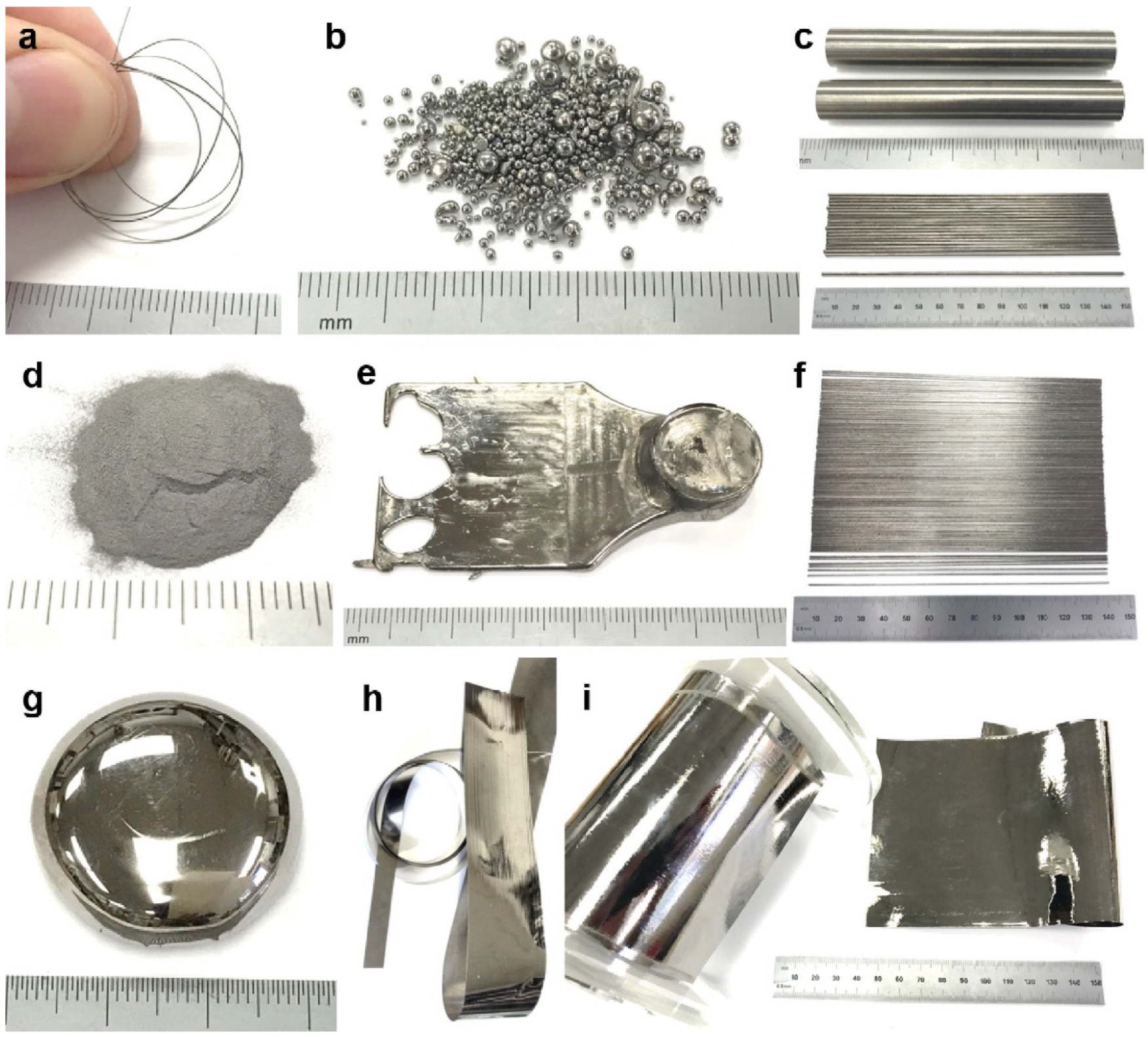
| BMG Feedstock for AM | Typical Feedstock Size (mm) | Scalable Production | Relative Cost | Oxidation and Contamination | Relevance for AM |
|---|---|---|---|---|---|
| Drawn wire | 0.3–1 | Yes | High | Yes | Low |
| Spherical shot | 0.5–5 | Yes | Low | Yes | Low |
| Large cast rod | 2–10 | No | High | No | Low |
| Powder | 0.02–0.08 | Yes | Low | Yes | High |
| Cast plates | 0.75–5 | No | High | No | Low |
| Thin cast rods | 0.5–1 | No | High | No | Low |
| Melt spun ribbon | 0.01–0.05 | Yes | Low | No | Low |
| Metal sheet | 0.1–1 | Yes | Low | No | High |
| Material | Ref. | Method | Parameters |
|---|---|---|---|
| AMZ4 | [5] | LPBF | P, h, t |
| AMZ4 | [56] | LPBF | P |
| AMZ4 | [69] | LPBF | Inert gas |
| AMZ4 | [78] | LPBF | Border power and distance |
| Al85Ni5Y6Co2Fe2 | [54] | LPBF | Scanning strategy |
| Fe68.3C6.9Si2.5B6.7P8.7Cr2.3Mo2.5Al2.1 | [76] | LPBF | P, v |
| Zr52.5Ti5Cu17.9Ni14.6Al10-LM105 | [85] | LPBF | P, v, h, Scanning strategy |
| Zr52.5Cu17.9Ni14.6Al10Ti5-LM105 | [33] | LPBF | P, v, h |
| Fe43.7Co7.3Cr14.7Mo12.6C15.5B4.3Y1.9 | [35] | LPBF | P, v |
| Fe43.7Co7.3Cr14.7Mo12.6C15.5B4.3Y1.9 | [38] | LPBF | P, v |
| FeCrMoBC | [42] | LPBF | P, v, h, Scanning strategy |
| FeCrMoBC | [59] | LPBF | Scanning strategy |
| FeCrMoBC | [100] | DED | P, v |
| Fe49.60Cr18.10Mn1.90Mo7.40W1.60B15.80C3.82Si2.40 | [44] | LPBF | P |
| Zr57.4Ni8.2Cu16.4Ta8Al10 | [46] | LPBF | P, v |
| Cu50Zr43Al7 | [52] | LPBF | P, v |
| Fe73.7Si11B11C2Cr2.28 | [62] | LPBF | Scanning strategy |
| Cu46Zr47Al6Co1 | [60] | LPBF | h |
| Zr55Cu30Al10Ni5 | [61] | LPBF | pre-annealing of the powder |
| FeCoBSiNb | [68] | LPBF | P, v |
| Zr55Cu30Al10Ni5 | [93] | LSF | Powder size |
| Zr44Ti11Cu10Ni10Be25 | [94] | LSF | v |
| Zr50Ti5Cu27Ni10Al8 | [97] | DED | P, v |
| Zr51Ti5Cu25Ni10Al9 | [101] | DED | P |
| Zr39.6Ti33.9Nb7.6Cu6.4Be12.5, DH3 | [102] | DED | P, v |
| Zr51 BMG | [104] | DED | P, v |
| Zr52.5Ti5Cu17.9Ni14.6Al10-LM105 | [107] | LFP | P, v |
| Zr52.5Ti5Cu17.9Ni14.6Al10-LM105 | [108] | LFP | v, h |
| Zr52.5Ti5Cu17.9Ni14.6Al10-LM105 | [109] | LFP | v |
| Zr52.5Ti5Cu17.9Ni14.6Al10-LM105 | [110] | LFP | v |
| Alloy | Process Method | Hardness (HV) | Load (kgf) | Structure | Ref. |
|---|---|---|---|---|---|
| AMZ4 | LPBF | 438 | 2 | Amorphous | [34] |
| AMZ4 | LPBF | 466 | 1 | Amorphous | [53] |
| AMZ4 | LPBF | 484 469 466 | 5 0.5 0.05 | Amorphous | [63] |
| AMZ4 | LPBF | 465 455 446 | 1 2 5 | Highly amorphous | [32] |
| Zr60.14Cu22.31Fe4.85Al9.7Ag3 | LPBF | 425 | 0.5 | Amorphous | [50] |
| Zr50Cu50 | LPBF | 593 462 | 0.05 | Amorphous Crystallized | [74] |
| FeSiBCrC | LPBF | 900 | 0.1 | Crystallized | [75] |
| FeCrMoBC | DED | 640 1400 | 2 | Amorphous Crystallized | [100] |
| Pd43Cu27Ni10P20 | LPBF | 498 | 1 | Amorphous | [73] |
| Zr65Cu17.5Ni10Al7.5 | LFP | 418 430 398 | 0.025 0.1 2 | Amorphous | [28] |
| Zr52.5Ti5Al10Ni14.6Cu17.9-LM105 | LFP | 563 | 0.05 | Amorphous | [107] |
| Alloy | Ref. | Fabrication Method | σy (MPa) | σmax (MPa) | εp (%) | Size (mm3) | Comment |
|---|---|---|---|---|---|---|---|
| Zr52.5Ti5Cu17.9Ni14.6Al10-LM105 | [85] | LPBF | 1500 | 1500 | 0 | Ø3 × 6 | |
| Zr55Cu30Al10Ni5 | [86] | LPBF | 1504 ± 103 | 1504 ± 103 | 0 | Ø3 × 6 | |
| Zr52.5Ti5Cu17.9Ni14.6Al10-LM105 | [33] | LPBF | 1623 ± 52 | 1623 ± 52 | <0.5 | Ø3 × 6 | |
| Zr50Ti5Cu27Ni10Al8 | [97] | DED | 2550 ± 180 | 2700–2840 | <1 | Ø0.003 × 0.006 | |
| Zr57.4Ni8.2Cu16.4Ta8Al10 | [46] | LPBF | 1710 ± 39 | 1932 ± 37 | 2.15 ± 0.25 | Ø1.5 × 3 | Including ductile phase, Ta |
| Zr55Cu30Al10Ni5 | [95] | LSF | 1266–1452 | 1266–1452 | 0 | Ø3 × 6 | |
| AMZ4 | [53] | LPBF | 1820 ± 50 | 1860 ± 50 | 2.03 ± 0.04 | Ø0.002 × 0.005 | |
| AMZ4 | [32] | LPBF | 1368 ± 41 | 1368 ± 41 | 0 | Ø6 × 9 | |
| Zr52.5Cu17.9Ni14.6Al10Ti5 | [57] | LPBF | 1710 ± 40 | 1710 ± 40 | 0.5 | Ø3 × 6 | |
| 1420 ± 20 | 1540 ± 10 | <0.2 | 3 × 3 × 6 | ||||
| Zr55Cu30Al10Ni5 | [58] | LPBF | 1499 | 1499 | 0 | Ø3 × 6 | As-built |
| 491 | 491 | Heat treated | |||||
| Ti47Cu38Zr7.5Fe2.5Sn2Si1Ag2 | [39] | LPBF | 1690 ± 50 | 1690 ± 50 | 0 | Ø2 × 4 | |
| Pd47Cu23Ni10P20 | [73] | LPBF | 1138 ± 78 | 1138 ± 78 | 0 | Ø4 × 6 | |
| Fe55Cr25Mo16B2C2 | [49] | LPBF | 4500 | 6000 | <2 | Ø0.0015 × 0.003 | |
| Al85Nd8Ni5Co2 | [84] | LPBF | 940 | 1080 | 2.45 | N.A | |
| Cu46Zr47Al6Co1 | [60] | LPBF | 940 | 940 | 0 | N.A | Composite |
| Cu50Zr43Al7 | [52] | LPBF | 1044 | 1044 | 0 | Ø4 × 8 | |
| Cu/FeCrMoCB | [64] | LPBF | 780 ± 10 | 885 ± 2 | 2.77 | Ø3 × 6 | 40% Cu |
| 777 ± 4 | 857 ± 2 | 3.88 | 50% Cu | ||||
| Zr50Cu50 | [74] | LPBF | 957 | 1841 | 3.17 | Ø2 × 4 | Composite |
| Zr60.14Cu22.31Fe4.85Al9.7Ag3 | [50] | LPBF | 1607 ± 14 | 1734 ± 30 | 1.43 ± 0.17 | Ø1 × 2 | |
| 1661 ± 34 | 1758 ± 18 | 0.51 ± 0.08 | Ø2 × 4 | ||||
| 1670 ± 36 | 1770 ± 17 | 0.46 ± 0.03 | Ø3 × 6 |
| Alloy | Fabrication Method | Ref. | Flexural Yield Strength (MPa) | Maximum Flexural Strength (MPa) | Testing Method | Plasticity | Protective Gas |
|---|---|---|---|---|---|---|---|
| Zr65Cu17.5Ni10Al7.5 | LFP | [28] | 1880 | 2250 | 4PB | Yes | Ar |
| AMZ4 | LPBF | [34] | 1300 | 1300 | 3PB | No | N.A |
| AMZ4 | LPBF | [69] | 1167±108 | 1167 ± 108 | 3PB | No | N2 |
| 1684 ± 116 | 1684 ± 116 | Ar | |||||
| 1693 ± 50 | 1693 ± 50 | Ar98H2 | |||||
| AMZ4 | LPBF | [71] | 2100 | 2100 | 3PB | No | Ar |
| AMZ4 | LPBF | [32] | 1666 ± 33 | 1666 ± 33 | 3PB | No | N2 |
Publisher’s Note: MDPI stays neutral with regard to jurisdictional claims in published maps and institutional affiliations. |
© 2021 by the authors. Licensee MDPI, Basel, Switzerland. This article is an open access article distributed under the terms and conditions of the Creative Commons Attribution (CC BY) license (https://creativecommons.org/licenses/by/4.0/).
Share and Cite
Sohrabi, N.; Jhabvala, J.; Logé, R.E. Additive Manufacturing of Bulk Metallic Glasses—Process, Challenges and Properties: A Review. Metals 2021, 11, 1279. https://doi.org/10.3390/met11081279
Sohrabi N, Jhabvala J, Logé RE. Additive Manufacturing of Bulk Metallic Glasses—Process, Challenges and Properties: A Review. Metals. 2021; 11(8):1279. https://doi.org/10.3390/met11081279
Chicago/Turabian StyleSohrabi, Navid, Jamasp Jhabvala, and Roland E. Logé. 2021. "Additive Manufacturing of Bulk Metallic Glasses—Process, Challenges and Properties: A Review" Metals 11, no. 8: 1279. https://doi.org/10.3390/met11081279
APA StyleSohrabi, N., Jhabvala, J., & Logé, R. E. (2021). Additive Manufacturing of Bulk Metallic Glasses—Process, Challenges and Properties: A Review. Metals, 11(8), 1279. https://doi.org/10.3390/met11081279