Article

Wire Arc Additive Manufacturing with Novel Al-Mg-Si Filler Wire—Assessment of Weld Quality and Mechanical Properties

by
René Winterkorn
1,2,*,†,
Andreas Pittner
1,2,† and
Michael Rethmeier
1,2
1
Institut für Werkzeugmaschinen und Fabrikbetrieb IWF, Technische Universität Berlin, FG Fügetechnik Straße des 17. Juni 135, 10623 Berlin, Germany
2
Bundesanstalt für Materialforschung (BAM), Unter den Eichen 87, 12205 Berlin, Germany
*
Author to whom correspondence should be addressed.
These authors contributed equally to this work.
Metals 2021, 11(8), 1243; https://doi.org/10.3390/met11081243
Submission received: 24 June 2021 / Revised: 22 July 2021 / Accepted: 27 July 2021 / Published: 5 August 2021
(This article belongs to the Topic Additive Manufacturing)

Abstract

:
Wire arc additive manufacturing enables the production of near-net shape large-volume metallic components leveraging an established industrial base of welding and cladding technology and adapting it for layer-wise material deposition. However, the complex relationship between the process parameters and resulting mechanical properties of the components still remains challenging. In case of high-strength Al-Mg-Si aluminum alloys, no commercial filler wires are yet available due the high susceptibility of solidification cracking as well as the necessary efforts to obtain acceptable mechanical properties. To address this need, we evaluated a novel filler wire based on AlMg0.7Si doped with a Ti5B1 master alloy to foster fine equiaxed grains within the deposited metal. The correlation between the process parameters and component quality was examined by analyzing the size and distribution of pores as well as the grain morphology. Furthermore, we evaluated the influence of different post-weld heat treatment strategies to achieve mechanical properties corresponding to the reference wrought material. We demonstrated that fine equiaxed grains in the weld metal reduced the susceptibility of solidification cracking significantly. The novel AlMg0.7Si-TiB (S Al 6063-TiB) filler wire facilitated wire arc additive manufacturing of high-strength aluminum components with mechanical properties that were almost as superior as the corresponding wrought base material.

1. Introduction

Additive manufacturing plays an import role to foster the transition to more flexible [1] production paradigms and to ensure sustainable manufacturing concepts [2]. In particular, wire arc additive manufacturing (WAAM) allows the near-net shape production of large-volume metallic components by applying an electric arc and a protective shielding gas to melt a filler wire, thereby, enabling a layer-wise material deposition. WAAM allows for high deposition rates of several kg/h and a broad variety of metals to be used depending on the availability of corresponding wires that can be utilized for arc welding processes, such as tungsten inert gas welding (TIG) or gas metal arc welding (GMAW).
The additive manufacturing of large-volume components makes WAAM one of the direct energy deposition processes with the lowest achievable “buy-to-fly” ratio (BTF) and significant cost savings [3]. As a consequence, the benefits of WAAM are more likely to be realized for expensive or difficult-to-machine high performance materials, such as Ti-alloys, Ni-alloys, high-strength steels or aluminum alloys [4].
In this context, high-strength precipitation hardening aluminum alloys (series 2xxx, 6xxx and 7xxx) are characterized by a superior strength-to-weight ratio that offers a wide range of applications from automotive [5], ship and pipeline construction [6] to aviation [7]. However, wire arc additive manufacturing of aluminum alloys still remains challenging due to the complex relationship between the arc characteristics, production boundary conditions and resulting component quality [8]. The main issues that need to be addressed are the risk of pore formation due to the high solubility and entrapment of gases, such as hydrogen; the inhomogeneous microstructure; and the high risk of solidification cracking [9].
The aluminum alloys Al-Si (series 4xxx) and Al-Mg (series 5xxx) are characterized by a sufficient weldability, which can directly be utilized for WAAM applications [10,11]. The corresponding 4xxx and 5xxx welding wires resulted in components with low strength values compared to precipitation hardening aluminum alloys. A few researchers analyzed the applicability of series 2xxx wires for WAAM. Xiaoyu et al. realized a layer-wise deposition of AA 2219 under the action of a gas tungsten arc. They showed that, if an appropriate post weld heat treatment (PWHT) was selected, hardness values could be increased up to 97% [12]. Jianglong Gu et al. investigated the effect of various welding processes on the porosity of generated walls using Al-Cu6Mn (AA 2319) and showed that low energy processes with a reversing wire electrode resulted in the lowest porosity [13].
Nevertheless, to the authors best knowledge, no WAAM applications based on aluminum alloys of series 6xxx (or 7xxx) exist, due to the lack of available filler wires for GMAW. This is mainly due to the poor weldability caused by the high susceptibility of solidification cracking of these alloys [14]. A fine-grained equiaxed weld metal reduces the risk of solidification cracking significantly [15]. In other areas of additive manufacturing, promising studies have been carried out that show that doping aluminum alloys with titanium and boron as a grain refiner leads to a reduction in grain size since the number of active nuclei is increased.
In [16], the authors demonstrated that fine equiaxed grains were formed during Selective Laser Melting (SLM) of a Al-12Si-TiB2 powder mixture. The gradual increase in the TiB2 content (1 wt.%, 2 wt.% and 5 wt.%) yielded a successive reduction in the grain size [17]. The grain refining influence of TiB2 particles on AA 7075 composites manufactured by Laser Metal Deposition (LMD) was investigated in [18]. An addition of 4 wt% TiB2 reduced the resulting grain sizes and improved the mechanical properties.
Schempp showed, in [19], that titanium and boron were also well suited to foster grain refinement in the weld metal of AW 6082. Experimental TIG bead on plate welding on conventional AW 6082 plates and the corresponding remelting of ingots made of AW 6082 doped with a AlTi5B1 master alloy indicated that solidification cracks could be avoided if a minimum TiB content was ensured [20].
However, there is a substantial potential of WAAM utilizing wires referring to aluminum alloys of series 6xxx. Li [21] used friction extruded wires of AA 6061 as feedstock for a TIG process. Only limited information concerning the grain morphology is contained in the publication. The possible presence of solidification cracks was not addressed. The need for WAAM applications using GMAW and 6xxx filler wires was further emphasized by Hirtler [22]. He suggested a hybrid approach by combining a forming and a WAAM process. The latter was used for depositing layers of AW 4047 on a forged substrate of AW 6082.
With respect to the above mentioned needs and potentials of 6xxx filler wires for WAAM applicable for GMAW processes, this paper presents the utilization of a novel filler wire made of AlMg0.7Si (AW 6063) doped with titanium and boron as a grain refiner. The corresponding welding wire S Al 6063-TiB was developed in the framework of the public funded project “Lightprint”. During the subsequent analyses the usability of this wire for WAAM is investigated regarding susceptibility for solidification cracking, size and distribution of pores and grain morphology. Furthermore, the influence of different strategies for PWHT on the mechanical properties of the resulting specimens are examined.

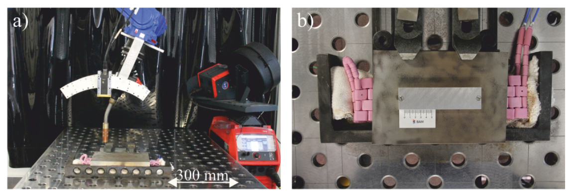
2. Materials and Methods

WAAM was performed using the equipment shown in Figure 1a. In particular, a digital arc welding source that provides the application of energy dynamic arc processes like dip transfer with reversed wire motion was used. The welding torch was mounted on a six-axis industrial robot to ensure precise and reproducible movement. Eight walls with a length and height of 150 mm as well as a thickness of around 6 mm were built. The chemical composition of the novel welding wire that is referred to as S Al 6063-TiB (in reference to DIN EN ISO 18273) is listed in Table 1.
The walls were generated on AW 6061-T6 substrate plates that were fastened on a preheatable mild steel plate as indicated in Figure 1b. The dimensions of the substrate plate were 200 mm in length, 60 mm in width and 10 mm in thickness. The substrate plate was preheated up to a temperature of 200 C to ensure a proper attachment of the initial layer. The ceramic heating pads were turned off once the preheating temperature was reached. Subsequently, the deposition of the initial layers was performed.
The first three layers require a special treatment of the process parameters to guarantee a sufficient fusion within the layers as well as the substrate plate. The final parameter setting and arc characteristic for the actual WAAM process are used from the fourth layer onwards as shown in Table 2.
The interpass time between each layer was set to 120 s. Individual layers were deposited in an alternating manner until the target height of 150 mm was reached. The generated walls cooled down to room temperature passively and were separated from the substrate plates by saw-cut.
Five material conditions were defined to consider different strategies for PWHT and to evaluate their influence on the grain morphology and strength characteristics of the additively manufactured walls. The temperatures and dwell times for solution heat treatment and artificial aging that characterize the distinct PWHT are listed in Table 3. The following strategies for PWHT were applied to distinguish different material conditions: “as welded” (AW), “artificially aged 1” (AA1), “artificially aged 2” (AA2), “solution treated and artificially aged 1” (STAA1) and “solution treated and artificially aged 2” (STAA2).
Tensile specimens of type E 3 × 8 × 30 according to DIN 50125 as well as samples for hardness tests and microstructural investigations were machined from the corresponding walls. The geometry of E 3 × 8 × 30 and the removal plans are illustrated in Figure 2.
The longitudinal tensile specimens were denoted as L1–L7, and the transversal ones as T1–T8. The samples for hardness testing and microstructural investigations were labeled as H1–H3 and M1–M3. Tensile tests were executed in accordance to DIN EN ISO 6892-1, and the corresponding axial forces and elongations of the specimens were recorded. In addition, the total local strains were measured optically using digital image correlation (DIC). Hardness tests were performed in agreement with DIN EN ISO 6507-1 using a test force of 9.807 N (HV 1). The load time was set to 10 s.

3. Results and Discussion

Figure 3a shows an additively generated wall made of S Al 6063-TiB. Specimens for the hardness tests and microstructural investigations are illustrated in Figure 3b,c.

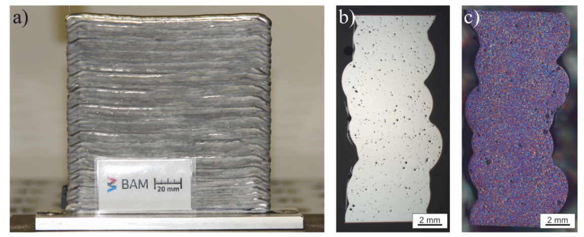
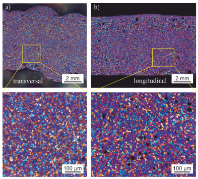
3.1. Porosity and Microstructure
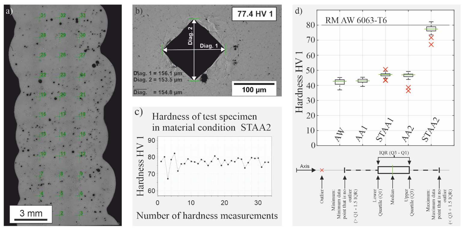
Investigations that analyze the porosity were done for the specimens H1–H3, which corresponded to material condition AW. The porosity was evaluated according to DIN EN ISO 10042. This standard is used for the weld metal of arc welded aluminum joints. However, since standards that allow a quality assessment of additively manufactured components are not yet available, the analyses of the deposited aluminum layers were done referring to DIN EN ISO 10042.
Figure 3b shows section H1 in material condition AW (H1 A W ), which yielded a fine, equally distributed porosity. The area fraction of the porosity was approximately 1.8%. The maximum diameter of a single pore was 187 μ m. Both values correlated with the best achievable quality level (B) of DIN EN ISO 10042. Two etched samples for microstructural investigations in the AW condition are illustrated as examples in Figure 4. Figure 4a includes the transversal section (M1 A W , l o n g ). The longitudinal section is depicted in Figure 4b (M2 A W , t r a n s ).
Both Figure 4a,b show evenly distributed small grains, which indicate an equiaxed solidification. This solidification mode leads, as proven in [20] for AW 6082, to a reliable reduction of the solidification cracking susceptibility and is the prerequisite for wire arc additive manufacturing utilizing the novel S Al 6063-TiB. A total of five WAAM test specimens comprising the material conditions AW, AA1, AA2, STAA1 and STAA2 as well a reference specimen extracted from a bought piece of the RM (AW 6063-T6) were examined with regards to their grain size. Three microsections were taken from each specimen, resulting in a total of eighteen analyzed microsections. Figure 5 depicts one representative microsection for the material conditions that were taken into account.
Table 4 lists the mean grain sizes for each microsection as well as the cumulative mean grain size for the five different material conditions and the RM. A comparison of the mean grain sizes shows that there is a pronounced influence of the PWHT on the mean grain size of the WAAM specimen. In particular, the material conditions STAA1 and STAA2 were characterized by a significant grain growth. The cumulative mean grain size ranged from around 24.4 ± 13.2 μ m in the material condition AA1 to 33.2 ± 19.6 μ m in material condition STAA1, which is in agreement with [20]. In comparison to the reference specimen (RM) or AW 6063-T6, the additively manufactured specimens made of AW 6063TiB yielded a grain size that was approximately 60% smaller.

3.2. Hardness Tests

Hardness was tested for the WAAM samples in the five defined material conditions. Figure 6 illustrates the results of the hardness tests of the additively manufactured AW 6063TiB specimens comparing them to the required hardness of the reference material AW 6063-T6 according to EN 755-2.
The pattern of the hardness measurements is shown in Figure 6a. In total, 33 measurements with a grid-width of 1.5 mm were done to account for statistical requirements. Figure 6b presents the 20x magnification of a hardness indentation on a WAAM sample for material condition STAA2. The green lines mark the corner points of the indentation. The diagonals were measured. The hardness HV 1 can be calculated from the mean value of the diagonals. Figure 6c depicts all 33 hardness values determined for WAAM samples in material condition STAA2. The box plots presented in Figure 6d were generated for all PWHT material conditions taken into account using the prior generated hardness values.
The median of the hardness values for specimens in material condition AW was at 42.7 HV 1. The PWHT referring to the material condition AA1 had no significant influence on the hardness values. The PWHT resulting in condition STAA1 and AA2 yielded an increase in hardness, which induced 10% higher median values. The PWHT strategy characterizing condition STAA2 exerted a major effect on the hardness of the additively manufactured components. It increased to 77.4 HV 1, which is an increase of 81.3%. This corresponds to 86.3% of the hardness of the reference material AW 6063-T6, represented by the horizontal line.

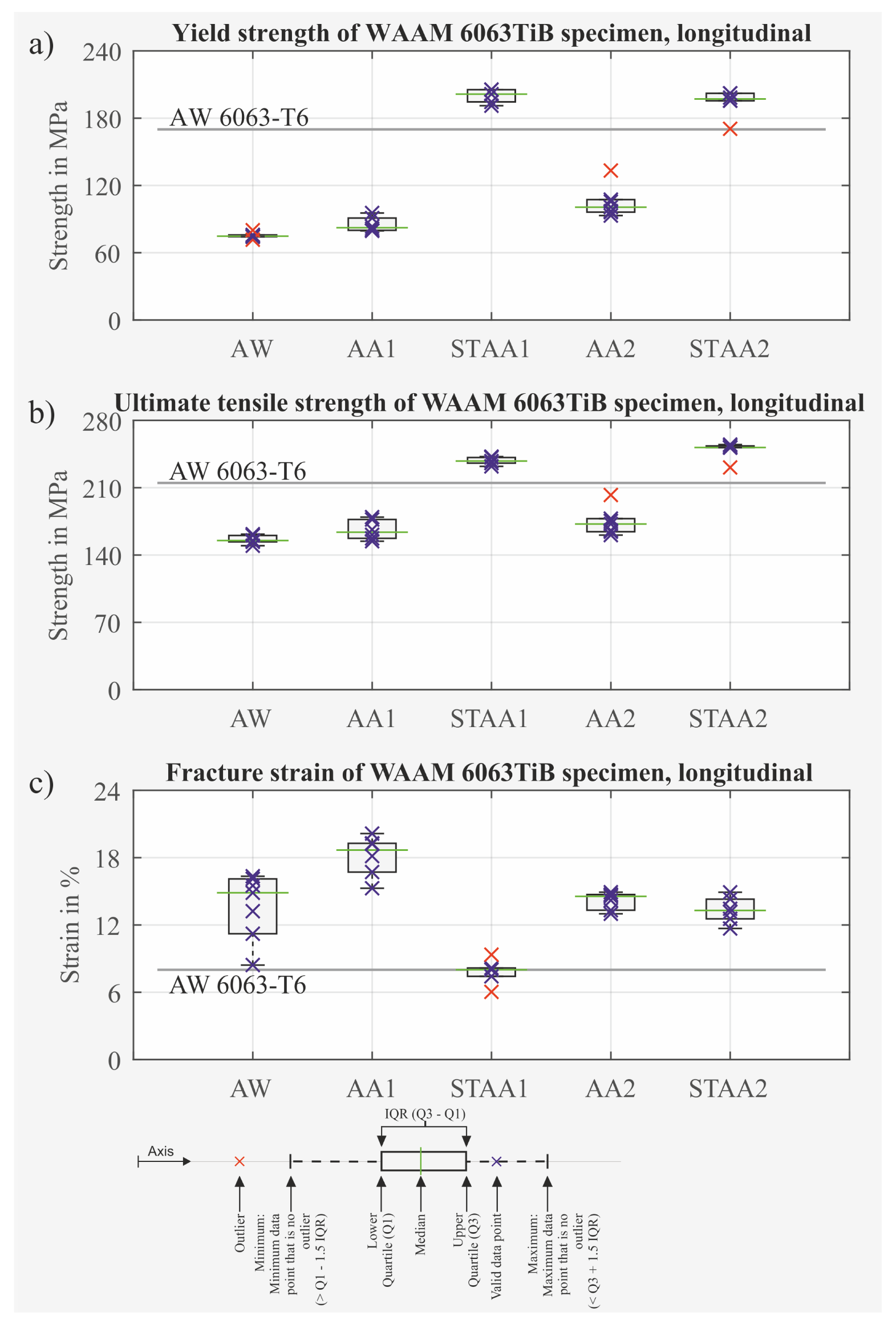
3.3. Yield Strength, Ultimate Tensile Strength and Fracture Strain

At least five tensile samples were analyzed for each combination of PWHT material condition and sample orientation. The yield strength (YS), ultimate tensile strength (UTS) and fracture strain (FS) of the tensile specimens were compared by means of their associated box plots. The horizontal line indicates the required value for the reference wrought material AW 6063-T6 according to EN 755-2. The values for YS, UTS and FS refer to the associated medians, which are marked by the green lines in the box plots. They are also listed in Table 5.

3.3.1. Longitudinal Tensile Specimens

Figure 7 shows the box plots of the YS, UTS and FS for the longitudinal specimens. Figure 7a depicts the YS. The artificial aging providing the material conditions AA1 and AA2 only has a slight influence on the YS of the longitudinal specimens. Both values are much lower than the requested YS of 170 MPa. On the other hand, solution treatment and artificial aging resulting in STAA1 and STAA2 had a significantly increasing influence on the YS.
Figure 7b visualizes a similar behavior for the UTS for the longitudinal specimens. While the artificial aging was not capable of improving the UTS of longitudinal specimens to meet the required strength of 215 MPa, solution treatment and subsequent artificial aging increased the UTS significantly. The highest UTS was achieved for the STAA2 condition.
The FS of the longitudinal specimens is presented in Figure 7c. The initially high FS for the specimens in the AW condition can be enhanced even further by artificial aging. On the other hand, the specimens in material condition STAA1 showed a drastically reduced ductility, resulting in a FS of 8%. This corresponds to the minimum required value according to EN 755-2. A heat treatment yielding STAA2 condition had a slight influence on the FS and decreased it by approximately 10%.
Table 5 lists the median YS, median UTS and median FS for the investigated material conditions. Summing up the results for the longitudinal tensile specimens, we concluded that both PWHT’s yielding STAA1 or STAA2 increase the yield strength above the required YS according to EN 755-2. The highest YS was achieved with specimens in material condition STAA1. The UTS can also be raised above the requested UTS. However, the samples in condition STAA2 exhibited the highest UTS values. The most significant deviation between STAA1 and STAA2 was found for the FS. While the specimens in material condition STAA1 barely met the requested value of 8% FS, the specimens in material condition STAA2 yielded an FS that lay 66.2% above that value.
The WAAM specimens in material condition STAA2, which corresponds well to the PWHT presented by [23] for AW 6063 and [24] for AW 6082, leads to excellent mechanical properties for AW 6063TiB as well. Consequently, it will be regarded as the reference PWHT strategy for the subsequent analyses.

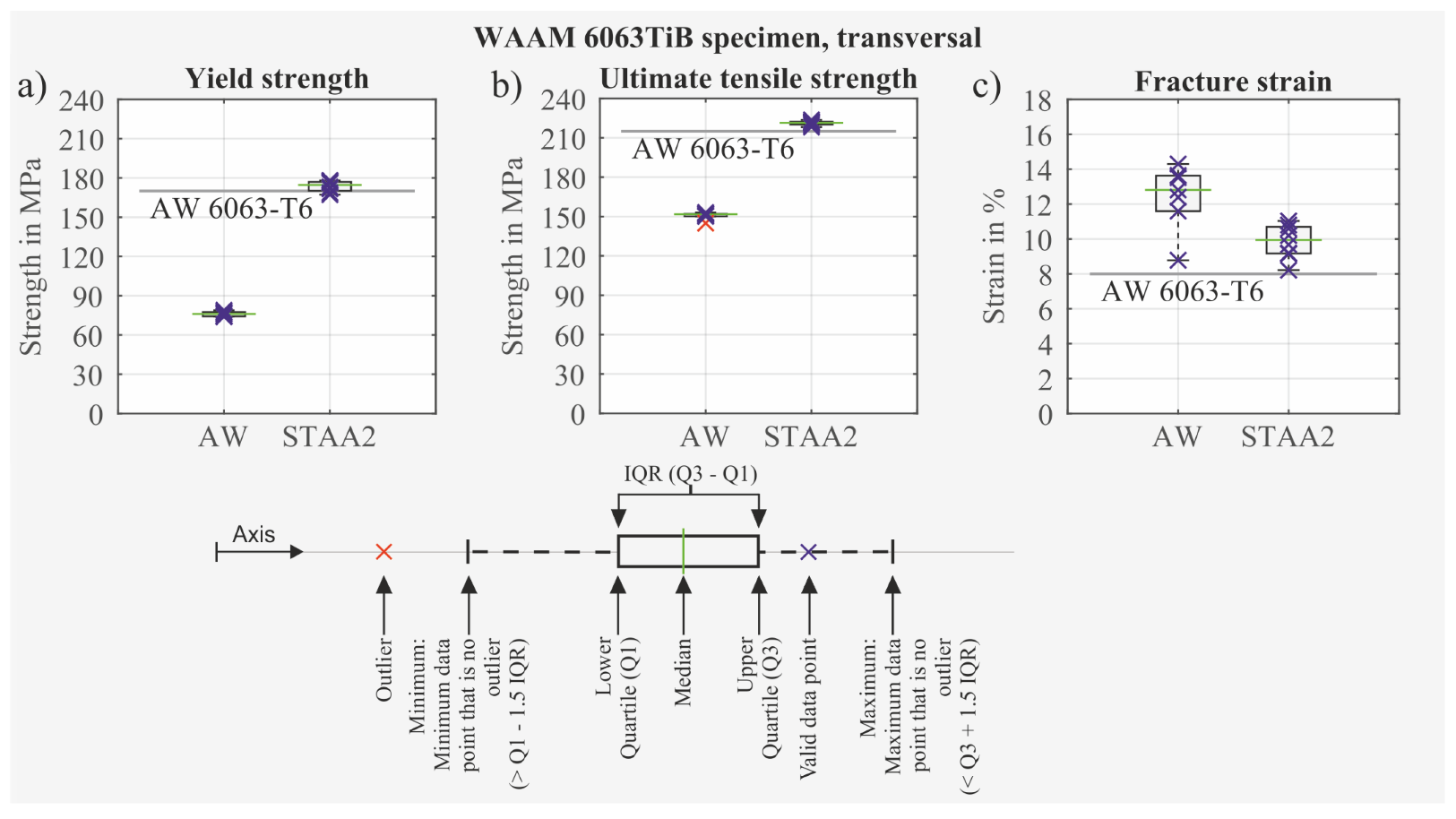
3.3.2. Transversal Tensile Specimens

Figure 8 presents the box plots for the transversal specimens. The median values are listed in Table 6.
The YS is depicted in Figure 8a. As for the longitudinal case, the YS of the transversal specimens corresponding to PWHT STAA2 increased significantly. The requested YS according to EN 755-2 (170 MPa) was exceeded.
The same behavior was observed for the UTS. This is presented in Figure 8b. The UTS of the transversal specimens can be increased above the required value of 215 MPa by applying a solution treatment followed by artificial aging causing the material condition STAA2. The results for the FS are illustrated in Figure 8c. The initially high FS of the samples in the AW condition decreased by applying the PWHT that referred to material condition STAA2. This resulted in a significant loss of ductility. Nevertheless, the requirement of 8% FS was clearly exceeded by the transversal specimens in the material condition STAA2.
Summing up the results, the requested values for the mechanical strength properties (YS, UTS and FS) of the reference material AW 6063-T6 according to EN 755-2 were also met by the transversal AW 6063TiB specimens for PWHT condition STAA2.

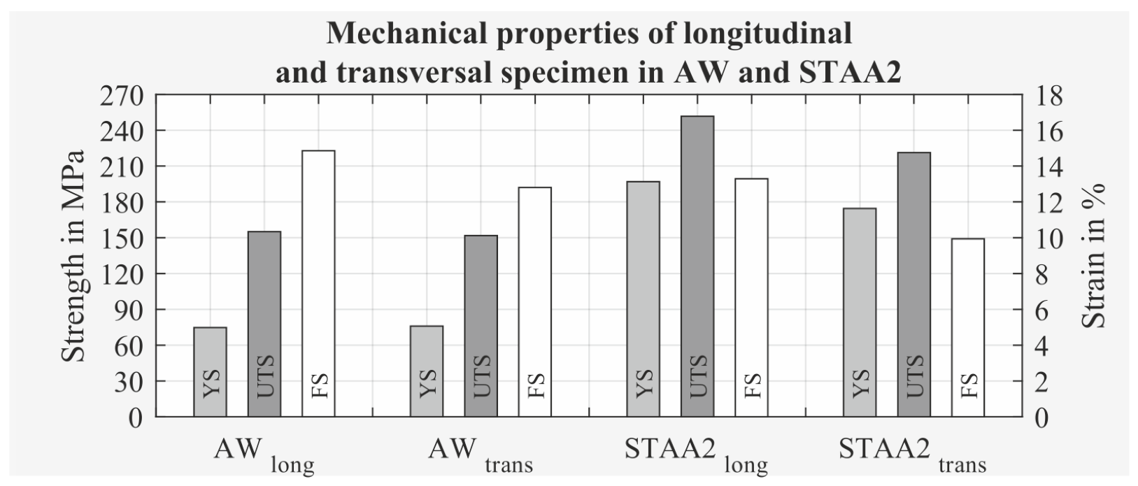
3.3.3. Longitudinal versus Transversal Tensile Specimens

A direct comparison of the YS, UTS and FS is given in Figure 9. The two groups of columns on the left side depict the mechanical properties for the AW condition. Concerning the YS and UTS of the specimens, there was almost no directional dependence, whereas this was clearly pronounced for the FS. The transversal specimens only yielded 86% FS in comparison to the longitudinal specimens.
The two groups of columns on the right side present the mechanical properties of the WAAM specimens in the material condition STAA2. The directional dependence for the STAA2 condition is much more apparent. Y S S T A A 2 , t r a n s corresponded to only 89% of Y S S T A A 2 , l o n g . The UTS showed a similar behavior. The U T S S T A A 2 , t r a n s was equivalent to approximately 88% U T S S T A A 2 , l o n g . As in the AW condition, the FS revealed the greatest directional dependence. F S S T A A 2 , t r a n s was 25% smaller than F S S T A A 2 , l o n g .
YS, UTS and FS in both the longitudinal and transversal direction fulfilled and even exceeded the requirements of EN 755-2.

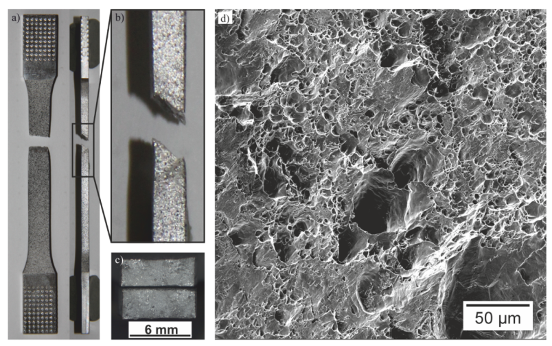
3.4. Fracture Mode of Tensile Specimens in Material Condition STAA2

A fractured longitudinal tensile specimen in material condition STAA2 is depicted in Figure 10.
For this specimen, the FS was about 13%. The plastic deformation can be recognized by the necking around the fracture (Figure 10a). All investigated tensile specimens had fracture surfaces that were oriented at a 45 angle to the load direction (Figure 10a,b). Figure 10c illustrates the matte fracture surfaces of the specimen. A magnified section of this area is presented in the scanning electron microscope image in Figure 10d. It shows a dimpled structure, which is a further indication for ductile fracture behavior.
All these results prove that the current fracture type is a shear fracture, which appears promising in terms of the toughness characteristics and in-service behavior of WAAM samples made of AW 6063TiB.

4. Conclusions

A novel TiB alloyed AlMg0.7Si welding wire (S Al 6063-TiB) was utilized for wire arc additive manufacturing. The weldability of the wire was evaluated based on the porosity, grain morphology and hot cracking susceptibility. In particular, a sufficient low porosity of approximately 1.8% was observed within the deposited weld metal. The specimens can be assigned to the best quality level (B). The titanium- and boron-doped aluminum filler wire resulted in an equiaxed, fine-grained weld metal, which, in turn, led to the avoidance of solidification cracks, which was proven for all analyzed microsections.
The requested mechanical strength properties of the additively manufactured specimens were achieved by a subsequent heat treatment. Tensile tests according to DIN EN ISO 6892-1 were performed utilizing longitudinally and transversally to the build-direction extracted specimens. For both the transversal as well as the longitudinal specimens, the values for the yield strength, ultimate tensile strength and fracture strain met and even exceeded the requirements of the corresponding wrought reference material AW 6063-T6. The fracture strain, as well as analysis of the fracture mode, showed a ductile behavior yielding promising toughness characteristics.
The successful utilization of the novel filler wire S Al 6063-TiB to WAAM facilitated the additive manufacturing of large components of high-strength aluminum alloys.

Author Contributions

Conceptualization, R.W. and A.P.; methodology, R.W. and A.P.; software, R.W.; validation, R.W. and A.P.; investigation, R.W. and A.P.; resources, A.P. and M.R.; data curation, R.W.; writing—original draft preparation, R.W.; writing—review and editing, R.W., A.P. and M.R.; visualization, R.W.; project administration, R.W. and A.P.; funding acquisition, A.P. and R.W. All authors have read and agreed to the published version of the manuscript.

Funding

This research was funded by the Federal Ministry of Education and Research of Germany grant number 01LY1615D.

Conflicts of Interest

The authors declare no conflict of interest.

References

  1. Bogers, M.; Hadar, R.; Bilberg, A. Additive manufacturing for consumer-centric business models: Implications for supply chains in consumer goods manufacturing. Technol. Forecast. Soc. Chang. 2016, 102, 225–239. [Google Scholar] [CrossRef]
  2. Sauerwein, M.; Doubrovski, E.; Balkenende, R.; Bakker, C. Exploring the potential of additive manufacturing for product design in a circular economy. J. Clean. Prod. 2019, 226, 1138–1149. [Google Scholar] [CrossRef]
  3. Ding, D.; Pan, Z.; Cuiuri, D.; Li, H. Wire-feed additive manufacturing of metal components: Technologies, developments and future interests. Int. J. Adv. Manuf. Technol. 2015, 81, 465–481. [Google Scholar] [CrossRef]
  4. Williams, S.W.; Martina, F.; Addison, A.C.; Ding, J.; Pardal, G.; Colegrove, P. Wire + Arc Additive Manufacturing. Mater. Sci. Technol. 2015, 32, 641–647. [Google Scholar] [CrossRef] [Green Version]
  5. Miller, W.; Zhuang, L.; Bottema, J.; Wittebrood, A.; De Smet, P.; Haszler, A.; Vieregge, A. Recent development in aluminium alloys for the automotive industry. Mater. Sci. Eng. A 2000, 280, 37–49. [Google Scholar] [CrossRef]
  6. Elangovan, K.; Balasubramanian, V. Influences of post-weld heat treatment on tensile properties of friction stir-welded AA6061 aluminum alloy joints. Mater. Charact. 2008, 59, 1168–1177. [Google Scholar] [CrossRef]
  7. Cong, B.; Ding, J.; Williams, S. Effect of arc mode in cold metal transfer process on porosity of additively manufactured Al-6.3%Cu alloy. Int. J. Adv. Manuf. Technol. 2015, 76, 1593–1606. [Google Scholar] [CrossRef]
  8. Derekar, K.S. A review of wire arc additive manufacturing and advances in wire arc additive manufacturing of aluminium. Mater. Sci. Technol. 2018, 34, 895–916. [Google Scholar] [CrossRef]
  9. Thapliyal, S. Challenges associated with the wire arc additive manufacturing (WAAM) of aluminum alloys. Mater. Res. Express 2019, 6, 112006. [Google Scholar] [CrossRef]
  10. Gierth, M.; Henckell, P.; Ali, Y.; Scholl, J.; Bergmann, J.P. Wire Arc Additive Manufacturing (WAAM) of Aluminum Alloy AlMg5Mn with Energy-Reduced Gas Metal Arc Welding (GMAW). Materials 2020, 13, 2671. [Google Scholar] [CrossRef]
  11. Köhler, M.; Fiebig, S.; Hensel, J.; Dilger, K. Wire and Arc Additive Manufacturing of Aluminum Components. Metals 2019, 9, 608. [Google Scholar] [CrossRef] [Green Version]
  12. Cai, X.; Dong, B.; Bai, J.; Lin, S.; Fan, C.; Yang, C. Effects of post-deposition heat treatment on microstructures of GTA-additive manufactured 2219-Al. Sci. Technol. Weld. Join. 2019, 81, 1–10. [Google Scholar] [CrossRef]
  13. Gua, J.; Conga, B.; Dinga, J.N.; Williamsa, S.W. Wire + Arc Additive Manufacturing Of Aluminium. 2014. Available online: https://www.semanticscholar.org/paper/WIRE-%2B-ARC-ADDITIVE-MANUFACTURING-OF-ALUMINIUM-Gua-Conga/289a5b7d6d2f015c74ec424911a1ccf84f1a04f0 (accessed on 24 June 2021).
  14. Huang, C.; Kou, S. Liquation Cracking in Full-Penetration Al-Mg-Si Welds: A higher fraction solid in the weld metal than in the partially melted zone during terminal solidification is a necessary condition for cracking to occur. Weld. J. 2004, 83, 111–122. [Google Scholar]
  15. Kou, S. Solidification and liquation cracking issues in welding. JOM 2003, 55, 37–42. [Google Scholar] [CrossRef]
  16. Xi, L.; Wang, P.; Prashanth, K.G.; Li, H.; Prykhodko, H.; Scudino, S.; Kaban, I. Effect of TiB2 particles on microstructure and crystallographic texture of Al-12Si fabricated by selective laser melting. J. Alloys Compd. 2019, 786. [Google Scholar] [CrossRef]
  17. Xi, L.; Gu, D.; Guo, S.; Wang, R.; Ding, K.; Prashanth, K.G. Grain refinement in laser manufactured Al-based composites with TiB2 ceramic. J. Mater. Res. Technol. 2020, 9, 2611–2622. [Google Scholar] [CrossRef]
  18. Lei, Z.; Bi, J.; Chen, Y.; Chen, X.; Tian, Z.; Qin, X. Effect of TiB2 content on microstructural features and hardness of TiB2/AA7075 composites manufactured by LMD. J. Manuf. Process. 2020, 53, 283–292. [Google Scholar] [CrossRef]
  19. Schempp, P.; Tang, Z.; Cross, C.; Pittner, A.; Seefeld, T.; Rethmeier, M. Influence of Alloy and Solidification Parameters on Grain Refinement in Aluminum Weld Metal due to Inoculation. In Proceedings of the 9th International Conference, ASM International, Materials Park, OH, USA, 4–8 June 2012. [Google Scholar]
  20. Schempp, P.; Cross, C.E.; Schwenk, C.; Rethmeier, M. Influence of Ti and B Additions on Grain Size and Weldability of Aluminium Alloy 6082. Weld. World 2012, 56, 95–104. [Google Scholar] [CrossRef]
  21. Li, X.; Reynolds, A.P.; Baoqiang, C.; Jialuo, D.; Williams, S. Production and Properties of a Wire-Arc Additive Manufacturing Part Made with Friction Extruded Wire. In TMS2015 Supplemental Proceedings; John Wiley & Sons, Ltd.: Hoboken, NJ, USA, 2015; pp. 445–452. [Google Scholar] [CrossRef]
  22. Hirtler, M.; Jedynak, A.; Sydow, B.; Sviridov, A.; Bambach, M. A study on the mechanical properties of hybrid parts manufactured by forging and wire arc additive manufacturing. Procedia Manuf. 2020, 47, 1141–1148. [Google Scholar] [CrossRef]
  23. Nandy, S.; Bakkar, M.A.; Das, D. Influence of Ageing on Mechanical Properties of 6063 Al Alloy. Mater. Today Proc. 2015, 2, 1234–1242. [Google Scholar] [CrossRef]
  24. Scott, M.H.; Gittos, M.F. Tensile and Toughness Properties of Arc-Welded 5083 and 6082 aluminum Alloys: CTOD and CCT test results are a possibility for the prediction of permissible discontinuity sizes in welded aluminum structures. Weld. Res. 1983, 62, 243–252. [Google Scholar]
Figure 1. (a) Welding equipment, (b) heating and substrate plate.
Metals 11 01243 g001
Figure 2. The removal plan and geometry of specimens used for tensile and hardness tests as well as for the analysis of microstructure.
Metals 11 01243 g002
Figure 3. (a) WAAM wall made of S Al 6063-TiB, (b) unetched section H1 A W and (c) etched section M1 A W .
Metals 11 01243 g003
Figure 4. (a) Transversal section M1 A W , l o n g and (b) longitudinal section M2 A W , t r a n s .
Metals 11 01243 g004
Figure 5. The microstructure and mean grain size of WAAM samples for different PWHT conditions in comparison to the wrought base material AW 6063-T6.
Metals 11 01243 g005
Figure 6. (a) Cross-section with the pattern of hardness indentations, (b) visualization of the hardness indent, (c) hardness HV 1 of the test specimen in material condition STAA2 and (d) hardness HV 1 of WAAM samples in different material conditions compared to the hardness of the RM AW 6063-T6.
Metals 11 01243 g006
Figure 7. The strength properties of longitudinal WAAM AW 6063TiB specimens for different PWHT strategies (a) yield strength, (b) ultimate tensile strength and (c) fracture strain.
Metals 11 01243 g007
Figure 8. Strength properties of transversal WAAM AW 6063TiB specimens for different PWHT strategies (a) yield strength, (b) ultimate tensile strength and (c) fracture strain.
Metals 11 01243 g008
Figure 9. The mechanical properties of longitudinal and transversal specimens in AW and STAA2.
Metals 11 01243 g009
Figure 10. Fracture mode of tensile specimens: (a) front- and side view, (b) fracture zone (side view), (c) fracture surfaces and (d) fracture surface with 1000× magnification.
Metals 11 01243 g010
Table 1. Chemical composition of welding wire and reference material.
MaterialChemical Composition in Mass%
Welding wire
“S 6063-TiB”
SiCrZnCuFeAl
0.3650.1120.0094<0.0010.022
MgMnNbTiBbal.
1.170.0170.0220.3170.051
Reference material
AW 6063
SiCrZnCuFeAl
0.5220.00630.01740.0120.063
MgMnNbTiBbal.
0.480.034<0.010.012<0.01
Table 2. The welding parameters used for WAAM, including the initial bonding layers and the actual building process.
Layer
Number
Arc
Characteristics
Welding
Speed
in mm/s
Wire Feed
Speed
in m/min
Average
Current
in A
Average
Voltage
in V
1AlSi5,
MIG PMC,
ripple drive
55.713318.8
2AlMg4,5Mn(Zr),55.27411.8
3MIG CMT,54.87111.6
4 … nuniversal54.66811.5
Table 3. The different strategies for PWHT and resulting distinct material conditions.
SolutionizingArtificial Ageing
PWHTTemperature in CDwell
Time in h
Quenching
in Water
Temperature in CDwell
Time in h
Cooling
in Air
AWxxxxx🗸
AA1xxx1703🗸
AA2xxx16513🗸
STAA15255.5🗸1703🗸
STAA25402🗸16513🗸
Table 4. The mean grain size of WAAM specimens for different material conditions compared to RM AW 6063-T6.
Material and
Material Condition
Mean Grain Size in μ m
Section 1Section 2Section 3Cumulative
WAAM 6063TiB-AW23.5 ± 12.224.9 ± 12.829.1 ± 14.825.6 ± 13.5
WAAM 6063TiB-AA125.4 ± 13.223.9 ± 13.623.9 ± 12.724.4 ± 13.2
WAAM 6063TiB-AA228.2 ± 14.130.0 ± 16.427.7 ± 13.928.6 ± 14.9
WAAM 6063TiB-STAA133.5 ± 16.132.3 ± 21.733.7 ± 20.633.2 ± 19.6
WAAM 6063TiB-STAA229.1 ± 15.331.9 ± 18.427.1 ± 16.329.2 ± 16.8
RM AW 6063-T670.7 ± 47.470.7 ± 44.769.6 ± 54.670.3 ± 49.1
Table 5. The median values of YS, UTS and FS for the longitudinal tensile specimens.
Material ConditionYS in MPaUTS in MPaFS in %
AW7415514.9
AA18216318.7
STAA12012378.0
AA210017214.6
STAA219725113.3
Table 6. The median values of YS, UTS and FS for the transversal tensile specimens.
Material ConditionYS in MPaUTS in MPaFS in %
AW7615212.8
STAA21752219.9
Publisher’s Note: MDPI stays neutral with regard to jurisdictional claims in published maps and institutional affiliations.

