Article

Analysis of Optimization Weights for Flow Field of Internal Rotation Stabilizer Coupled with Porous Retaining Wall

1
The State Key Laboratory of Refractories and Metallurgy, Wuhan University of Science and Technology; Wuhan 430081, China
2
BAOSTEEL, China Baowu Steel Group Corp., Ltd., Shanghai 200000, China
*
Author to whom correspondence should be addressed.
Metals 2021, 11(8), 1208; https://doi.org/10.3390/met11081208
Submission received: 22 June 2021 / Revised: 23 July 2021 / Accepted: 26 July 2021 / Published: 29 July 2021

Abstract

:
In this paper, the flow field of the approximate T-shaped tundish and the removal rate of fine inclusions are improved by changing the parameters of the flow control device of the SCB (stabilizer coupling baffle) structure. Studies have shown that the synergistic effect of the DPRW (double porous retaining wall) structure and the IRS (internal rotation stabilizer) structure has excellent performance in mixing the temperature composition of the molten steel, increasing the average residence time of the molten steel, reducing the volume fraction of the dead zone, and improving the removal rate of fine inclusions. The opening method and diameter of the double-layer retaining wall have a greater impact on the flow field parameters. The larger the diameter, the more conducive to increasing the average residence time, and the smaller the diameter, the more conducive to increasing the removal rate of fine inclusions.

1. Introduction

The tundish has the function of storing and distributing molten steel in the continuous casting production process to ensure the continuity and automation of the production process. As a result, the molten steel is exposed to the atmosphere and slag environment for a long time, which increases the chance of contamination and deteriorates the quality of molten steel. In the modern continuous casting production process, in order to improve the output and yield rate of cast slabs, most of the production methods adopt higher drawing speed and mold cooling intensity. The small-sized inclusions do not have enough time to gather so that they are discretely distributed on the slab dendrite interface, and are therefore difficult to remove by rolling process after forming the slab [1].
With the expansion of the demand for high quality steel in modern production and life, higher requirements are put forward for the quality of molten steel, which gives the tundish an increasingly important role in the refining of molten steel [2]. The main functions include [3,4,5,6]:
  • Stabilizing the flow field of molten steel, reducing liquid level fluctuations, and reducing endogenous inclusions caused by secondary oxidation of molten steel;
  • Reducing the contamination of molten steel caused by foreign inclusions formed after the refractory material is eroded;
  • Improving the operating conditions of the flow field, increasing the proportion of plug flow volume, reducing the proportion of the dead zone volume fraction, and avoiding short-circuit flow;
  • Separating non-metallic inclusions and purifying molten steel;
  • Ensuring precise control of the composition, temperature, and flow field of molten steel in the tundish.
In the process of industrial development, in order to meet the production needs of different steel grades, tundishes of various configurations have been formed, which are divided into trapezoidal tundish, T-shaped tundish, similar T-shaped tundish, and ship-shaped tundish [7], etc. The traditional weir structure improves the quality of the cast slab by changing the direction of the flow field and increasing the mixing time of the molten steel in the tundish. In order to obtain an optimal flow field, the research on the configuration of DPRW structures is increasing. As one of the most common flow control devices [8,9,10], the tundish flow stabilizer is often set directly below the immersion nozzle, in addition to replacing the impact pad, to slow down the injection rate, reduce the turbulent kinetic energy, and reduce the scouring of the refractory material at the bottom of the tundish by the molten steel. It also has the function of rotating molten steel, adsorbing inclusions, and dispersing molten steel according to the structure of the stabilizer. Due to the important role of the stabilizer in the tundish metallurgy, a large number of related research has been carried out, and the stabilizer type suitable for specific production environments has been designed [11]. According to the overall configuration, the stabilizer is divided into barrel, square, and circular, and according to the shape of the inner cavity, it is divided into circular, polygonal, fringed, and non-flanged stabilizers, and can be divided into perforated and side-opening stabilizers according to whether the side is open or not [12,13].
The flow stabilizer and retaining wall structure are important means to change the flow field motion state in the tundish. A large number of related studies have shown that the change of the structure of the flow control device has an important impact on the metallurgical properties of the tundish; however, there are few studies on the influence of the SCB structure on the metallurgical properties of the tundish. Aiming to rectify this, this paper studies the evolution of the flow field operation state and the change of the removal effect of inclusions in the approximate T-type four-flow tundish under the synergistic effect of different structural parameter flow control devices.

2. Flow Control Device Structure

In this paper, the approximate T-shaped tundish is the main research body. The working capacity of the tundish is 46 t, the height of the interface between molten steel and mold powder is 800 mm, the height of the tundish is 900 mm, and the length is 8.3 m. The distance between the inner and outer outlets is 2.6 m. Approximately T-shaped four-stream tundish shape structure and size are shown in Figure 1.
The three-dimensional model established based on the SCB structure and the DPRW structure is shown in Figure 2, and the structural parameters are shown in Table 1. The IRS structure (Figure 2a) includes a diversion hole with an angle of 30° to the horizontal, four stoppers distributed at an angle of 90° around the central axis, and a circular eaves-shaped cavity. The DPRW model has twelve diversion holes with a horizontal angle of 30° on the two retaining walls. According to the distribution of the diversion holes on the front and rear retaining walls, they are divided into TIBO (top in bottom out) mode, BITO (bottom in top out) mode, and X mode.
The research goal of this paper is to explore the influence of SCB structure on the flow field movement of the tundish and the removal rate of fine inclusions. The installation positions of the DPRW structure and the IRS structure in the tundish are shown in Figure 3. The IRS model is located on the central axis directly below the immersion nozzle. The vertical section of the diversion hole is parallel to the central axis. According to related research [14], the DPRW model has the most significant impact on the performance of the tundish when placed symmetrically parallel to the central axis. The high-speed injection in the injection zone forms an internal swirling flow between the stabilizer blocks to reduce the velocity of the molten steel. When the horizontally diverging bottom molten steel stream flows to the exit flow zone, due to the blocking of the front retaining wall and the guiding effect of the diversion hole, the fluid turns into the cavity area in the middle of the retaining wall and collides between the retaining walls to form multiple eddies to extend the residence time of the molten steel stream in it. Finally, after being guided by the diversion hole of the rear retaining wall, the molten steel moves toward the steel slag interface, carrying the inclusion particles to the tundish mold powder for material exchange.

3. Governing Equations and Boundary Conditions

The metallurgical production process is a high-temperature reaction formed under the constraints of momentum transfer, heat transfer, and mass transfer. The existence of multi-phase chemical reactions makes the tundish metallurgical process have a large number of mechanisms that are still unknown. As laboratory research and on-site observation methods still lack credibility for the accuracy of high-temperature environment measurement results, the method of constructing models to simulate modern metallurgical processes has become an important research method [15,16]. According to the flow state of pipeline steel in the tundish, the following calculation conditions are proposed [17,18]:
  • The molten steel and the tracer indicator are both incompressible fluids, and the flow of molten steel is a turbulent motion with a Reynolds number greater than 2000;
  • After the pouring stage is over, the flow field of the tundish is a steady-state process, and the smooth flow of molten steel will not cause slag level fluctuations;
  • The movement of inclusions in the fluid conforms to the unidirectional fluid-solid coupling model. The change of the flow field movement mode will affect the entrapped particles, but the change of the movement trajectory of the inclusion solid has no obvious effect on the flow field flow;
  • The simplified particle model of inclusions is spherical particles, and the particle motion of inclusions is coupled to the collision growth model based on the random motion model. UDF (user-defined function) is used to set the boundary adsorption conditions. When the particles move to the inner surface of the tundish wall and the speed drops below 0.01 m/s, it is determined that the particles are adsorbed by the wall and removed to terminate the calculation.
The steady-state flow field of the tundish exhibits complex turbulent motion due to the high-speed motion of the injected molten steel. Therefore, the k ε double equation model in the form of R n g is used to calculate the molten steel flow field. Although the form of turbulence is complex and changeable, it still follows the three laws of physics, namely, the law of conservation of mass, the law of conservation of momentum, and the law of conservation of energy. Assuming that the fluid is a continuous medium, the basic equations are derived from the differential of the fluid clusters by the three laws, including the continuity equation, the momentum equation, the k ε double equation, etc. The calculation formula is as follows [19].
Continuity equation:
Δ X + ρ v i / x i
v i , v j ( i , j = 1 , 2 , 3 ) are the speeds in the X , Y , and Z directions of the three coordinate axes;   ρ is the density of the steel liquid; and x i ( i = 1 , 2 , 3 ) are the displacement in the X , Y , and Z directions of the three coordinate axes.
Momentum conservation equation (N-S equation):
Δ X v i + ρ v i v j / x j = u e f f ( v i / x j + v j / x i ) / x j G / x i
Turbulent energy dissipation rate equation:
Δ X ε ρ ε v i / x i = ( v i ε / σ k x j ) / x j + C 1 ε G k / k C 2 ρ ε 2 / k
u e f f is the effective viscosity;   G k is dynamic viscosity.
Among them:
Δ X = ρ / t
G k = v t v j ( v i / x j + v j / x i ) x i
μ e f f = μ + μ t = μ + ρ C 3 k 2 / ε
are the turbulent viscosity coefficient, μ are the laminar viscosity coefficient, C 1 = 1.43 , C 2 = 1.93 , C 3 = 0.09 , σ k = 1.0 , and σ ε = 1.3 .
The residence time distribution curve (RTD) of the fluid is an important method for data processing of the fluid movement in a closed space. Due to the randomness of the fluid movement, different molten steel streams have different trajectories in the tundish, but the residence time distribution of the fluid in each calculation unit in the tundish still obeys the statistical law, so the RTD curve can be calculated by the t a function [20,21,22], and the theoretical RTD curve is shown in Figure 4.
The parameters characterizing the flow characteristics of the tundish flow field can be calculated based on the RTD curve, such as the volume fraction of the mixing zone, the volume fraction of the piston zone, the volume fraction of the dead zone, the peak response time, and the short-circuit flow rate [23,24,25,26,27]. For a multi-flow reactor with a fluid domain volume of V and an outlet flow rate of Q , the calculation formula for the theoretical average residence time of the fluid in the closed vessel is:
t a = V / Q
The average residence time of the fluid in the closed reactor is:
t i = ( C ( t 0 ) t 0 + C ( t 1 ) t 1 + + C ( t i 1 ) t i 1 + C ( t i ) t i ) / ( C ( t 0 ) + C ( t 1 ) + + C ( t i 1 ) + C ( t i ) )
Of which twice the average residence time is t i 1 ( 0 , 2 t a ) , the average residence time is t i 2 ( 0 , ) , and C is the dimensionless volume fraction increase in the tracer per unit time.
Volume fraction of dead zone:
V d = 1 t i 1 / t a
Among them, V d is the dead zone volume fraction.
In order to ensure the continuity of continuous casting production and to ensure the quality control stability of the billet products, the ideal situation is that the temperature and composition of the molten steel flowing out of each outlet of the multi-stream tundish to the mold are the same. The difference in axis distance makes it difficult to obtain molten steel of the same composition in actual production. In order to characterize the composition deviation of molten steel flowing out of each outlet, the method of calculating the variance S is often used to investigate the consistency of the outlet stream [28].
S = ( i = 1 n ( x x ¯ ) 2 / ( n 1 ) ) 1 / 2
where n is the number of multi-stream tundish continuous casting units and x is the molten steel flow parameter monitored at the outlet, which can be the average residence time, tracer concentration and the number of inclusions escaped.
DPM model:
d v m / d t = 3 ρ v c d ( v v m ) / 4 ρ m d m + g i ( ρ m ρ ) / v m + f i
C D = a 1 + a 2 / R e + a 3 / R e 2
v is the average flow velocity of the liquid phase; v m is the velocity of the particles; ρ is the density of the liquid phase; ρ m is the density of the particles; d m is the equivalent diameter of the particles; R e is the Reynolds number; f i   ( i = x , y , z ) is the force in each direction; C D is the drag coefficient; and a 1 , a 2 , a 3 are regarded as constants in the turbulent motion of the same enclosed space.
According to the above model parameters, control equations and boundary conditions, a three-dimensional flow field model is established for the approximate T-shaped four-stream tundish. Use ICEM software (19.0, Ansys Inc., Canonsburg, PA, USA) to perform unstructured tetrahedral meshing of the model. The number of meshes in the entire fluid domain reaches twelve million units. The meshing result is shown in Figure 5. For the large-angle turbulence motion, the RNG iteration mode of FLUENT software (19.0, Ansys Inc., Canonsburg, PA, USA) is used to complete the calculation. The numerical simulation process is shown in Figure 6. The calculation of inclusions is coupled with the DPM (discrete phase mode) model on the basis of the turbulence calculation results. The convergence residual value is set to 10−5, and the calculation adopts the third-order upwind formula calculated by PISO to obtain more accurate simulation results.

4. Results and Discussion

4.1. Orthogonal Experimental Design Results

As the SCB model can have many factors affecting the flow field, the method of designing an orthogonal control group combined with analysis of variance is used to study the significance level of the influence of the structural parameters of the flow control device on the flow field. The results of variance analysis reflect the level of influence of various factors on the flow field in the tundish and the removal rate of fine inclusions. Factors with a significance level less than 0.05 have a significant impact on the flow field change. The larger the variance, the greater the impact on the observation results. Sorting according to the size of the variance can obtain the best coupling parameters of the flow control device structure.
According to related studies, four factors, the height of the stabilizer stopper, whether the stabilizer has a hole, the opening type of the double-layer retaining wall, and the opening diameter, will all have an impact on the flow field of the tundish [29,30,31,32], denoted by A, B, C, and D, respectively. The results of the experimental program combination are shown in Table 2. Using the L9 (22 × 32) form of mixed orthogonal table, nine groups of experimental programs can be obtained according to the four influencing factors, program 1 (A1B1C1D1), program 2 (A3B2C3D1), program 3. (A3B1C2D2), Plan 4 (A2B1C2D1), Plan 5 (A1B2C2D1), Plan 6 (A2B1C3D1), Plan 7 (A1B1C3D2), Plan 8 (A3B1C1D1), and Plan 9 (A2B2C1D2). The four-stream approximate T-shaped tundish without added flow control device was used as the control group, Plan 0 (A0B0C0D0).

4.2. Analysis of the Results of SCB Structure Convection Field Optimization

In order to digitally observe the influence of the change of the structure parameters of the flow control device on the flow field in the tundish, the numerical simulation results of the actual average residence time t and the dead zone ratio V d of the molten steel stream in the tundish are calculated according to Formulas 8 and 9, as shown in Table 3.
Comparing the theoretical average residence time of molten steel with the average residence time of inner and outer sides as shown in Figure 7, it can be seen that the original package flow field of Scheme 0 has no flow control device to change the direction of the flow field movement, which makes the average residence time of the molten steel at the outlet 1, which is closer to the molten steel injection zone, and much lower than the theoretical average residence time. The high-speed liquid flow passes through the mold to form a cast slab without fully mixing the composition and temperature. The residence time of the molten steel flowing out of the tundish through outlet 2 is very different from the other two sets of data. The axial distance between the outlet and the immersion nozzle becomes the main factor affecting the residence time of the molten steel, which makes the consistency of the composition of the molten steel in the different outlet areas worse, and affects the quality control of the finished steel. Comparing with Scheme 0, it can be seen that, after the SCB flow control device is installed, the average residence time measured at the water outlet of all the improved schemes is extended, and the maximum extension time reaches 100 s. The average residence time measured at the inner and outer outlets exceeds the theoretical average residence time, and the consistency of the outlets on the same side is significantly enhanced. Under the influence of the structural parameters of the flow control device in Scheme 7, the average residence time of outlet stream 1 and outlet stream 2 on the same side is the closest. The time difference between the detection of the tracer indicator at the inner water outlet and the outer water outlet is only 8 s, and the consistency of the multi-stream tundish outlet is the best.
The dispersion of the average residence time of different schemes is calculated according to Formula 10 and shown in Figure 8. It can be clearly seen that the increase in the SCB flow control device makes the dispersion of the signal interval time of the molten steel flow detected by each water outlet of the approximate T-shaped four-flow tundish significantly reduced. The degree of optimization of most of the schemes has more than doubled. Among them, the parameter optimization of Scheme 7 has the most significant impact on consistency, and the calculation results are consistent with the average residence time analysis results.
According to the orthogonal experiment scheme, the significance level of the average residence time and the volume fraction of the dead zone was analyzed, and the influence of the four factors on the performance of the tundish was studied. The analysis results are shown in Table 4. Judging by the significance level, the change of DPRW structural parameters has a significant influence on the flow field, while the influence of IRS structure is relatively low. The influence of the hole diameter in the structural parameters of DPRW is dominant. The four factors have a greater influence on the change of the volume fraction of the dead zone in the flow field. The four factors have a greater influence on the change of the volume fraction of the dead zone in the flow field in the tundish. The order of the degree of influence is D > C > A > B, namely: the diameter of the retaining wall, the method of the retaining wall, the height of the stopper of the flow stabilizer, and whether the flow stabilizer has a diversion hole has a gradually weakening effect on the volume fraction of the dead zone of the flow field. According to the results of the range calculation, the DPRW structure parameters of C3D2 are the most effective for the optimization of the flow field in the tundish. The optimization degree of the flow field in Scheme 7 (A1B1C3D2) has been confirmed in the above analysis. The influence of structural parameters on the volume fraction of the dead zone is also significant, so the SCB structural parameter plan of A2B2C3D2 is set as plan 10 as the supplementary experimental group.
It can be seen from Figure 9 that the calculated RTD curve trajectory is highly consistent with the F distribution function curve. After the response time, it began to show an upward trend, and then it slowly decreased after reaching the peak response time. With the growth of time, it approached to the x-axis infinitely. All RTD curves have obvious and largely consistent trends, and the RTD curves obtained by simulation calculation are consistent with the theoretical RTD curve trends.
The RTD curve of Scheme 0 is shown in Figure 9a and is consistent with the data characterization analysis results. There is a large gap between the peak time and peak height of the curve of the inner and outer outlets. The drop of peak height indicates that the molten steel flowing from outlet 1 and outlet 2 is not uniformly mixed with the tracer in the tundish. The higher the height, the greater the volume fraction of tracer incorporated into the molten steel stream. In the production process, the uneven composition of the molten steel at the outlet will cause fluctuations in the quality of the formed slab. The temperature, alloy composition, and dendrite development degree of the casting slab poured at different outlets are different.
Compared with the RTD curve of Scheme 0, the overall curve of Scheme 7 changed from thin type to chubby type, and the gentle peak platform showed that the tracer concentration in the steel stream passing through the outlet was almost the same per unit time. After entering the tundish, the tracer fluid and the steel injection flow were blocked by the SCB structure, and the mixing between the fluids was more sufficient. The time of reaching the peak value of outlet flow 1 and 2 coincides, and the consistency of molten steel composition in the inside and outside outlet is effectively guaranteed.
Scheme 10 improves the IRS structural parameters on the basis of Scheme 7, so that the RTD curve of the inner and outer outlets has a higher degree of overlap, the height of the peak platform and the curvature value of the curve have been optimized, the curve twists are weakened, and the molten steel stream is mixed evenly. The RTD curve of the inner outlet shows a weak spike in the rising phase, indicating that a relatively short short-circuit flow reaches the outlet position ahead of time. This is due to the X-shaped retaining wall opening method. While the bottom diversion hole guides the molten steel flow at the bottom to move upwards, the remaining part of the molten steel stream will continue to develop horizontally at the bottom of the tundish and exit from the vicinity of the pouring area, however, as the time of short-circuit flow is close to the peak time, the impact on the quality of the cast slab is small.
The trajectory of the molten steel stream shown by the tracer whose physical and chemical properties are similar to those of the molten steel is shown in Figure 10. The area with a higher tracer concentration indicates that the renewal rate of the molten steel stream is lower, the exchange of components and temperature is insufficient, and the degree of mixing is poor. The area where the volume fraction of the tracer exceeds one time of the average volume fraction of the tracer in the tundish is defined as the dead zone area, and the area where the volume fraction of the tracer is less than one-tenth of the highest tracer concentration is the piston area. It can be seen that the tracer display image of Scheme 0 has a considerable dead zone range in the injection zone, the central area of the internal vortex flow, the top of the internal measurement outlet flow zone and the steel slag interface. Lack of flow control device to optimize the flow field in the tundish, the blocking phenomenon of tracer is more serious. The areas with the same concentration in solutions 6 and 10 are relatively concentrated. In solution 6, due to the 50 mm DPRW structure opening diameter, the molten steel is accelerated through the diversion hole. The high-speed jet directly enters the exit flow zone through the orifice of the rear retaining wall and, at the same time, more molten steel is blocked by the high-speed jet and the DPRW structure in the internal cavity to form a dead zone. Solution 10 uses a DPRW structure with a hole diameter of 100 mm, which makes the acceleration effect of the molten steel insufficient. The speed of the molten steel swirling flow is unable to resist the drag force of the swirling flow of the outlet, so a dead zone area will be formed above the outer water outlet.
Comparing Scheme 0 (Figure 11a) and Scheme 10 (Figure 11b) of the top surface velocity of the injection zone, it can be seen that the high-speed injection forms a swirling flow between the internal blocks of the IRS structure, and forms an offset with subsequent injections. As a result, the flow velocity of the molten steel flow turning to reach the steel slag interface is significantly slowed. The average velocity of the molten steel reaching the outlet flow zone through the DPRW structure’s guide hole acceleration effect is still lower than that of Scheme 0, which effectively prolongs the mixing time of the molten steel in the tundish and reduces the liquid level in the injection zone. The liquid level fluctuation and slag entrapment in the injection zone are also effectively suppressed.
The time for the initial stream of molten steel to reach the boundary of the tundish in Scheme 0 is 225 s. Under the same conditions in Scheme 10, the time for the front end of the molten steel to reach the sidewall surface is 340 s. The synergistic effect of the SCB structure has a significant effect on increasing the residence time of molten steel.

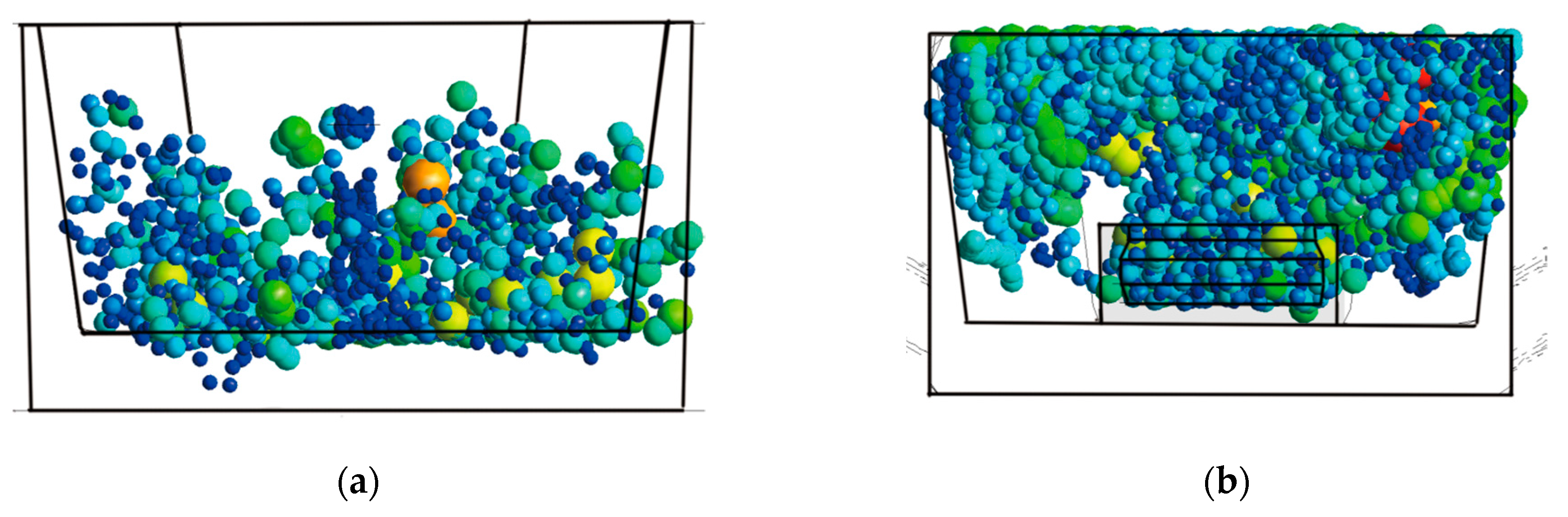
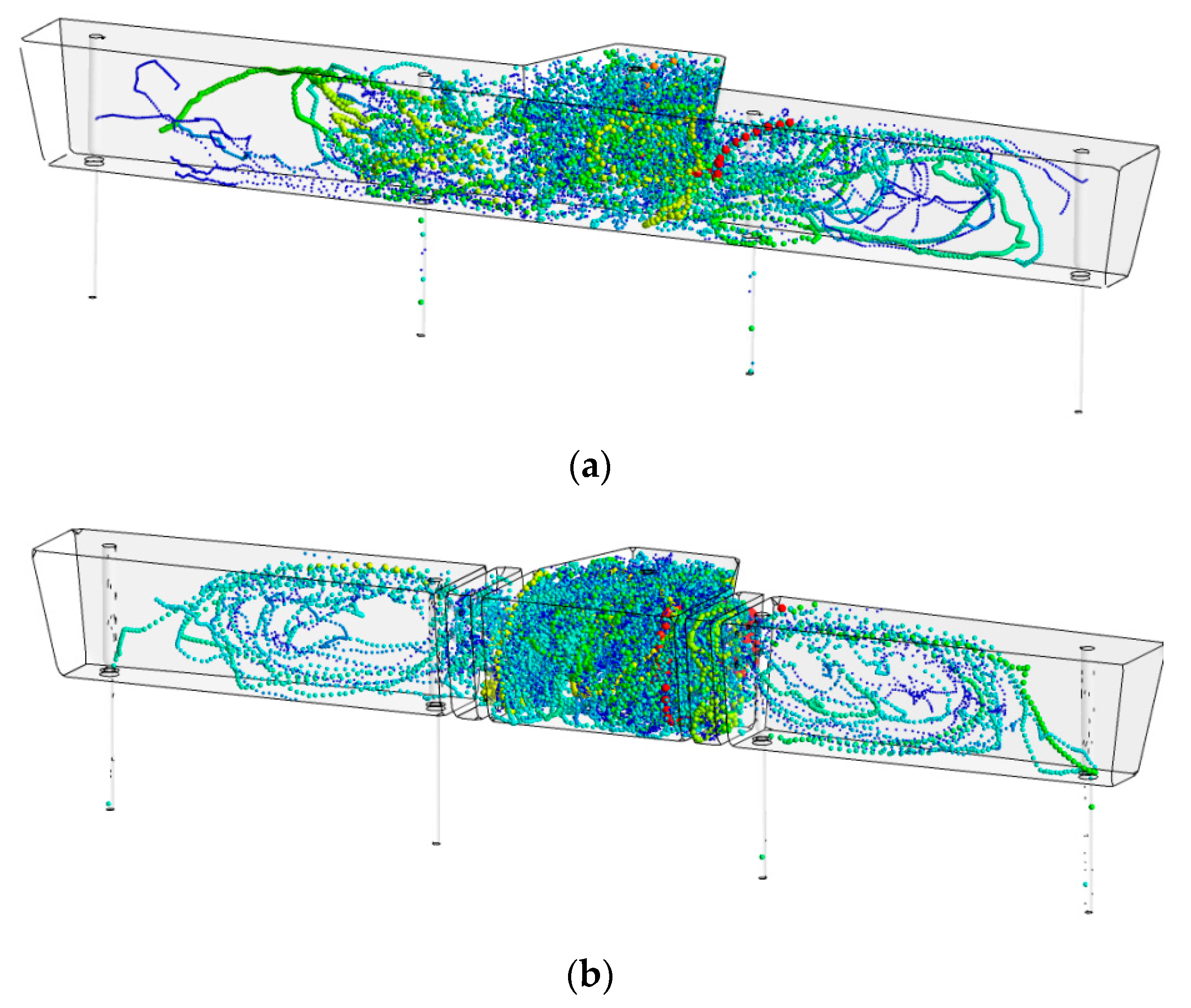
4.3. Analysis of the Influence of SCB Structure on the Removal of Fine Inclusions

Tundish is the last step of removing inclusions before molten steel is formed into cast slab. Large-size inclusions and inclusion clusters with an equivalent diameter greater than 50 μm have a great upward trend due to the influence of Stokes buoyancy, and are easily removed from molten steel. However, fine inclusions with an equivalent diameter of less than 20 μm are difficult to float to the steel slag interface due to better flowability, and eventually show a star-shaped scattered distribution in the slab, forming defects in the slab, making it difficult to obtain high-quality steel. In this paper, the change of SCB structure affects the molten steel flow field and then affects the operating state of the inclusions, increases the contact probability between the molten steel stream and the adsorbed slag layer, promotes the material exchange between the mold slag and the molten steel stream, and makes fine inclusions enter the slag layer to achieve the purpose of purifying molten steel.
The percentage of removal rate of fine inclusions under different schemes is shown in Figure 12. It can be seen from the figure that, under the optimization of the SCB structure, the removal rate of fine inclusions of all schemes is better than the removal effect of Scheme 0. The significance level of the removal effect of different schemes is compared, and the analysis results are shown in Table 5. According to the significance level of the four structural parameters, the influence of the four structural parameters on the removal rate of fine inclusions is ranked as factor D > C > B > A, where the opening diameter of the DPRW structure has a greater influence on the fine inclusions, and the significance level less than 0.05, therefore more significant.
According to the results of the orthogonal experiment, the effect of different DPRW structure opening diameters on the removal rate of fine inclusions is calculated as shown in Figure 13. The opening method with a smaller diameter allows the molten steel to obtain a higher initial velocity under the acceleration effect of the diversion hole, and can send more fine inclusions moving with the flow to the steel slag interface for removal. At the same time, the opening diameter of 50 μm can prolong the residence time of the inclusion in the cavity of the DPRW structure and obtain a higher collision probability during the movement between the two walls, thus forming particle clusters with larger equivalent diameter. Finally, under the action of Stokes buoyancy force, the particles float up and contact the steel slag interface between the retaining walls to be removed.
As shown in Figure 14, the inclusions arrive at the bottom of the T-shaped area along with the high-speed molten steel during the pouring process. The movement law of the inclusions in Scheme 0 is shown in Figure 14a. Smaller sized fine inclusions are deposited on the bottom of the tundish under the impact of the molten steel flow due to their lower buoyancy. Only the inclusions with larger equivalent diameter and the particle clusters formed by collision growth have the chance to float up, but still only a small part of them can reach the top surface of the injection zone and be adsorbed by the protective slag. When the IRS structure is the A2B1 combination, the movement of the inclusions in the T-shaped area is shown in Figure 14b. The IRS structure effectively changes the movement direction of the fine inclusions in the injection stage. After reaching the bottom of the tundish, the movement direction of the inclusions develops from the bottom surface laterally to the opposite direction of the molten steel injection. The inclusions collide with each other during the ascent to form a larger size inclusion cluster, so that a large proportion of particles can reach the steel slag interface and enter the mold slag through material exchange to achieve the purpose of purifying molten steel. The fine inclusions with a diameter of less than 10 μm also have a chance to reach the steel slag interface. When T = 15 s, a considerable part of the inclusions in the original tundish flow out of the T-shaped area under the action of the flow. The addition of the IRS structure changes the direction of the movement of the inclusions, and extends the residence time of the inclusions in the T-shaped area to 30 s.
The influence of the DPRW structure on the removal rate of fine inclusions is mainly concentrated in the outlet flow area, and the effect is shown in Figure 15. Due to the lack of blockage by the flow control device in Scheme 0, smaller inclusions develop laterally along the bottom in the injection area. The material still stays at the bottom of the tundish and follows the molten steel into the mold when it reaches the inner nozzle of the measuring nozzle, forming a billet defect. The inclusions in the original tundish that enter the outlet flow area are basically captured by the swirling flow formed at the inner outlet. There are almost no inclusions that can be close to the outer outlet, which makes the number of escaped inclusions from the inner and outer outlets different, and further deteriorates the quality of the inner outlet casting billet. After installing the DPRW structure flow control device, the movement trajectory of the fine inclusions in the tundish is shown in Figure 15b. The fine inclusions flowing out of the injection zone continuously change the direction of motion and collide with one another in the middle cavity of the DPRW structure, so that the inclusions flowing out of the cavity have almost no particles with an equivalent diameter less than 7 μm. The combination of the BITO hole opening method and the horizontal angle of 30° diversion hole causes the molten steel flowing out of the cavity to form an internal swirling flow with a large displacement path between the inner and outer outlets, which promotes the continuous movement of fine inclusions between the inner and outer outlets and the steel slag interface. On the one hand, this movement method increases the probability of inclusion particles contacting the mold powder, and on the other, it enhances the consistency of the quality of the casting slab at the inner and outer outlets.

5. Conclusions

In order to obtain better fine inclusion removal effect and flow field state in tundish, SCB structure is adopted to improve the approximate T-type four-flow tundish. Numerical simulation is used to study the influence degree of SCB structure with different structural parameters on improving the quality of molten steel, and the following results are obtained.
  • Compared with the original tundish, SCB’s flow control device combination can effectively improve the flow field operation state and increase the removal rate of fine inclusions. The flow control device makes the average residence time of molten steel extended by up to 106 s, the dead zone volume fraction is the highest decrease by 10.5%, and the dispersion of molten steel composition at the inner and outer outlets by 60.1%;
  • The change of DPRW structure parameters has a significant effect on the average residence time, the volume fraction of dead space and the removal rate of fine inclusions, while the IRS structure only has a significant effect on the change of the volume fraction of dead space. However, the IRS structure has an important influence on the direction of movement of inclusions in the injection zone and the reduction in molten steel injection velocity, which makes the average velocity in the tundish drop by 22% compared to the original package;
  • The diameter of the guide hole of the DPRW structure has the greatest influence on the change of the flow field state of the tundish, and the X-shaped opening method is most beneficial to the optimization of the flow field of the tundish. The X-shaped opening method causes the molten steel flow to form a large-area swirl and vortex in the outlet flow area of the tundish, and plans the best route for the subsequent flow field movement;
  • The larger the diameter of the guide hole in the DPRW structure, the more beneficial it is to improve the flow field, increase the average residence time, and reduce the volume fraction of the dead zone. The volume fraction of the dead zone when the diameter is enlarged by 50 mm is reduced by 3.3%. Decreasing the diameter of the diversion hole is conducive to the removal of fine inclusions, and the removal rate of inclusions is increased by 13.6% when the diameter is reduced by 50 mm, which is conducive to improving the yield of high-quality steel;
  • The trajectory of fine inclusions with a diameter of less than 20 μm is highly coincident with the flow field of the tundish. Therefore, it can be judged that the flowability is the most important factor affecting the removal rate. Changing the flow field can effectively affect the removal rate of fine inclusions. The relationship between the removal mechanism of fine inclusions and flowability needs to be studied further in the future.
In the future research work, more attention should be paid to the effect of SCB structure parameters on tundish of different structures. Caal2o4 inclusion is also an important cause of nodulation at the tundish outlet, therefore the removal effect of SCB structure on this inclusion also needs further experiments.

Author Contributions

Y.J., F.G. and Z.L. proposed and designed the project process. P.L., J.H. and J.L. conducted data collection and sorting work. Z.L. performed numerical simulations and analyzed the data. All authors have made considerable contributions to the results and discussions. Z.L. and Y.J. wrote and revised the article. All authors have read and agreed to the published version of the manuscript.

Funding

This research received no external funding.

Institutional Review Board Statement

Not applicable.

Informed Consent Statement

Not applicable.

Data Availability Statement

Publicly available datasets were analyzed in this study. This data can be found here [https://orcid.org/0000-0002-1495-8899].

Conflicts of Interest

The authors declare no conflict of interest.

References

  1. Tian, D.Y.; Zhang, J.; Bai, H.; Cang, D.Q. Numerical and physical simulation on fluid flow of a tundish of six-strand continuous casting. Energy Metall. Ind. 2018, 37, 42–47. [Google Scholar]
  2. Mazumdar, D. Tundish metallurgy:Towards increased productivity and clean steel. Trans. Indian Inst. Met. 2013, 66, 597–610. [Google Scholar] [CrossRef]
  3. Fan, J.F.; Zhang, Q.L.; Zhu, M.; Lei, H.; Wang, W.Z. Water modeling study on optimization of flow control devices in “t” type tundish of six-strand caster. Iron Steel 1998, 33, 24–28. [Google Scholar]
  4. Jin, Y.L.; Jin, Y.; Feng, X.W.; Chang, Z.S.; Luo, X.; Yuan, H.; Ye, C. Simulation study on optimization of eccentric nozzle structure for round mould. Foundry Technol. 2016, 37, 1186–1191. [Google Scholar]
  5. Qin, X.F.; Cheng, C.G.; Li, Y.; Zhang, C.M.; Zhang, J.L.; Jin, Y. A simulation study on the flow behavior of liquid steel in tundish with annular argon blowing in the upper nozzle. Metals 2019, 9, 225. [Google Scholar] [CrossRef] [Green Version]
  6. Jin, Y.; Ye, C.; Luo, X.; Yuan, H.; Cheng, C.G. The model analysis of inclusion moving in the swirl flow zone sourcing from the inner-swirl-type turbulence controller in tundish. High Temp. Mater. Process. 2017, 36, 541–550. [Google Scholar] [CrossRef]
  7. Siddiqui, M.I.H.; Jha, P.K. Numerical simulation of flow-induced wall shear stresses in three different shapes of multi-strand steelmaking tundishes. Steel Res. Int. 2015, 86, 799–807. [Google Scholar] [CrossRef]
  8. Ding, N.; Bao, Y.P.; Sun, Q.S.; Wang, L.F. Optimization of flow control devices in a single-strand slab continuous casting tundish. Int. J. Min. Met. Mater. 2011, 18, 292–296. [Google Scholar] [CrossRef]
  9. Wen, G.H.; Huang, Y.F.; Tang, P. Improvement of tundish shape and optimization of flow control devices for sequence casting heavy steel ingots. Int. J. Min. Met. Mater. 2012, 19, 15–20. [Google Scholar] [CrossRef]
  10. Wang, J.H. Development and application of long life technology to slab continuous casting tundish. Gansu Metall. 2015, 3, 20–22. [Google Scholar]
  11. Heaslip, L.J.; Mclean, A.; Sommerville, I.D. Continuous Casting: Chemical and Physical Interactions during Transfer Operations; Iron & Steel Society of AIME: Charlottesville, VA, USA, 1983; pp. 22–26. [Google Scholar]
  12. Yang, F.; Jin, Y.; Zhu, C.Y.; Dong, X.S.; Lin, P.; Cheng, C.G.; Li, Y.; Sun, L.; Pan, J.H.; Cai, Q. Physical simulation of molten steel homogenization and slag entrapment in argon blown ladle. Processes 2019, 7, 479. [Google Scholar] [CrossRef] [Green Version]
  13. Li, Y.; Wang, J.; Zhang, J.Q.; Cheng, C.G.; Zeng, Z. Deformation and structure difference of steel droplets during initial solidification. High Temp. Mater. Process. 2017, 36, 347–357. [Google Scholar] [CrossRef]
  14. Li, Y. Study on New Type Turbulence Inhibitor’s Effect on Flow Field of Steel in Tundish by Numerical and Physical Modeling. Master’s Thesis, Wuhan University of Science and Technology, Wuhan, China, 2015. [Google Scholar]
  15. Chen, J.B. Fundamentals of Numerical Simulation of Metallurgical Process; Metallurgical Industry Press: Beijing, China, 2008; p. 213. [Google Scholar]
  16. Zhang, H.; Liu, C.S.; Lin, Q.; Wang, B.; Liu, X.Q.; Fang, Q. Formation of plastic inclusions in U71Mnk high-speed heavy-rail steel refined by Cao-SiO2-Al2O3-MgO slag. Metall. Mater. Trans. B 2018, 50, 459–470. [Google Scholar] [CrossRef]
  17. Li, X.W. Study on Critical Liquid Level of Tundish Slag in Continuous Casting. Master’s Thesis, Northeastern University, Shenyang, China, 2011. [Google Scholar]
  18. Pan, J.D. Numerical Simulation of Flow Field and Structure Optimization of Molten Steel in a Three-Flow Tundish. Master’s Thesis, Yanshan University, Qinhuangdao, China, 2018. [Google Scholar]
  19. Jin, Y.; Dong, X.S.; Yang, F.; Cheng, C.G.; Li, Y.; Wang, W. Removal mechanism of microscale non-metallic inclusions in a tundish with multi-hole-double-baffles. Metals 2018, 8, 611. [Google Scholar] [CrossRef] [Green Version]
  20. Chen, Y.Q.; Wang, X.B.; Qiu, S.T.; Peng, S.H. Study on the residence time distribution characteristics of t type eight-strand continuous casting tundish. Steel Vanadium Titan. 2009, 30, 46–50. [Google Scholar]
  21. Zhao, Y. Mathematical and Physical Simulation and Optimization of Two-Stream Asymmetric Tundish Flow Control Device. Ph.D. Thesis, Northeastern University, Shenyang, China, 2012. [Google Scholar]
  22. Sahai, Y.; Emi, T. Melt flow characterization in continuous casting tundishes. ISIJ Int. 1996, 36, 667–672. [Google Scholar] [CrossRef]
  23. Bensouici, M.; Bellaouar, A.; Talbi, K. Numerical investigation of the fluid flow in continuous casting tundish using analysis of rtd curves. J. Iron Steel Res. Int. 2009, 16, 22–29. [Google Scholar] [CrossRef]
  24. Braga, B.M.; Tavares, R.P. Description of a new tundish model for treating rtd data and discussion of the communication “new insight into combined model and revised model for rtd curves in a multi-strand tundish” by lei. Metall. Mater. Trans. B 2018, 49, 2128–2132. [Google Scholar] [CrossRef]
  25. Chatterjee, S.; Asad, A.; Kratzsch, C.; Schwarze, R.; Chattopadhyay, K. Mixing and residence time distribution in an inert gas-shrouded tundish. Metall. Mater. Trans. B 2017, 48, 17–21. [Google Scholar] [CrossRef]
  26. Li, D.X.; Cui, H.; Liu, Y.; Tian, E.H.; Du, J.X. A new method based on the f-curve for characterizing fluid flow in continuous casting tundishes. Metall. Mater. Trans. B 2016, 47, 1237–1242. [Google Scholar] [CrossRef]
  27. Han, L.H.; Yu, C.M. Numerical simulation and water model study on rtd curve of tundish. Metall. Energy 2021, 40, 17–22. [Google Scholar]
  28. Lei, H.; Zhao, Y.; Bao, J.L.; Liu, C.J.; Chen, H.G.; He, J.C. Whole analysis approach for residue time distribution curve in multi-strand continuous casting tundish. Acta Metall. Sin. 2010, 46, 1109–1114. [Google Scholar] [CrossRef]
  29. Zhang, B.L.; Liu, F.H.; Zhu, R.; Zhu, J.F. Effects of multiple-hole baffle arrangements on flow fields in a five-strand asymmetric tundish. Materials 2020, 13, 5129. [Google Scholar] [CrossRef]
  30. Ling, H.; Zhang, L.; Li, H. Mathematical modeling on the growth and removal of non-metallic inclusions in the molten steel in a two-strand continuous casting tundish. Metall. Mater. Trans. B 2016, 47, 2991–3012. [Google Scholar] [CrossRef]
  31. Lopez-Ramirez, S.; Barreto, J.D.J.; Palafox-Ramos, J. Modeling study of the influence of turbulence inhibitors on the molten steel flow, tracer dispersion, and inclusion trajectories in tundishes. Metall. Mater. Trans. A 2001, 32, 615–627. [Google Scholar] [CrossRef]
  32. Yao, C.; Wang, M.; Pan, M.X.; Bao, Y.P. Optimization of large capacity six-strand tundish with flow channel for adapting situation of fewer strands casting. J. Iron Steel Res. Int. 2021, 1–11. [Google Scholar] [CrossRef]
Figure 1. Approximate T-shaped tundish geometric structure size (mm). (a) Front view; (b) left view; and (c) top view.
Metals 11 01208 g001
Figure 2. SCB mode structure chart. (a) IRS mode; (b) TIBO mode; (c) BITO mode; and (d) X mode.
Metals 11 01208 g002aMetals 11 01208 g002b
Figure 3. SCB structure location.
Metals 11 01208 g003
Figure 4. Theoretical average residence time distribution function.
Metals 11 01208 g004
Figure 5. Unstructured meshing effect diagram.
Metals 11 01208 g005
Figure 6. Calculation model establishment process.
Metals 11 01208 g006
Figure 7. Average residence time of each program.
Metals 11 01208 g007
Figure 8. Average residence time dispersion of different schemes.
Metals 11 01208 g008
Figure 9. Average residence time curve. (a) Scheme 0; (b) Scheme 7; and (c) Scheme 10.
Metals 11 01208 g009
Figure 10. Tracer concentration display. (a) Scheme 0; (b) Scheme 6; and (c) Scheme 10.
Metals 11 01208 g010
Figure 11. Speed cloud graph display. (a) Scheme 0 and (b) Scheme 10.
Metals 11 01208 g011
Figure 12. Stacked histogram of removal rate of fine inclusions.
Metals 11 01208 g012
Figure 13. Bar graph of inclusion removal rate of different retaining wall opening diameters.
Metals 11 01208 g013
Figure 14. The influence of IRS structure on the trajectory of inclusions in the T-shaped area. (a) A0B0 T = 15 s; (b) A2B1 T = 30 s.
Metals 11 01208 g014
Figure 15. The influence of DPRW structure on the trajectory of inclusions. (a) C0D0; (b) C2D1.
Metals 11 01208 g015
Table 1. SCB model structure parameters.
IRS ModeParameterDPRW ModeParameter
Angle of diversion hole/°30Angle of diversion hole/°30
Inner diameter of stabilizer/mm100Retaining wall thickness/mm90
Outer diameter of stabilizer/mm650Inner cavity thickness/mm200
Inner diameter of stop/mm220--
Outer diameter of stop/mm300--
Table 2. Orthogonal experiment combination.
LevelFactor
ABCD
145With diversion holesTIBO mode50
290No diversion holeBITO mode100
3135-X mode-
Table 3. Average residence time and dead zone volume fraction of different schemes.
Serial NumberScheme t a ( s ) Outflow 1Outflow 2
t ( s ) V p ( % ) V d ( % ) t ( s ) V p ( % ) V d ( % )
0A0B0C0D0655558 10.4619.6967525.88 13.44
1A1B1C1D1613 658 38.82 12.40 697 38.74 12.44
2A3B2C3D1614 650 39.07 11.04 698 45.82 11.66
3A3B1C2D2613 622 38.33 9.12 719 46.32 10.01
4A2B1C2D1613 627 32.46 11.14 686 42.49 11.44
5A1B2C2D1613 640 34.66 11.77 688 39.47 12.03
6A2B1C3D1613 639 41.83 10.92 691 42.24 11.14
7A1B1C3D2615 682 49.20 9.36 674 33.26 10.30
8A3B1C1D1613 647 32.46 11.94 688 39.96 12.21
9A2B2C1D2614 701 48.75 9.39 625 36.46 11.75
Table 4. Range of average residence time and dead zone volume fraction of different schemes.
ParameterAverage Residence Time (s)Dead Zone Volume Fraction (%)
ABCDABCD
K166064666964411.18 10.81 11.24 11.54
K265666463066810.48 10.73 10.68 9.29
K3640-657-10.70 -10.44 -
square error344636120212330.370.010.510.1
Significance level0.260.1490.0910.0860.0010.0160.00050.0001
Table 5. The range and variance of the removal rate of fine inclusions in different schemes.
ParameterInclusion Removal Rate (%)
ABCD
K180.41 80.81 82.65 85.75
K282.77 82.06 81.64 72.18
K380.49 -79.38 -
Mean square error5.373.168.43368.20
Significance level0.1270.1820.0850.002
Publisher’s Note: MDPI stays neutral with regard to jurisdictional claims in published maps and institutional affiliations.

