Author Contributions
Conceptualization, C.L. and X.D.; methodology, X.Y.; software, C.L.; validation, H.L., C.D. and J.W.; formal analysis, C.L.; investigation, J.W.; resources, C.D.; data curation, H.L.; writing—original draft preparation, C.L.; writing—review and editing, X.D.; visualization, X.Y.; supervision, X.D.; project administration, X.Y.; funding acquisition, X.D. All authors have read and agreed to the published version of the manuscript.
Funding
This research was funded the National Key R&D Program of China (2017YFB0603801).
Institutional Review Board Statement
Not applicable.
Informed Consent Statement
Not applicable.
Data Availability Statement
Not applicable.
Conflicts of Interest
The authors declare no conflict of interest.
Nomenclature
| As | Area (m2) | R | Molar gas constant (J/mol·K) |
| Cp | Specific heat capacity (J/kg·K) | Ri | Rate of reaction i (mol/m3·s) |
| Di | Mass diffusion coefficient (m2/s) | Re | Reynolds number (‒) |
| Dsh | Diameter of kiln (m) | Sϕ,p | Source term for phase p (kg/m3·s) |
| Ea,i | Activation energy of reaction i (J/kg·mol) | T | Temperature (K) |
| Fgs | Drag force (N/m2) | vp | Velocity of phase p (m/s) |
| Gr | Grashof number (‒) | Yi | Mole fraction of species i (‒) |
| Hp | Enthalpy of phase p (J/mol) | Greek Symbols |
| ΔHi | Enthalpy of reaction i (J/mol) | αs | Thermal diffusivity (m2/s) |
| h | Heat transfer coefficient (W/m2·K) | εp | Volume fraction of phase p (‒) |
| J | Radiation intensity (W/m2) | θ | Central angel (rad) |
| k | Turbulence kinetic energy (J) | λp | Thermal conductivity (W/m·K) |
| Ke,i | Equilibrium constant of reaction i (‒) | ρp | Density of phase p (kg/m3) |
| Mi | Molecular weight of species i (kg/mol) | σ | Stefan-Boltzmann constant (W/m2·K4) |
| P | Pressure (Pa) | Subscripts |
| Pr | Prandtl number (‒) | g | Gas phase |
| q | Heat flux (J/m2·s) | s | Solid phase |
References
- Quader, M.A.; Ahmed, S.; Dawal, S.Z.; Nukman, Y. Present needs, recent progress and future trends of energy-efficient Ultra-Low Carbon Dioxide (CO2) Steelmaking (ULCOS) program. Renew. Sustain. Energy Rev. 2016, 55, 537–549. [Google Scholar] [CrossRef]
- Xu, W.; Cao, W.; Zhu, T.; Li, Y.; Wan, B. Material Flow Analysis of CO2 Emissions from Blast Furnace and Basic Oxygen Furnace Steelmaking Systems in China. Steel Res. Int. 2015, 86, 1063. [Google Scholar] [CrossRef]
- Qu, Y.; Yang, Y.; Zou, Y.; Zeilstra, C.; Meijer, K.; Boom, R. Thermal decomposition behavior of fine ore particle. ISIJ Int. 2014, 53, 2196–2205. [Google Scholar] [CrossRef] [Green Version]
- Srivastava, B.; Roy, S.K.; Sen, P.K. An Approach for Simulation of COREX Process Smelter Gasifier for Prediction of Coal Rate and Silicon in Hot Metal. Metall. Mater. Trans. B 2010, 41, 935–939. [Google Scholar] [CrossRef]
- Wu, S.; Xu, J.; Yang, S.; Zhou, Q.; Zhang, L. Basic Characteristics of the Shaft Furnace of COREX(R) Smelting Reduction Process Based on Iron Oxides Reduction Simulation. ISIJ Int. 2010, 50, 1032–1039. [Google Scholar] [CrossRef] [Green Version]
- Liu, X.; Pan, G.; Wang, G.; Wen, Z. Mathematical model of lump coal falling in the freeboard zone of the COREX melter gasifier. Energy Fuels 2011, 25, 5729–5735. [Google Scholar] [CrossRef]
- Zhang, X.H.; Zhao, K.; Bai, G.C.; Zhang, Y.Z.; Gao, J.J.; Zhang, Y.Y. Thermal analysis of rotary kiln oxygen combustion melting furnace under multi-constraint conditions. Iron Steel 2020, 55, 9–15. [Google Scholar]
- Gao, J.J.; Wan, X.Y.; Qi, Y.H.; Wang, F. Technical analysis on ironmaking process of rotary kiln pre-reduction and smelting by coal and oxygen. J. Iron Steel Res. 2018, 30, 91–96. [Google Scholar]
- Kingsley, T.C.; Kritzinger, H.P. Modelling and optimization of a rotary kiln direct reduction process. J. South. Afr. Inst. Min. Metall. 2015, 115, 51–60. [Google Scholar]
- Mujumdar, K.S. Modeling of Rotary Cement Kilns: Applications to Reduction in Energy Consumption. Ind. Eng. Chem. Res. 2016, 45, 2315–2330. [Google Scholar] [CrossRef]
- Mujumdar, K.S.; Ranade, V.V. CFD modeling of rotary cement kilns. Asia-Pac. J. Chem. Eng. 2008, 3, 106–118. [Google Scholar] [CrossRef]
- Gaurav, G.K.; Khanam, S. Computational fluid dynamics analysis of sponge iron rotary kiln. Case Stud. Therm. Eng. 2016, 9, 14–27. [Google Scholar] [CrossRef] [Green Version]
- Gaurav, G.K.; Khanam, S. Analysis of temperature profile and % metallization in rotary kiln of sponge iron process through CFD. J. Taiwan Inst. Chem. Eng. 2016, 63, 473–481. [Google Scholar] [CrossRef]
- Manju, M.S.; Savithri, S. Three dimensional CFD simulation of pneumatic coal injection in a direct reduction rotary kiln. Fuel 2012, 102, 54–64. [Google Scholar] [CrossRef]
- Vicente, W.; Ochoa, S.; Aguillon, J.; Barrios, E. An Eulerian model for the simulation of an entrained flow coal gasifier. Appl. Therm. Eng. 2003, 23, 1993–2008. [Google Scholar] [CrossRef]
- Merrick, D. Mathematical models of the thermal decomposition of coal. Fuel 1983, 62, 540–546. [Google Scholar] [CrossRef]
- Kuwauchi, Y.; Barati, M. A Mathematical Model for Carbothermic Reduction of Dust-Carbon Composite Agglomerates. ISIJ Int. 2013, 53, 1097–1105. [Google Scholar] [CrossRef] [Green Version]
- Donskoi, E.; Mcelwain, D.L.S.; Wibberley, L.J. Estimation and modeling of parameters for direct reduction in iron ore/coal composites: Part II. Kinetic parameters. Metall. Mater. Trans. B 2003, 34, 255–266. [Google Scholar] [CrossRef]
- Magnussen, B.F.; Hjertager, B.H. On mathematical modeling of turbulent combustion with special emphasis on soot formation and combustion. Symp. Combust. 1977, 16, 719–729. [Google Scholar] [CrossRef]
- Silaen, A.; Wang, T. Effect of turbulence and devolatilization models on coal gasification simulation in an entrained-flow gasifier. Int. J. Heat Mass Transf. 2010, 53, 2074–2091. [Google Scholar] [CrossRef]
- Mei, Z.; Li, P.; Wang, F.; Zhang, J.; Mi, J. Influences of Reactant Injection Velocities on Moderate or Intense Low-Oxygen Dilution Coal Combustion. Energy Fuels 2013, 28, 369–384. [Google Scholar] [CrossRef]
- Sun, S.; Lu, W.K. Mathematical Modeling of Reactions in Iron Ore/Coal Composites. ISIJ Int. 2007, 33, 1062–1069. [Google Scholar] [CrossRef]
- Sun, S.; Lu, W.K. Building of a Mathematical Model for the Reduction of Iron Ore in Ore/Coal Composites. ISIJ Int. 2007, 39, 130–138. [Google Scholar] [CrossRef] [Green Version]
- Sun, K.; Lu, W.K. Mathematical Modeling of the Kinetics of Carbothermic Reduction of Iron Oxides in Ore-Coal Composite Pellets. Metall. Mater. Trans. B 2009, 40, 91–103. [Google Scholar] [CrossRef]
- Jones, W.P.; Launder, B.E. The prediction of laminarization with a two-equation model of turbulence. Int. J. Heat Mass Transf. 1972, 15, 301–314. [Google Scholar] [CrossRef]
- Jaw, Y.; Chen, C. Fundamentals of turbulence modeling. J. Fluid Mech. 1998, 371, 379–381. [Google Scholar]
- Chui, E.H.; Raithby, G.D. Computation of radiant heat transfer on a nonorthogonal mesh using the finite-volume method. Numer. Heat Transf. Part B Fundam. 1993, 23, 269–288. [Google Scholar] [CrossRef]
- Smith, T.F.; Shen, Z.F.; Friedman, J.N. Evaluation of coefficients for the weighted sum of gray gases model. ASME J. Heat Transf. 1982, 104, 602–608. [Google Scholar] [CrossRef]
- Gorog, J.P.; Adams, T.N.; Brimacombe, J.K. Regenerative heat transfer in rotary kilns. Metall. Trans. B 1982, 13, 153–163. [Google Scholar] [CrossRef]
- Tscheng, S.H.; Watkinson, A.P. Convective heat transfer in a rotary kiln. Can. J. Chem. Eng. 1979, 57, 433–443. [Google Scholar] [CrossRef] [Green Version]
- Marias, F.; Roustan, H.; Pichat, A. Modelling of a rotary kiln for the pyrolysis of aluminium waste. Chem. Eng. Sci. 2005, 60, 4609–4622. [Google Scholar] [CrossRef]
- Boateng, A.A. On flow-induced kinetic diffusion and rotary kiln bed burden heat transport. Chem. Eng. Commun. 1998, 170, 51–66. [Google Scholar] [CrossRef]
- Boateng, A.A.; Barr, P.V. A thermal model for the rotary kiln including heat transfer within the bed. Int. J. Heat Mass Transf. 1996, 39, 2131–2143. [Google Scholar] [CrossRef]
- Agrawal, A.; Ghoshdastidar, P.S. Numerical simulation of heat transfer during production of rutile titanium dioxide in a rotary kiln. Int. J. Heat Mass Transf. 2017, 106, 263–279. [Google Scholar] [CrossRef]
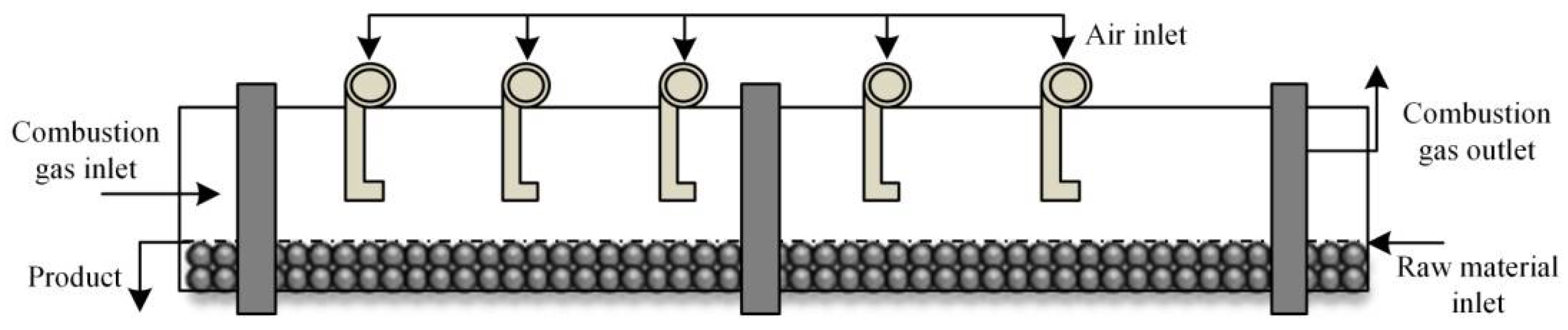
Figure 1.
Schematic diagram of the pre-reduction rotary kiln.
Figure 2.
Heat and mass transfer between freeboard region and bed region.
Figure 3.
Simplified geometric model of the rotary kiln.
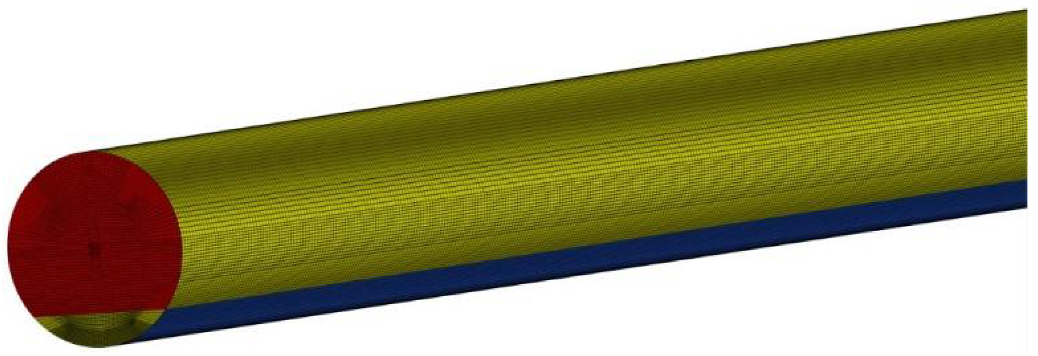
Figure 4.
Computation mesh.
Figure 5.
Temperature distribution of the gas phase along the axial section.
Figure 6.
Temperature distribution of the solid phase within the bed cross-section.
Figure 7.
Temperature distribution of the cross-section along the axis of the rotary kiln.
Figure 8.
Composition distributions of the gas phase along the axial section.
Figure 9.
Average mole fraction of gas composition in the bed region along the axial section.
Figure 10.
Average mass fraction of solid composition in the bed region along the axial section.
Figure 11.
Average bed temperature along the axial section for different C/O mole ratios.
Figure 12.
Reduction potential along the axial section for different C/O mole ratios.
Figure 13.
Metallization rate along the axial section for different C/O mole ratio.
Figure 14.
Average bed temperature along the axial section for different fill degrees.
Figure 15.
Reduction potential along the axial section for different fill degree.
Figure 16.
Metallization rate along the axial section for different fill degrees.
Table 1.
Variables in Equation (1).
| Phase | Eq. | ϕ | Γϕ | Sϕ |
|---|
| Gas | Mass | 1 | 0 | Sϕ,g |
| Momentum | | 0 | |
| Energy | Hg | λg/CP,g | |
| Species i | Yi,g | ρg Di | |
| Solid | Mass | 1 | 0 | Sϕ,s |
| Momentum | | 0 | |
| Energy | Hs | λs,eff/CP,s | |
| Species j | Yj,s | ρsDj | |
Table 2.
Kinetic parameters of homogenous reactions [
20,
21].
| Reaction | Ar (s−1) | Ea (J/kmol) | βr | Reaction Order |
|---|
| 2CO + O2 = 2CO2 | 2.2 × 10¹² | 1.7 × 10⁸ | 0 | [CO][O2] |
| 2H2 + O2 = 2H2O | 6.8 × 10¹⁵ | 1.67 × 10⁸ | −1 | [H2]0.25[O2]1.5 |
| CO + H2O = CO2 + H2 | 2.75 × 10⁹ | 8.4 × 10⁷ | 0 | [CO][H2O] |
Table 3.
Kinetic parameters of heterogeneous reactions [
24].
| Reactions | ki,0 (m·s−1) | Ea (J/mol) | Ke | Rate Expressions |
|---|
| C + CO2 = 2CO | 1.87 × 10⁸ | 221,800 | exp (−20,765.92/T + 32.8) | Equation (9) |
| C + H2O = CO + H2 | 6.05 × 10⁵ | 172,700 | exp (−16,142.19/T + 28.16) | Equation (10) |
| 3Fe2O3 + CO = 2Fe3O4 + CO2 | 2700 | 113,859 | exp (5815.5/T + 5.5076) | Equation (7) |
| 3Fe2O3 + H2 = 2Fe3O4 + H2O | 160 | 92,000 | exp (2065/T + 8.102) | Equation (8) |
| Fe3O4 + CO = 3FeO + CO2 | 23 | 71,100 | exp (−4685.22/T + 5.19) | Equation (7) |
| Fe3O4 + H2 = 3FeO + H2O | 30 | 63,600 | exp (−1857.51 + 1.01) | Equation (8) |
| FeO + CO = Fe + CO2 | 17 | 69,454 | exp (2376.46/T−2.82) | Equation (7) |
| FeO + H2 = Fe + H2O | 30 | 63,600 | exp (−1857.51/T + 1.01) | Equation (8) |
Table 4.
Chemical composition of fuel gas.
| Species | CO | CO2 | H2 | H2O | N2 |
|---|
| Mole fraction | 56.7 | 20.0 | 14.3 | 4.8 | 4.2 |
Table 5.
Chemical composition of raw material.
| Species | Fe2O3 | FeO | Al2O3 | SiO2 | CaO | MgO | TiO2 | C | Vol | Ash |
|---|
| Mass fraction | 38.6 | 24.6 | 2.6 | 3.5 | 1.1 | 2.7 | 5.0 | 15.3 | 4.7 | 1.9 |
Table 6.
Comparison between measured and simulated results.
| Parameters | Measured | Simulated | Relative Error |
|---|
| CO(%) | 19.4 | 20.2 | 4.3% |
| CO2(%) | 24.2 | 22.9 | 5.1% |
| H2(%) | 8.1 | 9.0 | 10.8% |
| H2O(%) | 15.2 | 14.9 | 1.6% |
| T(K) | 1023 | 1002 | 2.1% |
| Metal(%) | 70.0 | 72.4 | 3.4% |
| Publisher’s Note: MDPI stays neutral with regard to jurisdictional claims in published maps and institutional affiliations. |
© 2021 by the authors. Licensee MDPI, Basel, Switzerland. This article is an open access article distributed under the terms and conditions of the Creative Commons Attribution (CC BY) license (https://creativecommons.org/licenses/by/4.0/).


