Article

Effects of Hot Isostatic Pressing and Heat Treatment on the Microstructure and Mechanical Properties of Cast TiAl Alloy

1
State Key Laboratory of Materials Processing and Die and Mould Technology, Huazhong University of Science and Technology, Wuhan 430074, China
2
Cast Titanium Alloy R&D Center, Beijing Institute of Aeronautical Materials, Beijing 100095, China
3
Beijing Engineering Research Center of Advanced Titanium Alloy Precision Forming Technology, Beijing 100095, China
4
Beijing Institute of Aeronautical Materials Co., Ltd., Beijing 100094, China
5
State Key Laboratory for Advanced Metals and Materials, Beijing 100083, China
6
Key Laboratory of Metallurgical Equipment and Control Technology, Wuhan University of Science and Technology, Wuhan 430081, China
*
Authors to whom correspondence should be addressed.
Metals 2021, 11(8), 1156; https://doi.org/10.3390/met11081156
Submission received: 15 June 2021 / Revised: 17 July 2021 / Accepted: 19 July 2021 / Published: 21 July 2021
(This article belongs to the Section Metal Casting, Forming and Heat Treatment)

Abstract

:
Hot isostatic pressing (HIP) and subsequent heat-treatments (HT) are necessary for titanium aluminide (TiAl) casting components. But there are few studies carefully comparing the microstructure changes from the initial as-cast condition to the final heat-treated condition. In this study, the microstructures of Ti-47Al-2Cr-2Nb (at%) alloy in the as-cast, as-HIPed and as-heat-treated conditions were characterized by optical microscopy and scanning electron microscopy. The mechanical properties after HTs were determined by the tensile tests at 700 °C. The results show that after HIP and HTs, all the microstructures exhibit a nearly lamellar (NL) structure and can be divided into an edge region and a central area. The microstructure after HIP in the edge region is normal, while distorted lamellae and many fine recrystallized grains exist in the central area. The yield strengths after three HTs are nearly the same, but the elongation after the HT at 1310 °C is much more than that after HTs at 1185 °C and 1280 °C. A refinement of colony size induced by distorted lamellae in as-HIPed condition is considered responsible for the great improvement in elongation.

1. Introduction

Titanium aluminide (TiAl)-based alloys possess low density, relatively high specific strength and good resistance to oxidation at elevated temperatures [1,2,3,4]. Due to these excellent properties, the TiAl alloys can replace the traditional Ni-based superalloys in the service temperature range from 650 °C to 1000 °C. In this case, numerous research activities were conducted all over the world, starting from the 1980s and 1990s, to understand the complex phase transformations and associated processing challenges involved with the TiAl-based alloys [5,6,7,8,9,10,11,12]. In 2011, the Ti-48Al-2Cr-2Nb alloy (at%, the unit of alloy composition is in atom percentage without any special explanation in this paper), referred to as the 4822 alloy, was introduced into service by the General Electric (GE) company in the commercial aircraft engines as a new lightweight low-pressure turbine (LPT) blade material [13,14].
TiAl casting components generally have some casting defects such as shrinkage porosities and gas holes, coarse grain size and segregation immediately after solidification [15,16]. For eliminating the casting defects and regulating the microstructure, the HIP and subsequent HT are necessary. The HIP commonly employed not only removes the shrinkage porosities, but also begins to homogenize the as-cast microstructures. An additional homogenization treatment in the α2 + γ, α + γ or α phase field may be needed, depending on the casting piece size, solidification rate and the final microstructure of interest [17]. GE has published several patents concerning the method of processing titanium aluminide alloys, especially for the 4822 alloy. A method of HT-HIP-HT was first reported in 1997 [18]. Then in 2001 and 2013, another two methods including the HIP and HT were published [19,20]. The HT before HIP in the first method is a pretreatment to stabilize the metastable microstructure of the TiAl alloys. The HIP and post-HIP HT in all three patents are used to eliminate the casting defects and obtain an appropriate microstructure, respectively. The HIP process is most commonly performed at a pressure of 172 MPa and a temperature of 1260 °C for 4 h. The subsequent HTs are commonly conducted in the α + γ two phase field to obtain a duplex (DP) structure with the equiaxed γ grains exceeding 30% by volume fraction (vol%). Many researchers have used the methods published by GE to consolidate the TiAl alloys and regulate their microstructures, and further studied the effects of different microstructures on mechanical properties [21,22,23,24,25,26]. Harding et al. reported that the 4822 alloy experienced a HT-HIP-HT process and had a fine DP microstructure with a mean γ grain size of~70 μm and roughly 6 vol% of the smaller lamellar colonies. [25] Seo et al. reported that the HIPed + heat-treated Ti-45Al-2Mn-2Nb + 0.8 vol% TiB2 alloy had a very fine DP microstructure with a homogeneous distribution of 10–50 μm equiaxed and 20–100 μm lamellar grains. Usually, most researchers pay close attention to the final microstructures and do not care about the as-HIPed microstructures. They have not compared carefully the microstructure of the as-cast, cast + HIPed and cast + HIPed + heat-treated specimens. The final microstructure may be influenced by the microstructure in the as-cast and HIPed conditions. Jeon et al. [27] studied the morphological features of an as-HIPed Ti-45Al-2Mn-2Nb + 0.8 vol% TiB2 alloy. The results showed that a typical fully lamellar structure (FL) observed in the edge region and a DP structure consisting of the equiaxed grains and lamellar colonies in the central area. In addition, the imaging area is generally limited in a specific position, such as in Gao’s study [21], which can’t well represent the features of the total microstructure. Charpentier et al. [28] showed that the macrostructure of 4822 alloy in the as-HIPed condition exhibited columnar and equiaxed zones.
In this paper, the effects of HIP and HT on the microstructure and mechanical properties of Ti-47Al-2Cr-2Nb alloy (referred to as the 4722 alloy) is investigated. Microstructures in the as-cast, as-HIPed and heat-treated conditions are compared carefully. Simultaneously, microstructures in the regions from the edge to center are characterized in detail. Corresponding tensile tests are performed at 700 °C.

2. Materials and Methods

A TiAl ingot with the nominal composition of Ti-47Al-2Cr-2Nb was first prepared by vacuum arc melting, then vacuum induction remelting and finally vacuum arc remelting. Then the ingot was placed into a vacuum arc furnace for remelting and poured into an Y2O3 coated ceramic mold preheated to 800 °C. The as-cast cylindrical bars with a diameter of 18 mm and a length of 160 mm were obtained after solidification, and a HIP process was performed at a pressure of 172 MPa and a temperature of 1260 °C for 4 h. The chemical composition of the alloy was given in Table 1. The Al, Nb and Cr contents were determined using spectrometric analysis. The O content was detected using the infrared absorption spectrometry. X-ray analysis was used to inspect the casting defects such as shrinkage porosities and inclusion particles in the as-cast bars.
Groups of HTs were applied to the as-HIPed bars and the details were shown in Table 2. The bars were heated to 1185 °C, 1280 °C and 1310 °C (in the α + γ two phase field) respectively with a heating rate of 20 °C⋅min−1. Then they were isothermally held at the above three temperatures for 4 to 6 h, followed by furnace cooling (FC) to the room temperature.
Electro discharge machining (EDM) was used to section the as-cast, as-HIPed and heat-treated bars in the transverse direction. The sectioned bar samples with a diameter of 18 mm and a length of 8 mm were carefully ground and polished for macrostructure and microstructure characterization. The polished surface was etched in a solution (HF:HNO3:H2O = 3:5:92, vol%) in order to observe macrostructures and microstructures using an optical microscope (OM). Furthermore, the microstructures and fracture morphologies were characterized using a scanning electron microscope (SEM) equipped with a secondary electron (SE) and a back-scattered electron (BSE) detector. The OM images at lower magnification were used to measure the microstructural parameters. The grain size was measured by an intercept method. The volume fraction of each phase was represented by the average area fraction.
The tensile samples were taken out of the heat-treated bars in the central area, which had the same axes with the heat-treated bars. They have a gauge length of 35 mm and diameter of 5 mm, while the total length is 71 mm and diameter of the holding end is 12 mm. The tensile tests at 700 °C were carried out on a 3382 universal testing system (Instron, Boston, MA, USA) at a strain rate of 10−4⋅s−1. The ductility was measured using extensometers clipped to the gauge length and the ductility reported referred to plastic elongation since the elastic strain was subtracted from the extensometer readings. The tensile samples were placed into a muffle furnace and heated to 700 °C with a heating rate of 20 °C⋅min−1. Then they were isothermally held at 700 °C for 5 min before loading. Three samples were tested for each HT bar and the average of the two closest values for each tensile performance parameter was calculated.

3. Results

3.1. Microstructure Characterization

3.1.1. Microstructure of As-Cast Bar

Figure 1 shows the initial as-cast structure of the 4722 alloy. Figure 1a is an optical macrograph of a transverse section of the as-cast bar. Shrinkage porosity was found in the sample. X-ray inspection indicates that these shrinkage porosities are mainly distributed in the central area of the as-cast bars, as shown in Figure 2. Most of the porosities have the size in the range of 30–80 μm. The maximum size of the shrinkage porosity was ~2.4 mm in the middle bar. But the number of this large-size porosity is only one or two. During solidification, the phase transformations occur in the 4722 alloy, which can be expressed as L → L + β → L + α → α → α + γ → α2 + γ. When the 4722 alloy is cooled to the temperature below α transus, a diffusion-controlled precipitation of γ-TiAl lamellae with L10 structure from α-phase happens. The precipitation of γ-TiAl lamellae obeys the Blackburn orientation relationship {0001}α//{111}γ and <11 2 ¯ 0>α//<110>γ, resulting in an α/γ lamellar structure. At room temperature α is present as ordered phase α2-Ti3Al with a D019 structure. As shown in Figure 1b,c, a FL structure can be observed. The FL structure consists of many lamellar colonies exhibiting a columnar morphology with the size range of 439–689 μm. Figure 1d is a SEM-BSE micrograph, in which α2 and γ phase lamellae with the gray and black contrast, respectively, are alternately arranged in the colonies. In addition, a small volume fraction of B2 phase with a white contrast is retained at colony boundaries, as shown by the white arrow.
Some γ lamellae were observed to coarsen discontinuously at the colony boundaries and extended to the adjacent colonies. These coarsened lamellae have the same orientation as those of the primary lamellae in the left colony [29], as shown by the black arrow. Jung et al. [30] found that the discontinuous coarsening dominates near the eutectoid temperature, while the continuous coarsening is observed at temperatures higher than the eutectoid temperature. However, Denquin′s study indicated that the discontinuous reaction starts even during the formation of the primary lamellar structure leading to the formation of serrated grain boundaries [31]. He found that when the Ti54Al46 alloy was cooled down from the α phase-field (1400 °C) to the α + γ phase-field (1250 °C) and oil quenched, the discontinuous precipitations including both the phases α2 and γ were observed in some areas of the grain boundaries. The discontinuous coarsening seen in this study is consistent with Denquin’s study results.

3.1.2. Morphological Features of as-HIPed Structure

Figure 3 shows the results of casting defect inspection in the 4722 alloy bars by X-ray after the HIP process. After HIP, the shrinkage porosities are effectively eliminated and the consolidated bars are obtained.
Figure 4 shows the typical as-HIPed structures of the middle bar in Figure 3. It is found that the central area has a quite different microstructure from the edge region. Therefore, the macrostructure is divided into two different regions, namely the edge region and the central area respectively, as shown in Figure 4a. Figure 4b,c show the NL structure in the edge region and central area. It can be observed that the distribution of equiaxed γ grains in the edge region and central area are different. The equiaxed γ grains are precipitated at colony boundaries in the edge region while they are precipitated at the colony boundaries and inside the colonies in the central area. The mean size of the equiaxed γ grains in the edge region is ~33 μm, while the equiaxed γ grains in the central area have a mean size of ~8.5 μm, but the volume fraction of the equiaxed γ grains in the central area is more than that in the edge region. Besides, the lamellae in the edge region are straight while the lamellae in the central area become distorted.
Figure 4d shows the microstructure in the central area. It can be observed that the fine equiaxed grains clustered at the colony boundaries and inside the colonies include not only γ grains with the black contrast, but also α2 phase with the gray contrast. This α2 phase is mainly distributed at the fine γ grain boundaries. The deformation of lamellae is not uniform, which results in the different curvatures at different position of the lamellae. At slightly deformed position, the curvature is smaller. At severely deformed position, the curvature is bigger. This may have some influences on the microstructures after the subsequent HTs.

3.1.3. Morphological Features of Heat-Treated Structure

Figure 5, Figure 6 and Figure 7 show the structures of the 4722 alloy after the three HTs. The heat-treated macrostructures are also divided into the edge region and the central area, similar to the as-HIPed macrostructure. As shown in Figure 5a, Figure 6a and Figure 7a, the diameter (D) of the central area after HT1, HT2 and HT3 was measured ~7.5 mm, ~7.1 mm and ~9.2 mm, respectively. This means that the gauge diameter of 5 mm is included in the central area. The morphological features of the three heat-treated bars are analyzed in detail as follows. The microstructural parameters of the edge region and central area are summarized in Table 3. The relative lamellar spacing range after different HTs can be statistically evaluated by the SEM-BSE.
Figure 5b,c show the microstructures of the 4722 alloy after HT1. The volume fraction of γ grains in the edge region is more than that in the central area, which are ~25.8% and ~14.4% respectively. Although the volume fraction of the γ grains is up to ~25.8%, the microstructure in the edge region is still a NL structure. And the microstructure in the central area is also a NL structure. Figure 5d shows the SEM-BSE microstructure in the central area. It can be observed that the distorted lamellae shown in Figure 4c,d become straight. Unfortunately, the α2 lamellae are discontinuous. The α2 lamellae partly dissolved and transformed to γ phase. These degenerated lamellae are harmful to the mechanical properties of the 4722 alloy. The mean interlamellar spacing is 2–4 μm.
Figure 6b,c show the microstructures of the 4722 alloy after HT2. Similarly, the microstructure is also a NL structure compared with the microstructure shown in Figure 5b. However, the volume fraction of γ grains is lower, ~17.9% and ~9.3% in the edge region and central area respectively. The SEM-BSE microstructure in the central area after HT2 shown in Figure 6d is also similar to that shown in Figure 5d. The straight lamellae and partly dissolved α2 lamellae were observed. But the amount of the dissolved α2 lamellae is apparently fewer than that in Figure 5d. The mean interlamellar spacing is 2–4 μm.
Figure 7b,c show the microstructures of the 4722 alloy after HT3. Compared with the microstructure shown in Figure 6b, the volume fraction of γ grains in the edge region is further reduced, just ~9.1%. Thus, the microstructure in the edge region is also a NL structure. Similar to the microstructure in the central area shown in Figure 6c, the microstructure in the central area in Figure 7c also exhibits a NL structure in which the volume fraction of γ grains is ~4.1%. The SEM-BSE microstructure is shown in Figure 7d. Different from the situation in Figure 5d and Figure 6d, the α2 lamellae are quite continuous and nearly no α2 lamellae are dissolved after HT3. The mean interlamellar spacing is 1–3 μm.
Table 3 lists the microstructural parameters after the three HTs in detail. As the HT temperature drops from 1310 °C to 1185 °C, the colony size in the edge region decreases gradually. But the decrease is extremely limited, just ~8%. In the central area, the colony size after heat-treated at 1280 °C and 1185 °C is gradually decreasing. However, the colony size after heat-treated at 1310 °C is obviously smaller than after heat-treated at 1280 °C and 1185 °C. This abnormal situation requires in-depth analysis. As the HT temperature decreases, the volume fraction of the equiaxed γ grains in the whole microstructure gradually increases. Additionally, the relatively interlamellar spacings after different HTs can be statistically evaluated by the SEM-BSE micrographs with a high magnification. According to the phase equilibrium, increasing the temperature can promote the γ → α transformation. The higher the HT temperature, the more α lamellae are precipitated from the γ phase. In view of this point, the interlamellar spacing has the decreasing trend with increasing the HT temperature from 1185 °C to 1310 °C.

3.2. Mechanical Properties

Figure 8 shows the tensile curves at 700 °C. Figure 9 shows the tensile properties of the 4722 alloy tested at 700 °C. The yield strength of the three heat-treated bars remains nearly the same, ~340 MPa. However, it is a different case for the ultimate tensile strength and elongation. After HT1, HT2 and HT3, the ultimate tensile strength is 433 MPa, 424 MPa and 486 MPa while the elongation is ~1.68%, ~1.34% and ~4.25%, respectively.
Figure 10 shows the fracture morphologies of the heat-treated samples after the tensile tests at 700 °C. The fracture morphologies are basically similar, exhibiting a typical brittle fracture. The crack initiated at the edge of the sample. It propagated along the lamella firstly and then propagated through the lamella as shown in Figure 10a,c. The higher magnification images inserted in Figure 10a,c show the regions near the crack initiation sites, respectively. No defects can be observed in the regions near the crack initiation sites. The translamellar, interlamellar, and inter-γ grain cracking zones are observed in Figure 10b. Figure 10d shows the fracture morphology of the sample experienced HT3, and the kinks located between the adjacent straight lamellar fragments are indicated by the red lines. The inter-γ grain cracking is easy to be observed in the HT1 fracture morphology. However, it is difficult to find the inter-γ grain cracking in the HT3 fracture morphology. This can be attributed to the volume fraction of the γ grain after HT1 is much more than that after HT3. Secondary microcracks are identified at the α2/γ lamellar interfaces. Muñoz-Moreno et al. [32,33,34,35] found that this interlamellar cracking seems to be activated above a threshold stress for a NL Ti-45Al-2Nb-2Mn-0.8vol%TiB2 alloy through the in situ tensile experiment at high temperature.

4. Discussion

4.1. Recrystallization during HIP

The shrinkage porosities in the as-cast bars are generally considered to be eliminated by the creep-diffusion mechanism. Therefore, the as-cast bars suffer plastic deformation and the strain energy is stored in the deformed region due to the collapse of the shrinkage porosities during the HIP process. Because the shrinkage porosities are mainly distributed in the central area as shown in Figure 2, the amount of plastic deformation in this area is thought to be more than that in the edge region. The strain energy stored during the HIP process was expected to be more in the central area. In this case, the lamellae in the central area become distorted while the lamellae in the edge region are still straight. Simultaneously, the lamellae near the porosity will recrystallize since they have enough strain energy to satisfy the recrystallization condition. The recrystallized phases are the α and γ phases because the HIP temperature is located in the α + γ two phase field. These phases are believed to grow as equiaxed grains during the isothermally holding process. When the bars are cooled to room temperature, γ grains grow further through the transformation from α to γ and the disorder-order transition from α to α2 occurs. Thus, a microstructure composed of the distorted lamellae and the fine grains was observed in the central area.

4.2. The Effect of HT Temperatures on the Microstructural Parameters

The lamellar structure of the 4722 alloy after the HIP process is stable, and subsequent HTs in the α + γ two phase field can’t destroy the coarse columnar lamellar colonies. The HIP process not only removes the shrinkage porosities, but also begins to homogenize the as-cast microstructure. Thus, some equiaxed γ grains were observed to precipitate at colony boundaries. The as-HIPed material has been heat-treated at 1200 °C for 20 h followed by FC and these two microstructures were compared. It is found that the coarse columnar lamellar colonies are still not destroyed as shown in Figure 5b, Figure 6b and Figure 7b, and the HT just improves the volume fraction of the equiaxed γ grains. In this case, the microstructural type does not change after the three HTs, all exhibiting a NL structure.
There are many studies in the literature about refining the microstructure of γ-TiAl alloys. Normally, wrought γ-TiAl alloys exhibit a fine-grained microstructure that can be altered over a wide range by heat-treatments [36]. Kim’s [37] study indicated that forged γ-TiAl heat-treated in the middle of the α + γ region followed by cooling to room temperature resulted in the evolution of a DP microstructure composed of the equiaxed γ grains and γ/α2 colonies. This DP microstructure has a very fined grain size of about 10–40 μm. In previous studies, the grain refinement for the as-cast γ-TiAl alloys was performed by supertransus processing or thermomechanical treatments such as canned forging or hot extrusion. Wang et al. [38] reported an alternative method by which a coarse FL structure of ~500 μm can be refined to a fine one of ~10 μm merely by rapid heat-treatment which contains 8 times of oil cooling after isothermally holding at above α transus. It is quite clear that this refinement is attributed to the high nucleation energy produced by the massive transformation, which provides the structural defects such as the dislocations and stacking faults for the subsequent transformation. Unfortunately, this method can’t be applied to the engineering of γ-TiAl alloys due to its high cooling rate.
In our study, FC is used after isothermally holding in the α + γ phase field. But even though decreasing the HT temperature to 1185 °C, the volume fraction of the γ grains can only reach ~25.8%, which can’t form a DP structure. Compared with the original as-cast colony size, the colony size in the edge region after HTs can be just refined slightly. On the other hand, these γ grains mainly precipitate at colony boundaries and seldom precipitate inside the colonies. The coarse columnar colonies can’t be divided into a number of parts due to the very few γ grains precipitated inside the colonies. In these conditions, the colony size after HTs was refined slightly. This refinement is closely related to the volume fraction of the γ grains precipitated at colony boundaries. The γ grains nucleating at colony boundaries extend to the adjacent colonies and occupy some volume of the colonies. In this way, the mean colony size is reduced. This refinement is quite limited. According to the lever rule, the volume fraction of the γ grains is gradually increasing with the HT temperature decreasing. Thus, the colony size is gradually decreasing with decreasing the HT temperature.
The microstructure in as-cast condition is not stable due to the high cooling rate. The HIP process not only removes the shrinkage porosity, but also begins to homogenize the as-cast microstructure. The subsequent HT continues to stabilize the microstructure. When the HT temperature was 1185 °C, the γ grains were precipitated by α → γ transformation due to a high γ phase content at this temperature. These γ grains were precipitated not only at colony boundaries but also in the Al-rich region due to a larger chemical free energy driving force provided by Al element. In this case, some α2 lamellae were partly dissolved and became discontinuous. When the HT temperature increases from 1185 °C to 1310 °C, the diffusivity of Al element is sufficient and the α phase content is high. The segregation of Al element can be eliminated nearly completely. Therefore, the lamellae were continuous.

4.3. The Refinement of Colony Grains by Shrinkage Porosities

The colony size in the central area should be affected not only by the HT temperature but also by the amount of shrinkage porosity in the as-cast bar. In this study, HT1 and HT2 are applied to the top and bottom bars shown in Figure 2 respectively, while HT3 is applied to the middle bar. Obviously, the amount of shrinkage porosity in the middle bar is much more than in the top and bottom bars. This will make a great difference in the colony size after HTs. X-ray inspection indicated that the shrinkage porosities were mainly present in the central area. After the HIP process, these shrinkage porosities were eliminated.
The microstructure in the central area is composed of the distorted lamellae and fine recrystallized grains, as shown in Figure 4d. For the distorted lamellae, those lamellar fragments having a smaller curvature (as shown by blue arrow) were easily recovered and became straight after the subsequent HT in the α + γ phase field, while the rest of lamellar fragments having a bigger curvature weren’t recovered. In this case, a kink is located between the adjacent straight lamellar fragments. It seems that one colony can be decomposed to two or more colonies. And the colony size is refined to some degree. The colony size after HT3 is ~243 μm, decreasing ~30% compared with the colony size after HT1 and HT2. Compared with the HT1 and HT2 bars, the HT3 bar has more porosities in the as-cast condition. In other words, the HT3 bar has more distorted lamellae after the HIP process. More distorted lamellae mean greater refinement after the HT, which is induced by the kink between adjacent straight lamellar fragments. Thus, the colony size after HT3 is apparently smaller than that after HT1 and HT2.
The fine recrystallized grains are mainly composed of γ phase. According to the phase equilibrium, increasing the temperature can promote the γ → α transformation. The higher the HT temperature, the more α lamellae are precipitated from γ grains. At the HT3 temperature, most of the recrystallized γ grains were consumed by the colonies and the residual grew into larger γ grains. This means that more volume fraction of lamellar colonies and smaller volume fraction of γ grains are in the microstructure after HT3 compared with HT1 and HT2.

4.4. The effect of Colony Size on Mechanical Properties

Compared with the commercial DP 4822 alloy [17], the yield strength at 700 °C increases ~50 MPa, while the elongation of ~4.25% after HT3 is significantly reduced by ~50%. Compared with the elongation after HT1 and HT2, the elongation after HT3 has a significant improvement, nearly 2.5 times that after HT1 and HT2. Microcracks, which nucleated and propagated along α2/γ lamellar boundaries, are mainly due to the lattice stress distribution in these two phases, that is, the lattice strains in γ phase are tensile strains, and those in α2 phase are compressive strains [39].
As presented in Figure 10, colony boundaries appear to be quite effective at stopping the propagation of microcracks. The final fracture is controlled by the propagation of these microcracks. Due to smaller colony size after HT3, the colony boundary area becomes larger, which can stop the propagation of microcracks more effectively. It has been already reported for γ-TiAl alloys that the tensile elongation at room and elevated temperatures increases with decreasing the colony size [40]. It is well known that the γ grains present at colony boundaries can partially relieve the stress concentration caused by the inconsistent deformation, thereby increasing the elongation of the alloys. From this perspective, the elongation after HT1 should be higher than that after HT3 since the volume fraction of the γ grains after HT1 is much more than that after HT3. But the mean grain size of the whole microstructure after HT3 including the colonies and γ grains after HT3 reduces by 20% compared with that after HT1. Therefore, we speculate that the significant improvement of the elongation after HT3 should be mainly attributed to the refinement of the mean grain size in the central area. In addition, the more continuous lamellae existing in the colonies and the relative smaller interlamellar spacing after HT3 should make some differences. But this special refinement seems to have no effect on the yield strength.
Additionally, it appears that the tensile stress versus strain curve for each HT sample is nearly the same until the final fracture occurs as shown in Figure 8. Perhaps the premature failure for the HT1 and HT2 samples should be attributed to the defects in the materials. For example, the HT3 material may have a smaller flaw size and lower flaw distribution compared with the HT1 and HT2 materials. Unfortunately, we did not observe the defects, such as the porosity or inclusion, existing in the region near the crack initiation site, as shown in the higher magnification images inserted in Figure 10a,c.

5. Conclusions

In the present work, the effects of HIP and HT on microstructure and mechanical properties of cast Ti-47Al-2Cr-2Nb alloy were studied. The following conclusions can be drawn from this work:
(1)
The microstructure after HIP can be divided into two different regions. In the edge region, the microstructure exhibits a normal NL structure, but in the central area, the microstructure consists of deformed lamellae and a great number of fine recrystallized grains.
(2)
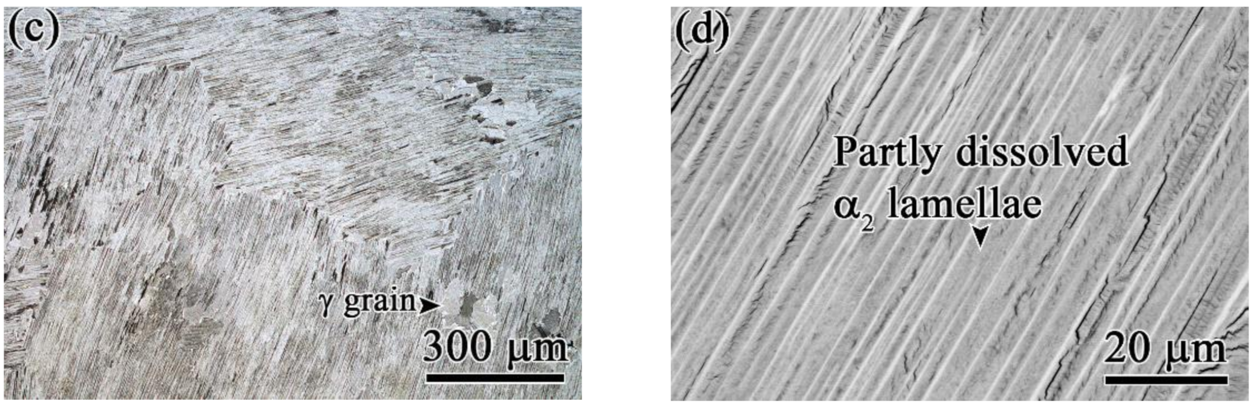
The lamellar structure is stable after the HIP process, and the subsequent HTs in α + γ phase field reduces the colony size slightly by the precipitation of γ grains at colony boundaries.
(3)
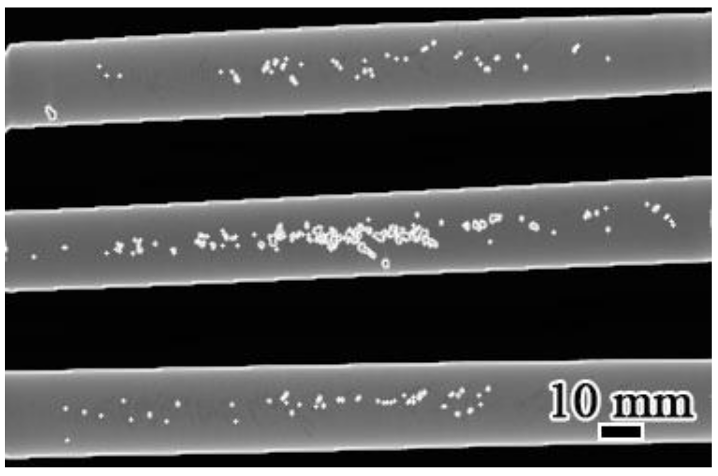
The colony size in the central area after HTs is affected not only by the HT temperature but also by the amount of shrinkage porosities in the as-cast bar. Compared to HT1 and HT2 bars, the HT3 bar, with the more shrinkage porosities in as-cast condition, obtains a smaller colony size.
(4)
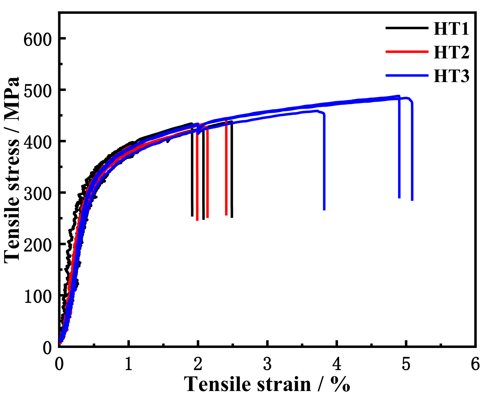
The yield strengths after three HTs are nearly same, but a greater elongation is obtained after HT3. The smaller colony size after HT3 should be responsible for this greater elongation.

Author Contributions

Conceptualization and writing—original draft preparation, W.Y.; methodology and formal analysis, X.D. and J.L.; validation, J.Z., Y.Y.; writing—review and editing, X.F. and W.D.; funding acquisition, H.N. All authors have read and agreed to the published version of the manuscript.

Funding

This research was funded by the National Key Research and Development Program of China, grant number 2020YFB1710100, the National Natural Science Foundation of China, grant number 51671026, the State Key Lab of Advanced Metals and Materials, grant number 2019-ZD05, and National Key R&D Program of China, grant number 2018YFB1106000.

Institutional Review Board Statement

Not applicable.

Informed Consent Statement

Not applicable.

Data Availability Statement

Data sharing not applicable.

Conflicts of Interest

The authors declare no conflict of interest.

References

  1. Clemens, H.; Mayer, S. Intermetallic titanium aluminides in aerospace applications–processing, microstructure and proper-ties. Mater. High. Temp. 2016, 33, 1–11. [Google Scholar] [CrossRef]
  2. Appel, F.; Clemens, H.; Fischer, F.D. Modeling concepts for intermetallic titanium aluminides. Prog. Mater. Sci. 2016, 81, 55–124. [Google Scholar] [CrossRef]
  3. Dimiduk, D.M. Gamma titanium aluminide alloys—an assessment within the competition of aerospace structural materials. Mater. Sci. Eng. A 1999, 263, 281–288. [Google Scholar] [CrossRef]
  4. Kim, Y.-W. Intermetallic alloys based on gamma titanium aluminide. JOM 1989, 41, 24–30. [Google Scholar] [CrossRef]
  5. Clemens, H.; Smarsly, W. Light-Weight Intermetallic Titanium Aluminides–Status of Research and Development. Adv. Mater. Res. 2011, 278, 551–556. [Google Scholar] [CrossRef] [Green Version]
  6. Wu, X. Review of alloy and process development of TiAl alloys. Intermetallics 2006, 14, 1114–1122. [Google Scholar] [CrossRef]
  7. Lasalmonie, A. Intermetallics: Why is it so difficult to introduce them in gas turbine engines? Intermetallics 2006, 14, 1123–1129. [Google Scholar] [CrossRef]
  8. Appel, F.; Brossmann, U.; Christoph, U.; Eggert, S.; Janschek, P.; Lorenz, U.; Müllauer, J.; Oehring, M.; Paul, J.D.H. Recent Progress in the Development of Gamma Titanium Aluminide Alloys. Adv. Eng. Mater. 2000, 2, 699–720. [Google Scholar] [CrossRef]
  9. Larsen, D.E. Status of investment cast gamma titanium aluminides in the USA. Mater. Sci. Eng. A 1996, 213, 128–133. [Google Scholar] [CrossRef]
  10. Kim, Y.-W. Ordered intermetallic alloys, part III: Gamma titanium aluminides. JOM 1994, 46, 30–39. [Google Scholar] [CrossRef]
  11. Lipsitt, H.A. Titanium Aluminides—An Overview. MRS Online Proc. Library Arch. 1984, 39. [Google Scholar] [CrossRef]
  12. Blackburn, M.J.; Smith, M.P. Titanium Alloys of the TiAl Type. U.S. Patent 4,294,615, 13 October 1981. [Google Scholar]
  13. Kim, Y.W.; Kim, S.L. Advances in Gammalloy Materials-Processes-Application Technology: Successes, Dilemmas, and Future. JOM 2018, 70, 553–560. [Google Scholar] [CrossRef] [Green Version]
  14. Bewlay, B.P.; Nag, S.; Suzuki, A.; Weimer, M.J. TiAl alloys in commercial aircraft engines. Mater. High Temp. 2016, 33, 549–559. [Google Scholar] [CrossRef]
  15. Kim, J.K.; Kim, J.H.; Kim, J.Y.; Park, S.H.; Kim, S.W.; Oh, M.H.; Kim, S.E. Producing fine fully lamellar microstructure for cast gamma-TiAl without hot working. Intermetallics 2020, 120, 106728. [Google Scholar] [CrossRef]
  16. Aguilar, J.; Schievenbusch, A.; Kättlitz, O. Investment casting technology for production of TiAl low pressure turbine blades – Process engineering and parameter analysis. Intermetallics 2011, 19, 757–761. [Google Scholar] [CrossRef]
  17. Kim, Y.-W.; Dimiduk, D.M. Progress in the understanding of gamma titanium aluminides. JOM 1991, 43, 40–47. [Google Scholar] [CrossRef]
  18. Kelly, T.J.; Austin, C.M.; Allen, R.E. Processing of Gamma Titanium-Aluminide Alloy Using a Heat Treatment Prior to Deformation Processing. U.S. Patent 5,609,698, 11 March 1997. [Google Scholar]
  19. Kelly, T.J.; Bewlay, B.P.; Weimer, M.J.; Whitacre, R.K. Methods for Processing Titanium Aluminide Intermetallic Compositions. U.S. Patent 13/459,420, 31 December 1991. [Google Scholar]
  20. Kelly, T.J.; Weimer, M.J.; Austin, C.M.; London, B.; Larson, D.E.; Wheeler, D.A. Heat Treatment of Gamma Titanium Aluminide Alloys. U.S. Patent 6,231,699, 15 May 2001. [Google Scholar]
  21. Gao, Z.; Yang, J.; Wu, Y.; Hu, R.; Kim, S.-L.; Kim, Y.-W. A Newly Generated Nearly Lamellar Microstructure in Cast Ti-48Al-2Nb-2Cr Alloy for High-Temperature Strengthening. Met. Mater. Trans. A 2019, 50, 5839–5852. [Google Scholar] [CrossRef]
  22. Gloanec, A.-L.; Henaff, G.; Bertheau, D.; Belaygue, P.; Grange, M. Fatigue crack growth behaviour of a gamma-titanium-aluminide alloy prepared by casting and powder metallurgy. Scr. Mater. 2003, 49, 825–830. [Google Scholar] [CrossRef]
  23. Recina, V.; Karlsson, B. High temperature low cycle fatigue properties of Ti-48Al-2Cr-2Nb gamma titanium aluminides cast in different dimensions. Scr. Mater. 2000, 43, 609–615. [Google Scholar] [CrossRef]
  24. Mercer, C.; Lou, J.; Soboyejo, W.O. An investigation of fatigue crack growth in a cast lamellar Ti-48Al-2Cr-2Nb alloy. Mat. Sci. Eng. A 2000, 284, 235–245. [Google Scholar] [CrossRef]
  25. Harding, T.S.; Jones, J.W. Fatigue thresholds of cracks resulting from impact damage to γ-TiAl. Scripta. Mater. 2000, 43, 623–629. [Google Scholar] [CrossRef] [Green Version]
  26. Hénaff, G.; Cohen, S.A.; Mabru, C.; Petit, J. The role of crack closure in fatigue crack propagation behaviour of a TiAl-based alloy. Scripta. Mater. 1996, 34, 1449–1454. [Google Scholar] [CrossRef]
  27. Jeon, J.-H.; Godfrey, A.B.; Blenkinsop, P.A.; Voice, W.; Hahn, Y.-D. Recrystallization in cast 45-2-2 XD™ titanium aluminide during hot isostatic pressing. Mater. Sci. Eng. A 1999, 271, 128–133. [Google Scholar] [CrossRef]
  28. Charpentier, M.; Daloz, D.; Gautier, E.; Lesoult, G.; Hazotte, A.; Grange, M.; Charpentier, M.; Daloz, D.; Gautier, E.; Lesoult, G.; et al. Study of microstructure and solute partitioning in a cast Ti-48Al-2Cr-2Nb alloy by quenching during directional solidification technique. Met. Mater. Trans. A 2003, 34, 2139–2148. [Google Scholar] [CrossRef]
  29. Shong, D.; Kim, Y.-W. Discontinuous coarsening of high perfection lamellae in titanium aluminides. Scr. Met. 1989, 23, 257–261. [Google Scholar] [CrossRef]
  30. Jung, J.; Park, J. Growth kinetics of discontinuous coarsening of lamellar structure in Ti-44 at.% Al-0.5 at.%Cr intermetallic compounds. Acta Mater. 1998, 46, 4123–4130. [Google Scholar] [CrossRef]
  31. Denquin, A.; Naka, S. Phase transformation mechanisms involved in two-phase TiAl-based alloys—II. Discontinuous coars-ening and massive-type transformation. Acta Mater. 1996, 44, 353–365. [Google Scholar] [CrossRef]
  32. Muñoz-Moreno, R.; Ruiz-Navas, E.M.; Boehlert, C.J.; Llorca, J.; Torralba, J.M.; Pérez-Prado, M.T. Analysis of crystallographic slip and grain boundary sliding in a Ti-45Al-2Nb-2Mn-0.8vol%TiB2 alloy by high temperature in-situ mechanical testing. Mat. Sci. Eng. A 2014, 606, 276–289. [Google Scholar] [CrossRef] [Green Version]
  33. Muñoz-Moreno, R.; Boehlert, C.J.; Pérez-Prado, M.T.; Ruiz-Navas, E.M.; Llorca, J. In situ Observations of the Deformation Be-havior and Fracture Mechanisms of Ti-45Al-2Nb-2Mn-0.8vol%TiB2 XD. Metall. Mater. Trans. A 2012, 43, 1198–1208. [Google Scholar] [CrossRef] [Green Version]
  34. Muñoz-Moreno, R.; Pérez-Prado, M.T.; Llorca, J.; Ruiz-Navas, E.M.; Boehlert, C.J. Effect of Stress Level on the High Tempera-ture Deformation and Fracture Mechanisms of Ti-45Al-2Nb-2Mn-0.8vol%TiB2: An In-Situ Experimental Study. Metall. Mater. Trans. A 2013, 44, 1887–1896. [Google Scholar] [CrossRef] [Green Version]
  35. Boehlert, C.J.; Hernández-Escobar, D.; Ruiz-Palenzuela, B.; Sabirov, I.; Cornide, J.; Ruiz Navas, E.M. The effect of micro-structure and strain rate on the 25 °C and 700 °C compression deformation behavior of powder metallurgy processed Ti-45Al-2Nb-2Mn (at.%)-0.8v.%TiB2 alloy. Mater. Charact. 2021, 172, 110856. [Google Scholar] [CrossRef]
  36. Kestler, H.; Clemens, H. Production, Processing and Application of γ(TiAl)-Based Alloys. In Titanium and Titanium; Wiley-VCH: Weinheim, Germany, 2005; pp. 351–392. [Google Scholar]
  37. Kim, Y.W. Microstructural evolution and mechanical properties of a forged gamma titanium aluminide alloy. Acta Met. Mater. 1992, 40, 1121–1134. [Google Scholar] [CrossRef]
  38. Wang, J.; Xie, K. Grain size refinement of a TiAl alloy by rapid heat treatment. Scr. Mater. 2000, 43, 441–446. [Google Scholar] [CrossRef]
  39. Ding, J.; Zhang, M.; Ye, T.; Liang, Y.; Ren, Y.; Dong, C.; Lin, J. Microstructure stability and micro-mechanical behavior of as-cast gamma-TiAl alloy during high-temperature low cycle fatigue. Acta Mater. 2018, 145, 504–515. [Google Scholar] [CrossRef]
  40. Liu, C.T.; Maziasz, P.J. Microstructural control and mechanical properties of dual-phase TiAl alloys. Intermetallics 1998, 6, 653–661. [Google Scholar] [CrossRef]
Figure 1. Initial as-cast microstructures of the 4722 alloy: (a) OM macrostructure; (b) OM microstructure, edge region; (c) OM microstructure, central area; (d) SEM-BSE microstructure.
Metals 11 01156 g001
Figure 2. Casting defect inspection in the 4722 alloy bars by X-ray before HIP.
Metals 11 01156 g002
Figure 3. Casting defect inspection in the 4722 alloy bars by X-ray after HIP.
Metals 11 01156 g003
Figure 4. Typical microstructures of an as-HIPed 4722 alloy: (a) OM macrostructure; (b) OM microstructure, edge region; (c) OM microstructure, central area; (d) SEM-BSE microstructure, central area.
Metals 11 01156 g004
Figure 5. Microstructures of the 4722 alloy after HT1: (a) OM macrostructure; (b) OM microstructure, edge region; (c) OM microstructure, central area; (d) SEM-BSE microstructure, central area.
Metals 11 01156 g005
Figure 6. Microstructures of the 4722 alloy after HT2: (a) OM macrostructure; (b) OM microstructure, edge region; (c) OM microstructure, central area; (d) SEM-BSE microstructure, central area.
Metals 11 01156 g006aMetals 11 01156 g006b
Figure 7. Microstructures of the 4722 alloy after HT3: (a) OM macrostructure; (b) OM microstructure, edge region; (c) OM microstructure, central area; (d) SEM-BSE microstructure, central area.
Metals 11 01156 g007
Figure 8. Tensile curves at 700 °C for the tensile samples after different HTs.
Metals 11 01156 g008
Figure 9. Variations of tensile properties at 700 °C with colony size.
Metals 11 01156 g009
Figure 10. Fracture morphology of tensile samples at 700 °C: (a,b) HT1; (c,d) HT3.
Metals 11 01156 g010
Table 1. Chemical composition of the 4722 alloy (at%).
TiAlCrNbO
Bal.47.012.022.090.13
Table 2. HT parameters applied to the 4722 alloy in this study.
HT No.HT Parameters
HT11185 °C, 6 h, FC
HT21280 °C, 4 h, FC
HT31310 °C, 4 h, FC
Table 3. Microstructural parameters after three HTs.
HT1HT2HT3
EdgeCentralEdgeCentralEdgeCentral
MicromorphologyNLNLNL
Colony size/μm355331367347386243
Colony fraction/pct74.285.682.190.790.995.9
γ grain size/μm657652634660
γ grain fraction/pct25.814.417.99.39.14.1
Publisher’s Note: MDPI stays neutral with regard to jurisdictional claims in published maps and institutional affiliations.

