Article

Studies on the Formation and Processing of Aluminium Dross with Particular Focus on Special Metals

by
Stefan Wibner
1,*,
Helmut Antrekowitsch
1 and
Thomas C. Meisel
2
1
Nonferrous Metallurgy, Montanuniversitaet Leoben, 8700 Leoben, Austria
2
General and Analytical Chemistry, Montanuniversitaet Leoben, 8700 Leoben, Austria
*
Author to whom correspondence should be addressed.
Metals 2021, 11(7), 1108; https://doi.org/10.3390/met11071108
Submission received: 2 June 2021 / Revised: 3 July 2021 / Accepted: 6 July 2021 / Published: 12 July 2021
(This article belongs to the Special Issue Metallurgy and Recycling of Nonferrous Metals)

Abstract

:
In terms of production volume, aluminium is the leading metal in non-ferrous metallurgy. In particular, the recycling of aluminium-containing residues has strongly increased in recent years and will continue to gain importance in the future. Due to the high affinity of aluminium to oxygen, the oxidation of the molten bath is unavoidable, which leads to the formation of dross on the surface. This has a high content of metallic aluminium and therefore represents a valuable residual material that must be further processed. In the presented work, a study is conducted on the formation and possible further processing of aluminium dross. Within the scope of this experimental work, the pyrometallurgical treatment of Al-dross in the salt drum furnace was evaluated on the basis of an experiment in a TBRC (top blown rotary converter) by adding a salt mixture. In addition, the behaviour of special metals, in particular the rare earth elements (REEs), was investigated during such a melting process. This knowledge will be particularly important in the future, as inadequate scrap processing leads to more of these partially valuable contaminants entering the aluminium scrap cycle. The result of the experimental study was that the metal yield of the dross used in the melting experiment at the Chair of Nonferrous Metallurgy was higher than that achieved by external reprocessing. Regarding the distribution of the rare earths, there was a direct transition of these from the dross into the emerging salt slag phase.

1. Introduction

Aluminium is the leading metal in non-ferrous metallurgy in terms of volume, with an annual production of 81.1 million metric tons in 2019, of which around 16.8 million metric tons were produced in secondary metallurgy. The relevance of aluminium recycling has significantly increased in recent years and will continue to gain importance in the future. One residue that accumulates during the processing of aluminium in smelters and foundries is dross [1].
First of all, this article deals with the formation of aluminium dross and the typical process routes for processing it, explaining its potential in terms of the “zero waste concept”. In this context, pyrometallurgical investigations at the Chair of Nonferrous Metallurgy at the Montanuniversitaet Leoben served to determine the metal yield of dross that originates from an Austrian aluminium recycling plant. For this purpose, a certain amount of this residual material was processed in a TBRC (top blown rotary converter) by the addition of smelting salt. The TBRC is comparable to a tilting drum furnace that is often used in the aluminium recycling industry. The purpose of this experiment was to verify the metal yield obtained during dross processing, which was carried out by an external company for the regarded Austrian smelting plant.
Furthermore, this research investigated the distribution of special metals, rare earth metals in this case, between the phases occurring during the smelting process. This is of essential interest because it can be assumed that an increased proportion of such elements will be present in the secondary aluminium metallurgy in the future due to their numerous applications.

1.1. Formation and Composition of Aluminium Dross

Dross is an aluminium-containing residue that arises during smelting, a melt treatment and the casting of aluminium and its alloys in primary smelters, foundries, and recycling plants. On the one hand, the natural oxide layer leads to the formation of dross during the remelting of solid feedstocks, such as aluminium scrap. On the other hand, dross also results from the turbulence and movement of the melt during furnace work (charging, refining, etc.). Incorporated and newly formed oxides cause considerable amounts of these residues, as the reduction of Al2O3 to metal in the industrial recycling process is not economically feasible. Statistically, about 20–30 kg of dross are generated per metric ton of secondary aluminium produced [2,3,4,5].
The high oxygen affinity of the metal is essential for the formation of dross. The corresponding oxidation reaction is shown in Equation (1). This is strongly exothermic, which means that temperatures of up to 1400 °C can occur inside the dross. The reaction ends at values below 400 °C [2,6].
4 Al(l) + 3 O2(g) ⇄ 2 Al2O3(s)
Due to the prevailing process conditions in the smelting unit and furnace, the oxide layer that forms constantly breaks down. The charging of new feedstock also results in this effect. In the generated dross, cavities filled with metal and gas bubbles are formed. Compared to liquid Al, aluminium oxide has a higher density of 3.98 g/cm3 at 700 °C (liquid Al: 2.36 g/cm3 at 700 °C). However, due to the porosity of the dross, it floats on the surface of the molten bath. Investigations by Manfredi et al. [7] showed that dross in granular form has a filling density of 0.828–1.118 g/cm3, which clearly demonstrates this effect [2,7,8].
According to Alfaro [9], the formation of dross can be divided into eight sub-steps [8,9,10]:
  • Formation of the oxide layer on the melt surface.
  • Breaking of the oxide skin by bath movement.
  • Sinking and floating of some oxide particles.
  • Adhesion of the oxide particles.
  • Filling of the cavities with metallic aluminium (capillary action).
  • Oxidation of the metallic aluminium finely dispersed in the dross.
  • Skimming.
  • Processing of the dross outside the furnace.
Aluminium dross, which in principle can be assigned to new scrap, consists of up to 80% of metallic Al, aluminium oxides in various forms (α and γ), and Al nitride. In addition, silicon, iron, calcium, and magnesium oxides (as well as other Al compounds such as carbides, chlorides, and fluorides) are present in small quantities. Aluminium carbide is formed by the introduction of organic substances, e.g., paintings or surface coatings, via the scrap into the Al melt, resulting in an exothermic reaction with carbon. Halogenides originate from the melt refining with purge gases, as well as from the smelting salt. The formation of spinels results from the (at least locally) high temperatures due to the strongly exothermic oxidation reactions. Initially, magnesium oxides are formed in the dross, which, in turn, transform into spinels (MgAl2O4) with aluminium oxide [2,11,12,13].

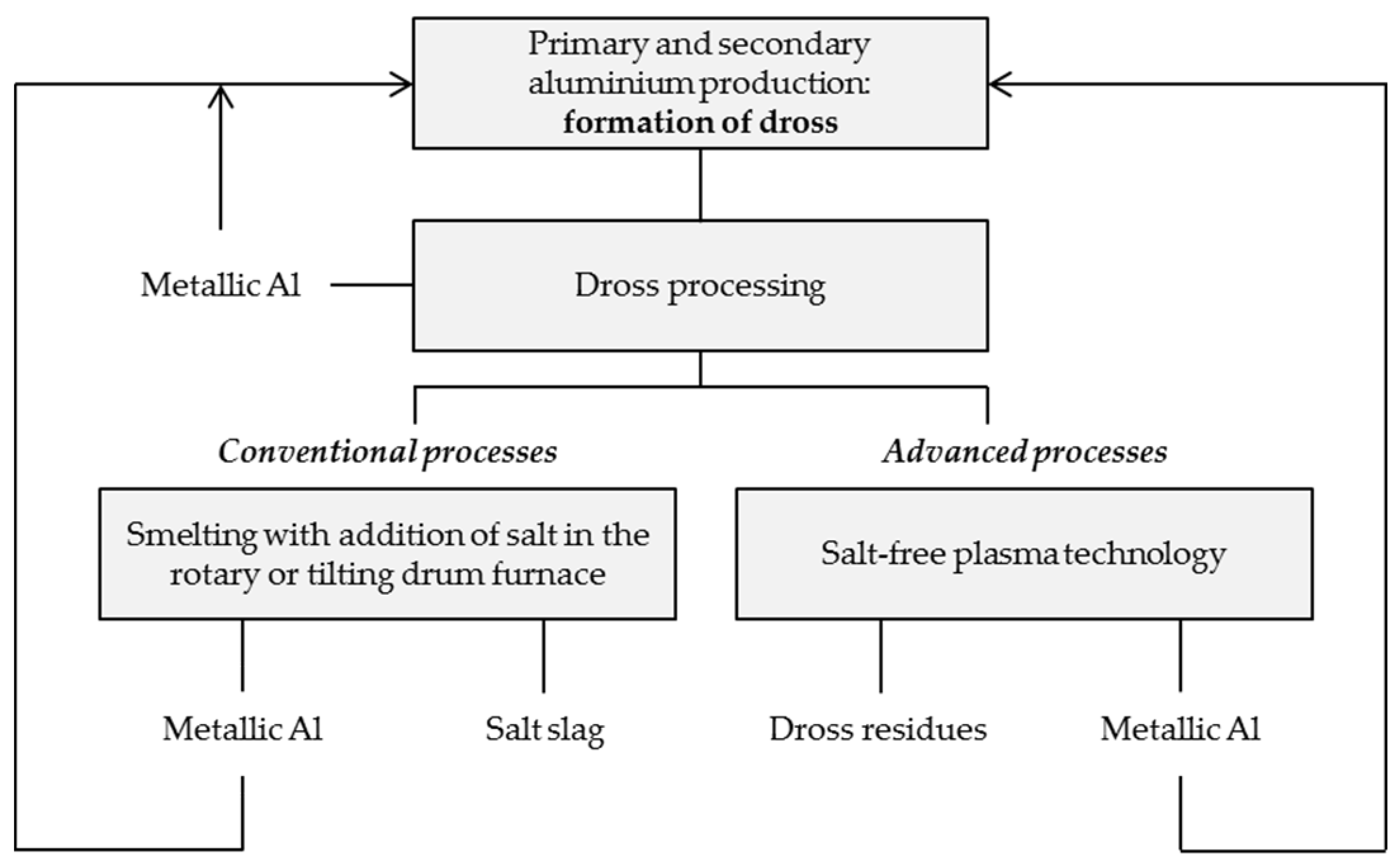
1.2. Processing of Aluminium Dross

Due to the high metallic content of the dross, reprocessing is essential. The associated process diagram is shown in Figure 1. The residual material formed in primary or secondary production is first subjected to dross processing, which involves either the processing of hot dross or the mechanical treatment of already cooled dross. The former is carried out by shaking, stirring, pressing, or centrifuging, whereby a recovery of up to 50% of the contained metallic aluminium is possible. Here, the pressing processes are the most effective, as higher metal losses occur due to the initiated movement during the stirring processes. The recovered metallic aluminium is again charged into the smelting process. The dross residues, which accumulate after treatment, are fed to the conventional melting process in a rotary or tilting drum furnace using salt. The metallic aluminium obtained in this process is then returned to the production process [5,14,15,16,17].
Another option in dross processing is rapid cooling after skimming, such as inert gas treatment with argon. The cooled dross is then processed by repeated crushing and screening, whereby the produced residual materials are critical due to their reactivity (formation of H2, ammonia, chlorides, etc.) and the low metallic Al content. The mechanical action of the crushers causes different deformations of the materials. The metallic fractions plastically deform under load, and non-metallic components break due to their brittleness, resulting in material separation. The further processing of the coarse fraction, which has a higher Al content, is carried out in drum furnaces with the addition of smelting salt. Dross residues, collected in the fine fraction, can be used as casting powder in the steel industry under limited conditions, and the resulting dusts currently have no subsequent use. The landfilling of these is problematic due to gas formation upon contact with water [5,14,15,16,17].
The main processing of dross, especially in Europe, is via the smelting process because, in combination with the subsequent salt slag treatment, residues to be landfilled can be avoided. The processing of the salt slag results in products such as metallic aluminium and recycling salt (which are in turn fed into the secondary aluminium metallurgy) and an alumina-containing residue that is used in the building materials industry. In the context of dross processing, both mechanical and pyrometallurgical recycling in combination with salt slag treatment should aim for closed-loop recycling in order to implement low-residue or residue-free concepts in the sense of the European circular economy. The ecological problems of salt slags are the water-solubility of the chlorides, which can lead to the salinisation of the groundwater, and the formation of partly explosive or toxic gases such as H2, CH4, NH3, PH3, and H2S when the slags come into contact with water or moisture [5,14,15,16,17].
Advanced processes, which have been introduced into the processing of aluminium dross in recent years, are based on plasma technology. The aim here is to expose the metallic aluminium trapped in the dross and to produce residues with minimal environmental impact. The advantage of these technologies is primarily in the elimination of smelting salt additives, results in no salt slag being produced. In this context, the ALUREC [17], ECOCENT [18], DROSRITE [18], and DROSCAR [18] processes should be mentioned. The Alcan plasma dross treatment is also important. For more detailed explanations of these processes, please refer to the work of Meshram and Singh [17] and Ünlü and Drouet [18]. It can be inferred that Alcan, DROSCAR, and ALUREC have either plasma arc technology or external fuel for heating the feed, whereas processes like ECOCENT and DROSRITE use the heat that is available in the hot dross. The resulting dross residue does not contain salt and thereby ensures a low environmental hazard and improved metal recovery. However, the increased energy input compared to the conventional salt drum furnace process should be mentioned as a disadvantage [16,17,18].

1.3. Special Metals in the Aluminium Recycling Process

The behaviour of special metals such as lithium, indium, gallium, selenium, tellurium, and rare earths in the aluminium recycling process is still largely unexplored. In the future, however, it is to be expected that these elements will increasingly access secondary aluminium metallurgy as the areas of application for these and the complexity of newly developed alloys are raised. Additionally the contamination of scraps by other metals like Mg alloys, which contain special metals like rare earths, lead to this problem. In this research, the elements of the rare earths are to be considered with regard to their partitioning into the metal or salt slag phase arising during the remelting of aluminium-containing dross by the use of smelting salt. The rare earth elements (REEs) are found in the d- and f-blocks of the periodic table and contain the elements scandium (atomic number at. no. = 21), yttrium (at. no. = 39), and the 15 lanthanides (at. no. = 57–71). The atomic weight steadily increases with increasing atomic number. Thus, the molar mass of lanthanum is 138.91 g/mol, and that of lutetium is 174.97 g/mol. These elements enter the aluminium cycle from their application areas due to inadequate scrap processing, where their behaviour is completely unknown. REEs are mainly used in glasses and ceramics, magnets, catalysts, batteries, and luminescent materials, where they are often present in the form of their oxides [19,20,21,22,23].
After the contents of the rare earth elements in different phases have been determined, it is essential to illustrate clearly and graphically them. Due to the high concentration differences between the individual REEs, it is necessary to logarithmically plot the normalised measurement results against the atomic number of the respective elements. If the REE mass fractions are presented without prior normalisation, a characteristic sawtooth curve is produced. This usually drops from the light to the heavy rare earths (see Figure 2a). Furthermore, the Oddo–Harkins rule, which states that elements with an even atomic number occur in nature with higher frequency than those with an odd one, can be recognised from this. Normalisation means that the measured REE mass fractions of a sample are divided by those of a reference [19].
The actual purpose of normalisation is to remove the characteristic sawtooth pattern so that different datasets can be better compared with each other. Chondrite normalisation represents the standard procedure here. In cosmochemistry, chondrites are classified as undifferentiated meteorites, which consist of small silicate spheres (the so-called chondrules) and a fine-grained matrix. They are suitable for normalisation because the composition of the Earth in terms of non-volatile elements corresponds to that of some chondrites. Table 1 summarises the mass fractions of lanthanides in chondrites, according to Wasson and Kallemeyn [24], which are used for normalisation. By examining the data, it can be seen that those for the element promethium are missing. This is due to the fact that all isotopes of Pm are radioactive and have short half-lives of less than 17.7 years. Thus, promethium is not detectable [19,25].
To illustrate the importance of normalisation, Figure 2 shows the measured REE mass fractions (Figure 2a) in mg/kg and the chondrite-normalised values of these (Figure 2b) using the example of the “Strange Lake Intrusion” near Quebec (Canada). Kerr [26] compared the REE mass fractions determined via a developed prediction model with the actually measured data. For more detailed descriptions, please refer to [26].
Due to the position of the REEs in the periodic table, they occur in nature almost exclusively as trivalent cations. Exceptions are the elements cerium and terbium, as well as europium and ytterbium; the first two can also occur in the tetravalent form, and the second two can occur in the divalent form. The so-called positive or negative Eu anomaly is due to the formation of divalent or trivalent europium ions. Furthermore, a disproportionation of divalent ytterbium halides into trivalent and elemental Yb can take place [19,27].
Rare earths exhibit strongly negative standard electrode potentials of about −2.3 V. Only that of europium, −1.99 V, is more positive. REEs are thus very ignoble and suitable as reducing agents. Regarding the Richardson Ellingham diagram, the position of the REE oxides in comparison to the aluminium oxide is particularly important, which is why the rare earths have a higher affinity for oxygen than metallic aluminium under standard conditions [27,28].

2. Materials and Methods

This section first describes the origin of the dross that is processed in the melting experiment in the TBRC. This is followed by a detailed description of the set parameters and the masses of added input materials for the TBRC trial. Finally, an explanation of the ICP–MS analysis (inductively coupled plasma with mass spectrometry), which is used to measure the contents of rare earths in the different phases, is given.

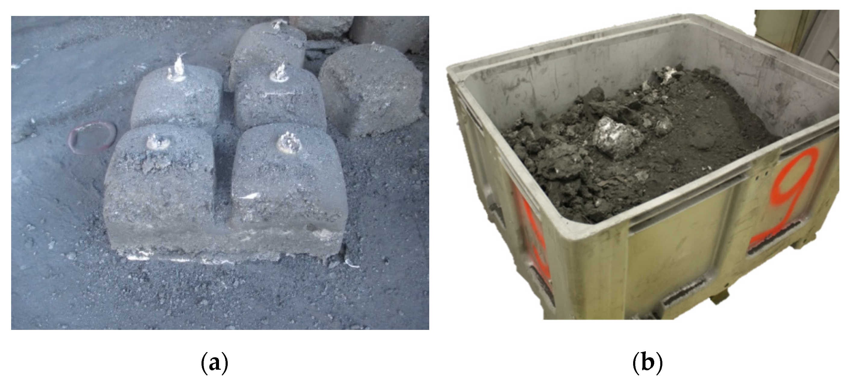
2.1. Origin of the Feedstock

The dross, which was used for the following pyrometallurgical experiments, was produced during the melting process of a scrap mixture at an Austrian aluminium recycling plant, where new scrap (as well as strongly contaminated post-consumer scrap) is charged in the forehearth of a two-chamber furnace. During the charging process, the material is placed on the bridge of the furnace by means of a wheel loader. There, the scrap mixture is preheated and pyrolyzed, which causes varnish and plastics to volatilise. With the following scrap batches, the preceding, already preheated and smouldered charge materials are pushed into the metal bath. The charging process takes about 1.5 h, with the total batch mass amounting to about 20 metric tons. After that, the skimming process begins. For this purpose, a special device is mounted on the wheel loader, which is first used to stir floating material into the liquid melt. Then, the dross containers are placed in front of the furnace by means of a forklift truck. Next, the dross is removed from the scrap chamber across the entire width of the furnace, collected on the bridge, and then filled into the dross containers. Lift trucks transport these containers to a dross press, with the aim to recover metallic aluminium that is charged into the two-chamber furnace again. Compacted dross remains as residue, which is shown in Figure 3a in intermediate storage under a roof. Afterwards, metallic aluminium is recovered from the dross compacts by remelting in a salt drum furnace. For the regarded Austrian smelting plant, this process step takes place externally, with an average Al yield of 61–62%. This was to be verified by the laboratory experiment in the TBRC, whereby a representative method that could determine the corresponding metal yield within narrow limits could also be developed.
In order to be able to carry out further processing on a laboratory scale at the Chair of Nonferrous Metallurgy, it was necessary to first crush such dross compacts. These partly consisted of oxides and other impurities that have a high hardness and brittleness. The majority, however, come in the form of metallic aluminium, which is very ductile. Crushing is therefore difficult due to impact stress, which is why crushers are not the optimal choice as processing aggregates. Therefore, the grinding of the compacts was carried out in a guillotine shear. With this aggregate, optimal cutting, whereby pieces that were too large were processed again manually by means of alligator shears, was possible. Figure 3b shows the processed dross compacts. These were then partly fine-grained and in the form of chunks with a size of more than 10 cm.

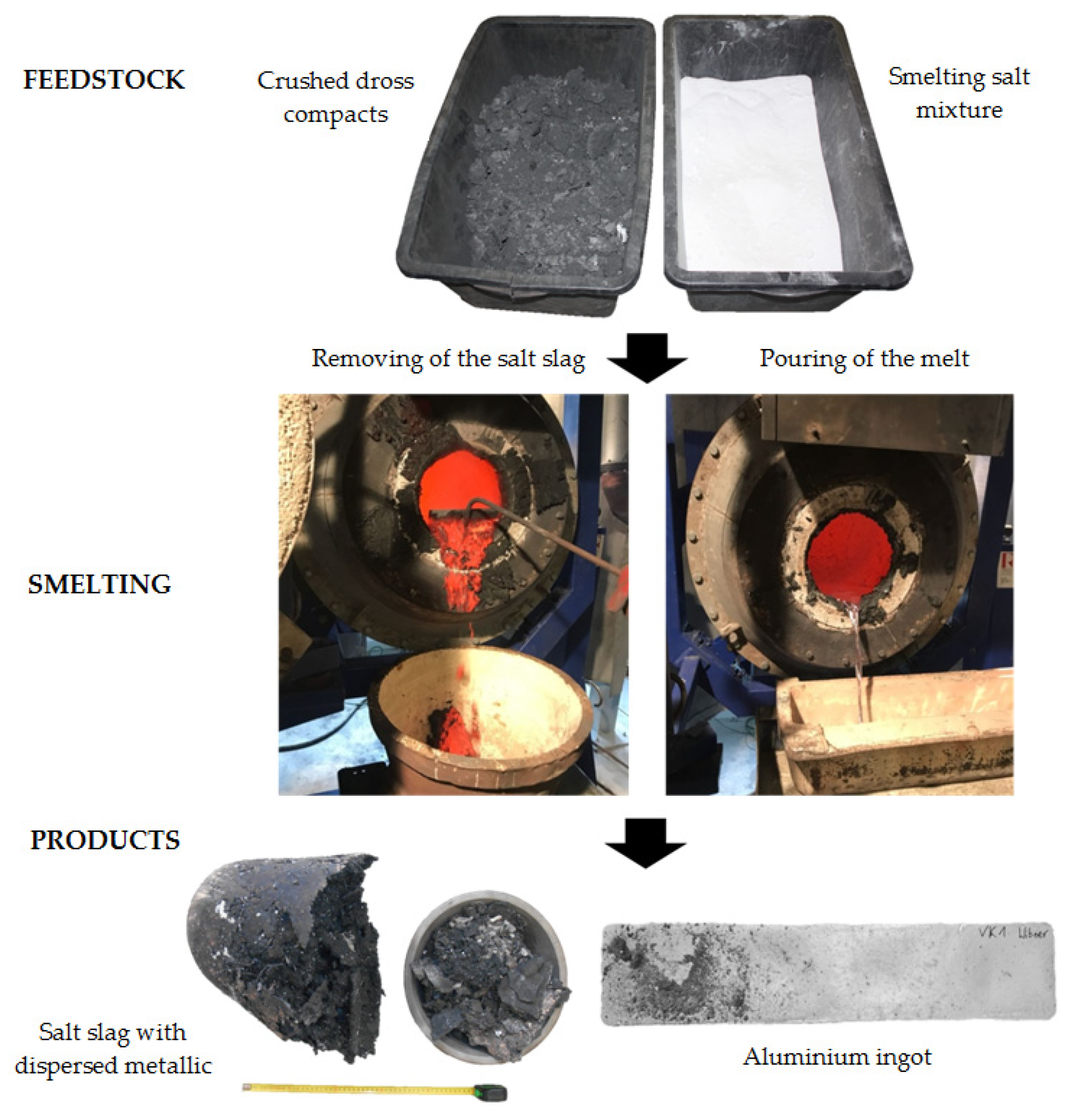
2.2. Pyrometallurgical Treatment of the Dross in the TBRC

The melting experiment of the previously described feedstock to determine the metallic aluminium content was carried out in the TBRC. Here, on the one hand, relatively large quantities of dross could be used to ensure a sample that was as representative as possible, and, on the other hand, the process conditions that are common in operational practice could be reproduced very well. The TBRC was heated by a methane–oxygen burner located in the lid. The flame was directed towards the refractory lining of the cylindrical furnace vessel so that the heat transfer to the feed material took place indirectly in order to counteract undesired oxidation.
The following furnace parameters were set for the experiment:
  • Flow rate of combustion air or fuel gas during melting operation: 3–8 m3/h (for the heating process: 11 m3/h).
  • Stoichiometric combustion air ratio: λ = 1
  • Setpoint temperature inside the furnace: approximately 750 °C (adjustable via flow rate).
  • Kiln tilt angle: approximately 95°.
  • Number of revolutions of the furnace vessel: 1 min−1.
After the TBRC was electrically preheated, further heating was carried out by means of a methane–oxygen burner. Crushed dross pieces (referred to as dross hereafter) and smelting salt (which was a mixture by mass of 70% NaCl, 30% KCl, and 2% CaF2) served as feed material. To make it easier to manually charge these materials into the furnace, they were packed in subsets of 5 kg in paper bags. In total, 35 kg of dross and 25 kg of smelting salt were charged into the TBRC (mdross:msalt = 1.4:1). Generally, 50–100% of the scrap mass of salt were added to the smelting sample during Al recycling. At the beginning, the heating process to about 800 °C took place, and then 10 kg of salt were added to prevent the oxidation of aluminium from the subsequently charged dross by means of a salt bath initially present in the TBRC. The interior of the furnace was visually checked, and depending on the flow-behaviour of the material in the furnace, dross or salt was charged. Here, the viscosity of the mixture during the kiln rotation was the most important parameter. This parameter resulted in the following charging process: 10 kg of salt, 5 kg of dross, 5 kg of salt, 5 kg of dross, 5 kg of salt, 15 kg of dross, 5 kg of salt, 10 kg of dross. The charging of these input materials took about 150 min. The temperature in the TBRC was around 750 °C. After about 410 min counted from the preheating process, the tapping, whereby the furnace was tilted, took place and the salt slag was removed first. The molten aluminium was then poured into a mould.
The process sequence for the melting experiment in the TBRC is shown in Figure 4.
Figure 4 first shows the crushed dross compacts and the salt mixture in the corresponding plastic containers as input materials. The manual removal of the salt slag and the casting of the aluminium melt are also shown. The products were metallic aluminium in ingot form and salt slag (see Figure 4), which still contained aluminium in the form of finely dispersed particles. In order to recover these, the slag was ground and sieved. Subsequently, the slag was divided into particle size ranges, whereby >1 mm and 0.5–1 mm were mostly metallic Al. The metallic Al was leached with hot water to remove adhering salt slag residues and then dried afterwards. The fine chips comprised the brittle-crushing salt slag with small amounts of metallic Al.
ICP–MS analysis was used to determine the REE contents in the individual fractions of the TBRC trial. Regarding sample preparation, the generation of fine chips from the solidified ingots was required for the metallic phases, and the grinding of the samples in a vibrating disk mill was required for the salt fractions. These solid sample materials were used to carry out Na2O2 sinter digestions, followed by ICP–MS according to the work of Bokhari and Meisel [29]. By means of ICP–MS, detection limits in the range of ng/L (partly also pg/L) can be achieved for most elements of the periodic table. Furthermore, the method is characterised by an extremely high linear range in quantitative determination [30].

3. Results

The mass balance for the melting experiment in the TBRC is summarised in Table 2. The metal yield II, which describes the percentage ratio of metallic aluminium directly recovered in the salt bath furnace to the quantity of dross charged, is of considerable interest. This amounted to 75.7%. The metal yield I also took the proportion of metallic aluminium contained in the salt slag into account and amounted to 81.6%.
During the remelting of the dross with the addition of smelting salt in the TBRC, the rare earths in the recovered metallic Al ingot, the salt slag, and the smelting salt were measured using ICP–MS analysis. These could not be directly measured in the dross due to its high inhomogeneity. With the help of the mass balance, which is shown in Table 2, the unknown REE mass fractions in the dross could be determined. A summary of these contents in the phases occurring during the melting experiment is given in Table 3, whereby a summation of the scandium, yttrium, and lanthanide mass fractions of the individual phases is also given.
Figure 5a shows the chondrite-normalised mass fractions of the lanthanides in the different phases occurring during the remelting of the dross using liquid salt in the TBRC. If the proportions of REEs exactly corresponded to those in chondritic meteorites, then a horizontal line would be shown here at a value of 1.0. In order to better illustrate the behaviour of the rare earths during the melting process, these were normalised to the REE mass fractions of the produced metallic aluminium (see Figure 5b).

4. Discussion

The first important result was the metal yield of aluminium, which arose from the dross processing. Metal yield II amounted to 75.7% and was thus about 14% higher than that achieved by external dross processing (61–62%). It should be noted that a liquid salt slag was used in the experiment in the TBRC in order to recover as much aluminium as possible. In practice, crumbly slag is often used, which could result in a lower yield. Nevertheless, in view of the annual production of aluminium at the regarded aluminium smelting plant and the resulting high dross quantities, the possible savings potential through the optimisation of the dross treatment process is enormous.
Metallic iron was also found in the salt slag. More precisely, this was a ferromagnetic material that was isolated by magnetic separation. This came from steel scrap, which was present in the aluminium scrap that was charged into the two-chamber furnace. Some of these substances then ended up in the dross, which also explains the iron content of 0.16 kg in the salt slag after the melting process in the TBRC.
The metal yield I amounted to 81.6% and was thus 5.9% higher than yield II. However, since a certain proportion of metallic Al also remained in the salt slag in the industrial process, the previously determined 75.7% represented the better comparative value. In addition, it should be noted that the proportion of aluminium remaining in salt slag in the industrial process is much higher (about 10% Al or even higher in some cases) [2].
The determination of the REE values in the different phases of the melting process showed that the total mass fractions were highest in the dross with 17.8 mg/kg and in the salt slag with 18.5 mg/kg according to Table 3. They were lower in the produced metallic Al (total REEs: 4.5 mg/kg) and in the added smelting salt (total REEs: 2.2 mg/kg). As mentioned in Section 1.3, the REEs are mainly introduced via the scrap into the aluminium recycling process in the two-chamber furnace, and they mainly originate from electronic scrap and the fluorescent sector due to insufficient scrap treatment. In most cases, they are present in oxide form. Due to the high affinity of REEs to oxygen, also in comparison to Al, no reduction of the rare earth oxides to the metal takes place through the aluminium melt. Therefore, they mainly accumulate in the oxide-rich phase, which is the formed dross. In the metal phase produced in the two-chamber furnace, the REE mass fractions are generally between 1.6 and 1.7 mg/kg [31] and are thus somewhat lower than these in the Al phase measured in the present research, which amounted to 4.5 mg/kg. When dross is remelted with the addition of salt, was done in this case in the TBRC, most of the REE pass into the formed salt slag, as can be assumed from the above-mentioned values.
In Figure 5a, negative Eu and Yb anomalies are evident in the produced metallic Al. In the dross and the salt slag, the Eu anomaly was positive because europium and ytterbium occur in both divalent and trivalent forms. Here, the ion radius also changed and was larger for divalent ions. It was assumed that Eu was present in the dross and metal phase in the trivalent (Eu2O3) and divalent or metallic forms, respectively. It could be determined that the rare earth elements that were contained in the dross largely passed directly into the salt slag. A change in the degree of ionisation did not take place, which could be proven by the constant positive anomalies of Eu in dross and salt slag.
In Figure 5b, the REE mass fractions are normalised to those in the metallic aluminium obtained by remelting the dross with the addition of salt. It can be seen that most of the rare earth elements contained in the salt or dross passed directly into the formed salt slag. A small part of them also remained in the aluminium due to the distribution equilibria between slag and metal phase.
As a comparison, the research work of Deady et al. [32], in which the contents of rare earths in European bauxites and red muds were determined, can be used. According to this work, the former contained REEs in concentrations of about 500 mg/kg (without scandium). During the processing of bauxite in the Bayer process, the rare earths accumulated in the red mud, so that mass fractions of up to 900 mg/kg (without Sc) occurred there. The bauxites investigated in this work were different rock layers of the karst bauxite deposits in the Greek regions around Mt. Parnassus, Mt. Giona, and Mt. Helikon. The red mud samples were from different dried landfills, and readers can see the work of Deady et al. [32] for more detailed descriptions. When comparing these REE mass fractions of bauxites and red mud (which were assigned to the primary aluminium metallurgy) with those measured in the secondary metallurgy in the present research work, it must be noted that they were much lower in the latter. With the exception of the dross and salt slag, the REE mass fractions were lower by a factor of 100–500. In the case of dross remelting with the addition of salt, the slightly higher REE mass fractions of 4.5 mg/kg in the metallic aluminium produced due to the distribution coefficients of the rare earths between the different phases could, however, have exerted effects in the metal, such as additional oxides and modifications of the dross and salt slag. In the metallic aluminium produced in the two-chamber furnace, the REE mass fractions were somewhat lower, as mentioned before.

5. Conclusions

The following investigations were carried out as part of the present work:
  • Within the framework of this research, a comprehensive study was conducted on the formation and further processing of aluminium dross.
  • In the experimental part, dross formed at an Austrian aluminium smelter was processed in the TBRC with the addition of smelting salt, and the proportion of metallic aluminium contained within was determined. The TBRC corresponded to a tilting drum furnace, which is usually used in secondary aluminium metallurgy for the remelting of dross. The result showed that a 75.7% metal yield could be obtained without taking the proportion of metallic Al in the salt slag into account. Compared to the current processing of the regarded dross, which is carried out externally and results in metal yields of 61–62%, a significant increase and therefore an enormous potential for economic savings are possible.
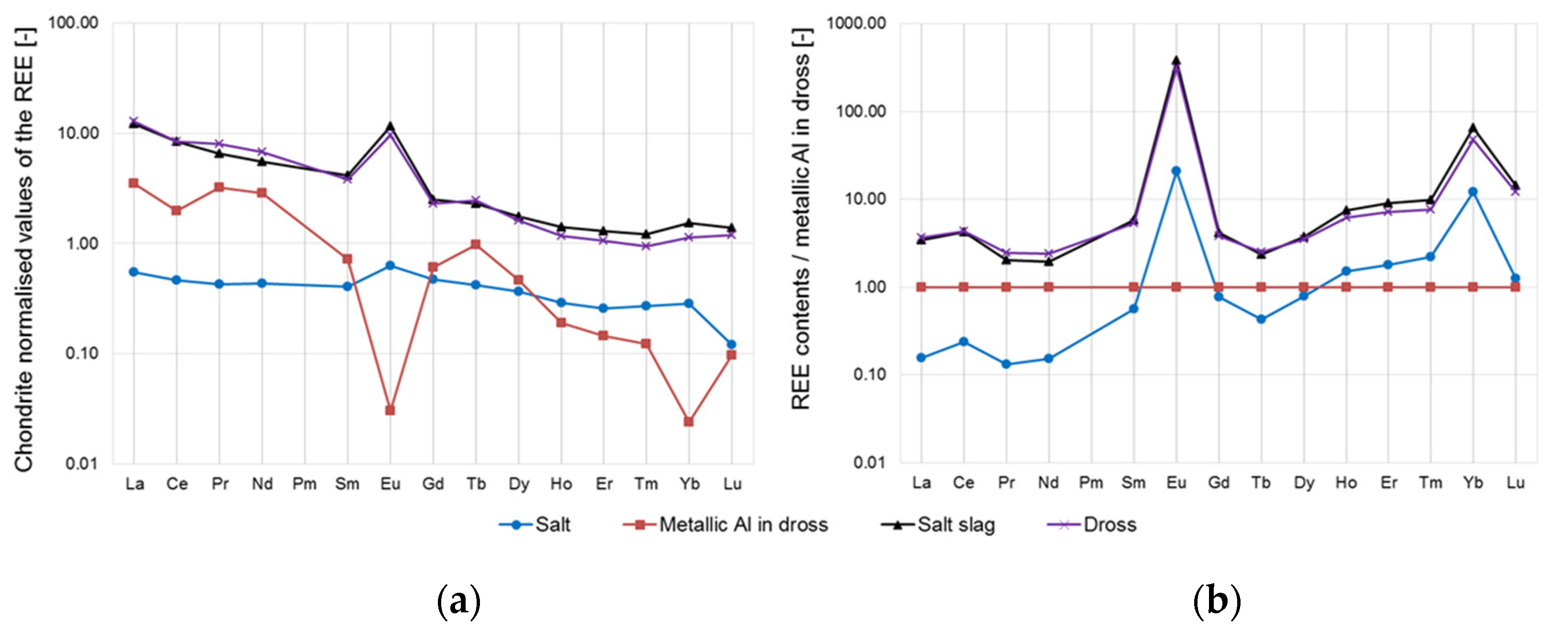
  • Another important part of this research was the investigation of the content of rare earths in the phases resulting from the smelting process, the salt slag, and the metallic aluminium. The REE mass fractions in the input materials, the dross, and the smelting salt mixture used were also determined. It was found that the majority of the REEs directly passed from the dross into the salt slag. Already during the remelting of aluminium scrap in the two-chamber furnace, the rare earths preferentially accumulated in the dross, whereby they mainly entered the melting process via the scrap in the form of their oxides. The oxidation state did not change during the transition from the dross to the salt slag, which could be demonstrated, in particular, by the constant europium anomaly. The behaviour of special metals, such as rare earths, in aluminium recycling still requires comprehensive research and will become more important in the future, since these elements will also increasingly enter the aluminium recycling cycle due to their growing usage.

Author Contributions

Conceptualization, S.W. and H.A.; methodology, S.W., H.A., and T.C.M.; investigation, S.W. and T.C.M.; writing—original draft preparation, S.W.; writing—review and editing, H.A. All authors have read and agreed to the published version of the manuscript.

Funding

This research was funded by The Austrian Research Promotion Agency (FFG).

Data Availability Statement

Data sharing is not applicable to this article.

Conflicts of Interest

The authors declare no conflict of interest. The funders had no role in the design of the study; in the collection, analyses, or interpretation of data; in the writing of the manuscript, or in the decision to publish the results.

References

  1. World Bureau of Metal Statistics. Metal Statistics 2009–2019, 107th ed.; World Bureau of Metal Statistics: Ware, UK, 2019. [Google Scholar]
  2. Krone, K. Aluminiumrecycling; Aluminium-Verlag: Düsseldorf, Germany, 2000. [Google Scholar]
  3. Becker, E. Reststoffe des Aluminium-Recyclings. Ph.D. Thesis, RWTH Aachen University, Aachen, Germany, 1993. [Google Scholar]
  4. Rao, S.R. Resource Recovery and Recycling from Metallurgical Wastes; Elsevier: Amsterdam, The Netherlands; London, UK, 2006; Volume 7. [Google Scholar]
  5. Antrekowitsch, H.; Paulitsch, H.; Pirker, A. Reststoffe aus der Aluminium-Sekundärindustrie. In Proceedings of the der Berliner Schlackenkonferenz, Berlin, Germany, 24 September 2013; pp. 615–638. [Google Scholar]
  6. Zauner, J. Konzept zur Verringerung des Aluminiumgehaltes der Krätze und zur Verwertung bzw. Entsorgung des verbleibenden Rückstandes. Master’s Thesis, University of Leoben, Leoben, Austria, 2000. [Google Scholar]
  7. Manfredi, O.; Wuth, W.; Bohlinger, I. Characterizing the Physical and Chemical Properties of Aluminum Dross. JOM 1997, 49, 48–51. [Google Scholar] [CrossRef]
  8. Schmitz, C. Handbook of Aluminium Recycling; Vulkan-Verlag: Essen, Germany, 2006. [Google Scholar]
  9. Alfaro, I. Technische und wirtschaftliche Gesichtspunkte bei der Entstehung und der Verarbeitung von Aluminiumkrätze. Aluminium 1986, 62, 259–266. [Google Scholar]
  10. Manfredi, O. Beitrag zur Charakterisierung von Aluminiumkrätzen. Ph.D. Thesis, Technical University of Berlin, Berlin, Germany, 1997. [Google Scholar]
  11. Kvithyld, A.; Meskers, C.E.M.; Gaal, S.; Reuter, M.; Engh, T.A. Recycling Light Metals: Optimal Thermal De-coating. JOM 2008, 60, 47–51. [Google Scholar] [CrossRef] [Green Version]
  12. Feige, R.; Merker, G. SEROX—Ein synthetischer Al-Glasrohstoff. Presentation, Sitzung des Fachausschusses III “Glasrohstoffe und Glasschmelze”; Würzburg, Germany, 2006. Available online: https://docplayer.org/16234564-Serox-ein-synthetischer-al-glasrohstoff.html (accessed on 10 July 2021).
  13. King, R.C.; Armstrong, G.T. Heat of Combustion and Heat of Formation of Aluminum Carbide. J. Res. Natl. Bur. Standards. Sect. A Phys. Chem. 1964, 68A, 661–668. [Google Scholar] [CrossRef] [PubMed]
  14. David, E.; Kopac, J. Aluminum recovery as a product with high added value using aluminum hazardous waste. J. Hazard. Mater. 2013, 261, 316–324. [Google Scholar] [CrossRef] [PubMed]
  15. Zhang, L. State of the art in aluminum recycling from aluminum dross. Light Metals 2006, 2006, 931–936. [Google Scholar]
  16. Prillhofer, R.; Prillhofer, B.; Antrekowitsch, H. Verwertung von Reststoffen beim Aluminium-Recycling. BHM Berg Hüttenmännische Mon. 2008, 153, 103–108. [Google Scholar] [CrossRef]
  17. Meshram, A.; Singh, K.K. Recovery of valuable products from hazardous aluminum dross. Resour. Conserv. Recycl. 2018, 130, 95–108. [Google Scholar] [CrossRef]
  18. Ünlü, N.; Drouet, M.G. Comparison of salt-free aluminum dross treatment processes. Resour. Conserv. Recycl. 2002, 36, 61–72. [Google Scholar] [CrossRef]
  19. Geochemie der Seltenen Erden. Available online: https://www.agw.kit.edu/downloads/Studiengang/Geochemie%20der%20Seltenen%20Erden%20(Stosch,%208%20MB).pdf (accessed on 13 February 2021).
  20. Lohmann, D. Kampf um Seltene Erden—Hightech-Rohstoffe als Mangelware. In Im Fokus: Bodenschätze; Lohmann, D., Podbregar, N., Eds.; Springer: Berlin/Heidelberg, Germany, 2012; pp. 7–15. [Google Scholar]
  21. Untersuchung zu Seltenen Erden: Permanentmagnete im industriellen Einsatz in Baden-Württemberg. Available online: http://ressourcenfieber.net/publications/reports/SelteneErden_PM_BaWue_Report_2014_de.pdf (accessed on 4 October 2020).
  22. Study on Rare Earths and Their Recycling. Available online: http://www.ressourcenfieber.eu/publications/reports/Rare%20earths%20study_Oeko-Institut_Jan%202011.pdf (accessed on 4 October 2020).
  23. Luidold, S.; Antrekowitsch, H. Gewinnung von Technologiemetallen aus alternativen Rohstoffquellen. BHM Berg Hüttenmännische Mon. 2012, 157, 32–37. [Google Scholar] [CrossRef]
  24. Wasson, J.T.; Kallemeyn, G.W. Compositions of chondrites. Philos. Trans. R. Soc. Lond. Ser. A Math. Phys. Sci. 1988, 325, 535–544. [Google Scholar]
  25. Bendel, V. Volatilitätskontrollierte Fraktionierung refraktär-lithophiler Elemente in Meteoriten und der Erde. Ph.D. Thesis, Georg-August-University Göttingen, Göttingen, Germany, 2013. [Google Scholar]
  26. Rare-Earth-Element (REE) Behaviour in the Strange Lake Intrusion, Labrador: Resource Estimation Using Predictive Methods. Available online: https://www.gov.nl.ca/iet/files/mines-geoscience-publications-currentresearch-2013-kerr-2013.pdf (accessed on 20 January 2021).
  27. Adler, B.; Müller, R. Seltene Erdmetalle; Univ.-Verlag Ilmenau: Ilmenau, Germany, 2014; Volume 10. [Google Scholar]
  28. Recherche zur Rohstoffgruppe der Seltenen Erden. Available online: http://www.reuse-computer.org/fileadmin/user_upload/documents/Artikel/UM_Recherche_Seltenerdmetalle.pdf (accessed on 4 October 2020).
  29. Bokhari, S.N.H.; Meisel, T.C. Method Development and Optimisation of Sodium Peroxide Sintering for Geological Samples. Geostand. Geoanalytical Res. 2016, 41, 181–195. [Google Scholar] [CrossRef]
  30. Houk, R.S.; Fassel, V.A.; Flesch, G.D.; Svec, H.J.; Gray, A.L.; Taylor, C.E. Inductively coupled argon plasma as an ion source for mass spectrometric determination of trace elements. Anal. Chem. 1980, 52, 2283–2289. [Google Scholar] [CrossRef] [Green Version]
  31. Wibner, S. Verhalten Aluminiumhaltiger Reststoffe und Minderwertiger Aluminiumschrotte beim Recycling Unter Berücksichtigung von Sondermetallen. Ph.D. Thesis, University of Leoben, Leoben, Austria, 2021. [Google Scholar]
  32. Deady, E.; Mouchos, E.; Goodenough, K.; Williamson, B.; Wall, F. Rare Earth Elements in Karst-Bauxites: A Novel Untapped European Resource? In Proceedings of the ERES2014: 1st European Rare Earth Resources Conference, Milos, Greece, 4–7 September 2014; pp. 1–12. [Google Scholar]
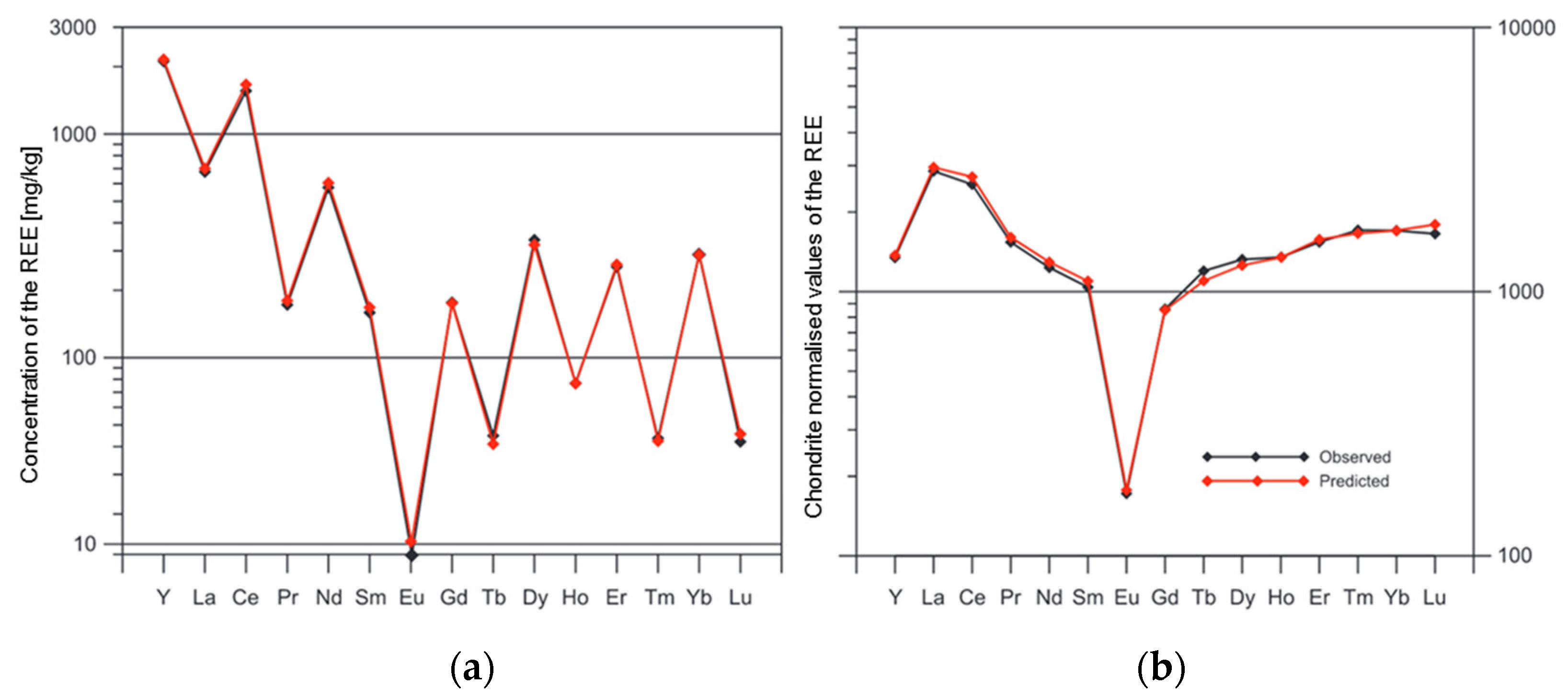
Figure 1. Flow-sheet of the dross processing methods (according to descriptions by Prillhofer et al. [16] and Meshram and Singh [17]).
Metals 11 01108 g001
Figure 2. (a) Plot of the REE mass fractions (except for Sc and Pm) without normalisation and (b) with chondrite normalisation using the example of the “Strange Lake Intrusion” according to Kerr [26].
Metals 11 01108 g002
Figure 3. Representation of: (a) compacted dross and (b) crushed dross pieces.
Metals 11 01108 g003
Figure 4. Process sequence for the melting experiment of the dross with a salt slag in the TBRC.
Metals 11 01108 g004
Figure 5. Mass fractions of the lanthanides in the different phases during the remelting of the dross in the TBRC: (a) chondrite-normalised and (b) normalised to the mass fractions of the metallic aluminium produced.
Metals 11 01108 g005
Table 1. Mass fractions of the REEs (rare earth elements, lanthanides) in chondrites for normalisation in mg/kg (ppm) [24].
ElementYLaCePrNdSmEuGdTbDyHoErTmYbLu
Content1.570.2360.6160.09290.4570.1490.0560.1970.03550.2450.05460.1660.02420.1590.0245
Table 2. Mass balance of the melting experiment in the TBRC.
DesignationFractionsFractions of the Salt SlagMass [kg]
FeedstockDross 35.00
Smelting salt mixture 25.00
Sum input 60.00
ProductsAluminium ingot 26.48
Salt slagSalt slag (including metallic Al and Fe)32.21
Metallic Al > 1 mm1.59
Metallic Al 0.5–1 mm0.48
Fe in salt slag0.16
Salt slag (metallic Al and Fe deducted)29.98
Sum Al output 28.55
Sum output 58.69
Difference (sum input − sum output)1.31
Metal yield I [%] (sum Al output/dross)81.6
Metal yield II [%] (aluminium ingot/dross)75.7
Table 3. REE mass fractions in the different phases in mg/kg (ppm) during dross remelting with salt in the TBRC.
REEDrossMetallic Al (Ingot)SaltSalt Slag
Sc<0.50.18<1<1
Y3.310.281.104.51
La3.020.830.132.85
Ce5.181.210.295.13
Pr0.730.300.0400.61
Nd3.081.290.202.53
Pm----
Sm0.570.110.0600.61
Eu0.530.0020.0350.65
Gd0.450.120.0920.49
Tb0.0870.0350.0150.081
Dy0.390.110.0890.43
Ho0.0630.0100.0160.077
Er0.170.0240.0430.22
Tm0.0230.0030.0070.029
Yb0.180.0040.0450.24
Lu0.0290.0020.0030.034
Σ SEE17.84.52.218.5
Publisher’s Note: MDPI stays neutral with regard to jurisdictional claims in published maps and institutional affiliations.

