Article

Zoning Lubricant Die Application for Improving Formability of Box-Shaped Deep Drawn Parts

by
Wiriyakorn Phanitwong
1,*,
Juksawat Sriborwornmongkol
2 and
Sutasn Thipprakmas
2
1
Department of Industrial Engineering, Rajamangala University of Technology Rattanakosin, Bangkok 10400, Thailand
2
Department of Tool and Materials Engineering, King Mongkut’s University of Technology Thonburi, Bangkok 10400, Thailand
*
Author to whom correspondence should be addressed.
Metals 2021, 11(7), 1015; https://doi.org/10.3390/met11071015
Submission received: 29 March 2021 / Revised: 18 June 2021 / Accepted: 18 June 2021 / Published: 24 June 2021
(This article belongs to the Special Issue Analysis and Design of Metal Forming Processes II)

Abstract

:
The ‘formability’ of sheet metal is a major keyword referring to process design in the sheet metal forming industry. Higher formability could reflect lower production costs and time. Many studies have been carried out to improve formability in various ways, by using the finite element method and experimental approaches. In the present research, a new zoning lubricant technique is proposed. The stainless steel SUS304 square deep drawn box is used as an investigative model. Based on the material flow analysis, we found that zoning lubricant die application could reduce the difference in material flow velocity between wall and corner zones. This material flow characteristic resulted in decreased nonconcurrent plastic deformation during the deep drawing process, as well as decreased stretching in the cup wall and the delaying of the fracture. In the present research, the design of the zoning lubricant die was strictly concerned with achieving functionality related to the friction coefficient, area of zoning, and blank-holder pressure. A smaller friction coefficient positioned in the corner zone and larger friction coefficient positioned in the wall zone are recommended. It was revealed that, by appropriate zoning lubricant die application, formability could be increased in terms of box height by approximately 7 mm or 10%.

1. Introduction

The ‘formability’ of sheet metal is a major keyword used to describe how much plastic deformation a sheet metal can withstand before being damaged. It is an important index for forming process designs to determine the tool shape and the number of forming stations. The increases in formability can support the forming process design by reducing the number of forming stations and increasing the production rate. Many studies have been carried out to increase formability in both simple shape parts, i.e., cylindrical and box shaped parts, and complicated shape parts, i.e., automotive parts. Many studies have been carried out using a heating technique to increase formability [1,2,3,4,5,6,7,8,9,10,11]. Warm deep drawing has been investigated by experimental studies for several kinds of sheet materials, e.g., AZ31B magnesium alloy sheets [4] and HC420LA steel sheets [6]. The new design tool has also been utilized to increase formability [12,13,14,15,16,17,18,19,20,21,22,23,24,25,26,27,28,29]. A new deep drawing process through conical dies based on finite element modeling and experimental studies is proposed to fabricate the brass elliptic cups [14]. The ‘punch with microridges’ technique could be applied to shorten the multistage deep drawing process [18]. Based on this literature and forming theory [30,31,32], the formability of sheet metal is usually explained via forming mechanisms, i.e., material flow and stress distribution analyses. In addition, the formability of sheet metal is dependent on the forming process parameters, i.e., blank-holder pressure, lubricants, and draw radius, as well as the types of shape parts, i.e., cylindrical or box shapes. Setting different forming process parameters results in different forming mechanisms and formability. Setting too-large and too-small blank-holder pressures results in decreased formability [30]. The different shape parts also result in differences in the forming mechanism and formability. To form axisymmetric shape parts, axisymmetric forming mechanisms are generated; conversely, to form nonaxisymmetric shape parts, nonaxisymmetric forming mechanisms are generated. As per the forming theory [30], higher formability can be obtained in the case of axisymmetric shape parts due to the axisymmetric forming mechanisms that are generated. In the past, although many studies were carried out to increase formability, most of them were done without considering different forming mechanisms on each deformation zone during the deep drawing process. Specifically, the forming process parameters were set with the same condition on each different deformation zone. In recent years, research has been focused on setting different process parameters related to the forming mechanism on each deformation zone during the deep drawing process. However, there were a few studies in the past [31,32,33,34] that were performed by setting different draw radii related to the forming mechanism in the cylindrical deep drawing process to increase the limiting drawing ratio (LDR) [32] and to prevent earing defects [31]. Other studies were performed by segmenting blank-holders with pressure control to obtain better formability of deep drawn parts [33,34]. Specifically, lower pressure is applied at the corners; then, on the side wall, control of the process is improved. As per the literature [35,36,37,38,39,40,41], being a major forming process parameter, the lubricant also has a great effect on the forming mechanism and formability. Many techniques of lubricant use in sheet metal fabrication have been developed and applied in a wide range of technologically demanding operations. A selective lubricant using air spray is already employed in sheet metal fabrication; however, this technique is mainly focused on the advantages of controlling the pattern, location, and volume of the lubricant use. Based on this technique and its advantages regarding the different forming mechanisms caused by friction, a new technique for lubricant use was proposed. Based on the different contact surfaces and the lubricant applied, different friction coefficients could be obtained. This technique involves setting a suitable friction coefficient on different die and blank-holder locations related to the forming mechanism, and it is named zoning lubricant die application. Compared with other methods—for example, the aforementioned ‘segment blank-holders with pressure control’ method—the proposed zoning lubricant die application has advantages including simple tool design and manufacture, no need for additional equipment, and a low tool cost.
By using this technique on a square box shape, in the present research, formability in terms of box height could be increased by approximately 10%. Based on this obtained knowledge, this technique could be applied in industrial settings to increase the formability of complicated shape parts, e.g., automotive and aerospace parts.

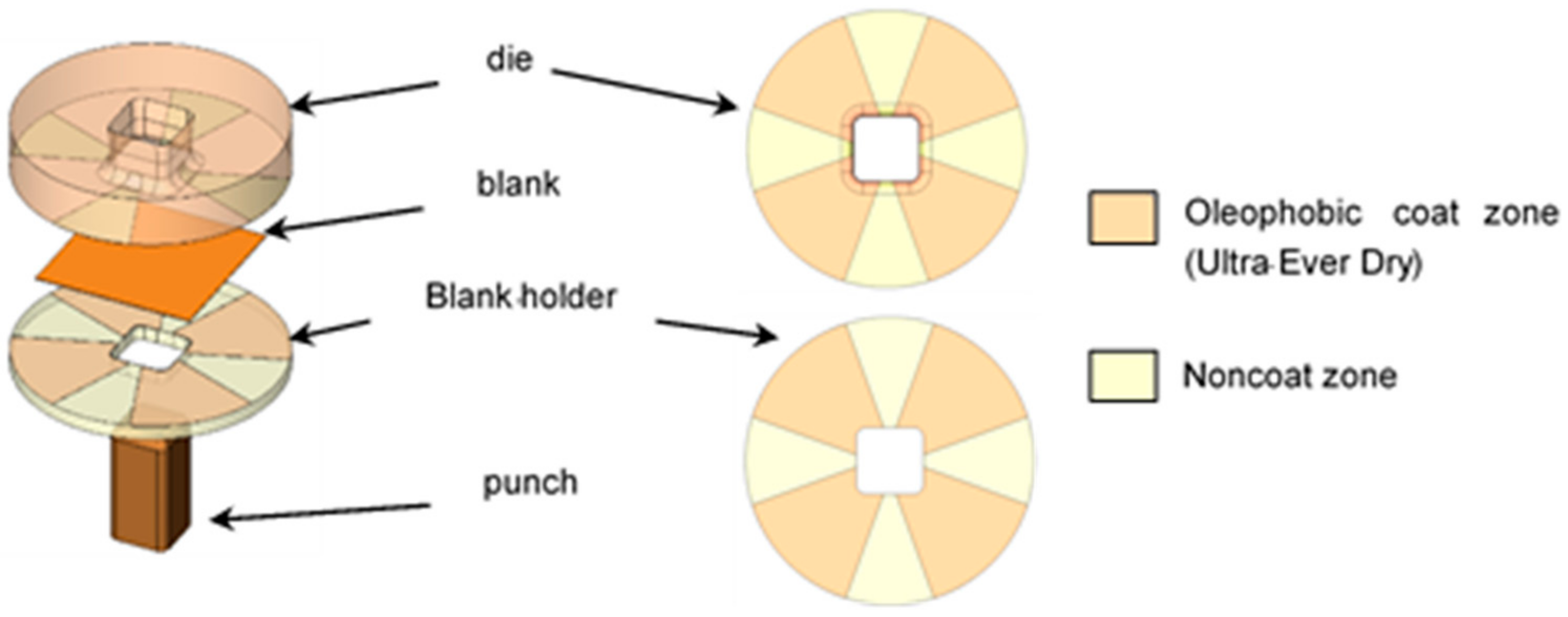
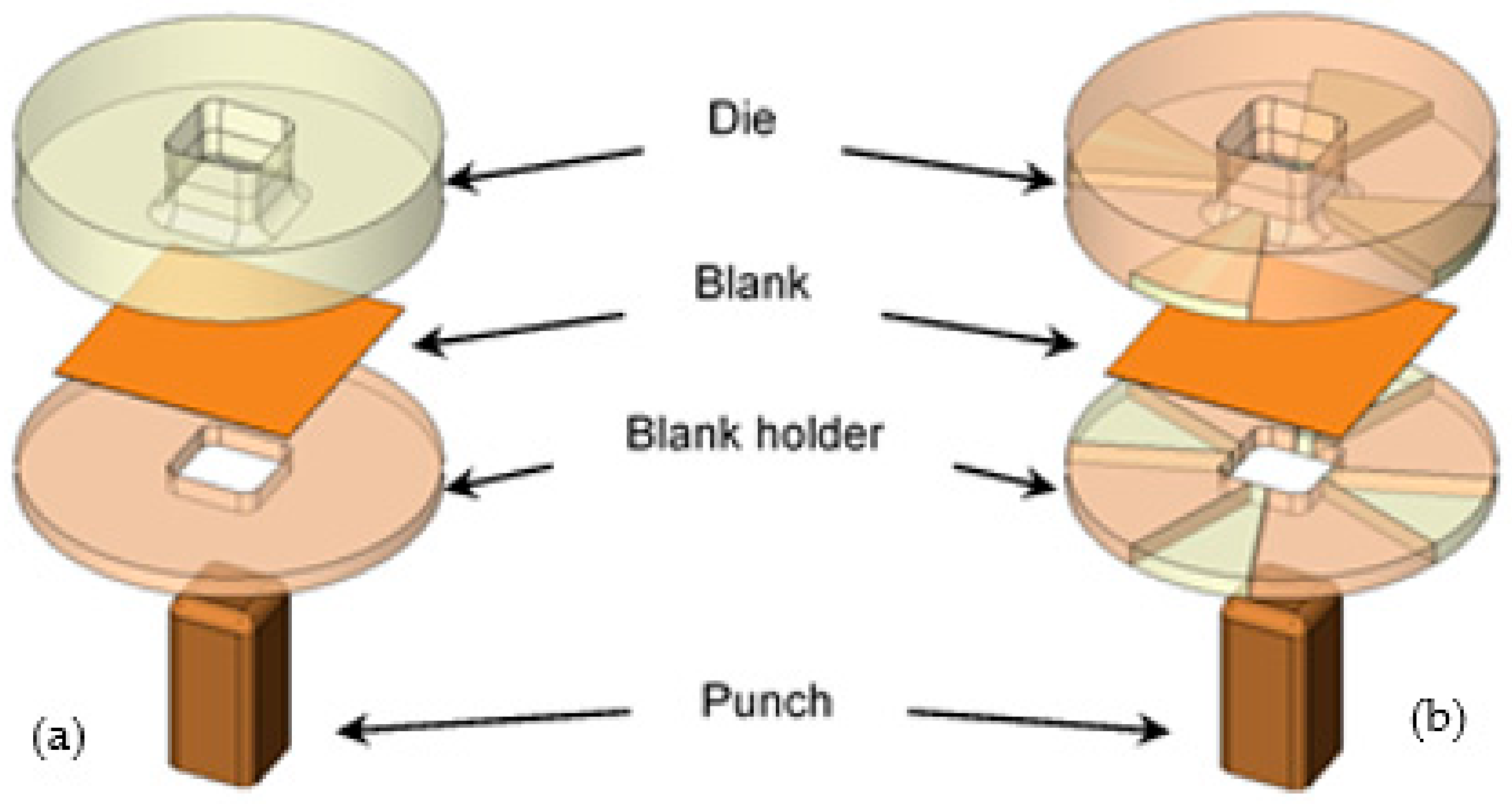
2. Proposed Zoning Lubricant Deep Drawn Die Application and Its Principles

As per the deep drawing theory [30], lubricant use commonly affects formability in the deep drawing process. Via the friction coefficient, frictional shear stress is generated during the deep drawing process with respect to various kinds of lubricant uses. This frictional shear stress directly affects the deep drawing mechanism based on the material flow and stress distribution, as shown in Figure 1. The material moving into the die occurs earlier in the wall zone and later in the corner zone. In the wall zone (section B–B), as shown in Figure 1d, as the displacement in the radial direction is very small, the deformation becomes almost plane strain elongated. On the other hand, in the corner zone (section A–A), as shown in Figure 1c, material at the flange portion flows inwards and must shrink in a circular direction. Therefore, in this region, indirect compression in the circular direction is dominant. By tension in the radial direction, material is indirectly compressed in the circular direction. Over the die radius, the deformation of material varies drastically from near-pure-shear to near-plane-strain elongation by bending with shrinking flange deformation. Thus, based on this compressive stress generated in the circular direction, the frictional shear stress generated in the corner zone is higher than that generated in the wall zone. Nonconcurrent plastic deformation was also generated and caused the restriction of material flown into the die. Based on these material flow characteristics, the cup wall stretching and fracture could be more easily formed. This deep drawing mechanism is a major barrier for increases in formability. In the present research, to decrease the nonconcurrent plastic deformation during the deep drawing process, the zoning lubricant die application is proposed. This was performed by using a lower friction coefficient lubricant in the corner zone to decrease the frictional shear stress generated on this zone, while the lubricant with a higher friction coefficient was applied to the wall zone, as shown in Figure 1a. By using this technique, the frictional shear stress generated at the corner zone is decreased and the nonconcurrent plastic deformation, being a restriction of formability, is decreased as well. These result in the increases in formability.
In the present research, as the first step to investigate the zoning lubricant die application based on the abovementioned principle, an oleophobic coat was applied as an oil-repellent coating to obtain the lower friction coefficient. The laboratory tool was designed by segmenting the four wall zones and four corner zones on the blank-holder and die, as shown in Figure 2. Next, the oleophobic coat was applied only on the four corner zones. By applying a form of lubricant during deep drawing, the friction coefficient was made to differ between the wall and corner zones; a lower friction coefficient at the corner zone and higher friction coefficient at the wall zone could be obtained.

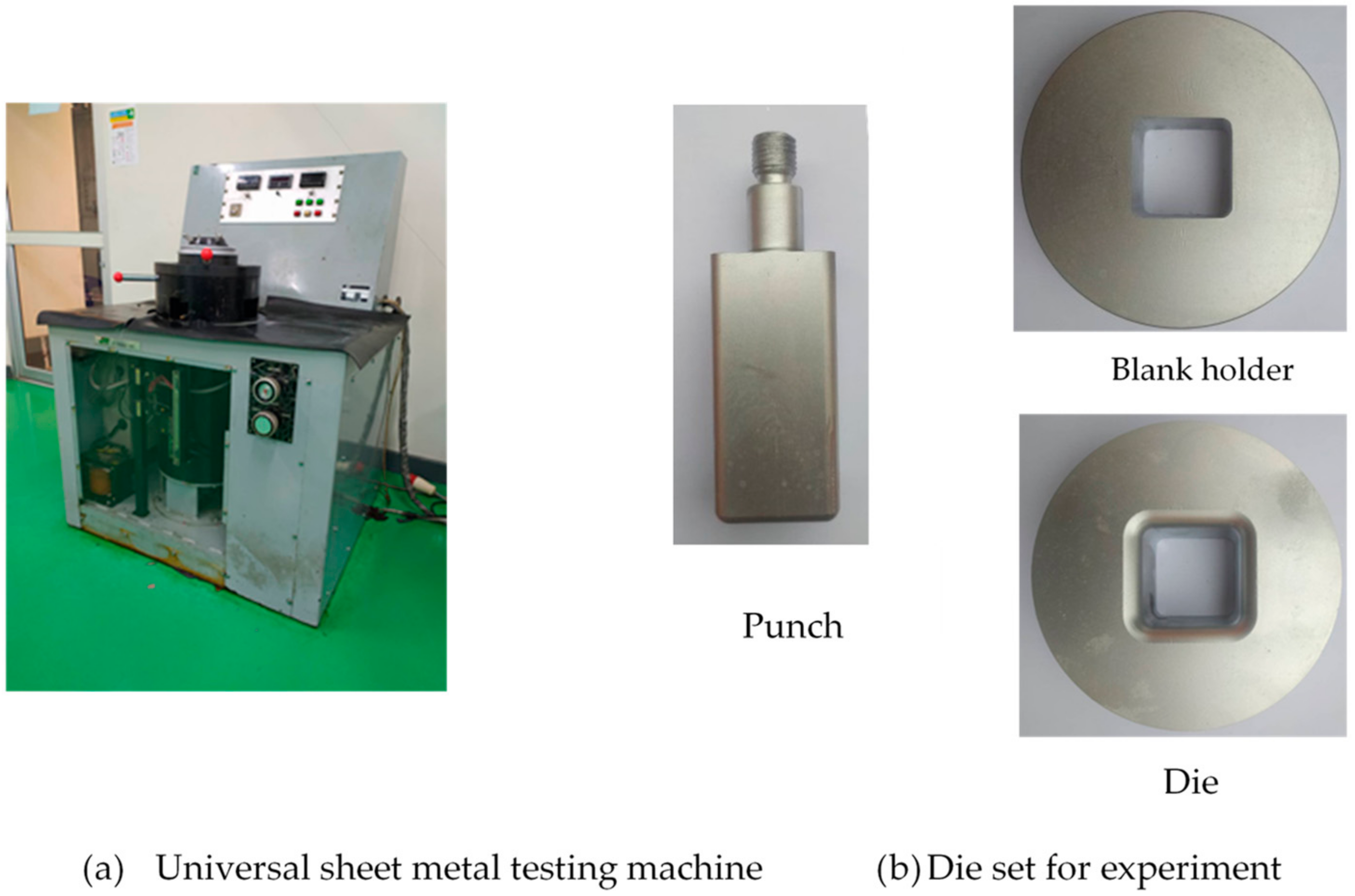
3. FEM Simulation and Experimental Procedures

In the present research, the FEM simulation was used as a tool to clarify the square deep drawing mechanism of zoning lubricant die application based on the material flow and strain distribution analyses. The nonlinear FEM commercial code HyperForm 14.0 with RADIOSS script (Altair Engineering, Inc., Troy, MI, USA) as the solver was used for FEM simulation of the deep drawing process. The investigated model of zoning lubricant die application is shown in Figure 3b. In addition, in order to understand the deep drawing mechanism of zoning lubricant die application, the deep drawing mechanism of conventional die application was also investigated based on the model shown in Figure 3a. These 3-D square deep drawing models were created by Cimatron 3 (3D Systems, Inc., Givat Shmuel, Israel), then imported as an IGES file into HyperForm. The HyperMesh preprocessor was used to create the mesh. The details of the FEM simulation and experiments are listed in Table 1. The initial blank was set as elastoplastic and meshed into finite elements of the “shell”-type. The 4-node quadrilateral shape elements of approximately 3500 elements were generated. The adaptive remeshing was also set. After remeshing, to produce smooth meshes, a combination of 4-node quadrilateral shape elements and triangular shape elements was generated. The tools, including punch, die, and blank-holder, were meshed with the rigid mesh type to prevent their deformation during the deep drawing process. Blank-holder forces of 3 kN and 70 kN were applied. In the present research, the forming limit diagram (FLD) was used to clarify the forming characteristics and to predict the fracture zone on square deep drawn parts. The workpiece used in this present research was stainless steel grade SUS304 (JIS standard) with a thickness of 0.5 mm. The material properties of the flow curve equation and plastic strain ratio (R-value) were prepared as input parameters for FEM simulation. The workpiece material was described with an elastoplastic, power exponent, isotropic-plasticity model of the Hollomon power law hardening model, with the constitutive equation determined from the stress–strain curve using the tensile test data. The specimens were prepared according to the Specimen No. JIS 13B as specified in JIS Z 2201:1998 standard and the tensile tests were performed following the JIS Z 2241:2011 standard. The obtained engineering stress–strain relationship is shown in Figure 4a and the true stress-strain curve are calculated and shown in Figure 4b. As listed in Table 1, the strength coefficient and strain hardening exponent were 1209.4 MPa and 0.38, respectively. The other necessary material properties, such as the Young’s modulus, Poisson’s ratio, and ultimate tensile strength, are also given in Table 1. In the present research, based on the deep drawing process with lubricant, the contact surface model was defined by a Coulomb friction law, and friction coefficients (µ) of 0.03 and 0.10 were applied. Next, a clearance of 0.5 mm was set. The tool radius for the conventional die was set following the deep drawing theory [27], namely, a punch radius of 8.0 mm and die radius of 8.0 mm were set. The initial blank size of 100 mm in a square shape was used.
To characterize and find out the friction coefficients between rigid friction pairs, in the present research, the commonly used ball-on-disc tribology tests were applied. The ball was positioned perpendicular to the disc fixed on a rotating plate. The friction coefficient between the ball and the disc could thus be determined. The stainless-steel sheet grade SUS304 (JIS) was applied as a disc, and the ball material was of tool steel grade SKD11 (JIS). The stainless steel SUS304 disc of 20 mm in diameter and tool steel SKD11 ball 6 mm in diameter were applied. A ball-on-disc tribometer (Anton paar Co., Ltd., Buchs, Switzerland) was used. In the present research, ball-on-disc tribology tests were carried out under the two conditions of conventional lubricant and oleophobic coat. The conventional lubricant used was Iloform TDN81 (Castrol Limited, Berkshire, UK) and the oleophobic coat used was Ultra-Ever Dry (Ultra-Ever dry-store.eu., Liberec, Czech Republic). The chemical compositions of the oleophobic coating (Ultra-Ever Dry) are listed in Table 2. In the case of conventional lubricant use, Iloform TDN 81 was continuously fed as the ball slid on the disc. In the case of oleo-phobic coating use, first, the oleophobic coated blank sheet was prepared and used as the disc. It was prepared by coating two layers of the bottom and top coats with an overall thickness of approximately 30 µm. Again, as the ball slid on this disc, the Ilo-form TDN 81 was continuously fed. The normal forces of 5 N were examined. The examined sliding distance of approximately 50 m was implemented. The other details of testing conditions are listed in Table 3.
Laboratory experiments were performed to validate the FEM simulation results. Figure 5 shows the press machine, which includes a universal sheet metal testing machine (Model SAS-350D, JT Toshi Inc., Minato-ku, Japan) and the sets of deep drawing die applications. The blank anisotropy affects the fracture location; this is controlled in the experiments. The orientation of the blank is not altered for different tests to change the direction of anisotropy. The obtained deep drawn parts were sectioned by a wire electrical discharge machine for cup wall thickness examination. Five samples from each deep drawing condition were used to inspect the obtained deep drawn parts. The thicknesses in the wall and corner zones were calculated based on these obtained deep drawn parts. The measurement results in the wall zone and corner zone refer to the average of the four wall zones and four corner zones, respectively. These average thickness values in the wall and corner zones were reported and compared with those analyzed by the FEM simulation.

4. Results and Discussion

4.1. Friction Coefficient Examinations

Figure 6 shows the comparison of the obtained friction coefficients in the cases of a conventional lubricant (Iloform TDN81) and oleophobic coat with Iloform TDN81 lubricant. A higher friction coefficient was obtained in the case of conventional lubricant use. The results show that the friction coefficient was approximately 0.10, as shown in Figure 6a. In the case of the oleophobic coat shown in Figure 6b, on the basis of an oil repellent coating, the friction coefficient was lower; it was approximately 0.03 in the first sliding distance of 30 m and increased to approximately 0.10 after another slide with a distance of 30 m. This could be explained by the limited adhesive ability of the oleophobic coat. It is noteworthy that the friction coefficient could be very small when the oleophobic coating is applied. These results would be useful for applications in sheet-metal forming processes in which the friction coefficient has great effects on formability.

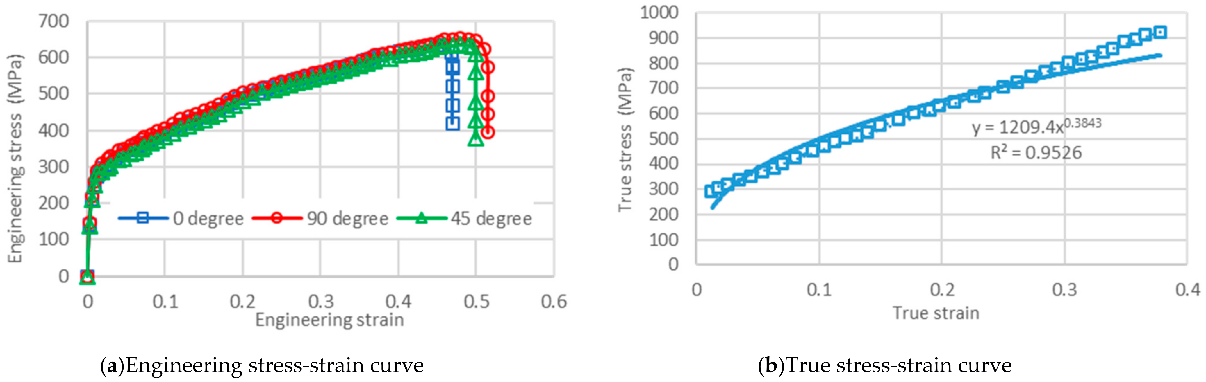
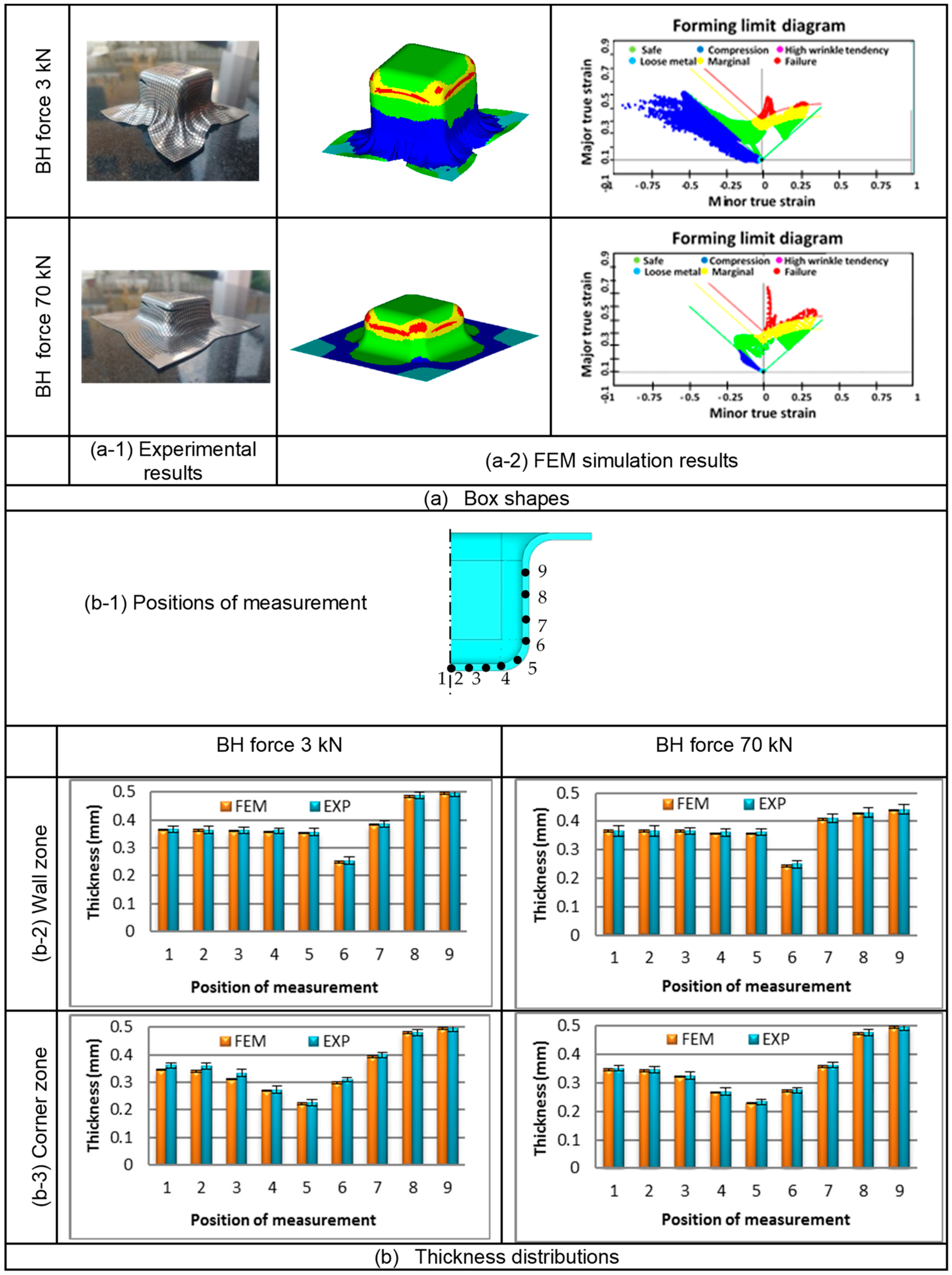
4.2. Validation of FEM Simulation Use

The accuracy of the FEM simulation results should be validated before starting the discussion section of the FEM simulation results. Based on the conventional die and lubrication conditions, as the validation of the FEM simulation results shown in Figure 7 by comparison with the laboratory experiments, the deep drawn parts correspond well with the experiments. The FEM simulation result corresponds well with the experiments in both cases of blank-holder force 3 kN and 70 kN. Based on the FLD, the fracture was generated in the bottom corner zone and a circumferential character was formed, which agreed well with the fracture generated on the deep drawn part obtained by the experiment. In terms of formability based on box height limitation, the box heights in the cases of blank-holder forces of 3 kN and 70 kN were limited to approximately 35 mm and 20 mm, respectively. These results also agreed well with the theory behind the deep drawing process, in which the formability decreased as the too-large blank-holder pressure was applied. The wall thickness was also examined. The comparisons of wall thickness distribution between FEM simulation and experimental results are illustrated in Figure 7. The FEM simulation results showed that the predicted wall thickness distributions correspond well with the experiments, in which the errors in the analyzed wall thickness were approximately 3% compared with the experimental results.

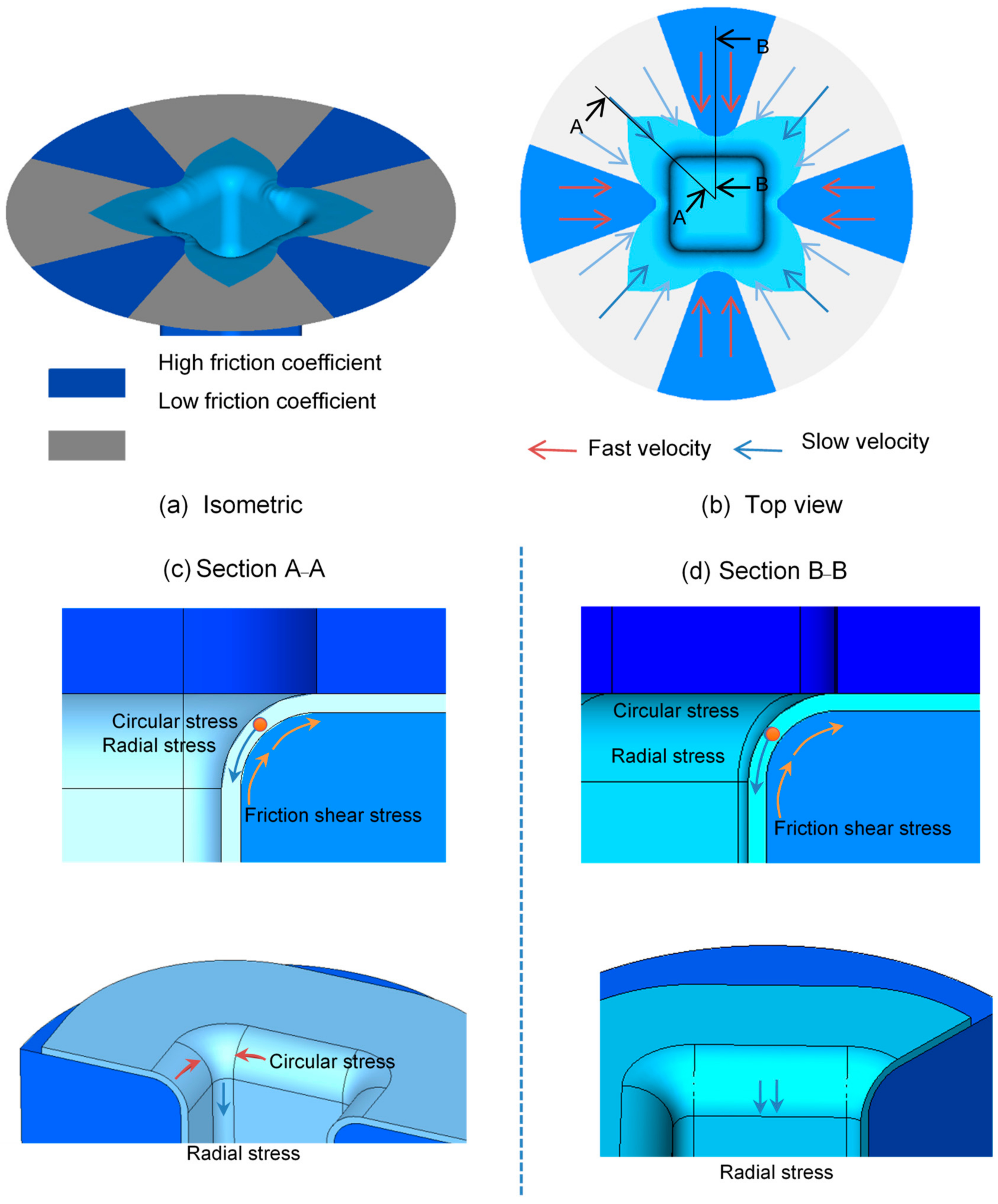
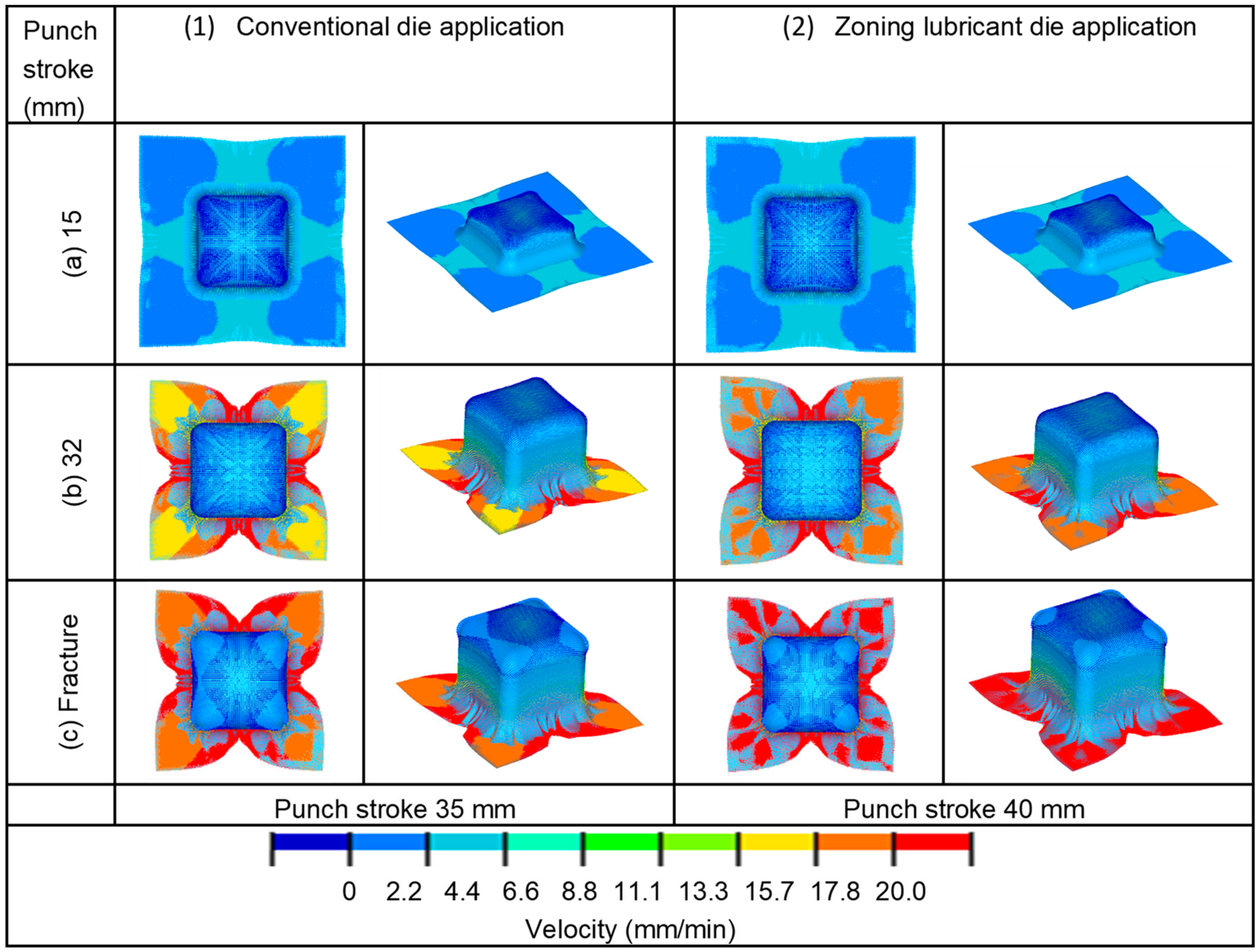
4.3. Comparison of Material Flow Analysis between Conventional and Zoning Lubricant Deep Drawing Die Applications

The aforementioned principle of zoning lubricant die application was characterized based on the material flow obtained by the FEM simulation. The comparison of material flow analysis between conventional and zoning lubricant die applications is illustrated in Figure 8. The same manner of material flow analysis was illustrated at the beginning of the deep drawing process. At the deep drawing stroke of approximately 15 mm, shown in Figure 8a, higher material flow velocity formed at the wall zone while lower material flow velocity formed at the corner zone in both cases of conventional and zoning lubricant die applications. These results correspond well with the theory behind the deep drawing process [27]. It was also observed that the material flow velocity generated at the wall and corner zones in the case of conventional die application were the same level as those generated in the case of zoning lubricant die application. Material flow velocities of approximately 7 mm/s and 2 mm/s were generated at the wall and corner zones, respectively. As the deep drawing stroke increased, this difference in material flow characteristic between conventional and zoning lubricant die applications became more evident, as shown in Figure 8b. Furthermore, the FEM simulation also showed the difference in material flow velocity at the wall and corner zones in the case of conventional die application, as shown in Figure 8(b1). A material flow velocity of approximately 20 mm/s was generated at the wall zone, whereas a material flow velocity of approximately 14 mm/s was generated at the corner zone. This material flow characteristic resulted in nonconcurrent plastic deformation and easily formed fractures. By contrast, in the case of zoning lubricant die ap-plication shown in Figure 8(b2), the FEM simulation results showed a material flow velocity of approximately 20 mm/s generated at the wall zone. This velocity is similar to that generated in the case of conventional die application. However, the FEM simulation results also showed that by comparison with the case of conventional die application, the material flow velocity at the corner zone, which was approximately 17 mm/s, could be increased. This could be explained by the fact that due to the applied oleophobic coat at the corner zone, a low friction coefficient was generated, and the frictional shear stress generated at this zone was lower than that generated in the case of conventional die application; thus, the material flow velocity at the corner zone could be increased. Based on these material flow characteristics, the nonconcurrent plastic deformation could be reduced by using zoning lubricant die application and the fracture could be delayed. Next, as the deep drawing stroke increased, as shown in Figure 8c, the FEM simulation results showed that formability based on box height in the case of conventional die application was limited to approximately 35 mm, as shown in Figure 8(c1). Conversely, owing to the aforementioned decreases in nonconcurrent plastic deformation, a higher box height could be achieved. The FEM simulation results showed that the box height was limited to approximately 40 mm in the case of zoning lubricant die applications, as shown in Figure 8(c2). These FEM simulation results revealed that, with zoning lubricant die application, the various friction coefficients applied by the zoning lubricant die had great effects on the material flow characteristic. The smaller friction coefficient could generate increases in material flow velocity during the deep drawing process, and then the nonconcurrent plastic deformation could be reduced. Based on these material flow characteristics, the fracture could be delayed and formability could be increased.

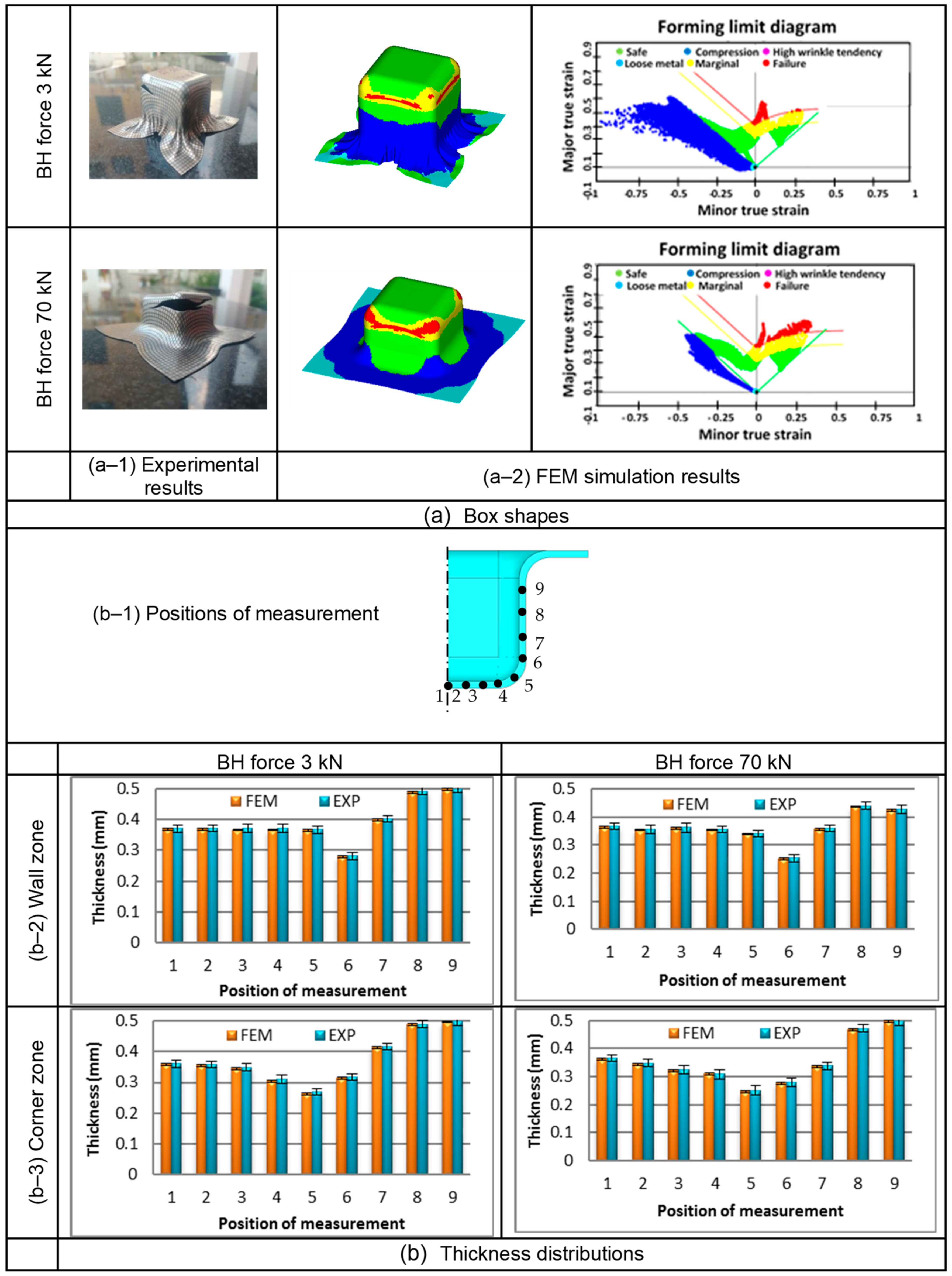
4.4. Confirmation of Zoning Lubricant Die Application

To confirm the use of zoning lubricant die application and validate the accuracy of the FEM simulation use, the FEM simulation results were compared with those obtained by experimental results, as shown in Figure 9. The FEM simulation results showed that the predicted deep drawn parts corresponded well with the experiments. In addition, the FEM simulation results also showed the fracture, which corresponded well with the experimental results. On the basis of FLD, the fracture was again generated at the corner zone and a circumferential character was formed that agreed well with the fracture generated on the deep drawn part obtained by the experiment. In terms of wall thickness, the FEM simulation results showed that the predicted cup wall thickness corresponded well with the experiments as well, in which the errors in the analyzed cup wall thickness were approximately 3% compared to the experimental results. Again, in terms of formability based on box height limitation, the box heights in the cases of blank-holder forces of 3 kN and 70 kN were limited to approximately 40 mm and 26 mm, respectively, by zoning lubricant die application. By comparison with the results obtained by conventional die application shown in Figure 7, these results indicate that an increase in the formability of box height limitation of approximately 10% could be achieved. Next, it was observed that the same cup wall thickness distribution as conventional lubricant use was obtained, as shown Figure 7b and Figure 9b. This could be explained by the fact that these cup wall thickness distributions were reported based on the different box heights at fracture. Based on the principle of zoning lubricant die application being able to reduce the friction resistance of the corner zone and increase the material flow rate, at the same box height, the cup wall thinning should be decreased compared with that obtained from conventional lubricant use. However, by comparing them at the fracture stage, the same cup wall thickness distribution was obtained due to it thinning with the increases in box height.

5. Conclusions

To increase formability during the square deep drawing process, zoning lubricant die application was proposed in the present research. First, based on the material flow analysis, the conceptual design of zoning lubricant die application was proposed, and its principle was also elucidated by FEM simulations. The absolute validation of FEM simulation use was also performed. By using zoning lubricant die application, it was revealed that the material flow velocity at wall and corner zones could obtain more balance and concurrent plastic deformation could be achieved. Specifically, during the deep drawing process, zoning lubricant die application could reduce the frictional shear stress at the corner zone, and the material flow velocity at this zone could be effectively increased, meaning a more concurrent plastic deformation could be obtained. Therefore, cup wall stretching could be reduced and the fracture could be delayed. Based on this material flow characteristic, formability could be increased. The results of the present research revealed that formability in terms of box height could be increased by approximately 10% using zoning lubricant die application. However, proper zoning lubricant die design related to the friction coefficient, area of zoning, and blank-holder pressure should be strictly considered. A smaller friction coefficient positioned at the corner zone and larger friction coefficient positioned at the wall zone are recommended.

Author Contributions

Conceptualization, W.P. and S.T.; methodology, W.P. and S.T.; software, W.P.; validation, W.P., J.S. and S.T.; formal analysis, W.P. and S.T.; investigation, W.P. and J.S.; resources, W.P. and S.T.; data curation, W.P., J.S. and S.T.; writing—original draft preparation, J.S.; writing—review and editing, W.P. and S.T.; visualization, W.P. and S.T.; supervision, S.T.; project administration, W.P.; funding acquisition, W.P. All authors have read and agreed to the published version of the manuscript.

Funding

This research was supported by a grant from (1) Rajamangala University of Technology under Grant No. C-37/2563; (2) The Thailand Research Fund (TRF) and Rajamangala University of Technology Rattanakosin under Grant No. MRG6280205 and (3) Department of Tool and Materi-als Engineering, King Mongkut’s University of Technology Thonburi.

Institutional Review Board Statement

Not applicable.

Informed Consent Statement

Not applicable.

Data Availability Statement

Not applicable.

Acknowledgments

The authors would like to express their gratitude to Kampanart Sirindhorn, International Thai-German Graduate School of Engineering, King Mongkut’s University of Technology North Bangkok, for their support in the tribology tests. We would also like to express our gratitude to Arkarapon Sontamino, Department of Mechanical Engineering Technology, College of Industrial Technology, King Mongkut’s University of Technology North Bangkok, for his experimental support in this research.

Conflicts of Interest

The authors declare no conflict of interest.

References

  1. Ouyang, Y.; Lee, M.S.; Moon, J.H.; Kang, C.G. The effect of the blank holding force on formability in hot deep drawing of boron steel considering heat transfer phenomena and friction coefficient by simulation and experimental investigation. Proc. Inst. Mech. Eng. Part B J. Eng. Manuf. 2012, 226, 1506–1518. [Google Scholar] [CrossRef]
  2. Behrens, G.; Trier, F.O.; Tetzel, H.; Vollertsen, F. Influence of tool geometry variations on the limiting drawing ratio in micro deep drawing. Int. J. Mater. Form. 2016, 9, 253–258. [Google Scholar] [CrossRef]
  3. Kayhan, E.; Kaftanoglu, B. Experimental investigation of non-isothermal deep drawing of DP600 steel. Int. J. Adv. Manuf. Technol. 2018, 99, 695–706. [Google Scholar] [CrossRef]
  4. Wang, W.; Chen, S.; Tao, K.; Gao, K.; Wei, X. Experimental investigation of limit drawing ratio for AZ31B magnesium alloy sheet in warm stamping. Int. J. Adv. Manuf. Technol. 2017, 92, 723–731. [Google Scholar] [CrossRef]
  5. Satish, D.R.; Kumar, D.R. Formability of AA6061 alloy sheets in warm forming temperature range. Proc. Inst. Mech. Eng. Part L J. Mater. Des. Appl. 2019, 233, 413–425. [Google Scholar] [CrossRef]
  6. Şen, N.; Karaağaç, İ.; Kurgan, N. Experimental research on warm deep drawing of HC420LA grade sheet material. Int. J. Adv. Manuf. Technol. 2016, 87, 3359–3371. [Google Scholar] [CrossRef]
  7. Panicker, S.S.; Panda, S.K. Improvement in material flow during nonisothermal warm deep drawing of nonheat treatable aluminum alloy sheets. J. Manuf. Sci. Eng. 2017, 139, 031013. [Google Scholar] [CrossRef]
  8. Fallahiarezoodar, A.; Peker, R.; Altan, T. Temperature increase in forming of advanced high-strength steels effect of ram speed using a servodrive press. J. Manuf. Sci. Eng. 2016, 138, 094503. [Google Scholar] [CrossRef]
  9. Meza-García, E.; Birnbaum, P.; Landgraf, P.; Grund, T.; Lampke, T.; Kräusel, V. Thermomechanical treatment of martensitic stainless steels sheets and its effects on their deep drawability and resulting hardness in press hardening. Metals 2020, 10, 1536. [Google Scholar] [CrossRef]
  10. Yuan, S.; Cheng, W.; Liu, W.; Xu, Y. A novel deep drawing process for aluminum alloy sheets at cryogenic temperatures. J. Mater. Process. Technol. 2020, 284, 116743. [Google Scholar] [CrossRef]
  11. Wang, M.; Li, J.; Deng, L.; Li, J. Metal flow control during hot forming of square cups with local-thickened plates and varied friction conditions. J. Mater. Process. Technol. 2018, 253, 195–203. [Google Scholar] [CrossRef]
  12. Phanitwong, W.; Thipprakmas, S. Parameter design of draw bead in rectangular deep-drawing process using Taguchi technique. Steel Res. Int. 2012, 379–382. [Google Scholar]
  13. Vasudevan, V.; Bandyopadhyay, K.; Panda, S.K. Influence of anisotropy parameter on deep drawing of tailor welded blanks of low-carbon steels. Proc. Inst. Mech. Eng. Part B J. Eng. Manuf. 2014, 228, 1162–1171. [Google Scholar] [CrossRef]
  14. Dhaiban, A.A.; Soliman, M.E.S.; El-Sebaie, M. Finite element modeling and experimental results of brass elliptic cups using a new deep drawing process through conical dies. J. Mater. Process. Technol. 2014, 214, 828–838. [Google Scholar] [CrossRef]
  15. Karajibani, E.; Hashemi, R.; Sedighi, M. Determination of forming limit curve in two-layer metallic sheets using the finite element simulation. Proc. Inst. Mech. Eng. Part L J. Mater. Des. Appl. 2016, 230, 1018–1029. [Google Scholar] [CrossRef]
  16. Martins, A.L.T.; Couto, A.A.; Lima, N.B. Study of the deep drawing behavior and crystallographic texture of AA 3104-H19 aluminum alloy sheets. Proc. Inst. Mech. Eng. Part L J. Mater. Des. Appl. 2016, 230, 748–759. [Google Scholar] [CrossRef]
  17. Kesharwani, R.K.; Basak, S.; Panda, S.; Pal, S. Improvement in limiting drawing ratio of aluminum tailored friction stir welded blanks using modified conical tractrix die. J. Manuf. Process. 2017, 28, 137–155. [Google Scholar] [CrossRef]
  18. Lin, B.T.; Yang, C.Y. Using a punch with micro-ridges to shorten the multistage deep drawing process for stainless steels. Int. J. Adv. Manuf. Technol. 2017, 88, 2693–2703. [Google Scholar] [CrossRef]
  19. Jalil, A.; Gollo, M.H.; Seyedkashi, S.M.H. Process analysis of hydrodynamic deep drawing of cone cups assisted by radial pressure. Proc. Inst. Mech. Eng. Part B J. Eng. Manuf. 2017, 231, 1793–1802. [Google Scholar] [CrossRef]
  20. Magrinho, J.P.G.; Silva, C.M.A.; Silva, M.B.; Martins, P.A.F. Formability limits by wrinkling in sheet metal forming. Proc. Inst. Mech. Eng. Part L J. Mater. Des. Appl. 2018, 232, 681–692. [Google Scholar] [CrossRef]
  21. Zhang, C.B.; Gong, F. Deep drawing of cylindrical cups using polymer powder medium based flexible forming. Int. J. Precis. Eng. Manuf. Green Technol. 2018, 5, 63–70. [Google Scholar] [CrossRef]
  22. Abe, Y.; Mori, K.I.; Maeno, T.; Ishihara, S.; Kato, Y. Improvement of sheet metal formability by local work-hardening with punch indentation. Prod. Eng. 2019, 13, 589–597. [Google Scholar] [CrossRef]
  23. Lee, M.S.; Kim, S.J.; Seo, H.Y.; Kang, C.G. Investigation of formability and fiber orientation in the square deep dawing process with Steel/CFRP hybrid composites. Int. J. Precis. Eng. Manuf. Green Technol. 2019, 20, 2019–2031. [Google Scholar] [CrossRef]
  24. Fazlollahi, M.; Morovvati, M.R.; Dariani, B.M. Theoretical, numerical and experimental investigation of hydro-mechanical deep drawing of steel/polymer/steel sandwich sheets. Proc. Inst. Mech. Eng. Part B J. Eng. Manuf. 2019, 232, 1529–1546. [Google Scholar] [CrossRef]
  25. Ballikaya, H.; Savas, V.; Ozay, C. The limit drawing ratio in die angled hydromechanical deep drawing method. Int. J. Adv. Manuf. Technol. 2020, 106, 791–801. [Google Scholar] [CrossRef]
  26. Hajiahmadi, S.; Elyasi, M. Evaluation of drawing force by a new dimensionless method in deep drawing process. Proc. Inst. Mech. Eng. Part B J. Eng. Manuf. 2020, 234, 1604–1614. [Google Scholar] [CrossRef]
  27. Moghadam, M.; Nielsen, C.V.; Bay, N. Analysis of the risk of galling in sheet metal stamping dies with drawbeads. Proc. Inst. Mech. Eng. Part B J. Eng. Manuf. 2020, 234, 1207–1214. [Google Scholar] [CrossRef]
  28. Tan, C.J.; Aslian, A. FE simulation study of deep drawing process of SUS304 cups having no delayed cracks under enhanced blank holding force. Proc. Inst. Mech. Eng. Part B J. Eng. Manuf. 2020, 234, 84–94. [Google Scholar] [CrossRef]
  29. Iorio, L.; Pagani, L.; Strano, M.; Monno, M. Design of Deformable Tools for Sheet Metal Forming. J. Manuf. Sci. Eng. 2016, 138, 094701. [Google Scholar] [CrossRef]
  30. Lange, K. Handbook of Metal Forming; McGraw-Hill Inc.: New York, NY, USA, 1985; Chapter 20; ISBN 978-0070362857. [Google Scholar]
  31. Jankree, R.; Thipprakmas, S. Achievements of nearly zero earing defects on SPCC cylindrical drawn cup using multi draw radius die. Metals 2020, 10, 1204. [Google Scholar] [CrossRef]
  32. Phanitwong, W.; Thipprakmas, S. Multi draw radius die design for increases in limiting drawing ratio. Metals 2020, 10, 870. [Google Scholar] [CrossRef]
  33. Zhang, H.; Qin, S.; Cao, L.; Meng, L.; Zhang, Q.; Li, C. Research on deep drawing process using radial segmental blank holder based on electro-permanent magnet technology. J. Manuf. Process. 2020, 59, 636–648. [Google Scholar] [CrossRef]
  34. Hassan, M.A.; Takakaru, N.; Yamaguchi, K. Friction aided deep drawing using newly developed blank-holder divided into eight segments. Int. J. Mach. Tools Manuf. 2003, 43, 637–646. [Google Scholar] [CrossRef]
  35. Krachenfels, K.; Rothammer, B.; Tremmel, S.; Merklein, M. Experimental investigation of tool-sided surface modification for dry deep drawing processes at the tool radii area. Procedia Manuf. 2019, 29, 201–208. [Google Scholar] [CrossRef]
  36. Dilmec, M.; Arap, M. Effect of geometrical and process parameters on coefficient of friction in deep drawing process at the flange and the radius regions. Int. J. Adv. Manuf. Technol. 2016, 86, 747–759. [Google Scholar] [CrossRef]
  37. Tan, C.J.; Ibrahim, M.S.; Muhamad, M.R. Preventing delayed cracks in SUS304 deep drawn cups using extreme blank holding forces aided by nanolubrication. Int. J. Adv. Manuf. Technol. 2019, 100, 1341–1354. [Google Scholar] [CrossRef]
  38. Yun, S.; Jung, J.; Jun, S.; Jeong, J.; Moon, Y.H.; Kim, J.H. Constitutive and fracture modeling of biaxially oriented polyethylene terephthalate film and its application to polymer-coated sheet metal forming. J. Manuf. Sci. Eng. 2020, 143, 061005. [Google Scholar] [CrossRef]
  39. Tomáš, M.; Evin, E.; Kepiˇc, J.; Hudák, J. Physical modelling and numerical simulation of the deep drawing process of a box-shaped product focused on material limits determination. Metals 2019, 9, 1058. [Google Scholar] [CrossRef] [Green Version]
  40. Trzepiecinski, T. A Study of the coefficient of friction in steel sheets forming. Metals 2019, 9, 988. [Google Scholar] [CrossRef] [Green Version]
  41. Shisode, M.; Hazrati, J.; Mishra, T.; Rooij, M.D.; Boogaard, T.V.D. Mixed lubrication friction model including surface texture effects for sheet metal forming. J. Mater. Process. Technol. 2021, 291, 117035. [Google Scholar] [CrossRef]
Figure 1. Material flow characteristics and stress distribution analysis during the deep drawing process.
Metals 11 01015 g001
Figure 2. Proposed zoning lubricant die application.
Metals 11 01015 g002
Figure 3. FEM simulation models, (a) Conventional die (Nonzoning lubricant) and (b) Zoning lubricant die.
Metals 11 01015 g003
Figure 4. Engineering stress–strain and true stress-strain curve curves of SUS304.
Metals 11 01015 g004
Figure 5. Testing machine and die set for experiment.
Metals 11 01015 g005
Figure 6. Illustration of friction coefficients with respect to lubricant and coating use.
Metals 11 01015 g006
Figure 7. Comparisons of box shapes and thickness distributions obtained by FEM simulation and experimental results.
Metals 11 01015 g007
Figure 8. Comparisons of material flow analysis between conventional die and zoning lubricant die applications (blank-holder force, 3 kN).
Metals 11 01015 g008
Figure 9. Confirmation of the use of zoning lubricant die applications.
Metals 11 01015 g009
Table 1. FEM simulation and experimental conditions.
Tool GeometryPunch: Punch 40.0 mm × 40.0 mm, Punch radius 8.0 mm
Die: Die 42.0 mm × 42.0 mm, Die radius 8.0 mm
Clearance0.5 mm
Punch speed30 mm/min
Blank-holder force3 and 70 kN
Blank size100 mm × 100 mm
Thickness (t)0.5 mm
Sheet material:
Stainless steel (SUS304)
Tensile strength627.1 MPa
Yield strength 283.8 MPa
Elongation47.2%
Young’s modulus190 GPa
Poisson ratio0.3
Constitutive equation σ = 1209.4 ε 0.38
Plastic strain ratio0°:0.985
45°:1.209
90°:1.055
LubricantConventional Lubricant (Ilofom, TDN81): μ = 0.10
Oleophobic coat (Ultra-Ever Dry): μ = 0.03
Table 2. Chemical compositions of oleophobic coating (Ultra-Ever Dry).
Bottom Coat (wt%)Top Coat (wt%)
Xylenes36Acetone96–98
t-Butyl Acetate36Silica2–4
Acetone11Proprietary Additive1
Proprietary Polymer16--
Proprietary Additives1--
Table 3. Tribology test conditions.
Test ConditionDisc dimension20 mm (dia)
Linear Speed21 cm/s
Acquisition rate50.0 Hz
Normal load5.00 N
Publisher’s Note: MDPI stays neutral with regard to jurisdictional claims in published maps and institutional affiliations.

