Article

Effects of Al-Si Coating on Static and Dynamic Strength of Spot-Welded Hot-Stamping Steel Joints

1
School of Mechanical Engineering, University of Tehran, Tehran 1439957131, Iran
2
Department of Mechanical Engineering, Technical University of Denmark, 2800 Kongens Lyngby, Denmark
*
Author to whom correspondence should be addressed.
Metals 2021, 11(6), 976; https://doi.org/10.3390/met11060976
Submission received: 28 May 2021 / Revised: 12 June 2021 / Accepted: 14 June 2021 / Published: 18 June 2021
(This article belongs to the Section Metal Casting, Forming and Heat Treatment)

Abstract

:
Al-Si is the most popular coating used to prevent oxidation on the surfaces of hot-stamped steel sheets during the heating process. However, like other coatings, it affects the strength of the spot welds in joining the hot-stamped steel parts. In this study, the effects of Al-Si coating on the tensile strength of the resistance spot-welded joints in hot-stamped steel are discussed. Two types of 1.8 mm hot-stamped steel, in uncoated and Al-Si coated forms, were resistance spot-welded, and the tensile shear behavior of the welded joints was studied in both static and dynamic tests. To do this, a special fixture for impact tensile shear tests was designed and fabricated. In the case of the Al-Si coated steel, the presence of the molten Al-Si over the fusion zone, especially its aggregation in the edge of the weld nugget, caused a decrease in the maximum tensile load capacity and a failure of energy absorption in static and dynamic tests, respectively. Additionally, it increased the probability of changing its failure mode from pull out to interfacial fracture in the dynamic test. This study shows that the tensile strength behavior of the welded joints for the Al-Si coated hot-stamped steel is lower than the uncoated steel during static, and especially dynamic, force.

1. Introduction

As a major point of concern in recent years, the automotive industry has been seeking to increase the strength of vehicle bodies to improve their crashworthiness while also decreasing their overall weight in order to reduce fuel consumption and air pollution. To this end, ultra-high-strength steels (UHSS) have been employed [1,2,3]. Furthermore, the monocoque structure of car bodies makes the integrity of the joints between the parts as influential as the strength of each individual part on the overall strength of the structure. Therefore, the quality of the welded joints of these parts, usually using resistance spot welding (RSW), is highly important. RSW is based on Joule’s heating, which depends on the electrical resistance of the sheets stack. Contact resistance shares a substantial portion of the electrical resistance and is very sensitive to both surface roughness and coating type [4]. Press hardenable steels (PHS) are considered to be one of the most applicable UHSS formed through the hot-stamping process. As these parts should be heated up to 910 °C for austenitization purpose, severe oxidation occurs on the surface of these parts upon exposure to air [5]. Various coatings such as Al-Si and Zn have thus far been taken into consideration for preventing oxidation during the heating process [6]. However, while coating will protect steel sheets against surface oxidation, it will also affect their weldability. Cha et al. reported that welding parameters for Al-coated steel, compared to those for uncoated steel, are different because of the differences in the Al-coated layer and base metal properties such as electrical resistivity and melting point [7]. Over the last decade, some studies have been conducted on investigating the effects of coating on resistance spot-welding of hot-stamped steels. Cheon et al. reported that in the case of RSW of Zn coated PHS, spatter occurred at low current because of quick heat generation in the faying interface. They proposed an optimized pulse current to improve the appropriate welding current range [8]. Ji et al. investigated the effects of Al-Si and Zn coating on the nugget geometry of hot-stamped boron steel and showed that in the presence of Al-Si coating, the acceptable welding current was wide enough (while there was no weldable current fund for Zn coating) [9]. Ighodaro et al. compared the effects of galvannealed and Al-Si coatings on the weldability of hot-stamped steels. They expressed that the coating influences the appropriate welding current because of the different electrical resistances that arise from different coatings [10].
To ensure the safety of passengers and meet safety standards and regulations, vehicle design engineers require an adequate knowledge of welded joint failure behavior in addition to the mechanical properties of their materials. Various standards and tests have been proposed and applied to study the failure mechanisms and measure the strength of resistance spot-welded joints. Static tests such as cross tension, tensile shear, and peel tests are employed to evaluate welded joints during static loading, whereas dynamic tests (such as the impact test) are used to determine the dynamic properties of them [11]. Interfacial failure (IF) and pullout failure (PO) are recognized as the two main failure modes of welded joints [12]. Choi et al. studied the RSW between GA780DP steel and PHS by performing tensile shear tests in order to determine the effects of welding currents on welded joint strength. They reported that by increasing the weld current, the nugget diameter increases and improves welded joint strength [13]. Zhang et al. analyzed the failure phenomenon of RSW joints in DP steels during the tensile shear test and reported that by increasing welding current, the failure mode changes from IF to PO [14]. Ighodaro et al. found that the coating type (Al-Si/galvanneald) of hot-stamped steels does not have any influence on the peak failure load and the energy absorption of the joints, but that the types of coating affect the failure mode transition of welded joints. The failure mode transition from IF to PO for Al-Si coated samples occurs at smaller nugget sizes compared to galvanealed coated samples [10]. Zhang et al. compared resistance spot-welding of Al-Si coated and uncoated 22MnB5 boron steel to Mg. They reported that the presence of Al-Si coating improves the peak load, fracture elongation, and energy absorption of the welded joint during the tensile shear test [15]. Li et al. studied the influence of welding parameters on the tensile shear strength of hot-stamped annealed steel-welded joints. They asserted that the welding current has the greatest effect on the tensile shear strength of welded joints [16]. Liang et al. investigated the effect of welding current on the tensile shear strength of welded joints for the RSW of hot-stamped 22MnB5 and HSLA350 steel sheets and observed different types of failure modes during their tests [17]. Paveebunvipak et al. analyzed and compared the static performance and failure characteristics of the RSW of hot stamping steel grade 22MnB5 and as-rolled high-strength steel grade 1000 by carrying out a tensile shear test and cross-tension test on welded samples. They reported that the maximum load-carrying capacity and absorbed energy were observed in RSW samples of steel grade 1000 [18]. Tan et al. investigated the effect of Al-Si coating on the tensile shear fracture behavior of the RSW of press-hardened steel grade 22MnB5. They found that Fe-(Al,Si) on the edge of weld nuggets acted as a crack source and imitated the fracture [19]. However, these studies do not compare the tensile shear strength of welded joints between coated and uncoated steel in order to determine the effects of Al-Si coating on the tensile properties of hot-stamped steels. Chen et al. studied the effect of Al-Si coating on the mechanical performance of RSW of press-hardened steel by carrying out a lap shear test and cross-tension test on welded samples of both Al-Si coated and uncoated forms of steel. They found that in the presence of Al-Si coating, the mechanical performance of welded joints is lower than in uncoated forms. In this study, in order to provide uncoated steel, the Al-Si coating at the faying interface was removed by diamond grinding [20], which resulted in different surface properties than those found on rolled sheets. On the other hand, most previous studies have been based on static tests without performing dynamic tests. The complexity of dynamic tests, due to their reliance on various equipment, has led to their limited application [21]. The present study evaluates the effect of Al-Si coating on both the static and dynamic strength of spot-welds in one type of hot-stamping steel.

2. Materials and Methods

2.1. Material Specifications
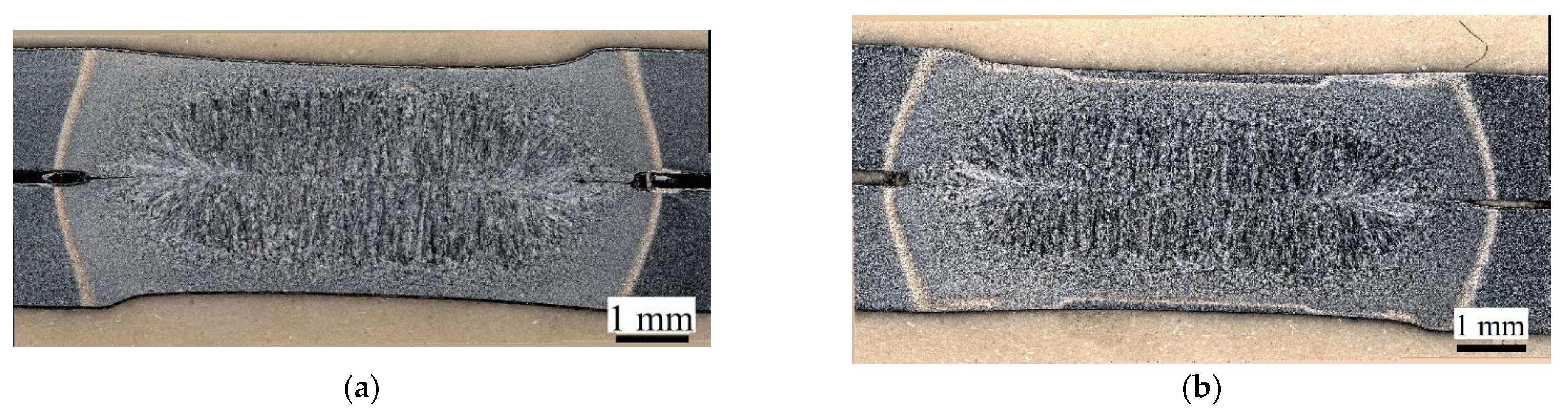
The primary microstructure of the steel used in the hot-stamping process consists of ferrite and pearlite with a tensile strength of about 500 MPa. During hot-stamping, a blank is first heated in an approximate temperature of 910 °C in order to become austenitic. Next, the blank is formed and quenched simultaneously. It is cooled and quenched by cooling ducts existing in the die. This process creates a martensitic microstructure in the part and, as a result, improves its strength up to approximately 1500 MPa [6]. The material used in this study was Usibor1500 steel in both the uncoated and Al-Si coated forms. The thickness of both types of selected steels was 1.8 mm. The chemical compositions of these two sheets of steel are reported in Table 1. The steels underwent the hot-stamping process under similar conditions. They were austenitized for 6 min at 910 °C, and then they were quenched. The oxidation formed on the surface of the uncoated steel was removed through sandblasting.

2.2. Microstructure

Metallographic sections of the coated steels were catered before and after quenching in order to measure the thickness of the coating and to determine the microstructure of the material. Figure 1 illustrates the substructure and formed changes in the thickness of the Al-Si coating before and after the hot-stamping operation. The microstructure of the raw material is a combination of ferrite and pearlite, which was converted into a martensite microstructure after hot-stamping. On the other hand, after hot-stamping, the Al-Si coating diffused to the base metal, transformed into an alloyed intermetallic layer, and the average thickness of the layer increased from 27 μm to 37 μm. This coating layer structure consists of Al-Fe-Si and different intermetallic compounds of α-Fe with Al and Si in a solid solution (e.g., FeAl2 and Fe2SiAl2) [9,22,23].

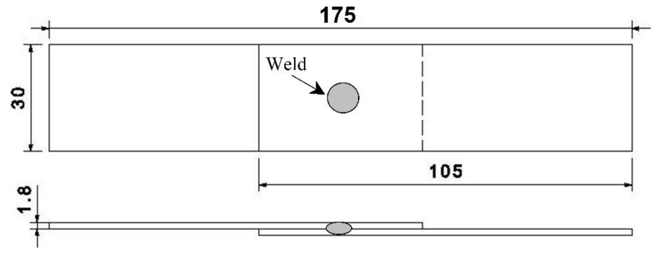
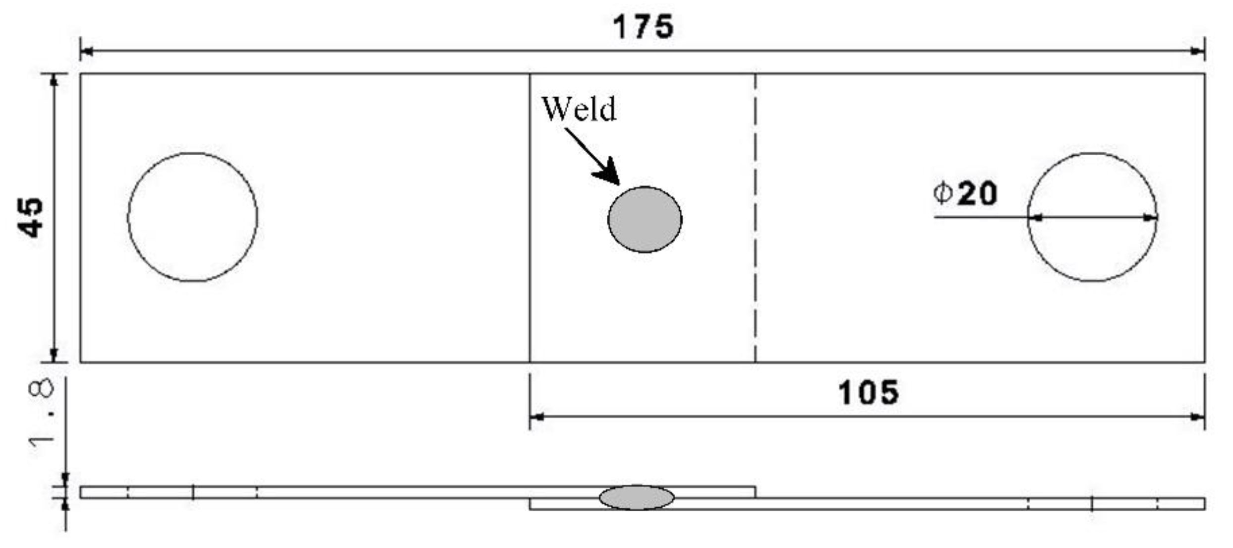
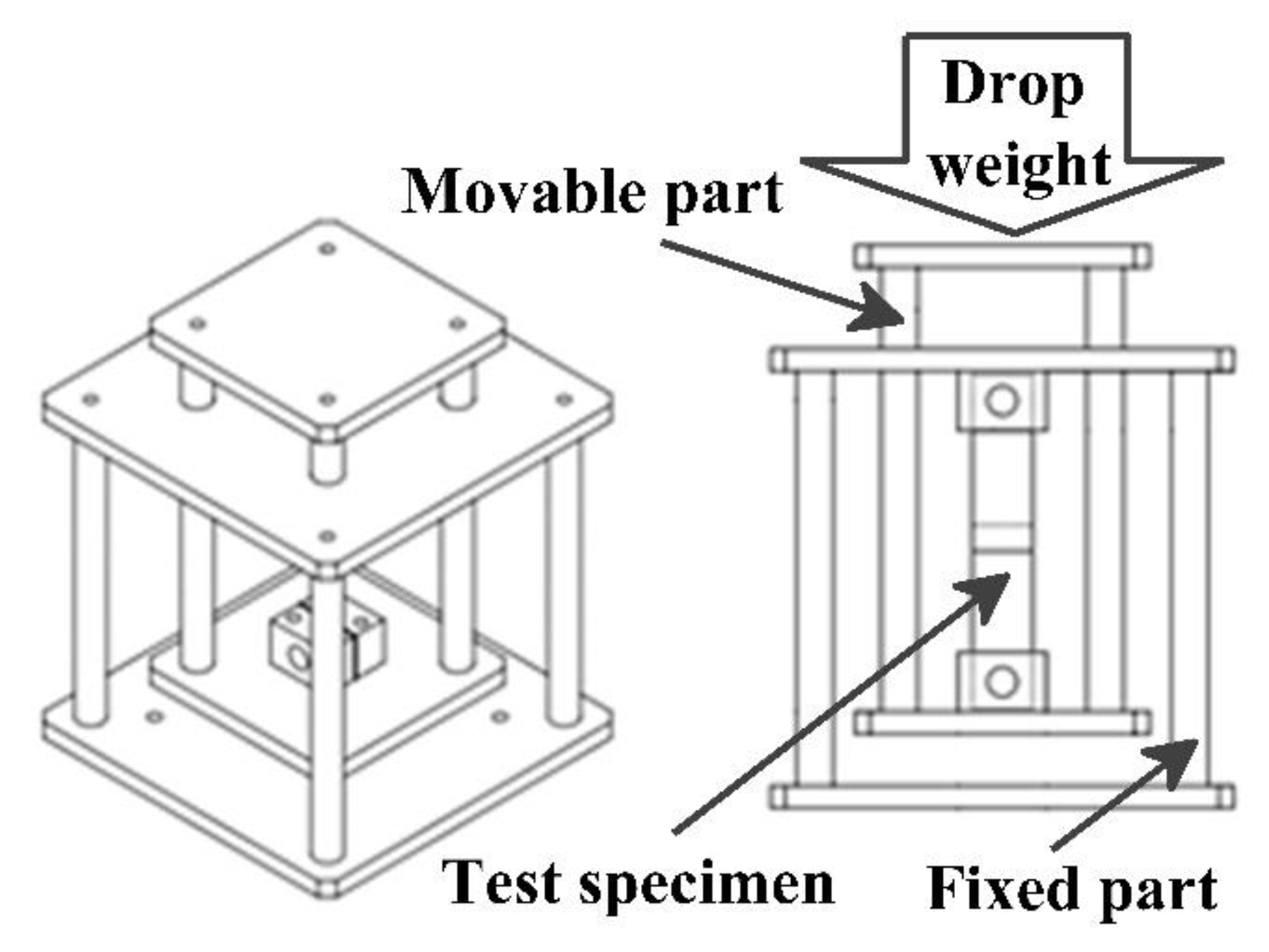
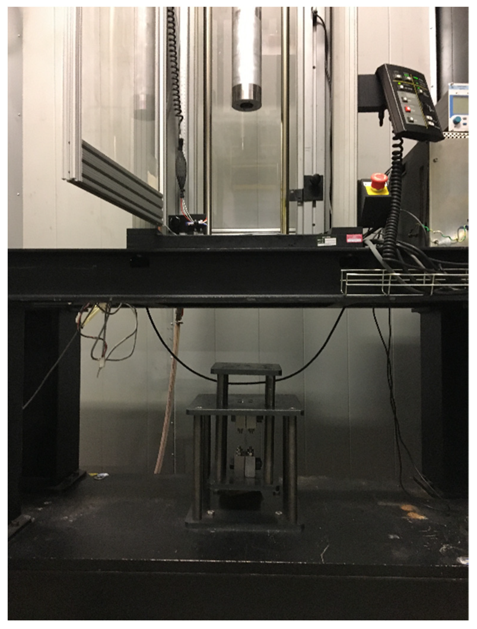
2.3. Mechanical Tests

In order to determine the effects of Al-Si coating on the static strength of welded joints, the tensile shear test was performed. According to ISO 14273, the coated and uncoated steels were cut into 105 mm × 30 mm pieces for preparing static tensile shear specimens [24]. The dimensions and overlap are shown in Figure 2. The initial free span between the clamps was 95 mm.
The cut pieces underwent a thermal process similar to the hot-stamping process. The oxides formed on uncoated pieces were removed using a sandblasting machine. Tensile shear tests were performed on a 100 kN servo-hydraulic test machine at a crosshead speed of 1 mm/min.
The dynamic impact test is a method for determining the dynamic properties of resistance spot-welding. Different kinds of impact tests such as tensile shear and cross tension can be conducted by using the required fixtures. The typical methods of impact tests on spot welding joints are realized using either a pendulum machine or a drop tower. A pendulum machine contains a fixed and movable part and is equipped by a U-shaped hammer developed by Bayraktar et al. according to the idea of Grumbach and Sanz [1].
The most common impact testing system is a drop tower. Chao et al. developed a drop weight machine for spot-welded joints. They added some details to an original drop weight machine to make it appropriate for testing welded joints [25]. In order to investigate the effects of Al-Si coating on the dynamic behavior of welded joints, some impact tensile shear tests on spot-welded joints by using a drop test machine were performed. Based on the ISO14323 standard procedure, the coated and uncoated steels were cut into 105 mm × 45 mm pieces [26]. The dimensions and overlap of the impact tensile shear test specimen are shown in Figure 3. The initial free span between the clamps was 95 mm.
Similar to static test samples, the cut pieces underwent a thermal process similar to hot-stamping and the samples were sandblasted to remove the oxides formed on uncoated pieces. A Tecna 8105 AC (Tecna SA, Bologna, Italy) welding machine was used for performing resistance spot welds. The exact values of the current and force were measured using a Rogowski coil and piezoelectric load cell. According to AWS D8.9, the welding electrode was RWMA group A, Class 2, truncated cone nose, with a face diameter of 8 mm [27]. The welding parameters for preparing test specimens were selected based on some previous practical welding experiences using these types of material. The electrode force was adjusted to 5.7 kN and all welds were performed in 3 pulses. Since the aim was to achieve the maximum possible tensile strength of the welded joints, the selected parameters were at the acceptable range of weldability and mainly close to the expulsion condition. Representative cross-sections for both coated and uncoated sheets are shown in Figure 4 with a welding current of 8.2 kA applied over 9 cycles in 3 pulses.
To carry out the impact test on the specimens using the drop test system, a fixture shown in Figure 5 was designed and fabricated. This fixture consisted of a fixed and a moving part. The test specimens were locked between these parts. After releasing the dropped weight, it stroked the moving part and a force was exerted on the specimens.
A Dynatup 9250 HV (Instron, Norwood, MA, USA) drop tower was used to conduct the test. This machine is designed to raise a drop weight to the desired height and release it to strike the test specimen. The impact energy from the drop tower can be adjusted by changing either the impact velocity by the drop height or mass by the drop weight, as the equation for the kinetic energy prescribes:
Ekin = 0.5 m × v2
The drop tower and the fabricated fixture, positioned over the base of the system, is shown in Figure 6.

3. Results and Discussion

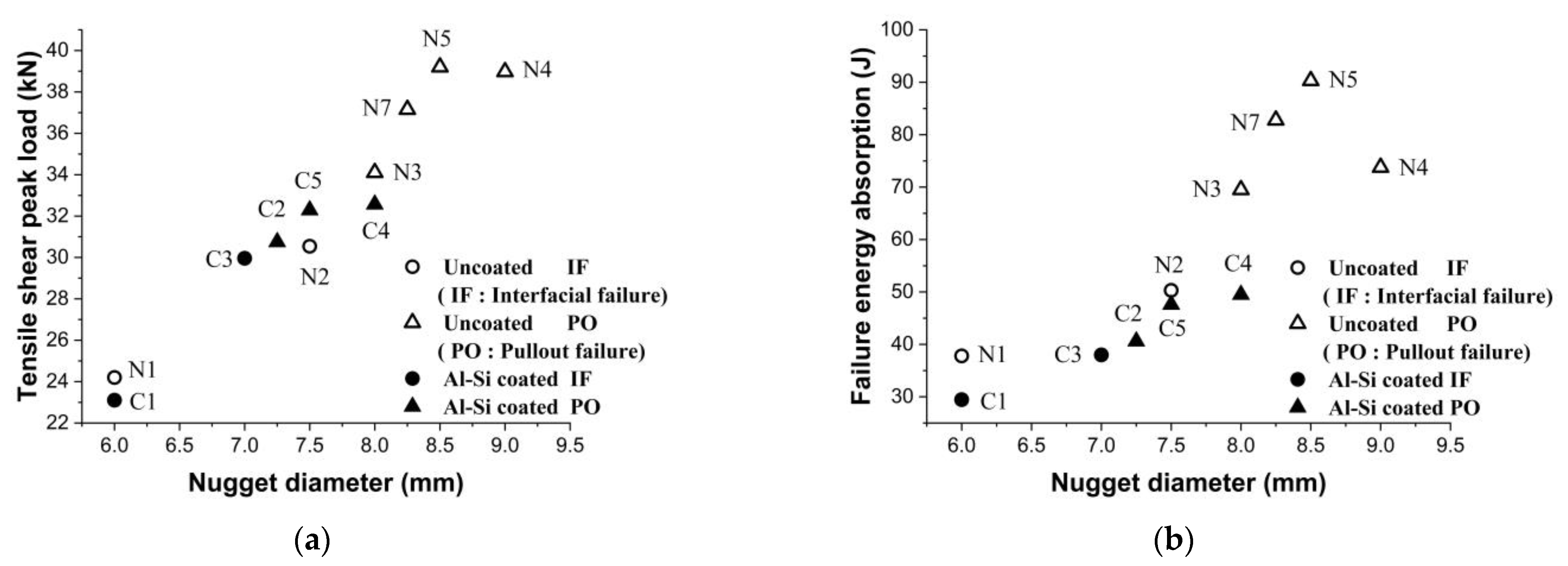
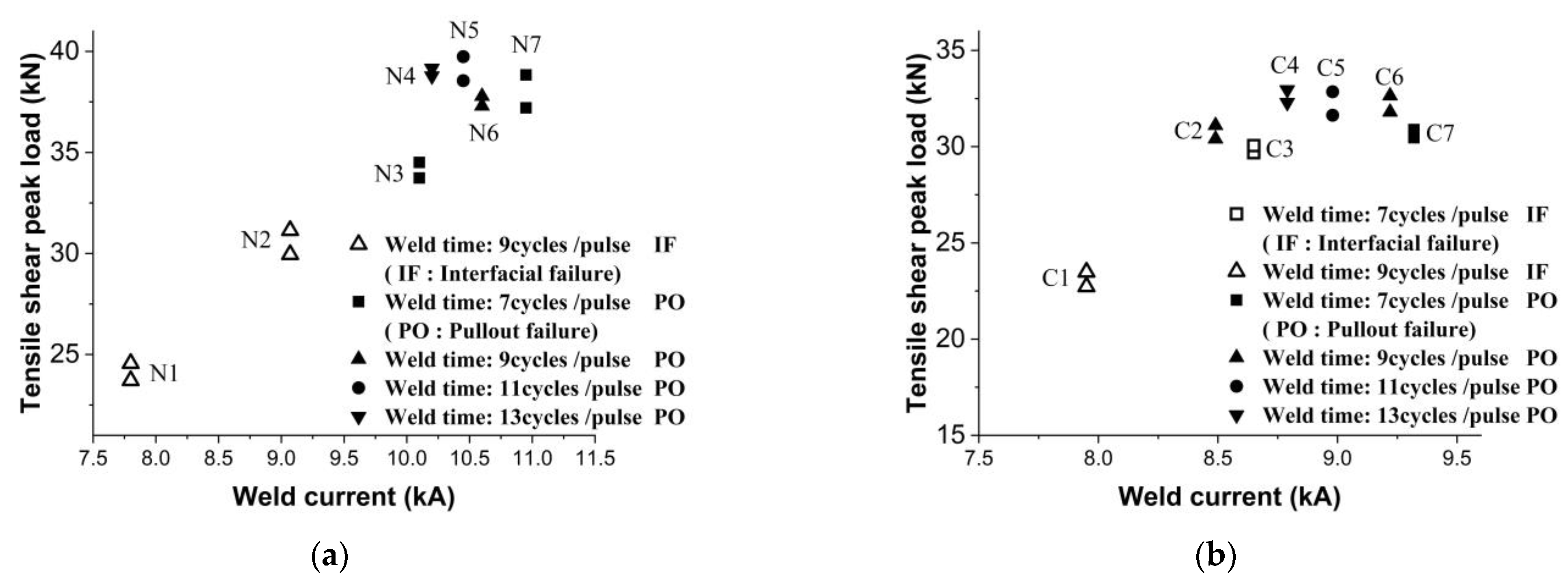
3.1. Tensile Shear Failure Loads

The purpose of this study was to determine the suitable welding parameters required to achieve the highest tensile load capability of the welded joints. Hence, because of selecting most of the welding parameters near the expulsion condition, the number of specimens was limited and redundant tests were avoided. For both types of materials, seven tensile shear strength specimens with at least two repetitions were prepared by applying different combinations of welding current and time. The welding parameters are shown in Table 2. Among these seven selected welding parameters, four combinations were near the expulsion condition for achieving the maximum tensile shear failure load and the other three were relatively far from this condition to allow studying the effects of welding parameters on tensile shear peak load. The effects of welding current and time on the tensile shear failure load of welded joints for both types of steel were determined. The data are represented in Figure 7.
Because of the limited number of tests for each welding time, tensile peak load versus welding current for all of the welding times are shown in one graph. It is worth mentioning that all of the weldings were conducted in three pulses. In general, the uncoated specimens exhibited a higher tensile failure load than the Al-Si coated specimens. The maximum tensile failure load of the welded joint for the uncoated steel was 39.7 kN at 10 kA welding current and 11 cycles/pulse welding time, while it was 33.0 kN for the Al-Si coated steel at 8.8 kA welding current and 13 cycles/pulse welding time. For both types of material, when the selected welding current was in low range the failure mode was the IF type. When the welding current increased, the strength of the joint improved and the failure mode changed to PO. These two failure modes, IF and PO, are shown in Figure 8.

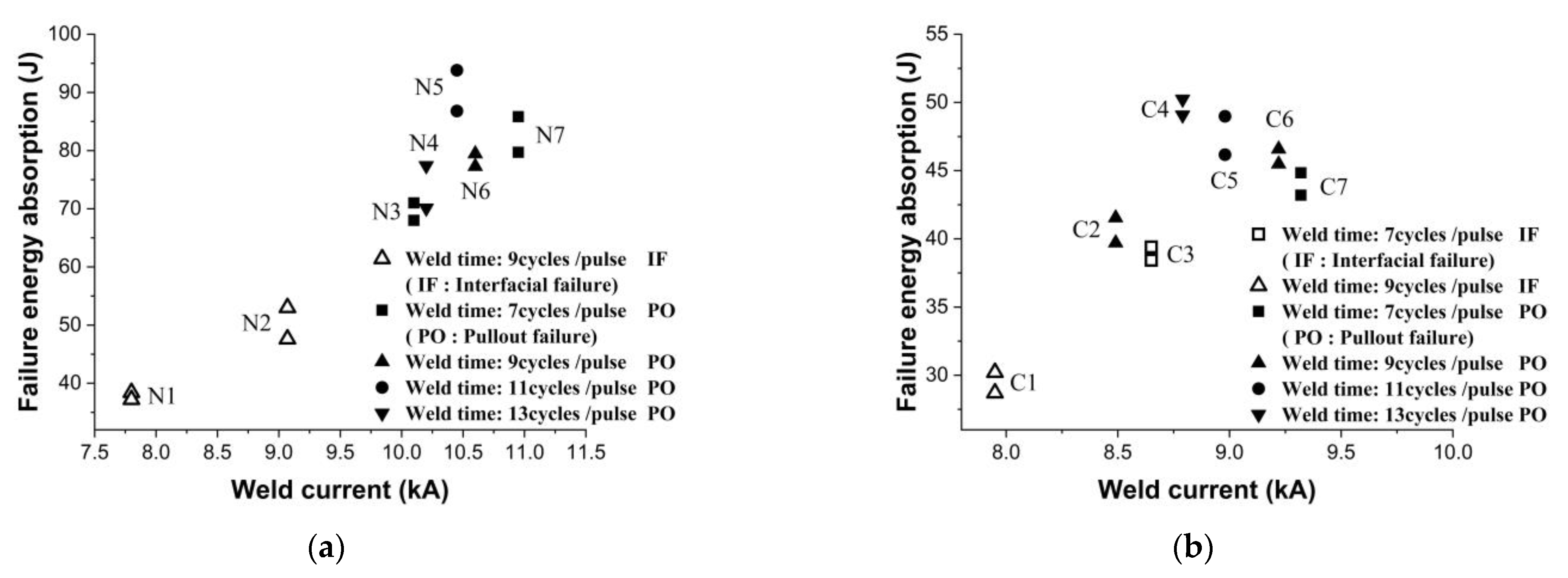
3.2. Failure Energy Absorption

The effects of the welding parameters on the failure energy absorption of the welded joints for both types of materials are reported in Figure 9. Similar to tensile failure load, the energy absorption of welded joints improved by increasing welding current at a welding time of nine cycles/pulse. When the selected welding parameters were near the expulsion condition, the value of energy absorption was acceptable. The maximum failure of energy absorption for the uncoated welded joint was 93.8 J at a 10 kA of welding current and 11 cycles/pulse of welding time, while it was 50.95 J for the Al-Si coated steel at 8.8 kA and 13 cycles/pulse of welding time.

3.3. Correlation of Nugget Diameter on Tensile Failure Load and Failure Energy Absorption

In general, weld nugget diameter is regarded as a criterion for the quality and strength of spot-welded joints. The effect of weld nugget diameter on the tensile failure load and energy absorption of the specimens is shown in Figure 10. It was observed that for the uncoated specimens with increasing nugget diameters of up to 8.5 mm, the tensile failure force and energy absorption increased and then, despite increasing nugget diameter, decreased. For the Al-Si coated specimens, by increasing weld nugget diameter the tensile failure and energy absorption increased.

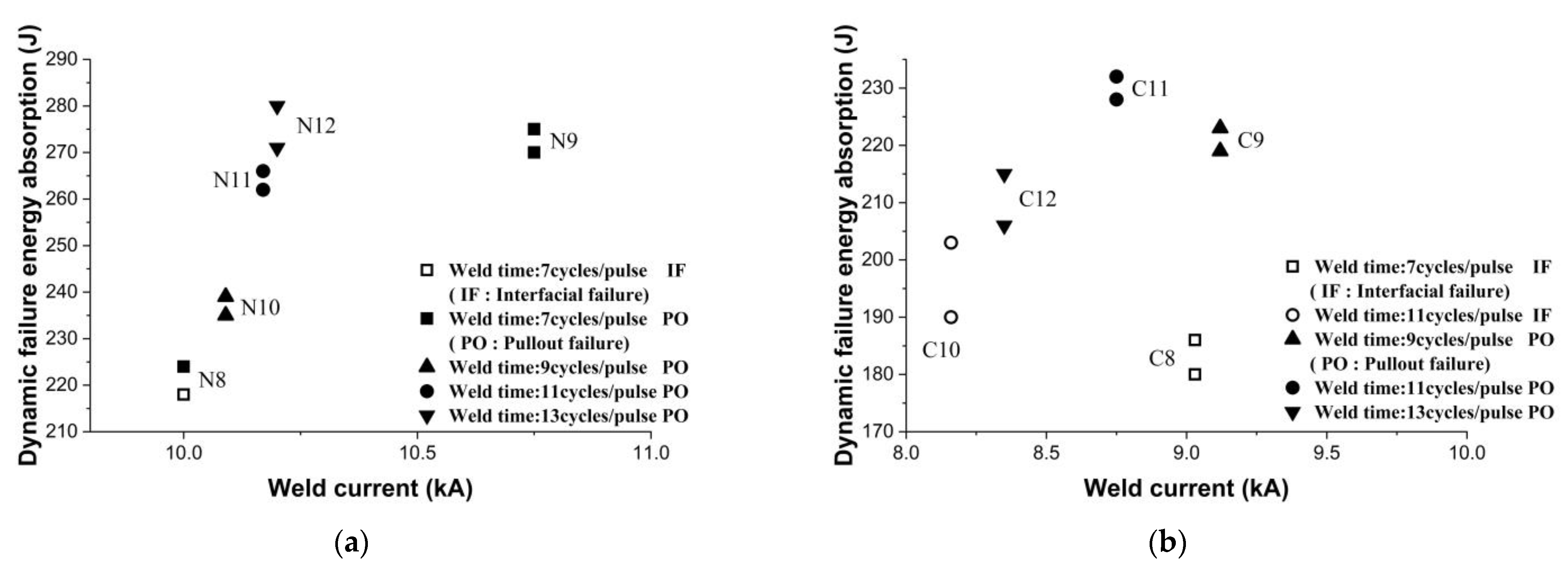
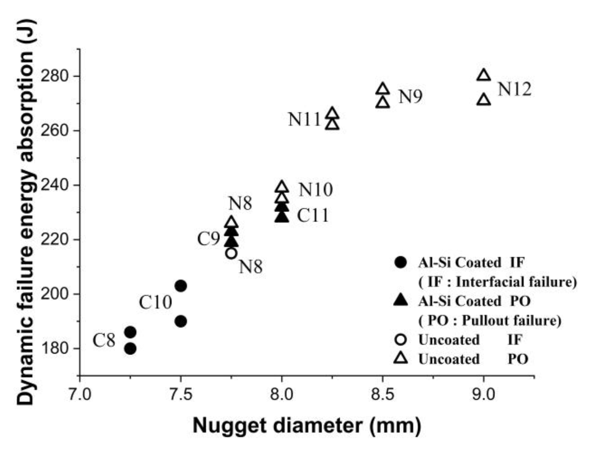
3.4. Impact Test Results

For both types of sheets, five impact test specimens with at least two repetitions were prepared by applying different combinations of welding current and time near the expulsion condition for achieving the highest impact failure load. Impact tests were conducted on these specimens. The welding parameters are shown in Table 3. The effects of the welding parameters on the dynamic failure energy absorption of the welded joints for both types of materials are shown in Figure 11.
The purpose of this study was to determine the suitable welding parameters to achieve the maximum dynamic load capability of the welded joints. Hence, because of selecting the welding parameters near the expulsion condition, the number of specimens was limited and redundant tests were avoided. Because of the limited number of tests for each welding time, dynamic failure energy absorption versus welding current for all of the welding times are shown in one graph. It is worth mentioning that all of the weldings were conducted in three pulses. In general, the uncoated specimens exhibited a higher impact failure energy absorption than the Al-Si coated specimens. The maximum dynamic failure energy absorption for the uncoated welded joint was 280 J at 10.12 kA welding current and 13 cycles/pulse of welding time, while it was 232 J for Al-Si coated steel at 8.84 kA and 11 cycles/pulse of welding time. The effect of weld nugget diameter on dynamic failure energy absorption of the specimens is shown in Figure 12. It is observed that for both types of material, an increasing nugget diameter caused the dynamic failure energy absorption to increase.
The results show that the probability of IF fracture for Al-Si coated specimens is more than uncoated specimens. This phenomenon exhibited that the failure behavior of welded joints for Al-Si coated hot-stamped steel is worse than uncoated steel during impact forces such as crashes. The typical failure modes of specimens such as IF failure or PO failure after impact test are shown in Figure 13.

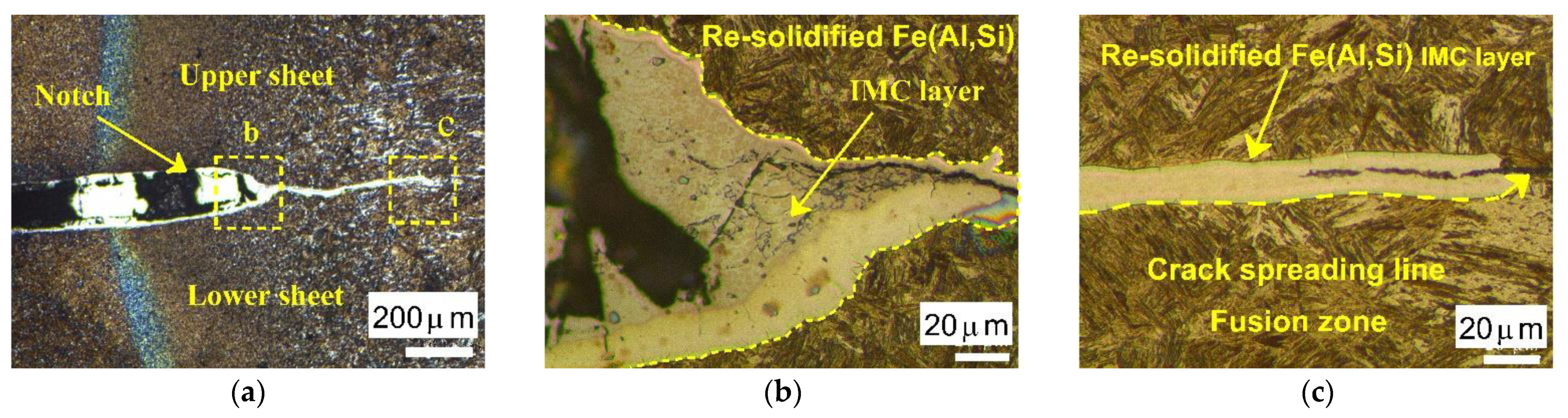
3.5. Effects of Al-Si Coating on Mechanical Behavior of Welded Joint

During the spot welding of hot-stamped Al-Si coated steels, the coating tends to melt due to the high temperature at the faying interface, and a large portion of the molten coating is displaced from under the electrodes and gathers around the weld nugget edges. Some portions of the coating remain on the molten and solidified area and create Al-Fe intermetallic phases. The presence of brittle Al-Fe phases in the weld nuggets causes a decrease in their strength. Figure 14a shows an optical image of the area around the welded zone. Figure 14b,c shows enlarged images of region “b” and “c”, respectively. Because of aggregation of the molten Al-Si coating after weld solidification, the boundary of the weld nugget near the faying surfaces is weakly bonded. In addition, the presence of a notch creates a crack in the edge of the weld nugget, which is due to the concentration of stress in this area. The existence of molten Al-Si around the fusion zone may penetrate cracks through the fragile bonded area and spread along the fusion zone. Hence, in the case of Al-Si coated steel (compared to uncoated steel) the presence of brittle Al-Fe phases in the weld nuggets decreases the mechanical properties of the welded joints and causes a decrease in the maximum tensile failure load and energy absorption in both static and impact tests. Additionally, it increases the risk of changing failure mode from PO to IF fracture in these tests.

4. Conclusions

The effects of Al-Si coating on the static and dynamic tensile shear strength of RSW joints of hot-stamped steels were studied. From this experimental research, the conclusions are as follows:
  • The static tensile shear failure load of RSW joints of coated and uncoated steels increases with an increasing welding current and time;
  • After RSW of hot-stamped Al-Si coated steels, the coating tends to melt and create Al-Fe intermetallic phases at the welding zone which causes a decrease in the welded joint strength;
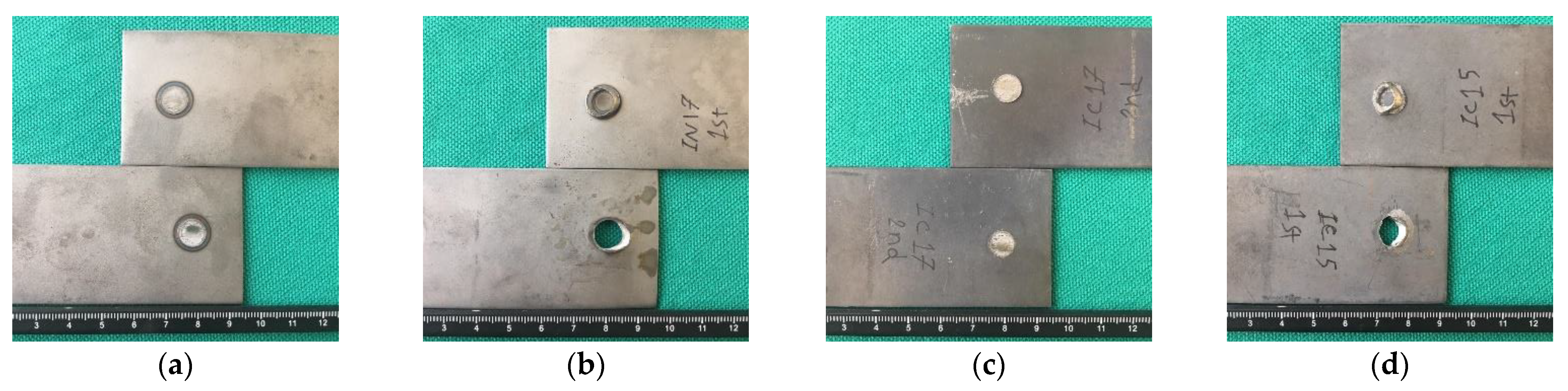
  • Because of the aggregation of molten Al-Si in the edge of the weld nugget, the static tensile failure load and dynamic failure energy absorption of Al-Si coated steel is lower than uncoated steel, and the risk of changing failure mode from Po to IF increases in dynamic tests;
  • The maximum tensile shear failure load of welded joints for uncoated steel is 39.7 kN while it is 33.0 kN for Al-Si coated steel;
  • The maximum dynamic failure energy absorption obtained for welded joints of uncoated steel is 280 J, while it is 232 J for Al-Si coated steel;
  • Due to a lower tensile shear failure capacity, failure energy absorption, and high probability of IF failure for Al-Si coated, the tensile strength behavior of welded joints is worse for Al-Si coated hot-stamped steel than uncoated steel.

Author Contributions

Conceptualization, A.A., M.H. and C.V.N.; data curation, A.A.; formal analysis, A.A.; investigation, A.A., M.H. and C.V.N.; Methodology, A.A., M.H. and C.V.N.; project administration, M.H.; resources, A.A.; supervision, M.H. and C.V.N.; visualization, A.A.; writing—original draft, A.A.; writing—review & editing, A.A., M.H. and C.V.N. All authors have read and agreed to the published version of the manuscript.

Funding

This research received no external funding.

Data Availability Statement

The data presented in this study are available on request from the corresponding author.

Conflicts of Interest

The authors declare no conflict of interest.

References

  1. Bayraktar, E.; Kaplan, D.; Buirette, C.; Grumbach, M. Application of impact tensile testing to welded thin sheets. J. Mater. Process. Technol. 2004, 145, 27–39. [Google Scholar] [CrossRef]
  2. Xing, Z.; Bao, J.; Yang, Y. Numerical simulation of hot stamping of quenchable boron steel. Mater. Sci. Eng. A 2009, 499, 28–31. [Google Scholar] [CrossRef]
  3. Brauser, S.; Pepke, L.-A.; Weber, G.; Rethmeier, M. Deformation behaviour of spot-welded high strength steels for automotive applications. Mater. Sci. Eng. A 2010, 527, 7099–7108. [Google Scholar] [CrossRef]
  4. Zhang, H.; Senkara, J. Resistance Welding: Fundamentals and Applications; CRC Press: Boca Raton, FL, USA, 2011. [Google Scholar]
  5. Karbasian, H.; Tekkaya, A.E. A review on hot stamping. J. Mater. Process. Technol. 2010, 210, 2103–2118. [Google Scholar] [CrossRef]
  6. Ghiotti, A.; Bruschi, S.; Sgarabotto, F.; Bariani, P. Tribological performances of Zn-based coating in direct hot stamping. Tribol. Int. 2014, 78, 142–151. [Google Scholar] [CrossRef]
  7. Cha, J. A Study on Resistance Spot Weldability of Aluminum Coated Sheet Steels. Master’s Thesis, Pukyong National University, Busan, Korea, 2002. [Google Scholar]
  8. Cheon, J.Y.; Vijayan, V.; Murgun, S.; Park, Y.D.; Kim, J.H.; Yu, J.Y.; Ji, C. Optimization of pulsed current in resistance spot welding of Zn-coated hot-stamped boron steels. J. Mech. Sci. Technol. 2019, 33, 1615–1621. [Google Scholar] [CrossRef]
  9. Ji, C.-W.; Jo, I.; Lee, H.; Choi, I.-D.; Kim, Y.D.; Park, Y.-D. Effects of surface coating on weld growth of resistance spot-welded hot-stamped boron steels. J. Mech. Sci. Technol. 2014, 28, 4761–4769. [Google Scholar] [CrossRef]
  10. Ighodaro, O.; Biro, E.; Zhou, Y. Comparative effects of Al-Si and galvannealed coatings on the properties of resistance spot welded hot stamping steel joints. J. Mater. Process. Technol. 2016, 236, 64–72. [Google Scholar] [CrossRef]
  11. Sun, X.; Khaleel, M.A. Dynamic strength evaluations for self-piercing rivets and resistance spot welds joining similar and dissimilar metals. Int. J. Impact Eng. 2007, 34, 1668–1682. [Google Scholar] [CrossRef]
  12. Chao, Y. Failure mode of spot welds: Interfacial versus pullout. Sci. Technol. Weld. Join. 2003, 8, 133–137. [Google Scholar]
  13. Choi, H.-S.; Park, G.-H.; Lim, W.-S.; Kim, B.-M. Evaluation of weldability for resistance spot welded single-lap joint between GA780DP and hot-stamped 22MnB5 steel sheets. J. Mech. Sci. Technol. 2011, 25, 1543. [Google Scholar] [CrossRef]
  14. Zhang, H.; Qiu, X.; Xing, F.; Bai, J.; Chen, J. Failure analysis of dissimilar thickness resistance spot welded joints in dual-phase steels during tensile shear test. Mater. Des. 2014, 55, 366–372. [Google Scholar] [CrossRef]
  15. Zhang, K.; Wu, L.; Tan, C.; Sun, Y.; Chen, B.; Song, X. Influence of Al-Si coating on resistance spot welding of Mg to 22MnB5 boron steel. J. Mater. Process. Technol. 2019, 271, 23–35. [Google Scholar] [CrossRef]
  16. Li, Y.; Cui, X.; Luo, Z.; Ao, S. Microstructure and tensile-shear properties of resistance spot welded 22MnMoB hot-stamping annealed steel. J. Mater. Eng. Perform. 2017, 26, 424–430. [Google Scholar] [CrossRef]
  17. Liang, X.; Yuan, X.; Wang, H.; Li, X.; Li, C.; Pan, X. Microstructure, mechanical properties and failure mechanisms of resistance spot welding joints between ultra high strength steel 22MnB5 and galvanized steel HSLA350. Int. J. Precis. Eng. Manuf. 2016, 17, 1659–1664. [Google Scholar] [CrossRef]
  18. Paveebunvipak, K.; Uthaisangsuk, V. Characterization of static performance and failure of resistance spot welds of high-strength and press-hardened steels. J. Mater. Eng. Perform. 2019, 28, 2017–2028. [Google Scholar] [CrossRef]
  19. Tan, N.; Hong, J.; Lei, M.; Jin, X.; Zheng, H.; Luo, Z. Tensile-shear fracture behaviour of resistance spot-welded hot stamping sheet steel with Al–Si coating. Sci. Technol. Weld. Join. 2020, 25, 525–534. [Google Scholar] [CrossRef]
  20. Chen, R.; Zhang, C.; Lou, M.; Li, Y.; Carlson, B.E. Effect of Al-Si coating on weldability of press-hardened steels. J. Mater. Eng. Perform. 2020, 29, 626–636. [Google Scholar] [CrossRef]
  21. Fuan, H.; Mingtu, M.; Jianping, L.; Guodong, W. State of the art of impact testers for spot welds. Sci. Eng. 2014, 1, 59–66. [Google Scholar]
  22. Ding, Y.; Shen, Z.; Gerlich, A. Refill friction stir spot welding of dissimilar aluminum alloy and AlSi coated steel. J. Manuf. Process. 2017, 30, 353–360. [Google Scholar] [CrossRef]
  23. Cao, X.; Yi, Z.; Xu, C.; Luo, Z.; Duan, J.A. Study on laser/DP-MIG hybrid welding-brazing of aluminum to Al-Si coated boron steel. J. Manuf. Process. 2021, 64, 333–340. [Google Scholar] [CrossRef]
  24. Institurion, B.S. BS EN ISO 14273: 2001 Specimen Dimensions and Procedure for Shear Testing Resistance Spot, Seam and Embossed Projection Welds; ISO: Geneva, Switzerland, 2001. [Google Scholar]
  25. Chao, Y.J.; Wang, K.; Miller, K.; Zhu, X.-K. Dynamic separation of resistance spot welded joints: Part I—Experiments. Exp. Mech. 2010, 50, 889–900. [Google Scholar] [CrossRef]
  26. Welding, R.S. Projection Welds-Destructive Testing of Welds-Specimen Dimensions and Procedure for Impact Shear Test and Cross-Tension Testing; ISO: Geneva, Switzerland, 2006. [Google Scholar]
  27. American Welding Society. Test Methods for Evaluating the Resistance Spot Welding Behavior of Automotive Sheet Steel Materials; American Welding Society: Miami, FL, USA, 2012. [Google Scholar]
Figure 1. Microstructure of material and appearance of Al-Si coating: (a) as-received condition and (b) after heat treatment similar to the hot-stamped condition.
Metals 11 00976 g001
Figure 2. Dimensions of the static tensile shear test sample (dimensions in mm).
Metals 11 00976 g002
Figure 3. Dimensions of the impact tensile shear test sample (dimensions are in mm).
Metals 11 00976 g003
Figure 4. Representative cross-sections of (a) Al-Si coated hot-stamped Usibor 1500 and (b) uncoated hot-stamped Usibor1500.2.4. Experimental Setup.
Metals 11 00976 g004
Figure 5. Fixture Design for Impact Test.
Metals 11 00976 g005
Figure 6. Instron Dynatup 9250 HV drop tower.
Metals 11 00976 g006
Figure 7. Tensile shear failure loads of welded joint for (a) uncoated hot-stamped Usibor1500 and (b) Al-Si coated hot-stamped Usibor1500.
Metals 11 00976 g007
Figure 8. Typical failure modes of the specimens: (a) Interfacial failure (IF) in uncoated material (Sample No. N2); (b) Pullout failure (PO) in uncoated material (Sample No. N7); (c) IF failure in Al-Si coated material (Sample No. C3); and (d) PO failure in Al-Si coated material (Sample No. C6).
Metals 11 00976 g008
Figure 9. Failure energy absorption of welded joints for (a) uncoated hot-stamped Usibor1500 and (b) Al-Si coated hot-stamped Usibor1500.
Metals 11 00976 g009
Figure 10. (a) Tensile shear failure load with nugget diameter for both types of material and (b) Failure energy absorption with nugget diameter for both types of material.
Metals 11 00976 g010
Figure 11. Dynamic failure energy absorption of welded joints during impact test versus welding parameters for (a) uncoated hot-Scheme 1500 and (b) Al-Si coated hot-stamped Usibor1500.
Metals 11 00976 g011
Figure 12. Dynamic failure energy absorption with nugget diameter for both types of material.
Metals 11 00976 g012
Figure 13. Typical failure modes of the specimens after impact test: (a) interfacial failure (IF) in uncoated material (Sample No. N8); (b) pullout failure (PO) in uncoated material (Sample No. N11); (c) IF failure in Al-Si coated material (Sample No. C10); and (d) PO failure in Al-Si coated material (Sample No. C9).
Metals 11 00976 g013
Figure 14. Optical image of weld nugget: (a) cross-section of weld nugget periphery; (b) enlarged image of region “b”; and (c) enlarged image of region “c”.
Metals 11 00976 g014
Table 1. Chemical composition of Usibor1500 steel.
SteelChemical Composition (wt%)
FeCMnSiCrB
Uncoated Usibor1500980.251.140.270.190.003
Al-Si Coated Usibor1500980.231.140.270.180.003
Table 2. Welding parameters for static tensile shear samples.
Sample NumberCoatingForce (kN)Current (kA)PulsesWeld Time (Cycles)Cooling Time (Cycles)
C1Y5.77.95392
C2Y5.78.49392
C3Y5.78.65372
C4Y5.78.793132
C5Y5.78.983112
C6Y5.79.22392
C7Y5.79.32372
N1N5.77.8392
N2N5.79.07392
N3N5.710.1372
N4N5.710.23132
N5N5.710.453112
N6N5.710.6392
N7N5.710.95372
Table 3. Welding parameters for impact tensile shear samples.
Sample NumberCoatingForce (kN)Current (kA)PulsesWeld Time (Cycles)Cooling Time (Cycles)
C8Y5.79.03372
C9Y5.79.12392
C10Y5.78.163112
C11Y5.78.753112
C12Y5.78.353132
N8N5.710372
N9N5.710.75372
N10N5.710.09392
N11N5.710.173112
N12N5.710.23132
Publisher’s Note: MDPI stays neutral with regard to jurisdictional claims in published maps and institutional affiliations.

