1. Introduction
The use of tailor welded blanks (TWBs) has enabled automotive manufacturers to optimize material use in sheet metal assembly by selectively varying material thickness, alloy and/or temper type and surface coatings [
1]. Over the past few decades, steel TWBs have rapidly developed into numerous commercial products, due to the weight and cost reduction over traditional monolithic stampings. However, the continuous drive to further decrease the weight of vehicles, to improve efficiency, and reduce greenhouse gas emissions, has led to integration of more light metal components into the autobody structure. However, there are several difficulties that must be confronted when producing TWBs from aluminum alloy sheets. Aluminum alloys typically have much lower levels of room temperature formability than steel, while the weldability of aluminum is also more challenging when considering high volume fabrication of tailored blanks. As a solid state welding process, friction stir welding (FSW) is considered as a promising joining technique providing one of the best alternatives to fusion welding (such as laser welding) in order to produce a good combination of microstructure, mechanical properties and formability [
2,
3,
4]. Friction stir welding may be used for various geometries including lap welding, T-joints, and butt welding. Additionally, as a solid-state welding process it can be a grain refinement technique for different materials such as aluminum, magnesium, copper, and steels [
5,
6,
7]. FSW has been demonstrated as an enabling technology for production of aluminum TWBs [
1,
8,
9]. However, there are numerous challenges that remain to be overcome, leading to the need for better analysis tools for studying the effect of blank design on formability performance [
7]. The limiting dome height (LDH) test [
10,
11,
12] is often used to assess the formability of tailor-welded blanks experimentally, and these results have been employed to validate models for simulating the effect of blank design on LDH performance.
According to other published literature, the factors influencing the formability of TWBs are the thickness ratio of the base materials [
13,
14], strength ratio of base materials [
15], and other factors such as weld geometry and mismatch of material between weld zone and base materials [
16]. Panda et al. [
12] investigated the formability of three different TWBs in biaxial tension, where LDH tests were used to evaluate post-weld formability. The effect of blank thickness ratio was studied and the results showed that LDH decreases as the thickness ratio increases. Leitão et al. [
16] documented the influence of the type of mismatch in mechanical properties between weld and base materials on formability of aluminum TWBs. However, the same thickness ratio can be obtained by different combination of base materials. Thus, the limiting thickness ratio (LTR) was introduced as a new factor for prediction of forming limits in TWBs [
11].
The most reliable method to investigate the influences of thickness differentials in TWBs on their formability is experimental. However, it is costly to obtain these results over a varying range of thickness differentials that could be explored for design purposes. Therefore, the current study proposes a finite element simulation approach to investigate the formability of tailor welded blanks. Prior work in this area has yielded some useful results. For example, Chien et al. [
17] employed finite element modeling to estimate the onset of failure in transversely loaded AA5754 TWBs, where the predicted results by simulation compared well with the experimental data. The influences of thickness ratio of base sheets on formability of tailor welded blanks were examined based on three-dimensional finite element models. The failure onset sites of tailor welded blanks were predicted and the quantitative relationships between the Erichsen index values and base thickness ratio were established using the finite element software ABAQUS (Dassault Simulia, version 6.10, Paris, France) [
18]. Wang et al. [
19] studied the deformation characteristics of AA6082 tailor-welded blanks of different thickness combinations by a finite element model during the hot stamping process. Good agreements were achieved between the predicted and experimental results, from which studies were extended to predict the forming features of 1.5 mm to 2.0 mm TWBs.
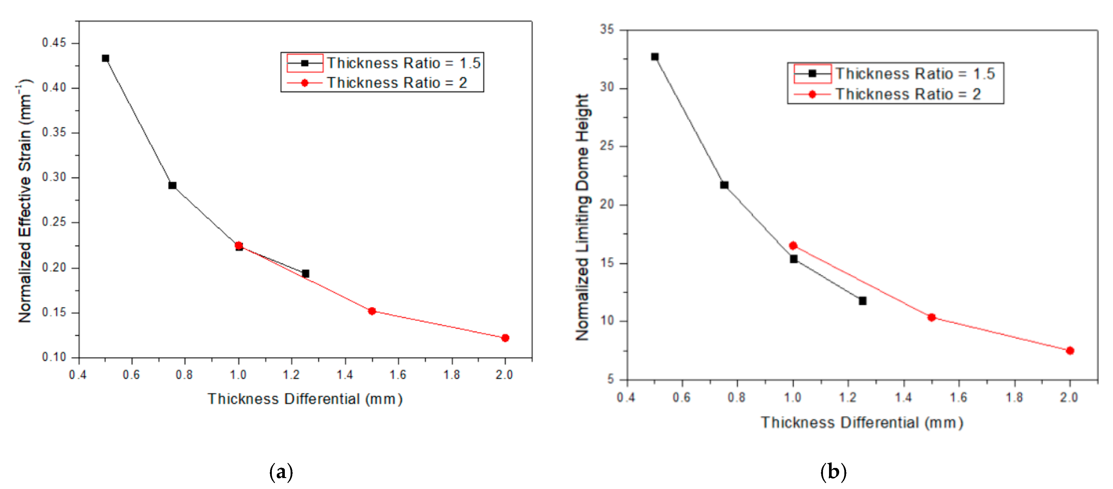
As previous studies have focused on evaluating formability with varying thickness ratios as a means of establish a LTR, this study was designed to investigate how formability of TWBs is affected by changes in thickness differential with a fixed thickness ratio. An understanding of how formability limits may change for a fixed thickness ratio is critical to further enabling rapid industrial implementation of aluminum TWBs. In this paper, results from a finite element model that was developed and validated by experimental results is presented. Building on the prior work, some new insights have been gained regarding the formability of aluminum TWBs for fixed thickness ratios and increasing thickness differentials between dissimilar thickness welded blanks, using the finite element software ForgeNxT (version 2.1, Transvelor, Sophia Antipolis, France) [
20].
2. Experiments and Numerical Modeling
The commercial FEA software package ForgeNxT was utilized to model the limiting dome height deformation process.
Figure 1 shows the FE simulation set-up for the LDH tooling. The model consists of 4 parts: punch, blank, upper clamp, and lower clamp.
A model of the forming process was developed using a finite element approach within the Forge Nxt [
20] software package. An updated Lagrangian scheme with explicit time integration was employed to model the flow of the sheet material, subjected to boundary conditions of restraint around the edges of the blank and velocity boundary conditions imposed by a rigid tool. Material flow was calculated from a three dimensional velocity field. Heat generated by friction and the deformation of the material was also taken into account. An isotropic, viscoplastic Norton–Hoff law was used to model the evolution of material flow stress as a function of strain, strain rate, and temperature. The expression for the deviatoric stress tensor is shown below:
where
is the strain rate tensor,
is the effective strain rate,
K is the material consistency, and m is the strain rate sensitivity. The material consistency
K is a function of temperature T and equivalent strain
, where n is the strain hardening exponent and β is a thermal softening parameter:
This viscoplastic law is capable of modeling material flow stresses in the region of the weld, while also providing the contact stresses with the tool that were used to calculate the friction shear stress at the tool/sheet interface.
Friction at the sliding interface between the sheet and the tool were modeled using a Coulomb law.
where
μ is the friction coefficient,
σo is the current yield stress of the sheet material, and
σn is the normal stress at the contact surface.
Calculation of the flow of material was based on a finite element discretization using an enhanced 3-noded triangular element, where equilibrium equations were solved at each increment using the Newton–Raphson method. The unilateral contact condition was applied to the sheet surfaces by means of a nodal penalty formulation, where both the tool and clamping dies were considered rigid.
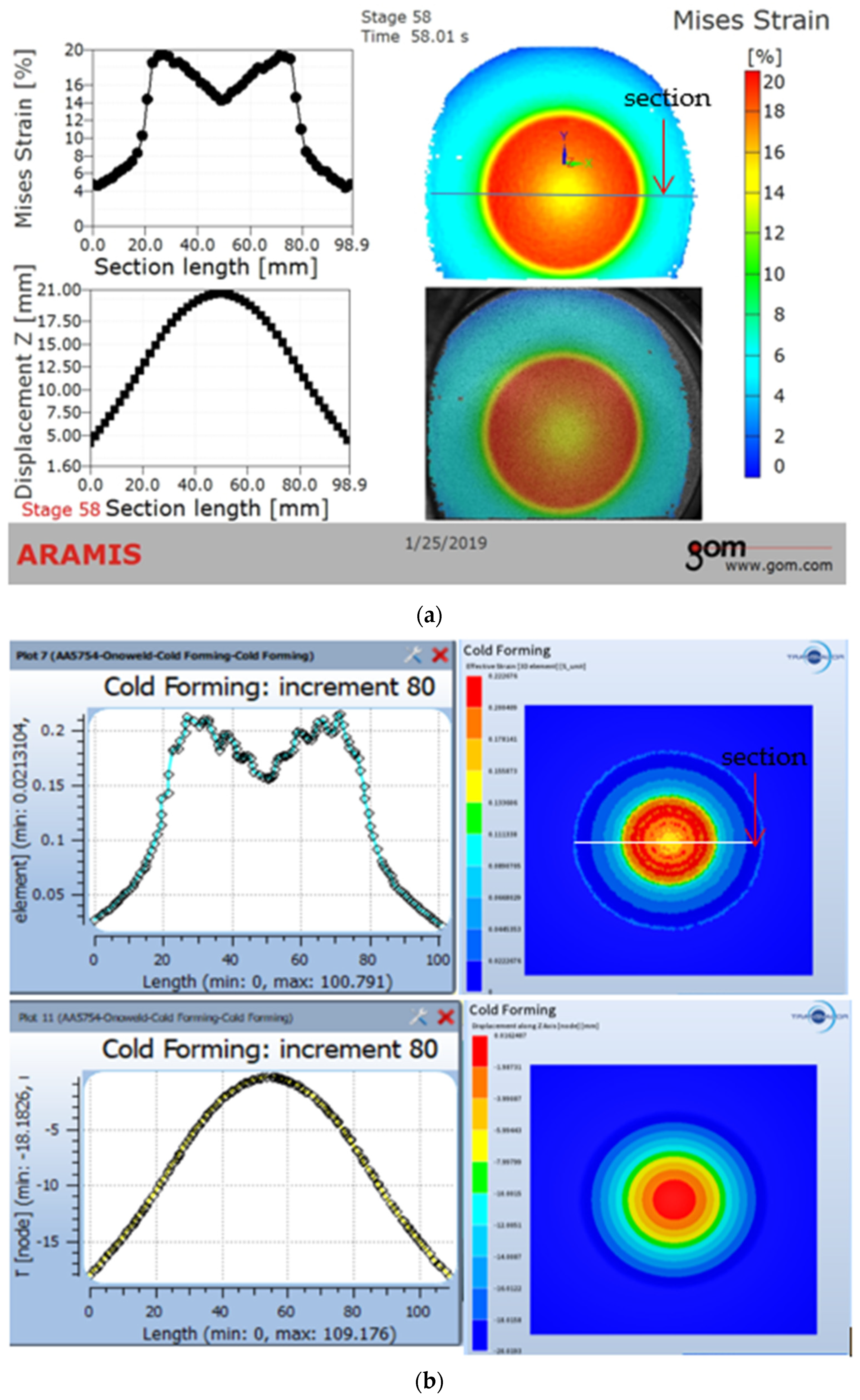
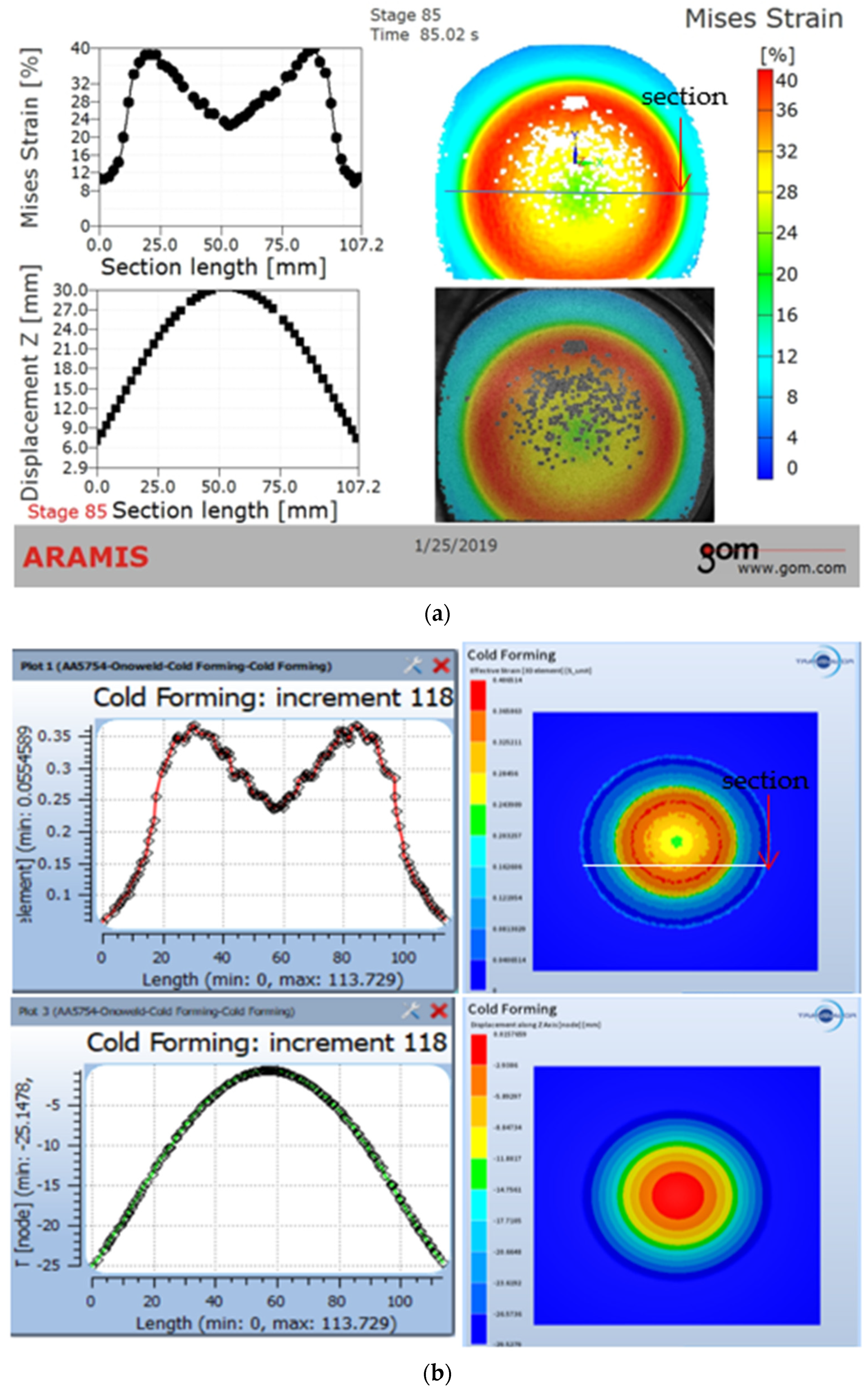
For the finite element modeling, the most important aspect is to validate the numerical model proposed here for prediction of the LDH value by comparing the computed results with experimental data. This requires a comparison of the numerical results in terms of equivalent plastic strain and displacement distribution with the results obtained in the experimental. The aluminum alloy AA 5754-O was used in both experimental and simulation validation. AA 5754 has been an alloy of choice for the automotive structural application owing to its excellent ductility and formability characteristics. The chemical composition and relevant mechanical properties of AA5754 are shown in
Table 1 and
Table 2. For numerical validation, the LDH deformation process is simulated in base material AA5754, with blank thickness of 3 mm, without a weld seam.
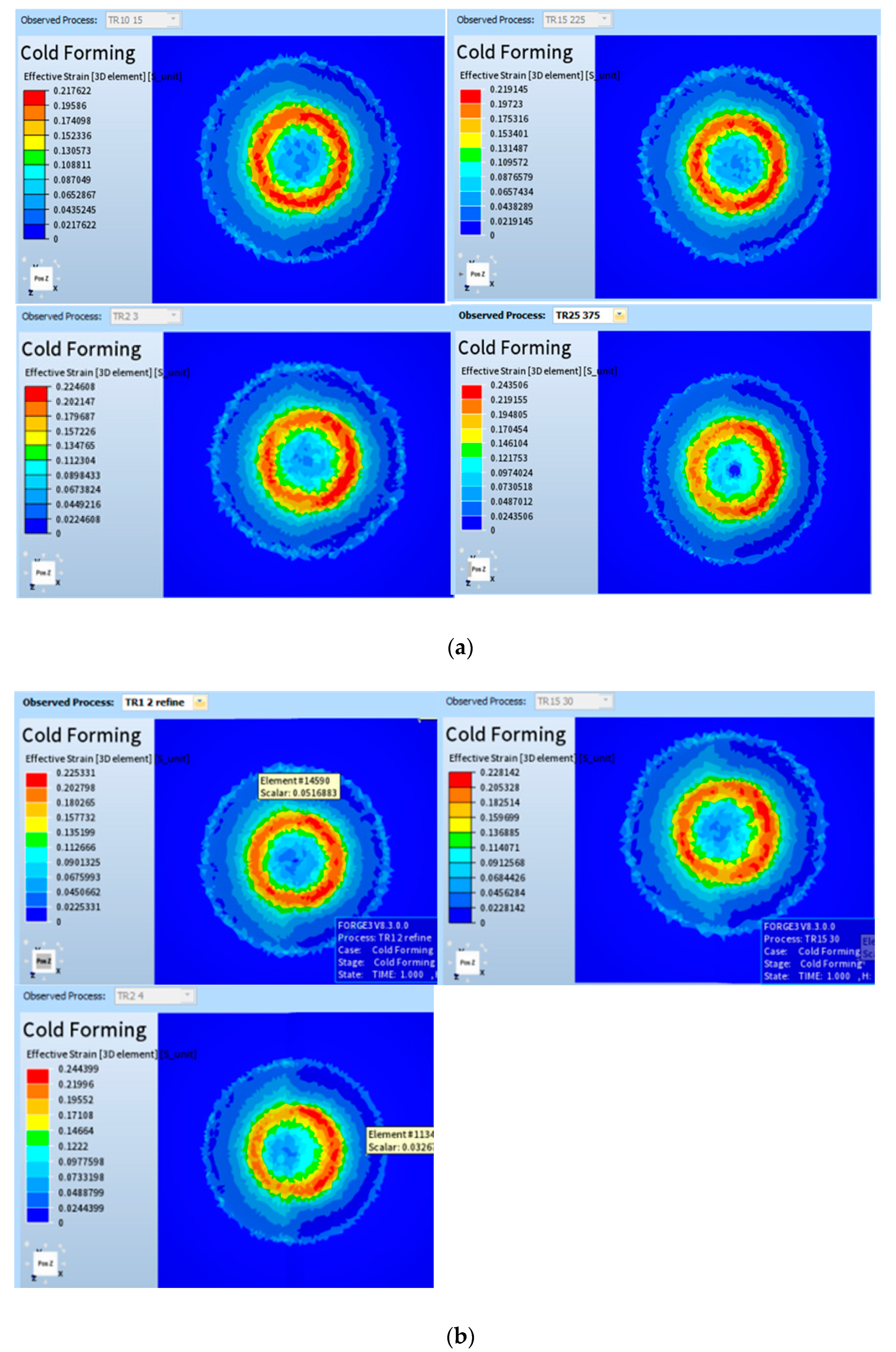
The goal of the study is to investigate the effects of thickness differential on the limiting dome height value in aluminum tailor welded blanks. Thickness ratios of 1.5:1 and 2:1, with varying thickness differentials are considered in our simulation work. For the thickness ratio 1.5:1, four thickness differentials are investigated: 0.5 mm (1.5 mm: 1 mm), 0.75 mm (2.25 mm: 1.5 mm), 1 mm (3 mm: 2mm), and 1.25 mm (3.75 mm: 2.5 mm), respectively. For thickness ratio 2:1, three thickness differentials are investigated: 1 mm (1 mm:2 mm), 1.5 mm (1.5 mm:3 mm), and 2 mm (2 mm:4 mm), respectively.
In the present work, limiting dome height tests were carried out to validate the numerical prediction of LDH values of the blanks and also to check the equivalent plastic strain distribution obtained in the simulations. An Interlaken Servo Press 75 system (Interlaken Technology Corporation, Chaska, MN, USA), shown in
Figure 2a was used for conducting the LDH tests. The sample is rigidly clamped with a grooved clamp-down ring and stretched to fracture with a 100 mm diameter hemispherical dome. The maximum load at fracture is measured and the height of the dome at peak load can be used to define the limit of formability, since plastic instability occurs beyond this point. The ARAMIS Digital Image Correlation (DIC) system (GOM, Braunschweig, Germany) shown in
Figure 2b, is used for measuring and visualizing both displacement distribution and equivalent plastic strain.
Author Contributions
Conceptualization, J.W.; methodology, J.W.; software, M.M.; validation, J.W. formal analysis, J.W.; investigation, J.W.; resources, Y.H.; data curation, J.W.; writing—original draft preparation, J.W.; writing—review and editing, Y.H. and M.M; supervision, Y.H. and M.M; project administration, J.W.; funding acquisition, J.W. All authors have read and agreed to the published version of the manuscript.
Funding
This research was funded by Hunan Provincial Education Department, grant number 19A122 and Hunan Institute of Technology, JY201935 and 2019HY025.
Institutional Review Board Statement
Not applicable.
Informed Consent Statement
Not applicable.
Data Availability Statement
Data supporting the reported results can be obtained from the author upon request.
Acknowledgments
In this section, we acknowledge the support given by Brigham Yong University and Hunan Institute of Technology.
Conflicts of Interest
The authors declare no conflict of interest. The funders had no role in the design of the study; in the collection, analyses, or interpretation of data; in the writing of the manuscript, or in the decision to publish the results.
References
- Hovanski, Y.; Upadhyay, P.; Carsley, J.; Luzanski, T.; Carlson, B.; Eisenmenger, M.; Soulami, A.; Marshall, D.; Landino, B.; Hartfield-Wunsch, S. High-Speed Friction-Stir Welding to Enable Aluminum Tailor-Welded Blanks. JOM 2015, 67, 1045–1053. [Google Scholar] [CrossRef]
- Patel, V.; Li, W.; Wang, G.; Wang, F.; Vairis, A.; Niu, P. Friction Stir Welding of Dissimilar Aluminum Alloy Combinations: State-of-the-Art. Metals 2019, 9, 270. [Google Scholar] [CrossRef]
- Zhou, Y.; Chen, S.; Wang, J.; Wang, P.; Xia, J. Influences of Pin Shape on a High Rotation Speed Friction Stir Welding Joint of a 6061-T6 Aluminum Alloy Sheet. Metals 2018, 8, 987. [Google Scholar] [CrossRef]
- Barbini, A.; Carstensen, J.; Dos Santos, J.F. Influence of Alloys Position, Rolling and Welding Directions on Properties of AA2024/AA7050 Dissimilar Butt Weld Obtained by Friction Stir Welding. Metals 2018, 8, 202. [Google Scholar] [CrossRef]
- Wen, Q.; Li, W.Y.; Wang, W.B.; Wang, F.F.; Gao, Y.J.; Patel, V. Experimental and numerical investigations of bonding interface behavior in stationary shoulder friction stir lap welding. J. Mater. Sci. Technol. 2019, 35, 192–200. [Google Scholar] [CrossRef]
- Su, Y.; Li, W.; Patel, V.; Vairis, A.; Wang, F. Formability of an AA5083 aluminum alloy T-joint using SSFSW on both corners. Mater. Manuf. Process. 2019, 34, 1737–1744. [Google Scholar] [CrossRef]
- Patel, V.; Li, W.; Vairis, A.; Badheka, V. Recent Development in Friction Stir Processing as a Solid-State Grain Refinement Technique: Microstructural Evolution and Property Enhancement. Crit. Rev. Solid State Mater. Sci. 2019, 44, 378–426. [Google Scholar] [CrossRef]
- Hovanski, Y.; Carsley, J.; Carlson, B.; Hartfield-Wunsch, S.; Pilli, S. Comparing laser welding technologies with friction stir welding for production of aluminum tailor-welded blanks. SAE Int. J. Mater. Manuf. 2014, 7, 537–544. [Google Scholar] [CrossRef]
- Merklein, M.; Johannes, M.; Lechner, M.; Kuppert, A. A review on tailored blanks—Production, applications and evaluation. J. Mater. Process. Technol. 2014, 214, 151–164. [Google Scholar] [CrossRef]
- Babu, N.B.K.; Davidson, M.J.; Rao, A.N.; Balasubramanian, K.; Govindaraju, M. Effect of differential heat treatment on the formability of aluminium tailor welded blanks. Mater. Des. 2014, 55, 35–42. [Google Scholar] [CrossRef]
- Gautam, V.; Kumar, A. Experimental and Numerical Studies on Formability of Tailor Welded Blanks of High Strength Steel. Procedia Manuf. 2019, 29, 472–480. [Google Scholar] [CrossRef]
- Panda, S.K.; Ravi Kumar, D. Experimental and numerical studies on the forming behavior of tailor welded steel sheets in biaxial stretch forming. Mater. Des. 2010, 31, 1365–1383. [Google Scholar] [CrossRef]
- Safdarian Korouyeh, R.; Moslemi Naeini, H.; Torkamany, M.J.; Liaghat, G. Experimental and theoretical investigation of thickness ratio effect on the formability of tailor welded blank. Opt. Laser. Technol. 2013, 51, 24–31. [Google Scholar] [CrossRef]
- Bhaskar, V.V.; Narayanan, R.G.; Narasimhan, K. Effect of thickness ratio on formability of Tailor Welded Blanks (TWB). AIP Conf. Proc. 2004, 712, 863–868. [Google Scholar]
- Safdarian, R. The effects of strength ratio on the forming limit diagram of tailor-welded blanks. Ironmak. Steelmak. 2018, 45, 17–24. [Google Scholar] [CrossRef]
- Leitao, C.; Zhang, B.K.; Padmanabhan, R.; Rodrigues, D.M. Influence of weld geometry and mismatch on formability of aluminium tailor welded blanks: Numerical and experimental analysis. Sci. Technol. Weld. Join. 2011, 16, 662–668. [Google Scholar] [CrossRef]
- Chien, W.Y.; Pan, J.; Tang, S.C. A combined necking and shear localization analysis for aluminum sheets under biaxial stretching conditions. Int. J. Plast. 2004, 20, 1953–1981. [Google Scholar] [CrossRef]
- Song, Y.; Hua, L. Influences of thickness ratio of base sheets on formability of Tailor Welded Blanks. Procedia Eng. 2014, 81, 730–735. [Google Scholar] [CrossRef][Green Version]
- Wang, A.; Liu, J.; Gao, H.; Wang, L.L.; Masen, M. Hot stamping of AA6082 tailor welded blanks: Experiments and knowledge-based cloud—finite element (KBC-FE) simulation. J. Mater. Process. Technol. 2017, 250, 228–238. [Google Scholar] [CrossRef]
- Forge NxT, version 2.1; Transvalor: Sophia Antipolis, France, 2018.
| Publisher’s Note: MDPI stays neutral with regard to jurisdictional claims in published maps and institutional affiliations. |
© 2021 by the authors. Licensee MDPI, Basel, Switzerland. This article is an open access article distributed under the terms and conditions of the Creative Commons Attribution (CC BY) license (https://creativecommons.org/licenses/by/4.0/).


