Article

Vibration Characteristics of Hot Rolling Mill Rolls Based on Elastoplastic Hysteretic Deformation

1
National Engineering Research Center for Equipment and Technology of Cold Rolled Strip, Yanshan University, Qinhuangdao 066004, China
2
School of Education, Nanchang Institute of Science & Technology, Nanchang 330108, China
3
College of Electrical Engineering, Yanshan University, Qinhuangdao 006004, China
*
Author to whom correspondence should be addressed.
Metals 2021, 11(6), 869; https://doi.org/10.3390/met11060869
Submission received: 6 April 2021 / Revised: 14 May 2021 / Accepted: 21 May 2021 / Published: 26 May 2021

Abstract

:
Based on the analysis of the influence of roll vibration on the elastoplastic deformation state of a workpiece in a rolling process, a dynamic rolling force model with the hysteresis effect is established. Taking the rolling parameters of a 1780 mm hot rolling mill as an example, we analyzed the hysteresis between the dynamic rolling force and the roll vibration displacement by varying the rolling speed, roll radius, entry thickness, front tension, back tension, and strip width. Under the effect of the dynamic rolling force and considering the nonlinear effect between the backup and work rolls as well as the structural constraints on the rolling mill, a hysteretic nonlinear vertical vibration model of a four-high hot rolling mill was established. The amplitude-frequency equations corresponding to 1/2 subharmonic resonance and 1:1 internal resonance of the rolling mill rolls were obtained using a multi-scale approximation method. The amplitude-frequency characteristics of the rolling mill vibration system with different parameters were studied through a numerical simulation. The parametric stiffness and nonlinear stiffness corresponding to the dynamic rolling force were found to have a significant influence on the amplitude of the subharmonic resonance system, the bending degree of the vibration curve, and the size of the resonance region. Moreover, with the change in the parametric stiffness, the internal resonance exhibited an evident jump phenomenon. Finally, the chaotic characteristics of the rolling mill vibration system were studied, and the dynamic behavior of the vibration system was analyzed and verified using a bifurcation diagram, maximum Lyapunov exponent, phase trajectory, and Poincare section. Our research provides a theoretical reference for eliminating and suppressing the chatter in rolling mills subjected to an elastoplastic hysteresis deformation.

1. Introduction

A hot rolling mill is an important piece of equipment in the iron and steel industry. It is widely used because of its low energy consumption and high efficiency in the rolling process. Hot rolling mills in the modern steel rolling industry exhibit a complex vibration phenomenon because of the increasing requirements on the rolling speed, rolling material strength, product quality, and precision, leading to a series of production and quality problems [1,2,3]. Many studies have been conducted on the chatter theory of rolling mills to reveal their vibration law, so as to eliminate or control the vibration and ensure that the mills run without defects [4,5,6]. Valigi et al. found that an S6-high rolling mill suffers from chatter when rolling high strength steels, which leads to the lower surface finish of rolled strips and variation in the strip thickness. They carried out a detailed experimental study on this problem and proposed measures to suppress vibration [7,8]. Kozhevnikov et al. showed that the rolling process stability can be improved and chatter can be prevented by increasing reduction in adjacent stands and changing the ratio of rolling speeds in these stands [9]. In addition, scientific employees of some companies have presented some representative reports. ThyssenKrupp AG has designed a type of rolling mill called a takode, which can meet rolling requirements of materials with higher strength, larger width, and smaller thickness. At the same time, a variety of technical measures can improve the surface characteristics of work rolls and the rolling accuracy of strips [10,11].
In a rolling process, the vertical vibration of rolling mill rolls will lead to the deformation of the workpiece in the deformation zone, and the equivalent simplification of the deformation process directly affects the accuracy of the vibration model. In early studies, the workpiece was considered equivalent to an elastic element with a linear stiffness, and a vertical vibration model of the rolling mill was established on the basis of the linear theory to study the vibration of the rolling mill [12,13]. However, considering only the linear factors cannot explain the complex vibration phenomenon observed in the actual operation of a rolling mill. Therefore, scholars explored nonlinear factors and phenomena observed during the elastoplastic deformation of workpieces. Swiatoniowski et al. reported that the stiffness of a workpiece varies periodically when the mill is subjected to an external disturbance, leading to parametric vibration and chatter [14]. Some scholars considered the deformation process as a Duffing oscillation to study the rolling mill vibration. Zhang et al. used the plastic finite element method to calculate the plastic deformation characteristics of a strip steel; considering the thermal expansion and wear of rolls, a 3D model of the hot strip rolling process was established [15]. Hot rolling is an elastoplastic deformation process, and a strip steel produces an evident hysteresis phenomenon under the action of a dynamic load [16]. Therefore, the elastoplastic deformation of the workpiece in a rolling process is nonlinear with hysteresis characteristics.
During the vertical vibration of a rolling mill, the interaction between the rolling mill rolls and the workpiece produces a change in the vibration and process parameters in the deformation zone of the workpiece, thus affecting the rolling force. The rolling force is an important component in the vibration model, and the modeling process directly affects the analysis of the vibration results. Therefore, researchers have focused on methods that can help determine the rolling force more accurately [17,18,19,20]. According to different pressure distributions in the forward and backward skid areas, Wu et al. established a rolling force fluctuation model and revealed the relationship between rolling force fluctuations and mill vibration marks [21]. Feng et al. analyzed the influence of the strain rate of a thin slab in the rolling zone on the rolling force during high-speed hot rolling and established a rolling force model of a hot rolled strip based on the Karman equation, which can better predict the stress condition of rolls [22]. Li et al. established a mathematical model of the friction coefficient based on the linear regression of multiple input variables to calculate the rolling force in a hot rolling process, and the effectiveness of the model was proven by conducting an industrial test [23]. Kazeminezhad et al. derived two differential equations considering the change in the contact area width between the roll and the workpiece during the rolling process, and the corresponding expressions for the rolling force were obtained by solving the equations using the Eulerian numerical method. The effects of the friction coefficient, reduction rate, and yield stress on the distribution of the rolling pressure were studied [24]. Peng et al. established a dynamic rolling force model affected by the nonlinear friction between the roll gaps and studied the coupling chatter characteristics of hot rolling mill rolls [25]. Some scholars introduced a deformation penetration coefficient to describe the deformation characteristics of a workpiece in the thickness direction and establish a rolling force model based on the parameter [26]. In the rolling process, the elastoplastic hysteresis deformation characteristics of the workpiece will make the rolling force to exhibit a hysteretic nonlinear characteristic. However, studies on this topic are lacking. Therefore, it is necessary to analyze the rolling force and its influence on the vibration characteristics of rolling mill rolls.
In this study, a dynamic rolling force expression with the hysteresis effect was derived by considering the nonlinear effect of the elastoplastic hysteresis deformation of a workpiece in a hot rolling process. We first analyzed the hysteresis characteristic between the dynamic rolling force and the vibration displacement with the change in the rolling parameters. Second, considering the parametric stiffness between the rolls and the structural constraints on the mill, a nonlinear vibration model of a four-high hot rolling mill was established, and the effects of different parameters on the amplitude-frequency characteristics of the rolling mill rolls were analyzed. Third, the chaotic vibration characteristics of the rolling mill rolls were studied using multiple nonlinear methods to further verify the effectiveness of the vibration model established in this study. Our research has theoretical significance and can play a guiding role in restraining mill chatter and improving the quality and precision of rolling products.
The remainder of the paper is organized as follows. Section 2 presents the rolling force model with hysteresis. By dividing the rolling zone into elastic and plastic zones, the hysteresis characteristics between roll vibration displacement and rolling force are obtained, and the effects of different rolling parameters on the dynamic rolling force are analyzed. Section 3 establishes the nonlinear vibration model of a hot rolling mill under the abovementioned characteristics and obtains the corresponding dynamic equation using the Lagrange principle. Section 4 obtains the subharmonic and internal resonance equations of a rolling mill vibration system using the nonlinear method and discusses the effects of different process parameters on the amplitude and frequency characteristics. Section 5 intuitively shows the chaotic movement trend and process parameter area of a rolling mill vibration system using the numerical simulation method. Finally, Section 6 concludes the paper.

2. Modeling of Dynamic Rolling Force with Hysteresis

A hot rolling mill roll is mainly composed of a mill stand, work rolls, backup rolls, and a workpiece. The work and backup rolls are simplified as a centralized mass block; Figure 1 shows the structure of a hot rolling mill.
The rolling force is an important factor affecting the vertical vibration of a rolling mill. Figure 2 shows the diagram of the deformation process of a workpiece in rolling production. During hot rolling, there is not only plastic deformation, but also elastic deformation at the exit of the workpiece, which cannot be easily ignored. Therefore, in the rolling process, the rolling force acting on the workpiece produces two zones: a plastic deformation zone (I) and an elastic deformation zone (II). In the process of hot rolling, because the strengths of the upper and lower work rolls are much greater than that of the workpiece, it is assumed that there is no material wave before and after rolling.
In Figure 2, R is the radius of the work roll, vR is the rotation speed of the roll, α is the bite angle, φm is the included angle at a distance of m from the center line of the work roll, and vy is the vertical reduction speed of the workpiece at a distance of m from the center line of the work roll. τf and τb are the front and back tensions, respectively. x1 and x3 are the vertical vibration displacements of the upper and lower work rolls, respectively, and x = x1x3, where x is the relative vibration displacement of the upper and lower work rolls. H0 and h0 are the entry and exit thicknesses of the workpiece in the steady-state rolling, respectively. h is the exit thickness when the roller vibrates and is written as: h = h0 + x. lc is the horizontal projection length of the contact arc in the plastic deformation zone, l c = R Δ h , and Δh is the reduced amount of the workpiece, which is written as: Δh = H0h0x.
When the roller vibrates, the vertical reduction speed vy of the workpiece at a distance of m from the centerline of the roll can be expressed as:
v y = v R sin φ m x ˙ 2
Therefore, the deformation velocity vm at this point can be obtained as follows:
v m = 2 v R sin φ m x ˙ h + 2 R ( 1 cos φ m ) ,
where is the relative vibration velocity of the upper and lower work rolls and is written as: = 13. Because the bite angle α is small and α > φm, it can be considered that sinφmφm and 1 − cosφm ≈ (φm)2/2. Thus, the average deformation velocity v ¯ m in the entire rolling deformation zone can be obtained as follows:
v ¯ m = 1 α 0 α v m d φ m = v R l c ln H 0 h x ˙ α R h arctan ( α R h )
From Equation (3), we find that the roll vibration affects the average deformation velocity of the workpiece, thus affecting the rolling force during the elastoplastic deformation of the workpiece.

2.1. Rolling Force Fp in the Plastic Zone

Based on the force balance theory applied to the deformation zone, the following expression for the rolling force can be obtained from the Sims asymptotic formula [17]:
F p = B l c Q p K K T ,
where B is the width of the workpiece. For simplicity, it is assumed that the rolled piece extends only in the longitudinal direction; extension in the transverse direction is ignored; Qp is the friction state coefficient for the deformation zone of the workpiece, K is the deformation resistance of the workpiece, and KT is the influence coefficient of the front and rear tensions on the rolling force and can be written as:
K T = 1 n τ f + ( 1 n )   τ b K
For the friction-state coefficient Qp, the Sims asymptotic formula, which is commonly used in hot rolling, is adopted:
Q p = 0.8049 + 0.2488 l c h m + 0.0393 ε ˜ l c h m 0.3393 ε ˜ + 0.0732 ε ˜ 2 l c h m ,
where hm is the average thickness of the deformation zone and is described as: hm = (H0 + h)/2, ε ˜ is the relative deformation degree and is written as: ε ˜ = Δ h / H 0 .
In hot rolling, n = 0.5. The deformation resistance K of the workpiece is not only related to the chemical composition of the workpiece, but also depends on the physical conditions of the plastic deformation, namely the deformation temperature t′, average deformation velocity, and true deformation degree e. For simplicity, the deformation temperature is regarded as a constant. The deformation resistance K is expressed as:
K = 1.15 σ 0 exp ( σ 1 T + σ 2 ) · ( v ¯ m 10 ) ( σ 3 T + σ 4 ) · [ σ 6 ( e 0.4 ) σ 5 ( σ 6 1 ) × ( e 0.4 ) ] ,
where T = t + 273 1000 , e = ln 1 1 ε ˜ , and σ0σ6 are the regression coefficients; different steel grades have a set of coefficients. In this study, σ0 = 150.6, σ1 = −2.787, σ2 = −3.665, σ3 = −0.1861, σ4 = −0.1216, σ5 = 0.3795, and σ6 = 1.402.

2.2. Rolling Force Fe in the Elastic Zone

The rolling force in the elastic zone is calculated using the following equation [27]:
F e = 2 3 1 ν 2 E K h H 0 ( K K T ) B R ( H 0 h ) ,
where ν is the Poisson’s ratio, generally taken as 0.3, and E is the Young’s modulus and equals to 2.02 × 10⁵ MPa.

2.3. Total Rolling Force F

The expression for the total rolling force is as follows:
F = F p + F e
The relevant equation is substituted into Equation (9); since Equation (3) shows that the vibration displacement and vibration speed affect the rolling force, the total rolling force F can be expanded near the exit h0 of the workpiece using Taylor series; the expansion at x = 0 and = 0 is as follows:
F ( x , x ˙ ) = F ( 0 , 0 ) + x x F ( 0 , 0 ) + x ˙ x ˙ F ( 0 , 0 ) + 1 2 ! [ x 2 2 x 2 F ( 0 , 0 ) + 2 x x ˙ 2 x x ˙ F ( 0 , 0 ) + x ˙ 2 2 x ˙ 2 F ( 0 , 0 ) ] + 1 3 ! [ x 3 3 x 3 F ( 0 , 0 ) + 3 x 2 x ˙ 3 x 2 x ˙ F ( 0 , 0 ) + 3 x x ˙ 2 3 x x ˙ 2 F ( 0 , 0 ) + x ˙ 3 3 x ˙ 3 F ( 0 , 0 ) ] + o ( x 4 ) + o ( x ˙ 4 ) .
The coupling term in Equation (11) is ignored, let
a 1 = x F ( 0 , 0 ) ,   a 2 = 1 2 2 x 2 F ( 0 , 0 ) ,   a 3 = 1 6 3 x 3 F ( 0 , 0 ) ,
b 1 = x ˙ F ( 0 , 0 ) ,   b 2 = 1 2 2 x ˙ 2 F ( 0 , 0 ) ,   b 3 = 1 6 3 x ˙ 3 F ( 0 , 0 ) .
In this case, Equation (10) can be rewritten to express the total rolling force when the roller vibrates:
F = F ( 0 , 0 ) + Δ F ( x , x ˙ ) ,
where F(0, 0) is the rolling force during steady-state rolling; ΔF(x, ) is the dynamic change in the rolling force when the roller vibrates and Δ F ( x , x ˙ ) = a 1 x + b 1 x ˙ + a 2 x 2 + b 2 x ˙ 2 + a 3 x 3 + b 3 x ˙ 3 ; a1, a2, and a3 are the equivalent stiffness coefficients corresponding to the dynamic rolling force variation; b1, b2, and b3 are the equivalent damping coefficients corresponding to the dynamic rolling force variation. Equation (11) mainly reflects the rolling force under the condition of elastoplastic deformation, and the vibration displacement and vibration speed of the roller affect the rolling force, making the rolling force and vibration displacement of the rolled piece exhibit hysteretic nonlinear characteristics.
In this study, the relevant vibration parameters of a 1780 mm hot rolling mill were used for simulation research, as listed in Table 1. The nonlinear parameters of the dynamic rolling force can be obtained by substituting the data listed in Table 1 into Equation (10); Table 2 presents the results.
The hysteresis loop of the elastoplastic deformation of the workpiece, as shown in Figure 3, can be obtained by simulation. The elastoplastic deformation is a type of hysteresis nonlinear deformation process. When the roller vibrates, the dynamic rolling force and vibration displacement form a hysteresis loop. At the same vibration position, the rolling speed will be different because of the roller vibration, resulting in a varying rolling force at the same vibration displacement. The upper half of the hysteresis loop represents the change in the dynamic rolling force when the roller vibrates upward, whereas the lower half represents the change in the rolling force when the roller vibrates downward.

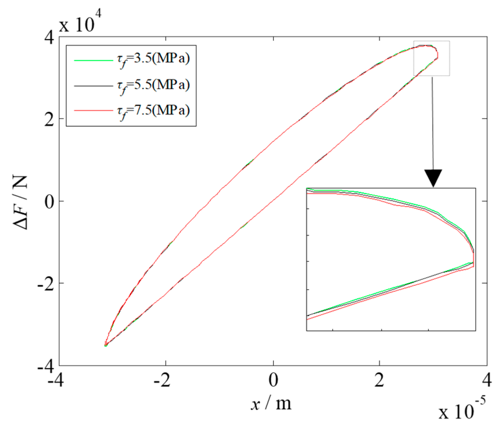
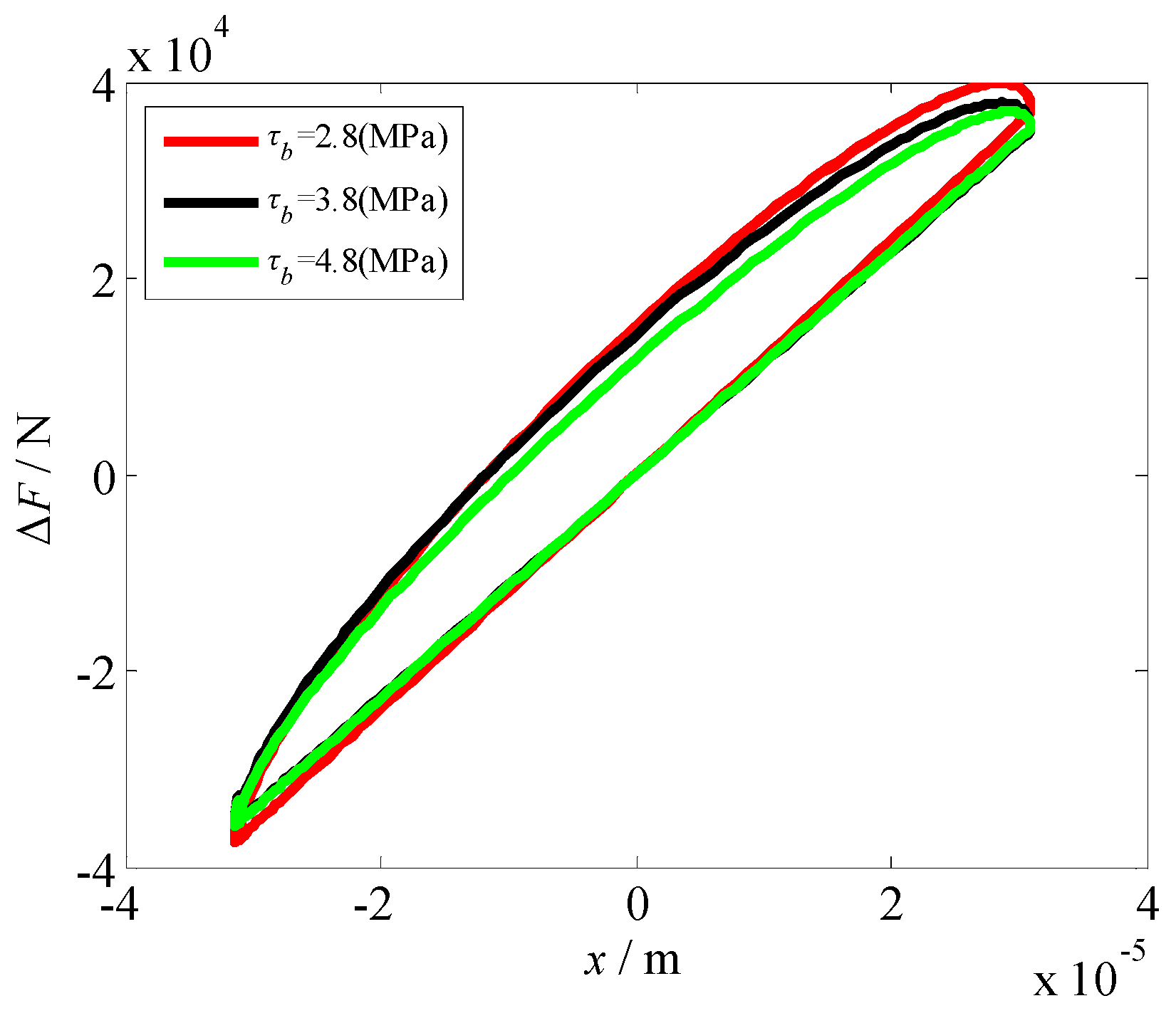
2.4. Effect of Rolling Parameters on Dynamic Rolling Force ΔF

Figure 4, Figure 5, Figure 6, Figure 7, Figure 8 and Figure 9 show the variation curves of the dynamic rolling force under different rolling parameters. The area enclosed by the hysteresis loop represents the energy dissipated by the rolling mill vibration system.
Figure 4 shows the change in the dynamic rolling force with the roll speed. As shown, with the gradual increase in the rolling speed, the area surrounded by the hysteresis loop is gradually reduced, i.e., the loss of energy is reduced. For the rolling mill vibration system, the smaller the area enclosed by the hysteresis loop, the higher the control accuracy of the vibration system. However, during actual rolling, we cannot simply increase the rolling speed, because when the rolling speed is close to a certain speed, although the hysteresis phenomenon is suppressed, it will make the vibration frequency of some parts of the rolling mill system to approach the natural frequency of the mill stand, resulting in a resonance. This will destabilize the vibration system of the rolling mill and is an important factor in restraining the rolling speed.
Figure 5 shows the variation in the dynamic rolling force with the roll radius. When the roll radius increases, the hysteresis area gradually increases, the area of the hysteresis ring enlarges, and the hysteresis phenomenon is evident.
Figure 6 shows the change in the dynamic rolling force under different entry thicknesses of the workpieces. A continuous reduction in the entry thickness will lead to a gradual decrease in the hysteresis area, and the hysteresis phenomenon also gradually weakens. Figure 7 shows the variation in the dynamic rolling force with the width of the workpiece. The width of the workpiece has no effect on the hysteresis loop area, which shows that it has little effect on the dynamic rolling force and therefore be ignored.
Figure 8 and Figure 9 show the variations in the dynamic rolling force with the front tension and back tension, respectively. As shown, the tension has little effect on the hysteresis loop, which is mainly due to the looper device installed between the stands of the rolling mill during the continuous hot rolling. Moreover, a micro-tension control is adopted, so the tension is very low, and the influence of the tension on the rolling force is minor.
The above results showed that there are different hysteresis phenomena between the dynamic rolling force and the roll vibration displacement under different rolling parameters. The hysteresis region can be reduced gradually by appropriately increasing the rolling speed and decreasing the roll radius and entry thickness of the workpiece. Therefore, the rolling parameters should be selected reasonably in actual production to reduce the hysteresis loop as much as possible and improve the control accuracy of the rolling mill.

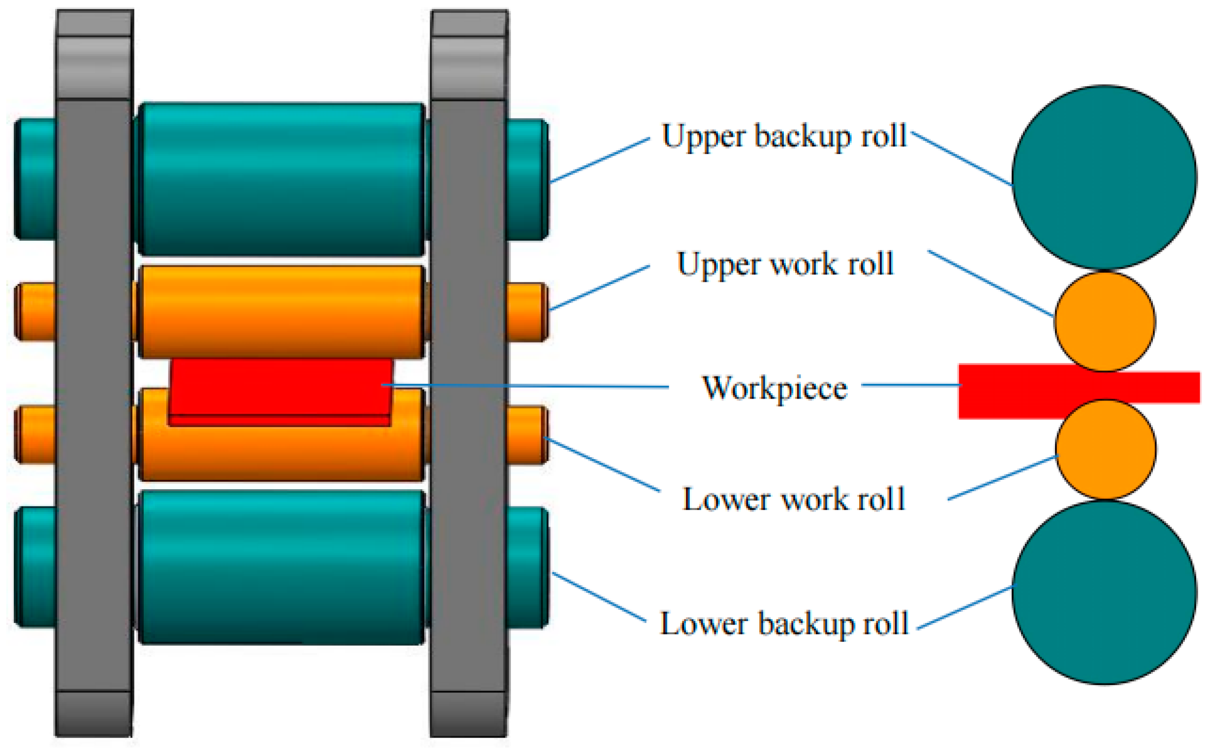
3. Hysteresis Nonlinear Dynamic Modeling of Hot Rolling Mills

Considering the effects of the dynamic rolling force with hysteresis and the parametric stiffness between the rolls, combined with the mechanical structure of a four-high hot rolling mill, a vibration model of the vertical system of the rolling mill is established, as shown in Figure 10.
In Figure 10, m1 and m3 are the equivalent masses of the upper roll and lower work roll, respectively, and m2 and m4 are the equivalent masses of the upper and lower backup rolls, respectively. x2 and x4 are the vertical vibration displacements of the upper and lower backup rolls, respectively. c1 and k1 are the equivalent damping and stiffness between the upper work roll and the upper backup roll, respectively. c2 and k2 are the equivalent damping and equivalent stiffness between the upper backup roll and the upper beam of the frame, respectively. c3 and k3 are the equivalent damping and stiffness between the lower work roll and the lower backup roll, respectively. c4 and k4 are the equivalent damping and stiffness between the lower backup roll and the lower beam of the frame, respectively.
In a rolling process, under the effect of some external periodic action, the stiffness between the rolling mill rolls exhibits a periodic fluctuation. Therefore, a parametric stiffness k0 = k′(1 − cosωt) is introduced to represent the nonlinear stiffness between the work roll and the backup roll, where k′ is the excitation stiffness, and ω is the excitation frequency.
From the vibration model shown in Figure 10, a dynamic equation for the vertical vibration system of a hot rolling mill is obtained as follows:
{ m 2 x ¨ 2 + ( c 1 + c 2 ) x ˙ 2 c 1 x ˙ 1 + k 2 x 2 [ k 1 + k ( 1 cos ω t ) ] ( x 1 x 2 ) = 0 m 1 x ¨ 1 + c 1 ( x ˙ 1 x ˙ 2 ) + [ k 1 + k ( 1 cos ω t ) ] ( x 1 x 2 ) + Δ F ( x , x ˙ ) = 0 m 3 x ¨ 3 + c 3 ( x ˙ 3 x ˙ 4 ) + [ k 3 + k ( 1 cos ω t ) ] ( x 3 x 4 ) Δ F ( x , x ˙ ) = 0 m 4 x ¨ 4 + ( c 3 + c 4 ) x ˙ 4 c 3 x ˙ 3 + k 4 x 4 [ k 3 + k ( 1 cos ω t ) ] ( x 3 x 4 ) = 0
Because of the structure of the upper and lower rolls of the rolling mill and the symmetry in the vibration characteristics of the upper and lower rolls [28], it can be considered that m1 = m3, m2 = m4, c1 = c3, c2 = c4, k1 = k3, and k2 = k4, and at the same time, x1 = −x3 and x2 = −x4. Accordingly, ΔF(x, ) in Equation (12) can be transformed into ΔF(2x1, 21). Therefore, Equation (12) can be simplified as:
{ m 1 x ¨ 1 + c 1 ( x ˙ 1 x ˙ 2 ) + [ k 1 + k ( 1 cos ω t ) ] ( x 1 x 2 ) + Δ F ( 2 x 1 , 2 x 2 ) = 0 m 2 x ¨ 2 + ( c 1 + c 2 ) x ˙ 2 c 1 x ˙ 1 + k 2 x 2 [ k 1 + k ( 1 cos ω t ) ] ( x 1 x 2 ) = 0
Equation (13) can be further simplified as:
{ x ¨ 1 + ω 1 2 x 1 + ( μ 1 + α 1 ) x ˙ 1 μ 1 x ˙ 2 β 1 x 1 cos ω t [ γ 1 + β 1 ( 1 cos ω t ) ] x 2 + ϑ 1 x 1 2 + ς 1 x ˙ 1 2 + η 1 x 1 3 + ξ 1 x ˙ 1 3 = 0 x ¨ 2 + ω 2 2 x 2 + ( μ 2 + α 2 ) x ˙ 2 α 2 x ˙ 1 β 2 x 2 cos ω t [ γ 2 + β 2 ( 1 cos ω t ) ] x 1 = 0 ,
where:
ω 1 2 = 2 a 1 + k 1 + k m 1 ,   μ 1 = c 1 m 1 ,   α 1 = 2 b 1 m 1 ,   β 1 = k m 1 ,   γ 1 = k 1 m 1 ,
ϑ 1 = 4 a 2 m 1 ,   ς 1 = 4 b 2 m 1 ,   η 1 = 8 a 3 m 1 ,   ξ 1 = 8 b 3 m 1 ,
ω 2 2 = k 2 + k 1 + k m 2 ,   μ 2 = c 1 m 2 ,   α 2 = c 2 m 2 ,   β 2 = k m 2 ,   and   γ 2 = k 1 m 2 .
Equation (14) is the dynamic equation for the hysteretic nonlinear vertical vibration of a hot rolling mill considering the effects of elastoplastic deformation hysteresis and parametric stiffness between the rolls. The dynamic behavior of the hot rolling mill rolls can be further studied and analyzed using this equation.

4. Amplitude-Frequency Characteristics of the Vertical Vibration System of the Hot Rolling Mill

A highly accurate multi-scale method is used for the approximate calculation [29]. The nonlinear term in Equation (14) is crowned with a small parameter ε, and the fast and slow time scales T0 = t and T1 = εt are introduced. Thus, we obtain:
{ d d t = D 0 + ε D 1 + d 2 d t 2 = D 0 2 + 2 ε D 0 D 1 + ,
where Dn (n = 0,1) is a partial differential sign and is written as: Dn = ∂/∂Tn. Let the solution to Equation (15) be:
{ x 1 ( t ) = x 11 ( T 0 , T 1 ) + ε x 12 ( T 0 , T 1 ) x 2 ( t ) = x 21 ( T 0 , T 1 ) + ε x 22 ( T 0 , T 1 )
We substitute Equation (15) and Equation (16) into Equation (14), and let the coefficients of the same power of ε be equal. Thus, we obtain the zero-order approximate equation:
{ D 0 2 x 11 + ω 1 2 x 11 = 0 D 0 2 x 21 + ω 1 2 x 21 = 0
The first-order approximate equation is as follows:
{ D 0 2 x 12 + ω 1 2 x 12 = 2 D 0 D 1 x 11 ( μ 1 + α 1 ) D 0 x 11 + μ 1 D 0 x 21 + β 1 x 11 cos ω t + [ γ 1 + β 1 ( 1 cos ω t ) ] x 21 ϑ 1 x 11 2 ς 1 ( D 0 x 11 ) 2 η 1 x 11 3 ξ 1 ( D 0 x 11 ) 3 D 0 2 x 22 + ω 1 2 x 22 = 2 D 0 D 1 x 21 ( μ 2 + α 2 ) D 0 x 21 + α 2 D 0 x 11 + β 2 x 21 cos ω t + [ γ 2 + β 2 ( 1 cos ω t ) ] x 11
Let the complex solution to Equation (17) be:
{ x 11 = A ( T 1 ) e i ω 1 T 0 + A ¯ ( T 1 ) e i ω 1 T 0 x 21 = B ( T 1 ) e i ω 2 T 0 + B ¯ ( T 1 ) e i ω 2 T 0 ,
where A(T1) and B(T1) are undetermined complex functions, and A ¯ ( T 1 ) and B ¯ ( T 1 ) are the conjugate complex numbers of A(T1) and B(T1), respectively. Substituting Equation (19) into Equation (18) yields:
{ D 0 2 x 12 + ω 1 2 x 12 = [ i ω 1 ( 2 D 1 A + μ 1 A + α 1 A ) ( 3 i ξ 1 ω 1 3 + 3 η 1 ) A 2 A ¯ ] e i ω 1 T 0 + B ( i ω 2 μ 1 + γ 1 + β 1 ) e i ω 2 T 0 + β 1 2 ( A e i ( ω + ω 1 ) T 0 + A ¯ e i ( ω ω 1 ) T 0 ) β 1 2 ( B e i ( ω + ω 2 ) T 0 + B ¯ e i ( ω ω 2 ) T 0 ) + ( ϑ 1 + ς 1 ω 1 2 ) A 2 e 2 i ω 1 T 0 + ( η 1 i ξ 1 ω 1 3 ) A 3 e 3 i ω 1 T 0 + c c D 0 2 x 22 + ω 2 2 x 22 = i ω 2 ( 2 D 1 B + μ 2 B + α 2 B ) e i ω 2 T 0 + A ( i ω 1 α 2 + γ 2 + β 2 ) e i ω 1 T 0 + β 2 2 ( B e i ( ω + ω 2 ) T 0 + B ¯ e i ( ω ω 2 ) T 0 ) β 2 2 ( A e i ( ω + ω 1 ) T 0 + A ¯ e i ( ω ω 1 ) T 0 ) + c c ,
where cc is the conjugate complex number of the items on the left of the expression. On the right side of Equation (20), we have the terms e i ω 1 T 0 and e i ω 2 T 0 . When ω1ω2, the duration term is generated, and an internal resonance of the rolling mill system will occur. Moreover, we have e i ( ω ω 1 ) T 0 and e i ( ω ω 2 ) T 0 . The duration term can also be generated when ω ≈ 2ω1 or ω ≈ 2ω2, which makes the rolling mill system to produce 1/2 subharmonic resonance.

4.1. Solution of the Subharmonic Resonance Response

The subharmonic resonance of the rolling mill vibration system is considered, and we take ω = 2ω1 + δ, where δ is the tuning parameter; in this case, ω2 is far away from ω1. By eliminating the duration term in Equation (20), we can obtain:
{ i ω 1 ( 2 D 1 A + μ 1 A + α 1 A ) ( 3 i ξ 1 ω 1 3 + 3 η 1 ) A 2 A ¯ + β 1 2 A ¯ e i δ T 1 = 0 i ω 2 ( 2 D 1 B + μ 2 B + α 2 B ) = 0
The polar coordinates of A(T1) and B(T1) are introduced as follows:
{ A ( T 1 ) = a ( T 1 ) e i φ 1 ( T 1 ) / 2 B ( T 1 ) = b ( T 1 ) e i φ 2 ( T 1 ) / 2 ,
where a, b, φ1, and φ2 are all real functions of T1. In this paper, a is the vibration amplitude of the work roll, and b is the vibration amplitude of the backup roll. By substituting Equation (22) into Equation (21) and separating the real part from the imaginary, the average equation for the rolling mill vertical vibration system in polar coordinates can be obtained as:
{ a ˙ = 1 2 ( μ 1 + α 1 ) a 3 8 ξ 1 ω 1 2 a 3 + β 1 4 ω 1 a sin θ a θ ˙ = δ a 3 8 ω 1 η 1 a 3 β 1 4 ω 1 a cos θ b ˙ = 1 2 ( μ 2 + α 2 ) b b φ ˙ 2 = 0 ,
where θ = δT1φ1; for a steady-state response, we have a ˙ = b ˙ = 0 and θ ˙ = 0 ; thus, b = 0. By eliminating θ in Equation (23), we can obtain the 1/2 subharmonic resonance amplitude-frequency response equation for the rolling mill rolls based on the elastoplastic hysteresis deformation of the workpiece:
[ 1 2 ( μ 1 + α 1 ) + 3 ξ 1 8 ω 1 2 a 2 ] 2 + ( δ 3 η 1 8 a 2 ) 2 = ( β 1 4 ω 1 ) 2
From Equation (24), we found that the dimensionless parameters affecting the subharmonic resonance of the rolling mill rolls are μ1, α1, β1, and η1. Their corresponding rolling process parameters are the structural damping c1, linear damping b1, parametric stiffness k0, and nonlinear stiffness a3.

4.2. Solution of Internal Resonance Response

When the natural frequency of the work and backup rolls, the parametric excitation frequency, and the natural frequency of the work roll are composed of a certain frequency, it will result in an internal resonance of the rolling mill rolls. In this paper, ω1 = ω2 + εδ1 and ω = 2ω1 + εδ, where δ1 is the tuning parameter. To eliminate the duration term in Equation (20), the following must be satisfied:
{ i ω 1 ( 2 D 1 A + μ 1 A + α 1 A ) ( 3 i ξ 1 ω 1 3 + 3 η 1 ) A 2 A ¯ + B ( i ω 2 μ 1 + γ 1 + β 1 ) e i δ 1 T 1 + β 1 2 A ¯ e i δ T 0 = 0 i ω 2 ( 2 D 1 B + μ 2 B + α 2 B ) + A ( i ω 1 α 2 + γ 2 + β 2 ) e i δ 1 T 1 = 0
By substituting Equation (22) into Equation (25) and separating the real and imaginary parts, we can obtain the average equation in the polar coordinates:
{ a ˙ = 1 2 ( μ 1 + α 1 ) a 3 8 ξ 1 ω 1 3 a 3 b 2 ω 1 [ ω 2 μ 1 cos θ 2 ( γ 1 + β 1 ) sin θ 2 ] + β 1 4 ω 1 a sin θ 1 a ( θ ˙ 1 + θ ˙ 2 ) = ( δ δ 1 ) a 3 8 ω 1 η 1 a 3 + b 2 ω 1 [ ω 2 μ 1 sin θ 2 + ( γ 1 + β 1 ) cos θ 2 ] β 1 4 ω 1 a cos θ 1 b ˙ = 1 2 ( μ 2 + α 2 ) b a 2 ω 2 [ ω 1 μ 2 cos θ 2 + ( γ 2 + β 2 ) sin θ 2 ] b θ ˙ 2 = δ 1 b a 2 ω 2 [ ω 1 μ 2 sin θ 2 + ( γ 2 + β 2 ) cos θ 2 ] ,
where θ1 = δT0 − 2φ1, and θ2 = φ2φ1δ1T0. When the internal resonance system of the rolling mill moves periodically, a ˙ = b ˙ = θ ˙ 1 = θ ˙ 2 = 0 in Equation (26). By eliminating θ1 and θ2 in Equation (26), the amplitude-frequency response equations of the internal resonance of the rolling mill rolls under an elastoplastic hysteresis deformation of the workpiece can be obtained as follows:
{ [ 1 2 N 1 a 3 8 ξ 1 ω 1 3 a 3 b 2 2 ω 1 P 1 ] 2 + [ N 2 a + 3 η 1 8 ω 1 a 3 b 2 2 ω 1 P 2 ] 2 = β 1 2 a 2 16 ω 1 2 [ 1 4 ( μ 2 + α 2 ) 2 + δ 1 2 ] b 2 = a 2 4 ω 2 2 ( μ 2 2 ω 1 2 + M 2 2 ) ,
where
P 1 = ω 2 [ ( μ 2 + α 2 ) ( M 1 M 2 μ 1 μ 2 ω 1 ω 2 ) + 2 δ 1 ( μ 1 ω 2 M 2 μ 2 ω 1 M 1 ) ] μ 2 2 ω 1 2 + M 2 2 ,
P 2 = ω 2 [ ( μ 2 + α 2 ) ( μ 1 ω 2 M 2 + μ 2 ω 1 M 1 ) + 2 δ 1 ( M 1 M 2 + μ 1 μ 2 ω 1 ω 2 ) ] μ 2 2 ω 1 2 + M 2 2 ,
M 1 = γ 1 + β 1 ,   M 2 = γ 2 + β 2 ,   N 1 = μ 1 + α 1 ,   and   N 2 = δ δ 1 .

4.3. Amplitude-Frequency Characteristics of the Subharmonic and Internal Resonances of the Rolling Mill Rolls

Table 3 lists the relevant process parameters of the 1780 mm hot rolling mill. Combined with the data listed in Table 1 and Table 2, the amplitude-frequency response characteristics of the rolling mill vibration system under the action of the elastoplastic hysteresis deformation were analyzed by conducting a numerical simulation. Figure 11, Figure 12, Figure 13 and Figure 14 show the subharmonic resonance amplitude-frequency curves of the rolling mill under different process parameters. Figure 15, Figure 16 and Figure 17 show the internal resonance amplitude-frequency curves of the rolling mill with the change in the parametric stiffness.
Figure 11 shows the subharmonic resonance amplitude-frequency curves of the rolling mill system with the change in the structural damping c1 between the work and backup rolls of the rolling mill. With the decrease in c1, the vibration amplitude of the work roll increases; however, the resonance region is gradually reduced, the bending degree of the vibration curve remains unchanged, and there is no jumping phenomenon, which shows that the vibration system is in a relatively stable state with the change in c1.
Figure 12 shows the amplitude-frequency response curves of the rolling mill system with the change in the linear damping b1 in the dynamic rolling force with hysteresis. With the change in the linear damping, the vibration amplitude and resonance region of the vertical system of the rolling mill change slightly, indicating that the linear damping has little influence on the vibration of the system. This is because a comparison between the linear damping b1 and the structural damping c1 between the rolls shows that the linear damping value is lower. In actual rolling, the structural damping has a major effect on the rolling mill system.
Figure 13 shows the subharmonic resonance amplitude-frequency curves of the rolling mill rolls with the change in the parametric stiffness k0. The parametric stiffness affects the natural frequency of the work roll; moreover, with the increase in k0, the vibration amplitude increases, the backbone curve shifts to the right, the resonance region widens, and the influence of the parametric stiffness on the amplitude-frequency curve is evident. Figure 14 depicts the variation law of the subharmonic resonance of the rolling mill system with the change in the nonlinear stiffness term a3 corresponding to the dynamic rolling force. With the increase in a3, the area of the resonance region and the vibration amplitude increase rapidly. After increasing to a certain value, there is a jump, which destabilizes the system. The parametric stiffness and nonlinear stiffness have a significant influence on the vibration of the rolling mill system. In an actual rolling process, the two parameters should be appropriately selected to ensure a smooth operation of the hot rolling mill.
Figure 15 shows the variation law of the internal resonance amplitude-frequency relationship of the rolling mill system with the change in parametric stiffness k0. In the figure legend, letters a and b represent the vibration amplitudes of the work roll and backup roll, respectively. The three subgraphs have two common characteristics:
  • When vibration occurs, there will be two vibration regions on the vibration curve of the work and backup rolls. This is because the internal resonance of the rolling mill roll occurs at this time. Moreover, we verified that the resonance relationships ω1 = ω2 + εδ1 and ω = 2ω1 + εδ are correct.
  • Comparing the two curves in each image, it can be found that the vibration amplitude of the work and backup rolls alternately increase or decrease, and the vibration energy is constantly exchanged between the work and backup rolls, which is one of the unique phenomena of the internal resonance.
Figure 15a shows the variation law of the internal resonance amplitude-frequency relationship of the rolling mill system when the parameter excitation stiffness k0 = 1.75 × 10¹⁰ N/m. When the tuning parameter δ is in the range of −20 Hz < δ < −5 Hz, the vibration amplitudes of the work and backup rolls increase gradually, and the rolling mill rolls are in a relatively stable state. With the increase in δ, the vibration amplitude increases sharply. At this time, the rolling mill rolls enter the resonance region; in the region of −5 Hz < δ < 19 Hz, the vibration amplitudes of the two rolls increase or decrease alternately, leaving behind different degrees of light and dark stripes on the workpiece surface, thus affecting the surface quality and accuracy of the workpiece. Therefore, in practice, appropriate measures should be taken to avoid the resonance area and ensure a smooth operation of the rolling mill. With the further increase in δ, i.e., when δ > 19 Hz, the amplitudes of the work and backup rolls gradually decrease, and the rolling mill tends to be stable. This is because the vibration frequency between the rolling mill rolls and the external excitation frequency are far away from each other, thus avoiding resonance.
Figure 15b shows the amplitude-frequency curves of the internal resonance of the rolling mill rolls when the parametric excitation stiffness k0 = 1.60 × 10¹⁰ N/m. The vibration amplitudes of the work and backup rolls decrease, and the change trend in the vibration curve and the resonance phenomenon are similar to those shown in Figure 15a. Figure 15c shows the variation curve of the internal resonance with further reduction in the parametric stiffness. When k0 = 1.45 × 10¹⁰ N/m, the vibration curves of the two rollers shift to the left, the resonance region is reduced, and resonance occurs only in the region of −10 Hz < δ < 10 Hz. This shows that with the decrease in the parametric excitation stiffness, the stable area of the rolling mill rolls gradually increases, which is conducive to the normal operation of the rolling mill. However, notably, in the range of −8.5 Hz < δ < −6.5 Hz, the vibration amplitude of the backup roll is high, and there are multiple solutions on the vibration curve, resulting in a jump phenomenon, which will lead to the severe vibration of the backup roll. Therefore, it is necessary to select appropriate parameters to avoid the vibration range during actual rolling, so as to reduce the effect of resonance on the system.

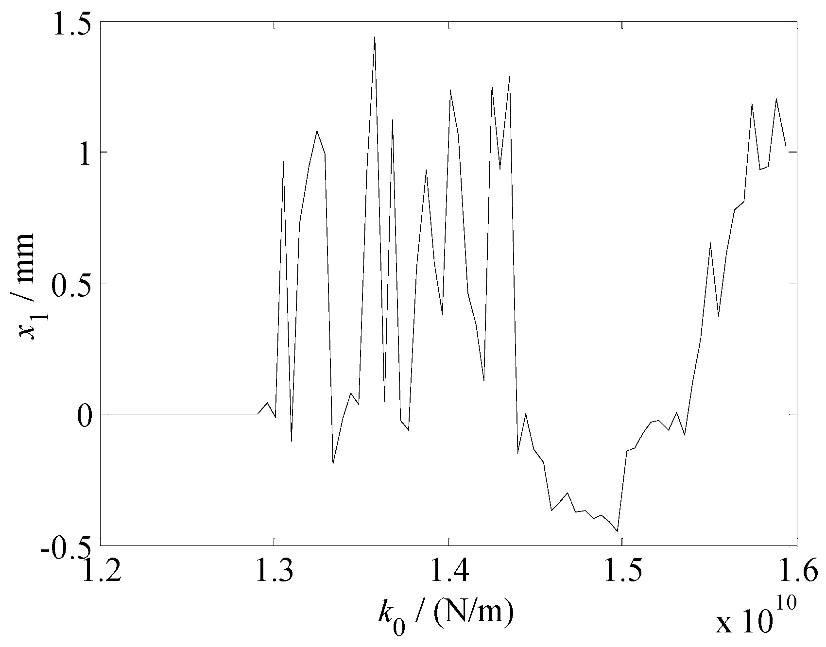
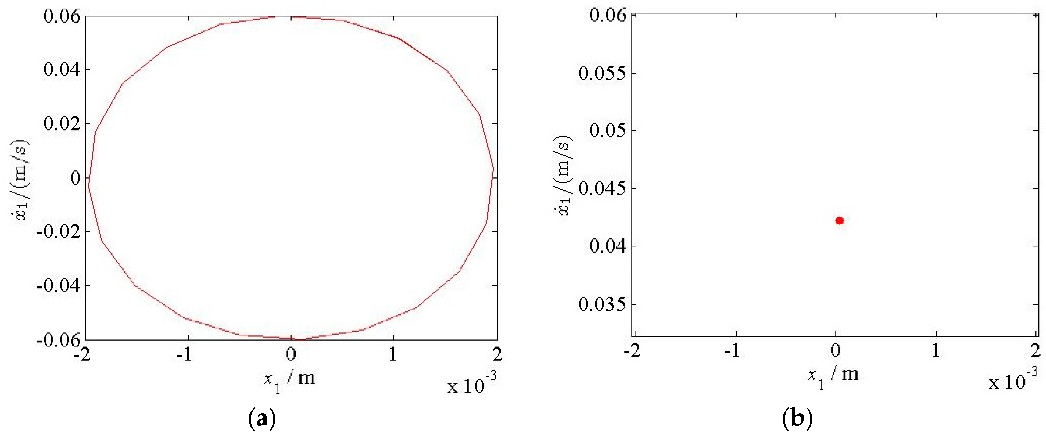
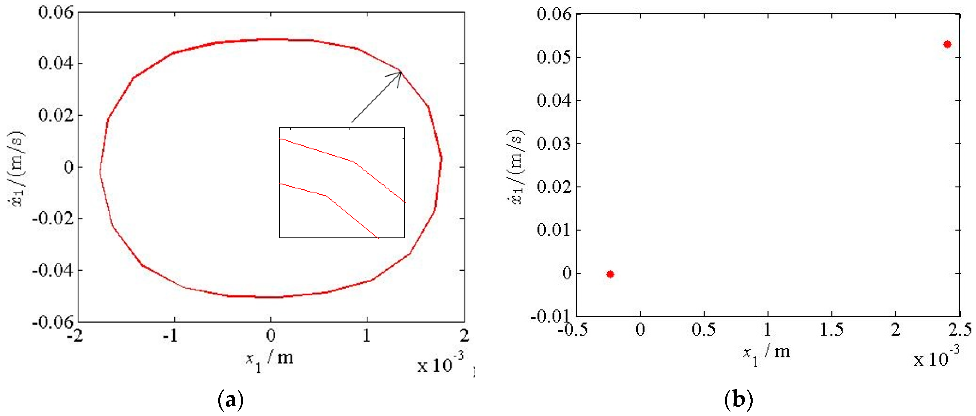
5. Chaotic Characteristics of the Vertical Vibration System of the Hot Rolling Mill

In this study, based on the chaos vibration theory, the nonlinear dynamic behavior of hot rolling mill rolls under the influence of hysteretic deformation of the workpiece was studied. This was done to obtain the parameter region and critical value that causes rolling mill vibration, so as to avoid this vibration in actual production and ensure a stable operation of the rolling mill. According to Equation (14), the numerical simulation was carried out using the relevant data provided in the paper. The results are shown in Figure 16, Figure 17, Figure 18, Figure 19, Figure 20, Figure 21, Figure 22, Figure 23 and Figure 24.
Figure 16 shows the chaotic vibration diagram of the work roll of the hot rolling mill with the change in the parametric stiffness k0. Figure 17 shows the corresponding maximum Lyapunov exponent curve. Figure 18, Figure 19 and Figure 20 show the phase trajectories and Poincare sections of the work rolls with the change in parametric stiffness k0.
Figure 16 shows that with the change in parametric stiffness k0, the overall vibration change trend of the work roll is as follows: period one movement → period four movement → chaotic motion → degenerate to period one motion → period doubling motion → chaotic motion. According to the nonlinear vibration theory, the Lyapunov exponent is an important index to judge, whether a system is in chaos. When the Lyapunov exponent is positive and the motion is repeated, the vibration system is said to be in a chaotic motion. When it is zero or negative, the vibration system is in a periodic motion. The change in the Lyapunov exponent curve, as shown in Figure 17, is consistent with that shown in Figure 16, which verifies the correctness of the chaotic vibration of the work roll.
Figure 16 shows that when the parametric stiffness k0 < 1.3 × 10¹⁰ N/m, the vibration of the work roll is a single-cycle motion, the vibration displacement is small, and the system is in a stable state. The corresponding phase trajectory is a closed curve (Figure 18a), and the corresponding Poincare section is a fixed point (Figure 18b). With the increase in parametric stiffness k0, the vibration displacement increases sharply; the system evolves into period four movement and then enters a chaotic state. At this time, the work roll has no regular vibration, which affects the normal operation. This is because an increase in the parametric excitation stiffness changes the natural frequency of the work roll and makes the external excitation frequency approach the changed natural frequency, resulting in resonance, which leads to a chaotic motion. When parameter excitation stiffness k0 = 1.44 × 10¹⁰ N/m, the vibration system degenerates into period one motion, which indicates that the external excitation frequency is far away from the natural frequency of the work roll. With the further increase in the parametric excitation stiffness, when k0 = 1.51 × 10¹⁰ N/m, the vibration system enters a period doubling motion, and the corresponding phase trajectory is a closed curve formed after two cycles (Figure 19a), and the Poincare section can be represented by two fixed points (Figure 19b). The appearance of a period-doubling bifurcation indicates chaos. When k0 = 1.542 × 10¹⁰ N/m, the vibration form of the work roll moves from a period-doubling motion to a chaotic motion. The phase trajectory of the chaotic motion is always an unclosed loop curve (Figure 20a), and the Poincare section is composed of many features with a self-similar structure (Figure 20b). In an actual rolling process, the chaotic vibration region can be avoided by changing the rolling and process parameters, so as to make the rolling mill run smoothly.
Figure 21 shows the chaotic vibration diagram of the backup roll with the change in parametric stiffness k0. Figure 22 shows the corresponding maximum Lyapunov exponent curve.
Figure 21 shows that the main forms of the vibration state of the backup roll are periodic and chaotic. When parametric stiffness k0 < 1.44 × 10¹⁰ N/m, the vibration state is a period one motion, and its corresponding Lyapunov exponent is zero or negative. The corresponding phase trajectory and Poincare section are shown in Figure 23. Although the motion is periodic, there are many jumps in the vibration displacement. This is because of the hysteresis characteristics between the rolling force and the vibration displacement during the elastoplastic deformation of the workpiece, which leads to varying rolling forces for the same vibration displacement, resulting in a jump in the vibration displacement. When parametric stiffness k0 = 1.45 × 10¹⁰ N/m, the vibration displacement of the backup roll increases sharply, and the system has paroxysmal chaos, which also verifies the jump phenomenon of the backup roll in the range of −8.5 Hz < δ < −6.5 Hz when the parameter excitation stiffness k0 = 1.45 × 10¹⁰ N/m, as shown in Figure 15c. Subsequently, the vibration system enters a chaotic state; Figure 24 shows the corresponding phase trajectory and Poincare section. When k0 = 1.542 × 10¹⁰ N/m, the vibration system degenerates into a period one motion, and the work roll of the rolling mill starts to run stably.
Comparing Figure 16 and Figure 21, we find that the work roll exhibits a chaotic motion in the parametric stiffness range of 1.3 × 10¹⁰ N/m < k0 < 1.44 × 10¹⁰ N/m and k0 > 1.542 × 10¹⁰ N/m, and the vibration state is steady in the other regions. In comparison, the vibration pattern of the backup roll is just opposite to that of the work roll. The motion is chaotic in the region of 1.44 × 10¹⁰ N/m < k0 < 1.542 × 10¹⁰ N/m and periodic in the other regions. This motion pattern is consistent with the vibration phenomenon of the internal resonance shown in Figure 15, i.e., the vibration amplitudes of the work and backup rolls increase and decrease alternately, and vibration energy is continuously exchanged between the two rollers. This shows that under the influence of the elastoplastic hysteresis deformation, with the change in the external excitation frequency, there is a significant possibility of an internal resonance between the work and backup rolls of the rolling mill, thereby increasing the vibration amplitude and deviating from the vibration law. This affects the surface quality and accuracy of the workpiece. Failing to take timely restraining measures may even lead to steel breakage.

6. Conclusions and Observations

  • Considering the influence of the nonlinear deformation of a workpiece undergoing elastoplastic hysteresis in a rolling process, a dynamic rolling force model with the hysteresis effect was established, providing a theoretical basis for studying rolling mill vibration. Based on the actual rolling parameters of a 1780 mm hot rolling mill, the hysteresis characteristics between the dynamic rolling force and the vibration displacement under different rolling parameters were analyzed by conducting simulations. The hysteresis phenomenon of the rolling mill rolls could be weakened gradually by appropriately increasing the rolling speed and reducing the roll radius and entry thickness, whereas the rolling width, front tension, and back tension have little effect on the hysteresis characteristics.
  • We analyzed the subharmonic resonance characteristics of the rolling mill rolls by varying the structural damping, parametric stiffness, linear damping term, and nonlinear stiffness term. Measures to restrain the vibration of the rolling mill were provided in terms of the vibration amplitude, resonance area, and vibration curve deviation. Moreover, as evident characteristics of the internal resonance of the rolling mill rolls, the vibration amplitudes of the work and backup rolls increase and decrease alternately, and there is an evident energy exchange process. With the change in the parametric stiffness, the internal resonance system exhibits a jump phenomenon, thus destabilizing the rolling mill vibration system.
  • The chaotic vibration characteristics of the work and backup rolls with the change in the parametric stiffness were analyzed and verified using a chaos diagram, maximum Lyapunov exponent, phase trajectory, and Poincare section. The vibration system exhibits periodic, period doubling, and chaotic motions, and it transitions from one form to another, which is one of the reasons for the occurrence of light and dark stripes in the rolled pieces. We also determined the critical value and value range of the parametric stiffness in the presence of chaotic motion, thus providing an effective guidance for adjusting the parametric stiffness between the rolls when the rolling mill vibration is suppressed.
  • In the research process, the modeling and theoretical analysis of the traditional rolling mill vibration mechanism simplify many factors in actual production, resulting in a large error between the theoretical analysis and the actual measurement. A single model cannot explain the cause of rolling chatter completely, and it is not capable of generalization. In recent years, machine learning has been widely used in the industrial field, where deep learning can unearth the deep-seated characteristics that affect the vibration of a rolling mill from a large amount of data and can thus effectively solve problems such as high dimensionality, nonlinearity, and high coupling. The follow-up research will use deep learning to address the vibration phenomenon of rolling mills under complex conditions.

Author Contributions

Conceptualization, data curation and writing—original draft, R.P.; project administration, software, supervision, writing—review and editing, P.S.; supervision, writing—review and editing, X.Z. All authors have read and agreed to the published version of the manuscript.

Funding

This research was funded by the National Natural Science Foundation of China (grant number: 61973262), and the Natural Science Foundation of Hebei Province (grant number: E2019203146), and the Graduate Innovation Funding Project of Hebei Province (grant number: CXZZBS2021136).

Data Availability Statement

The structural and technological data of rolling mill used to support the findings of this study are included within the article.

Conflicts of Interest

The authors declare no conflict of interest.

Nomenclature

RRadius of the work roll
BWidth of the workpiece
H0Entry thickness
h0Exit thickness
τfFront tension
τbBack tension
vRRotation speed of the roll
vyVertical reduction speed
lcHorizontal projection length of the contact arc
αBite angle
c1Equivalent damping between the upper work roll and the upper backup roll
c2Equivalent damping between the upper backup roll and the upper beam of the frame
c3Equivalent damping between the lower work roll and the lower backup roll
c4Equivalent damping between the lower backup roll and the lower beam of the frame
k1Equivalent stiffness between the upper work roll and the upper backup roll
k2Equivalent stiffness between the upper backup roll and the upper beam of the frame
k3Equivalent stiffness between the lower work roll and the lower backup roll
k4Equivalent stiffness between the lower backup roll and the lower beam of the frame
x1, x2Vertical vibration displacement of the upper work roll and upper backup roll
x3, x4Vertical vibration displacement of the lower work roll and lower backup roll
m1, m2Equivalent mass of the upper work roll and upper backup roll
m3, m4Equivalent mass of the lower work roll and lower backup roll
a1, a2, a3Equivalent stiffness coefficients corresponding of dynamic rolling force
b1, b2, b3Equivalent damping coefficients corresponding of dynamic rolling force
ΔFDynamic rolling force variation
φmIncluded angle at a distance of m from the center line of the work roll
kExcitation stiffness
tDeformation temperature
ωExcitation frequency
εSmall parameter

References

  1. Hu, P.H.; Ehmann, K.F. Stability Analysis of Chatter on a Tandem Rolling Mill. J. Manuf. Process. 2000, 2, 217–224. [Google Scholar] [CrossRef]
  2. Niziol, J.; Swiatoniowski, A. Numerical Analysis of the Vertical Vibration of Rolling Mill and Their Negative Effect on the Sheet Quality. J. Mater. Process. Tech. 2005, 162, 546–550. [Google Scholar] [CrossRef]
  3. Yan, X.Q.; Sun, Z.H.; Chen, W.Q. Vibration Control in Thin Slab Hot Strip Mills. Ironmak. Steelmak. 2011, 38, 309–313. [Google Scholar] [CrossRef]
  4. Efrain, U. Identification and Countermeasures to Resolve Hot Mill Chatter. AISE. Steel. Tech. 2001, 78, 48–52. [Google Scholar]
  5. Fan, X.B.; Zang, Y.; Jin, K. Rolling Process and Its Influence Analysis on Hot Continuous Rolling Mill Vibration. Appl. Phys. A 2016, 122, 1008. [Google Scholar] [CrossRef]
  6. Sun, J.L.; Peng, Y.; Liu, H.M. Non-Linear Vibration and Stability of Moving Strip with Time-Dependent Tension in Rolling Process. J. Iron. Steel. Res. Int. 2010, 17, 11–15, 20. [Google Scholar] [CrossRef]
  7. Valigi, C.M.; Papini, S. Analysis of Chattering Phenomenon in Industrial S6-High Rolling Mill. Diagnostyka 2013, 14, 3–8. [Google Scholar]
  8. Papini, S.; Valigi, C.M. Analysis of Chattering Phenomenon in Industrial S6-High Rolling Mill. Part II Experimental Study. Diagnostyka 2016, 17, 27–32. [Google Scholar]
  9. Kozhevnikov, A.; Bolobanova, N.; Simirnov, A. Chatter Prevention in Stands of Continuous Cold Rolling Mills. Metallurgy 2020, 59, 55–58. [Google Scholar]
  10. Pawelski, O.; Rasp, W.; Zwick, W.; Nettelbeck, H.J.; Steinhoff, K. The Influence of Different Work-Roll Texturing Systems on the Development of Surface Structure in the Temper Rolling Process of Steel Sheet Used in the Automotive Industry. J. Mater. Process. Tech. 1994, 45, 215–222. [Google Scholar] [CrossRef]
  11. Lackinger, C.V.; Nettelbeck, H.J.; Oemkes, H. The New Yandem Mill at Thyssenkrupp Stahl’s Beeckerwerth Cold Strip. Stahl Und Elsen 2002, 122, 25–32. [Google Scholar]
  12. Yarita, I.; Furukawa, K.; Seino, Y. An Analysis of Chattering in Cold Rolling of Ultra Thin Gauge Steel Strip. T. ISU 1979, 19, 110. [Google Scholar]
  13. Youne, M.A.; Shahtout, M.; Damir, M.N. A Parameters Design Approach to Improve Product Quality and Equipment Performance in Hot Rolling. J. Mater. Process. Tech. 2006, 17, 83–92. [Google Scholar] [CrossRef]
  14. Swiatoniowski, A.; Bar, A. Parametrical Excitement Vibration in Tandem Mills—Mathematical Model and Its Analysis. J. Mater. Process. Tech. 2003, 134, 214–224. [Google Scholar] [CrossRef]
  15. Zhang, G.M.; Xiao, H.; Wang, C.H. Three-Dimensional Model for Strip Hot Rolling. J. Iron. Steel. Res. Int. 2006, 13, 23–26. [Google Scholar] [CrossRef]
  16. Fan, X.B.; Zang, Y.; Jin, K. Research on Strip Hysteretic Behavior and Mill Vertical Vibration System Nonlinear Dynamics. Appl. Phys. A 2016, 122, 1–12. [Google Scholar] [CrossRef]
  17. Sims, R.B. The Calculation of Roll Force and Torque in Hot Rolling Mills. Proc. Inst. Mech. Eng. 1954, 168, 191–200. [Google Scholar] [CrossRef]
  18. Jia, C.Y.; Shan, X.Y.; Niu, Z.P. High Precision Prediction of Rolling Force Based on Fuzzy and Nerve Method for Cold Tandem Mill. J. Iron. Steel. Res. Int. 2008, 15, 23–27. [Google Scholar] [CrossRef]
  19. Dong, Y.G.; Zhang, W.Z.; Song, J.F. Theoretical and Experimental Research on Rolling Force for Rail Hot Tolling by Universal Mill. J. Iron. Steel. Res. Int. 2010, 17, 27–32. [Google Scholar] [CrossRef]
  20. Bagheripoor, M.; Bisadi, H. An Investigation on the Roll Force and Torque Fluctuations During Hot Strip Rolling Process. Prod. Manu. Res. 2014, 2, 128–141. [Google Scholar] [CrossRef] [Green Version]
  21. Wu, S.L.; Shao, Y.M.; Wang, L.M.; Yuan, Y.L.; Mechefske, C.K. Relationship between Chatter Marks and Rolling Force Fluctuation for Twenty-High Roll Mill. Eng. Fail. Anal. 2015, 55, 87–99. [Google Scholar] [CrossRef]
  22. Feng, X.W.; Wang, X.C.; Yang, Q.; Sun, J.Q. Analysis of Rate Dependency on Roll Force Calculation During Hot Strip Rolling Based on Karman Equation. Adv. Mech. Eng. 2019, 11, 1–8. [Google Scholar] [CrossRef]
  23. Li, S.; Wang, Z.G.; Guo, Y.F. A Novel Analytical Model for Prediction of Rolling Force in Hot Strip Rolling Based on Tangent Velocity Field and MY Criterion. J. Manu. Process. 2019, 47, 202–210. [Google Scholar] [CrossRef]
  24. Kazeminezhad, M.; Karimi, T.A. Calculation of the Rolling Pressure Distribution and Force in Wire Flat Rolling Process. J. Mater. Process. Tech. 2006, 171, 253–258. [Google Scholar] [CrossRef]
  25. Peng, R.R.; Zhang, X.Z.; Shi, P.M. Coupled Vibration Behavior of Hot Rolling Mill Rolls Under Multi-Nonlinear Effects. Shock Vib. 2020, 2020, 6104028. [Google Scholar]
  26. Zhang, S.H.; Deng, L.; Zhang, Q.Y.; Li, Q.H.; Hou, J.X. Modeling of Rolling Force of Ultra-Heavy Plate Considering the Influence of Deformation Penetration Coefficient. Int. J. Mech. Sci. 2019, 159, 373–381. [Google Scholar] [CrossRef]
  27. Sun, Y.K. Modelling and Control of Hot Tandem Rolling; Metallurgical Industry Publishing House: Beijing, China, 2002. [Google Scholar]
  28. Hu, P.H.; Zhao, H.Y.; Ehmann, K.F. Third-Octave-Mode Chatter in Rolling. Part 1: Chatter Model. Proc. Inst. Mech. Eng. Part B J. Eng. Manu. 2006, 220, 1267–1277. [Google Scholar] [CrossRef]
  29. Nayfeh, A.H. Perturbation Methods; Wiley-InterScience: New York, NY, USA, 1973. [Google Scholar]
Figure 1. Structure diagram of a hot rolling mill.
Metals 11 00869 g001
Figure 2. Diagram of the elastoplastic deformation process of a workpiece. Plastic deformation zone (I) and elastic deformation zone (II).
Metals 11 00869 g002
Figure 3. Hysteresis loop of the elastoplastic deformation of the workpiece.
Metals 11 00869 g003
Figure 4. Variation in the dynamic rolling force ΔF with rolling speed vR.
Metals 11 00869 g004
Figure 5. Variation in the dynamic rolling force ΔF with roll radius R.
Metals 11 00869 g005
Figure 6. Variation in the dynamic rolling force ΔF with entry thickness H0.
Metals 11 00869 g006
Figure 7. Variation in the dynamic rolling force ΔF with width B of the workpiece.
Metals 11 00869 g007
Figure 8. Variation in the dynamic rolling force ΔF with front tension τf.
Metals 11 00869 g008
Figure 9. Variation in the dynamic rolling force ΔF with back tension τb.
Metals 11 00869 g009
Figure 10. Vibration model of hot rolling mill rolls under a dynamic rolling force.
Metals 11 00869 g010
Figure 11. Amplitude-frequency curves of the subharmonic resonance of the rolling mill with the change in structural damping c1.
Metals 11 00869 g011
Figure 12. Amplitude-frequency curves of the subharmonic resonance of the rolling mill with the change in linear damping b1.
Metals 11 00869 g012
Figure 13. Amplitude-frequency curves of the subharmonic resonance of the rolling mill with the change in parametric stiffness k0.
Metals 11 00869 g013
Figure 14. Amplitude-frequency curves of the subharmonic resonance of the rolling mill with the change in nonlinear stiffness a3.
Metals 11 00869 g014
Figure 15. Amplitude-frequency curve of the internal resonance of the rolling mill rolls with the change in parametric stiffness k0: (a) k0 = 1.75 × 10¹⁰ Hz; (b) k0 = 1.60 × 10¹⁰ Hz; (c) k0 = 1.45 × 10¹⁰ Hz.
Metals 11 00869 g015
Figure 16. Chaotic diagram of the work roll with the change in parametric stiffness k0.
Metals 11 00869 g016
Figure 17. Maximum Lyapunov exponent curve of the work roll with the change in parametric stiffness k0.
Metals 11 00869 g017
Figure 18. Phase trajectory (a) and Poincare section (b) of the work roll with parametric stiffness k0 = 1.25 × 10¹⁰ N/m.
Metals 11 00869 g018
Figure 19. Phase trajectory (a) and Poincare section (b) of the work roll with parametric stiffness k0 = 1.51 × 10¹⁰ N/m.
Metals 11 00869 g019
Figure 20. Phase trajectory (a) and Poincare section (b) of the work roll with parametric stiffness k0 = 1.58 × 10¹⁰ N/m.
Metals 11 00869 g020
Figure 21. Chaotic diagram of the backup roll with the change in parametric stiffness k0.
Metals 11 00869 g021
Figure 22. Maximum Lyapunov exponent curve of the backup roll with the change in parametric stiffness k0.
Metals 11 00869 g022
Figure 23. Phase trajectory (a) and Poincare section (b) of the backup roll with parametric stiffness k0 = 1.4 × 10¹⁰ N/m.
Metals 11 00869 g023
Figure 24. Phase trajectory (a) and Poincare section (b) of the backup roll with parametric stiffness k0 = 1.5 × 10¹⁰ N/m.
Metals 11 00869 g024
Table 1. Rolling parameters of the 1780 mm hot rolling mill.
ParametersValueParametersValue
B (m)1.5τb (MPa)5.5
R (m)0.42τf (MPa)3.8
vR (m/s)2.5H0 (m)0.0141
t′ (°C)996h0 (m)0.0082
Table 2. Nonlinear parameters of the dynamic rolling force.
ParametersValueParametersValue
a1 (N/m)−5.96 × 109b1 (N·s/m)−1.23 × 105
a2 (N/m2)−1.08 × 1011b2 (N·s2/m2)−2027.03
a3 (N/m3)2.05 × 1013b3 (N·s3/m3)−46.89
Table 3. Technological parameters of the 1780 mm hot rolling mill.
ParametersValueParametersValue
m1 (kg)1440k1 (N/m)7.21 × 109
m2 (kg)2400k2 (N/m)9.91 × 1011
c1 (N·s/m)8.85 × 105k’ (N/m)1.6 × 1010
c2 (N·s/m)2.0 × 105ε0.1
Publisher’s Note: MDPI stays neutral with regard to jurisdictional claims in published maps and institutional affiliations.

