Article

Design and Construction of a Laboratory-Scale Direct-Current Electric Arc Furnace for Metallurgical and High-Titanium Slag Smelting Studies

1
School of Minerals Processing and Bioengineering, Central South University, Changsha 410083, China
2
Department of Mechanical Engineering, National University of Singapore, Singapore 117575, Singapore
*
Author to whom correspondence should be addressed.
Metals 2021, 11(5), 732; https://doi.org/10.3390/met11050732
Submission received: 4 March 2021 / Revised: 27 April 2021 / Accepted: 27 April 2021 / Published: 29 April 2021
(This article belongs to the Special Issue Advanced Technologies for Extractive Metallurgy)

Abstract

:
A novel direct-current electric arc furnace (DC-EAF) was designed and constructed in this study for experimentally investigating high-titanium slag smelting, with an emphasis on addressing the issues of incomplete separation of metal and slag as well as poor insulation effects. The mechanical components (crucible, electrode, furnace lining, etc.) were designed and developed, and an embedded crucible design was adopted to promote metal-slag separation. The lining and bottom thicknesses of the furnace were determined via calculation using the heat balance equations, which improved the thermal insulation. To monitor the DC-EAF electrical parameters, suitable software was developed. For evaluating the performance of the furnace, a series of tests were run to determine the optimal coke addition under the conditions of constant temperature (1607 °C) and melting time (90 min). The results demonstrated that for 12 kg of titanium-containing metallized pellets, 4% coke was the most effective for enrichment of TiO2 in the high-titanium slag, with the TiO2 content reaching 93.34%. Moreover, the DC-EAF met the design requirements pertaining to lining thickness and facilitated metal-slag separation, showing satisfactory performance during experiments.

1. Introduction

Electric arc furnace (EAF) smelting generates an electric arc between the graphite electrode and the metal in the furnace, and it employs the thermal effect of the electric arc for heating and melting the metal to produce high-quality products [1,2]. In China, only large capacity industrial EAFs (over 30 t) have been retained to accelerate capacity replacement and reduce production costs since 2016 [3]. The structure of these industrial EAFs is highly complex [2,4], which makes it inconvenient and uneconomical for many research institutions and universities to use them for metallurgical experiments due to the high costs of the experiments.
With economic development and suitable policy framing, the development of laboratories in universities and scientific research institutions has progressed significantly, and the investment in scientific research infrastructure, such as developing advanced equipment and materials for metallurgy-based research, has increased. Herein, we review the history of DC-EAF development. In the early 1970s, Swiss’s Asea Brown Boveri (ABB) group designed and developed a seven-ton EAF and carried out a large number of tests on it. In 1979, the CLECIM Company built a six-ton and 4.5 MW DC-EAF (where DC is direct-current) for steel production. In 1985, the MAN Gutehoffnungshutte (MAN-GHH) group in Germany built a half-ton EAF. In 1991, the Chengdu Seamless Steel Tube Company built the first five-ton DC-EAF for steelmaking in China [5,6]. In 2007, Festus et al. constructed an EAF that could melt approximately 5 kg of scrap steel. Tests showed that heating the furnace to the melting temperature (1150–1400 °C) of the cast iron takes a considerable amount of time [7]. In 2011, Yin et al. used a 50 kVA DC-EAF for studying water-quenched slag. In the experiment, the actual power of the equipment was low, the temperature could only be maintained at 1400 ± 30 °C, the operation was unstable, and tripping was severe [8]. In 2015, Barbouche et al. developed a small DC-EAF for metallurgical experimental research and collected temperature and flow data via computer control. However, the device is small, which is not conducive to expanding its application [9]. In, the aforementioned experimental EAF smelting methods, secondary mixing of molten steel and steel slag, especially in the pouring process of molten steel in the tilting furnace, is a common problem and therefore the metal and slag cannot be completely separated. A variety of tapping methods were used in these DC-EAF studies, as shown in Table 1.
In this study, a small DC-EAF was designed for the direct reduction of titanium-containing metallized pellets to the separation of slag and iron, and to obtain molten iron and high-titanium slag. This involved the design and construction of the mechanical structure, followed by electrical design and software development. The mechanical aspect includes the design of the furnace size and lining, as well as reasonable modification of the crucible to effectively separate the metal and slag. A programmable logic controller (PLC) was used to collect data to ensure the accuracy and reliability of the data. Accordingly, a process monitoring system was developed. Our primary objective was to design a small DC-EAF for melting separation experimental research. Our results show that DC-EAF achieves a good separation effect of metal slag and had satisfactory performance during experimentation, thus, highlighting its potential application in industry.

2. Theoretical Design and Calculation

Titanium dioxide is an important inorganic chemical material, which is widely used in coating, papermaking, rubber, chemical fiber, and other industries. It has been widely used in industry, agriculture, and national defense [16]. Because of the low titanium content in China‘ s titanium resources, the primary titanium ore cannot be directly used to produce titanium dioxide, and the method of smelting titanium slag must be used to meet the needs. Usually, the EAF is used to heat and melt ilmenite, so that the high-content enrichment of TiO2 is obtained after the separation of TiO2 and iron in ilmenite. The raw materials are ilmenite and carbon according to the following chemical reaction [17]:
FeTiO 3 + C TiO 2 + Fe + CO
Electric arc furnaces (EAFs) have numerous properties required in furnaces for metallurgical and ilmenite research. Such features include local temperature and heat control, accurate analysis of melting, definite metal refining sequence, and high thermal efficiency (as high as 70%) [18].

2.1. Electrical Conception

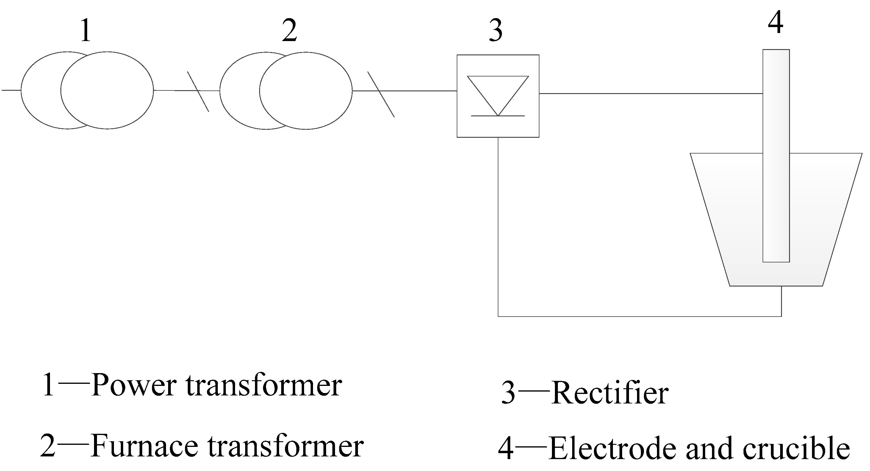
2.1.1. Selection of Power Supply

Compared with AC-EAFs (where AC is alternating-current), DC-EAFs have lower electrode consumption, more uniform temperature distribution, a simple structure, higher economic benefit, and are more suitable for metallurgical research in colleges and universities [19,20,21]. The design of the DC-EAF is shown in Figure 1. A single-electrode DC tilting furnace-type is adopted; that is, a three-phase DC power is obtained as the output after rectification. The furnace bottom is connected to one pole of the power source, and the graphite electrode on the upper side is connected to the other pole.

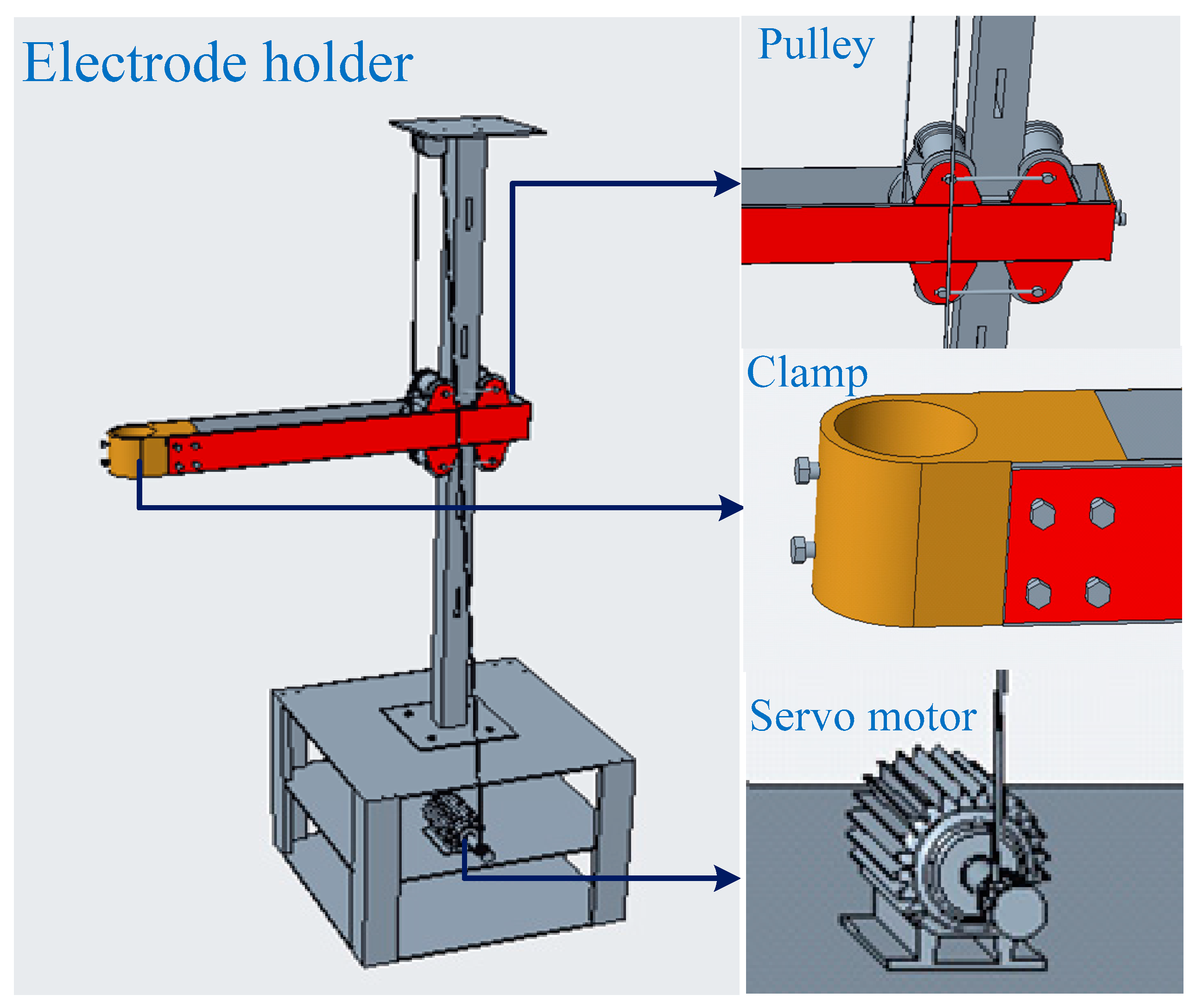
2.1.2. Electrode and Holder Design

The electrode carries the current to the molten pool. Current passing through the electrode generates heat. The size of the electrode diameter is closely related to the heat energy loss. [7,22]. The suitable diameter, for minimized heat loss, can be calculated using Equation (2).
d e l e c t r o d e = 0.406 I 2 ρ K 3
where delectrode is the diameter of the electrode (cm); I is the average electrical current (A), I = 500 A; ρ is resistivity of the electrodes, ρ = 8–13 Ω mm2·m−1; and K is a coefficient (for graphite electrodes, K = 2.1 × 10⁴ W·m−2).
The electrode holders are used to hold the electrodes and provide a pathway for current flow. Therefore, red copper material was chosen owing to its good electric conductivity. A 3D drawing of the holder is illustrated in Figure 2.

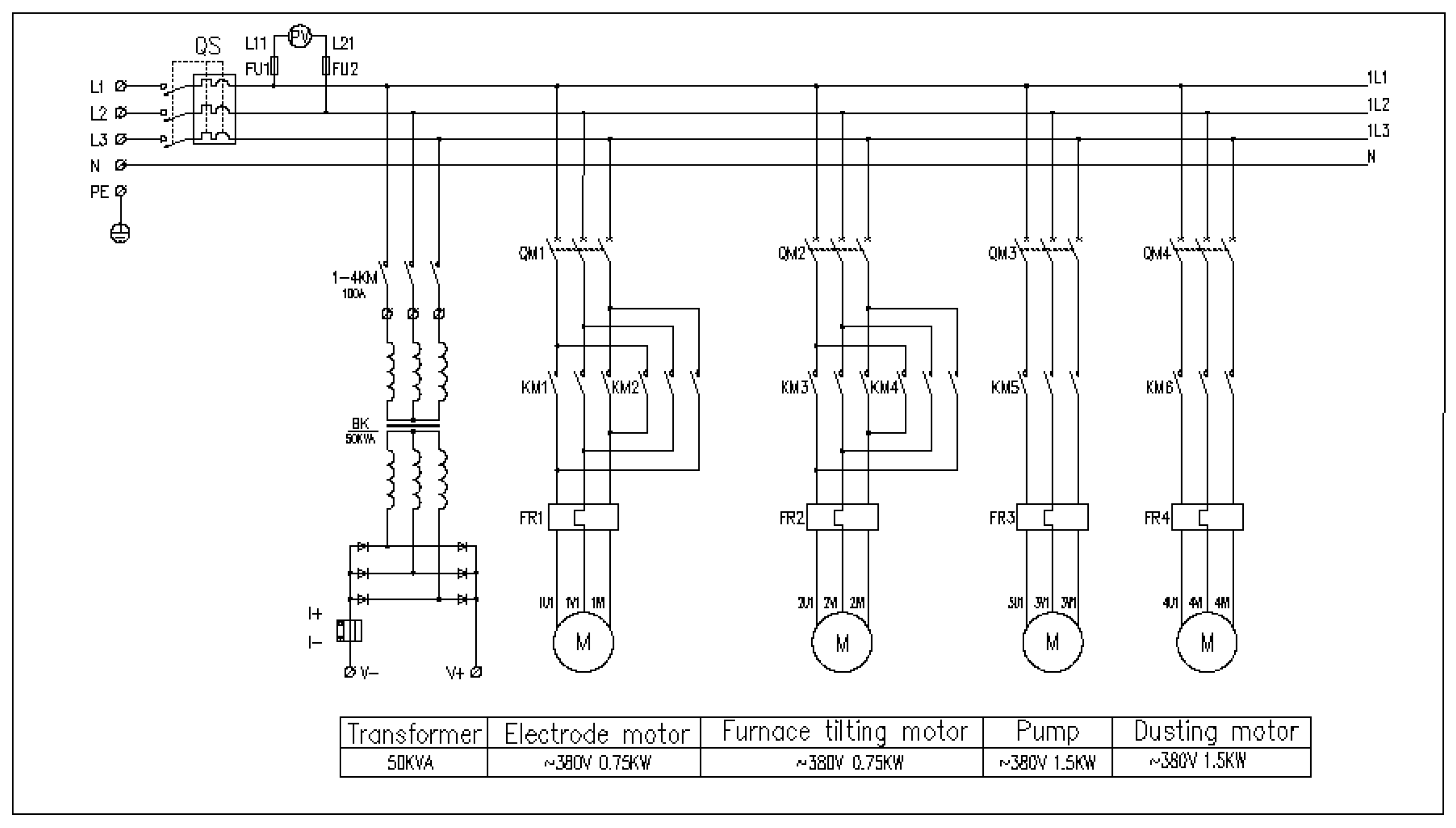
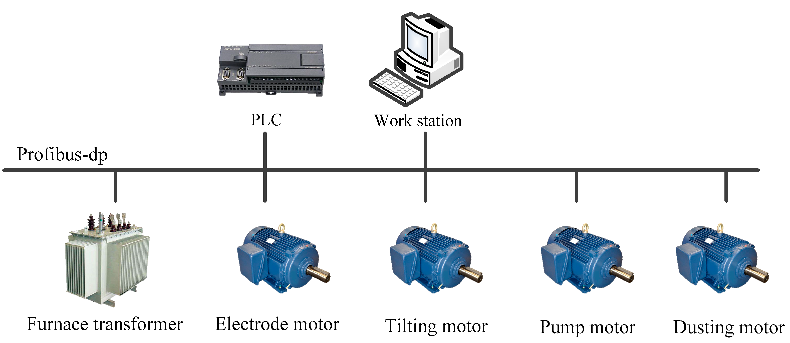
2.1.3. Electrical Control Design

The basic ideas of the electrical design are described in this section, including the relevant electrical design specifications and safe operation characteristics, by referring to the mechanical and electrical properties of the products, which are used to design the hardware of the DC-EAF [23]. This mainly includes drawing electrical schematic diagrams, wiring equipment, and writing control programs.
The PLC is an important component in the electrical design of an EAF. Thus far, PLCs have been widely used in the industrial sector [24]. Their remarkable characteristics include efficient working in harsh environments (for example, in high-temperature or high-humidity environments) and higher operating speeds than electromechanical control systems [25]. There are numerous ways to increase the arc intensity during the arc furnace melting process. In our experiment, the Siemens s7-200 PLC was used to control the motor and adjust the height of the electrode, such that the strength of the arc can be varied. Figure 3 shows a schematic diagram of the electrical control system, which helps in heat transmission, from arc to metal, and improves heat assimilation [26]. In addition, the water pump and dust motor were also controlled by the s7-200 PLC.
The PLC control must be programmed on a computer equipped with STEP 7-micro/WIN development tools [27]. The program mainly includes coded instructions to perform electrode lifting, water pump operation, and control the dust removal motor. Real-time data communication is established between the personal computer and the PLC through a TCP/IP protocol [28]. The electrical principle of the EAF, designed according to the national electrical industry design standards combined with laboratory conditions [29,30], is shown in Figure 4.

2.2. Mechanical Design

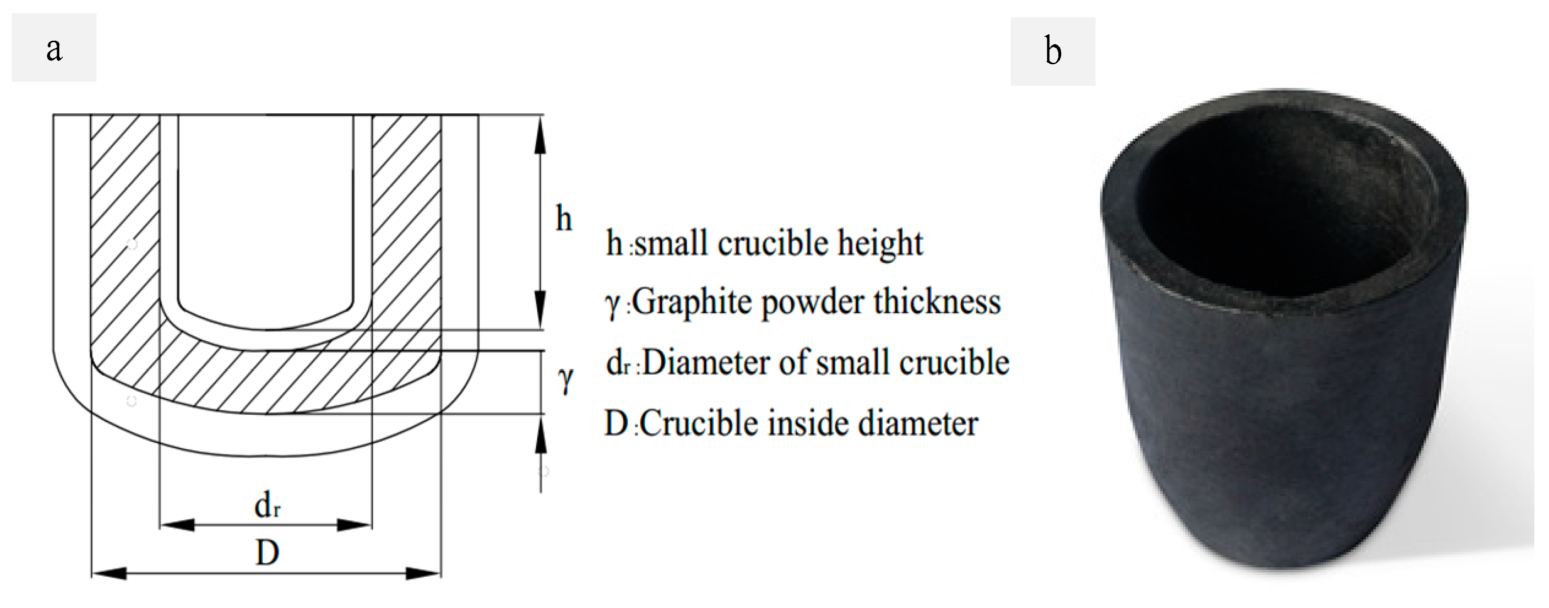
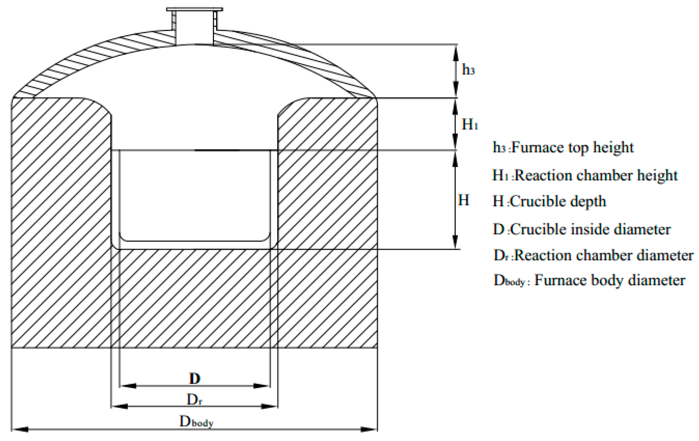
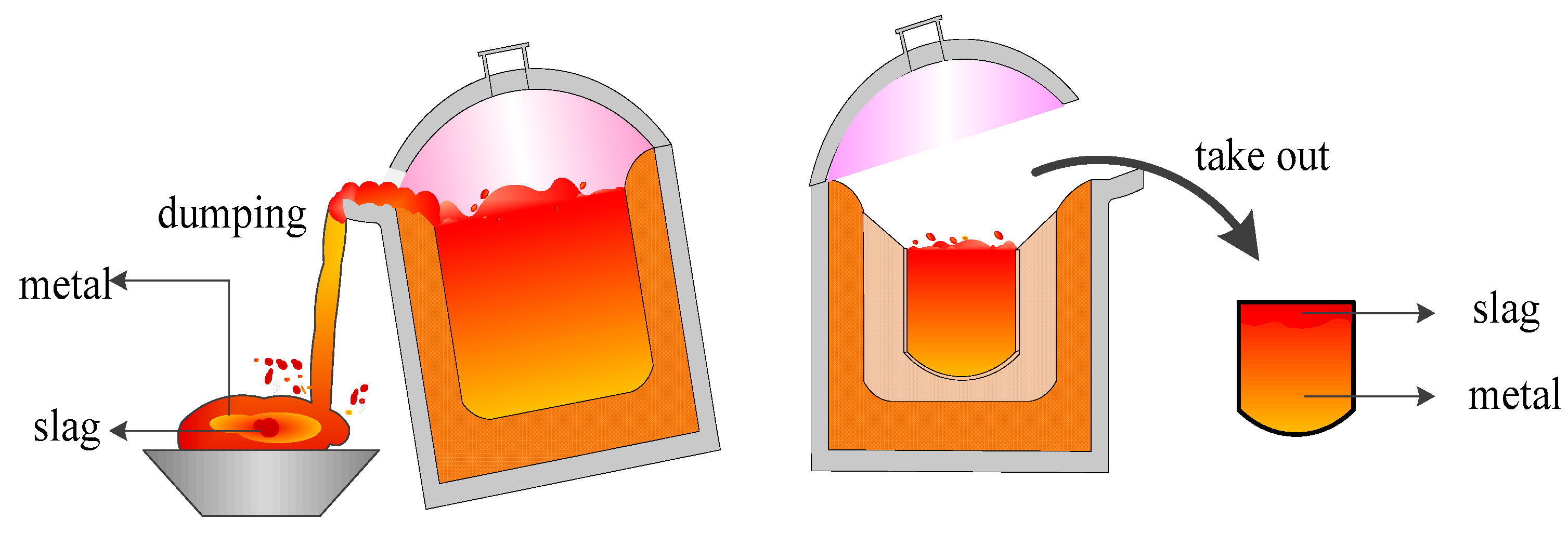
2.2.1. Crucible and Reaction Chamber Design

The shape of the EAF bath must be conducive to the smooth progress of the melting reaction. The crucible, used in this experiment, has a spherical convex top, is shown inFigure 5. This shape of the crucible enables the liquid metal to be deposited at the bottom of the bath, thereby quickly forming a molten pool, which is more convenient when tapping. Finally, graphite crucibles, which show high temperature resistance (above 2000 °C), corrosion resistance, and good electrical conductivity, are selected according to the calculated size, and based on the products available on the market, such that they do not introduce impurities in the smelting materials.
The total volume of the crucible can be calculated using Equation (3):
V = π 4 H D 2
where V is the volume, H is the height, and D is the diameter of the furnace.
The reaction chamber refers to the volume from the molten pool up to the top of the furnace (Figure 5). To prevent the liquid metal from splashing, the diameter of the reaction chamber must be larger than the bath, and is generally calculated using Equation (4):
D r = D + 2 ε
where Dr is the diameter of the melting chamber (m), and ε is the thickness of the crucible.
The height of the reaction chamber (H1) and the height of the furnace top (h3) are usually determined from the heat exchange in the furnace [18], as shown in Equations (5) and (6):
H 1 = 0.42 × D
h 3 = D r 2
While dumping the smelted products, the slag is drawn into the liquid metal, which affects the quality of the smelting products, as shown in Figure 6.
Further, with increasing smelting times, the complex environment inside the furnace accelerates the erosion (carbon consumption) of the crucible inner wall; however, frequent replacement of the crucible, due to these factors, results in high maintenance costs. Therefore, in our case, a small movable crucible was placed in a large crucible for smelting. After smelting, the product solidified, and the crucible was removed and smashed to obtain the product. This process can effectively prevent the mixing of slag and liquid metal during the dumping process and thus, crucible degradation, thereby mitigating the high maintenance costs.
Figure 7 shows the improved molten pool structure and the physical shape of the small crucible. To ensure good electrical conductivity between two crucibles, a layer of graphite powder is included between them. The surrounding environment is filled with high temperature-resistant asbestos to prevent rapid heat loss. The molten product may be removed when the melting is complete and the crucible cools in the furnace.

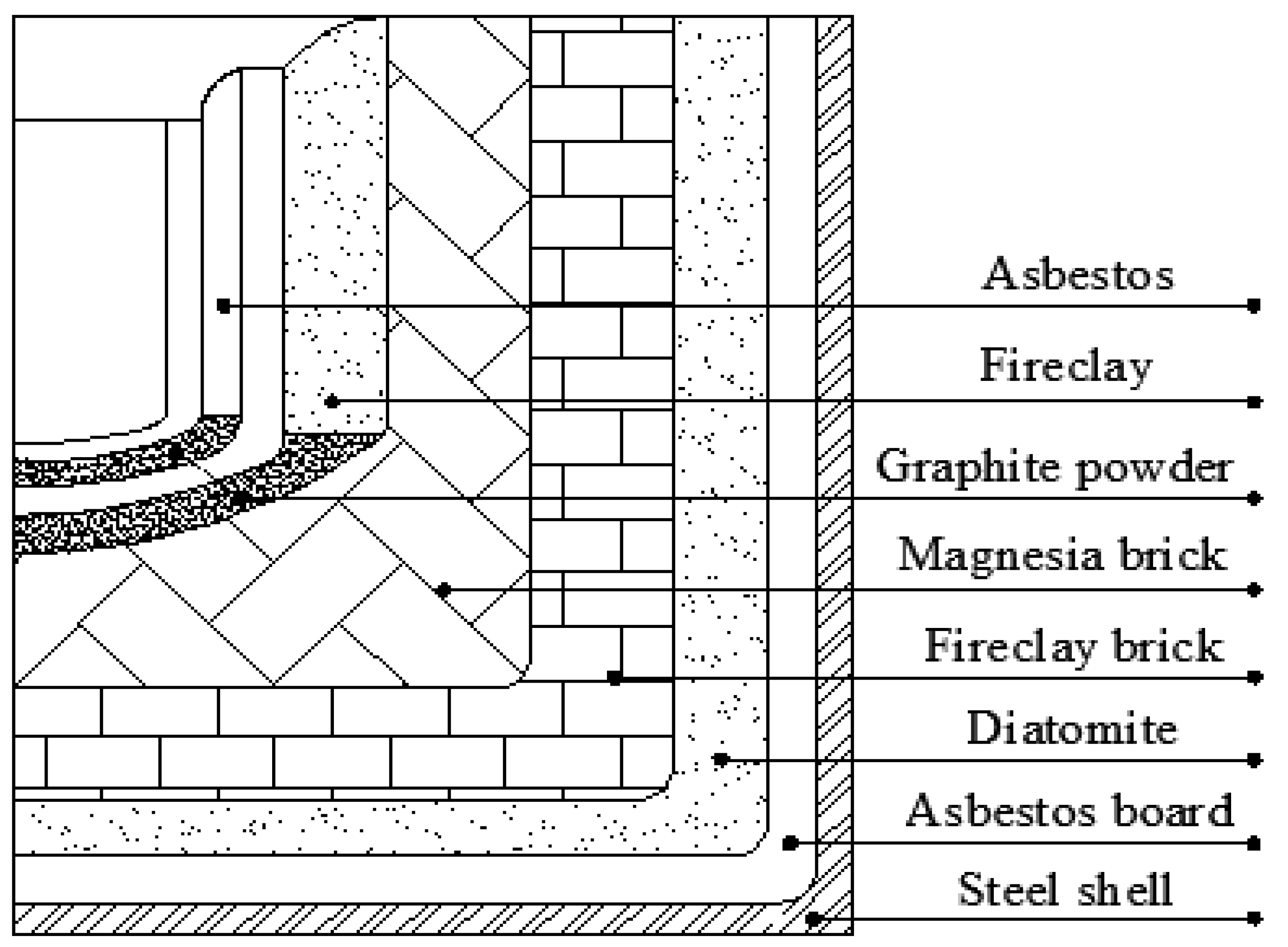
2.2.2. Furnace Lining Design

In the EAF smelting process, the lining effectively controls the heat loss and ensures uniform heating rate and maximum temperature inside the furnace; thus, the lining and bottom thickness should be rationally designed to ensure that the melting pool temperature reaches 1500–1700 °C within an hour, and the temperature of the furnace outer wall does not exceed 200 °C. To meet these conditions, the theoretical thickness of the furnace bottom and lining is calculated using the formula of a uniform flat wall and cylindrical wall [2], as shown in Equations (7) and (8) below:
E b o t t o m o = λ b δ b o t t o m ( T h T n )
E l i n i n g o = 2 π × λ l × L l n ( d 2 / d 1 ) × ( T h T n )
where E b o t t o m o is the energy loss at the bottom (W·m−2); E l i n i n g o is the energy loss from the lining (W); th is the bath temperature (°C), Th = 1923 K; tn is the outer wall temperature (°C) Tn = 473 K, δbottom is the bottom thickness (m); λb is the average thermal conductivity of the furnace bottom (W m−1 K−1); λl is the average thermal conductivity of the furnace lining (W m−1 K−1); L is the lining height of the furnace wall (m); d1 is the radius of the large crucible (m); and d2 is the radius of the furnace body (m).
The energy variation of the experimental arc furnace is nonlinear and a multistage process; however, according to the equilibrium law, the energy input of the electrode must be equal to the energy output for the entire unit and for each of its zones, as shown in Figure 8. In the figure, the arrow indicates the direction of energy transfer.
In the heating operation of the EAF, the actual power of the arc acting on the metal is only 60–65%; nearly 30% of the arc input power diffuses into the furnace, given by E d i f f u s e o , whereas approximately 10% of the energy is used in slag heating and diffusing to the furnace bottom [2,31,32,33]. Theoretically, the conduction heat, Ebottom, can be calculated as shown in Equations (9) and (10) as:
E b o t t o m o = 10 % × E e l e c i E s l a g o
E l i n i n g o = 60 % × E e l e c i + E o x i d i E m e t a l o E o t h e r o
where
  • E e l e c i 
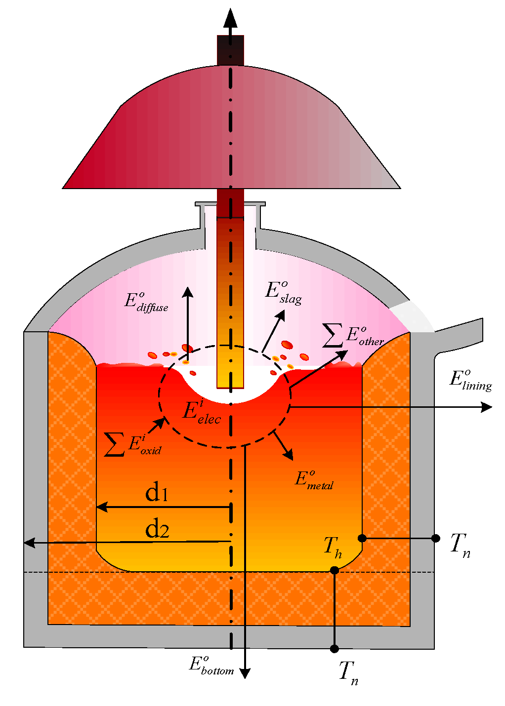
: amount of electrical energy in an DC-EAF.
  • E s l a g o : energy of slag before tapping.
  • Σ E o x i d i : chemical energy of the oxidation reactions.
  • E m e t a l o : enthalpy of liquid metal before tapping.
  • Σ E o t h e r o : other energy lost (dust, spatter, gas).
Input energy components (unit: kWh):
  • Electrical energy
The electrical energy input can be calculated based on the theoretical design of the current and voltage elements of the furnace using Equation (11):
E e l e c i = U I × t
where U is the average input voltage of the electrode (V), assuming the laboratory allowable voltage is 40 V; I is the average input current of the electrode (A), assuming the laboratory allowable current is 500 A; and t is time duration for which the furnace is operated (h), t = 90 min.
2.
Chemical energy of element reactions
After melting of titanium-containing metal pellets, titanium enters the slag in the form of oxide, and metal iron and partially reduced ferrous oxide form the metal molten pool. [2], as described by Equations (12)–(17):
[ C ] + [ O ] = { C O }
[ C ] + 2 [ O ] = { C O 2 }
C + 2 FeO = 2 Fe + CO 2
Cr 2 O 3 + 3 C = 2 Cr + 3 CO
C + 2 V 2 O 5 = 4 VO 2 + CO 2
FeTiO 3 + C = TiO 2 + Fe + CO
The heat generated from the chemical reaction mainly includes the heat generated by the elemental reaction in the bath, which can be calculated using Equation (18):
E e l e m e n t i = m ( Y i X i ) Q i o
where m is the mass of the metal inside the crucible (kg), Y i is the concentration of C, Cr, Fe, and other elements in the raw materials (%), X i is the concentration of C, Cr, Fe, and other elements in the product (%), and Q i o is the heat released (KJ/kg), by the oxidation of C, Cr, Fe, and other elements, per kilogram.
Similarly, dust oxidation also produces a small amount of energy; 77% of Fe in the dust is oxidized to FeO, and 22% of Fe is oxidized to Fe2O3 [2], which can be calculated by Equation (19):
E o t h e r i = m ( 77 % × Q F e F e O × 56 / 72 + 22 % × Q F e F e 2 O 3 × 112 / 160 ) × 1.6 %
where m is the mass of the metal inside the crucible (kg), Q F e F e O is the energy released during the oxidation of Fe into FeO (KJ/kg), Q F e F e 2 O 3 is the energy released during the oxidation of Fe into Fe2O3 (KJ/kg), and 1.6% is the proportion of dust in the total metal.
Output energy components (unit: kWh):
  • Energy of liquid metal before tapping
This part is calculated using ilmenite pellets as the raw material for EAF smelting. Before melting to form liquid metal, it must absorb some energy, which can be calculated by Equation (20):
E m e t a l o = m ( c s ( T m T r ) + c l ( T h T m ) + Q l h )
where m is the mass of the metal inside the crucible (kg), c s is the solid heat capacity of liquid metal J/(kg·K); T m is the melting point of liquid metal (K); T r is the raw material temperature, Tr = 302 K; c l is the liquid heat capacity of liquid metal J/(kg·K); T h is the temperature during tapping, Th = 1923 K; and Q l h is the latent heat of melting of ilmenite (KJ/kg).
2.
Energy of slag at tapping
This is equivalent to the enthalpy of the formation of the final slag at the tapping temperature. The total amount of slag is, on an average, equal to 6–7% of the mass of the liquid metal [2], which becomes evident from Equation (21):
E s l a g o = m ( c s l a g ( T h T r ) + Q s l a g l h ) × 6 %
where m is the mass of the metal inside the crucible (kg), T h is the temperature during tapping; Th = 1923 K; T r is the temperature of the added raw material, Tr = 302 K; Q s l a g l h is the latent heat of slag (KJ/kg); and c s l a g is the solid heat capacity of the slag J/(kg·K).
3.
Other energy losses
The energy, E s p l a s h o , lost due to splashing, about 8% of the liquid metal energies, and the energies, E i b o , E d u s t o , E g a s o , carried away by the iron beads, dust, and gas escaping through the furnace door and electrode gap, respectively, must also be considered in the calculations. The total amount of dust is, on an average, equal to 2% of the liquid metal [2]. It is assumed that the average temperature of the flue gas is 1723 K. All these parameters can be calculated by Equations (22)–(25).
E s p l a s h o = 0.8 % × E m e t a l o
E i b o = m i b ( c s i b × ( T f T r ) + c l i b × ( T h T f ) + Q i b l h )
E d u s t o = m ( ( 1450 T r ) + Q d u s t l h ) × 2 %
E g a s o = m g a s × c g a s × ( 1450 T r )
where m is the mass of the metal inside the crucible (kg), m i b is the mass of the Fe beads (kg); c s i b is the solid heat capacity of the Fe beads J/(kg·K); c l i b is the liquid heat capacity of the Fe beads J/(kg·K); T r is the temperature of the raw material, Tr = 302 K; T f is the melting point of Fe, T f = 302 K; Q i b l h is the latent heat of the Fe beads (KJ/kg); Q d u s t l h is the latent heat of dust (KJ/kg); m g a s is the mass of the gas (kg); and c g a s is the gaseous heat capacity of the furnace gas J/(kg·K).
E e l e c i + E o x i d i = E m e t a l o + E s l a g o + E o t h e r o + E b o t t o m o + E d i f f u s e o + E l i n i n g o
The energy balance formula is shown in Equation (26), and the energy balance, calculated based on the data and the above-mentioned equations, is shown in Table 2.
Based on the calculated lining thickness, an appropriate refractory material is selected according to the actual insulation effect. The lining material of an electric furnace should be highly fire resistant and have good thermal stability and low thermal conductivity. It is more economical to select high-quality refractories and use thinner linings to ensure that heat loss is not reduced [34]. The lining mainly consists of a thermal insulation layer, protective layer, and working layer. The parameters of the commonly used refractory materials are listed in Table 3 [35].
The insulation layer of the furnace lining was made of asbestos board, and the thickness was approximately 10 mm. The upper asbestos board was covered with a layer of diatomaceous earth, with a thickness ranging from 5 to 20 mm. Another layer of clay bricks was built at the bottom and side-wall of the furnace, and the cracks were filled with clay powder and compacted. A conductive plate was placed on top of the firebricks at the bottom, surrounded by clay powder, and a rectangular graphite plate, dusted with graphite powder, was laid on top. The furnace walls were lined with magnesia bricks and filled with clay powder. The roof of the furnace was casted with a refractory material. The furnace lining structure is shown in Figure 9.
Thus, the diameter of the furnace body can be calculated by considering all the above-mentioned refractory material layers as:
D b o d y = D + 2 δ + 2 ε + 2 β
where D b o d y is the diameter of the furnace body (m), D is the inner diameter of the crucible, δ is the thickness of the lining, ε is the thickness of the crucible, and β is the thickness of the steel shell (6 to 32 mm).

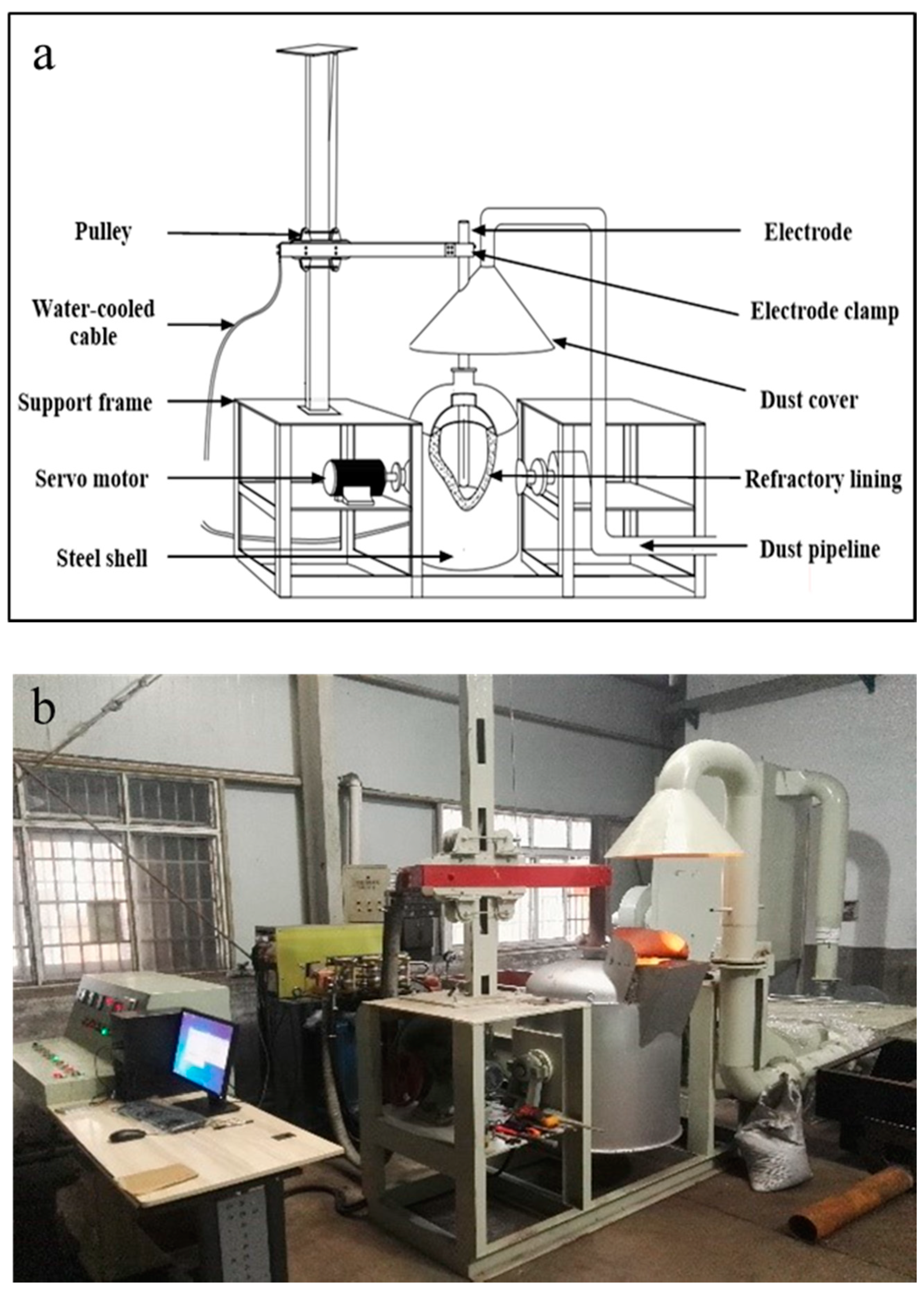
2.3. Overall Design of the Electric Furnace

The DC-EAF system consists of transformers, rectifiers, EAFs, control cabinets, coolers, cyclones, etc. According to the actual situation, we chose a three-phase oil-immersed transformer, with a bridge rectifier, to obtain the direct current required by the EAF. The main parameters of the EAF transformer are listed in Table 4.
The lining and bottom thicknesses and other dimensions of the furnace are shown in Table 5.
The transformer and the electrode are connected by two flexible water-cooled cables, which allow the electrodes to move vertically and swing with the furnace body. The dust removal equipment was designed according to the size of the DC-EAF. The furnace is shown schematically in Figure 10.
The designed DC-EAF can be used to smelt metal and slag. This DC-EAF enables rapid melting with good heat preservation; however, some limitations have been observed in the designed DC-EAF-induced smelting, namely, the electrical parameters of the electrode cannot be controlled easily, which leads to arc breaking, excessive electrode consumption, long smelting time, high power consumption, and high cost of single furnace smelting.

3. Data Collection and Applications

As an effective approach to solve the problem of excessive power consumption, we designed a real-time process monitoring system by analyzing the relationship between the current and the arc, based on the DC arc model. This system collects information pertaining to the electrical parameters (electrode voltage, electrode current, etc.) in real time via PLC, which guides the operation of power supply in the experiment and collects feedback in real time. The monitoring system is driven by the information flow to realize closed-loop control of the smelting process effectively.

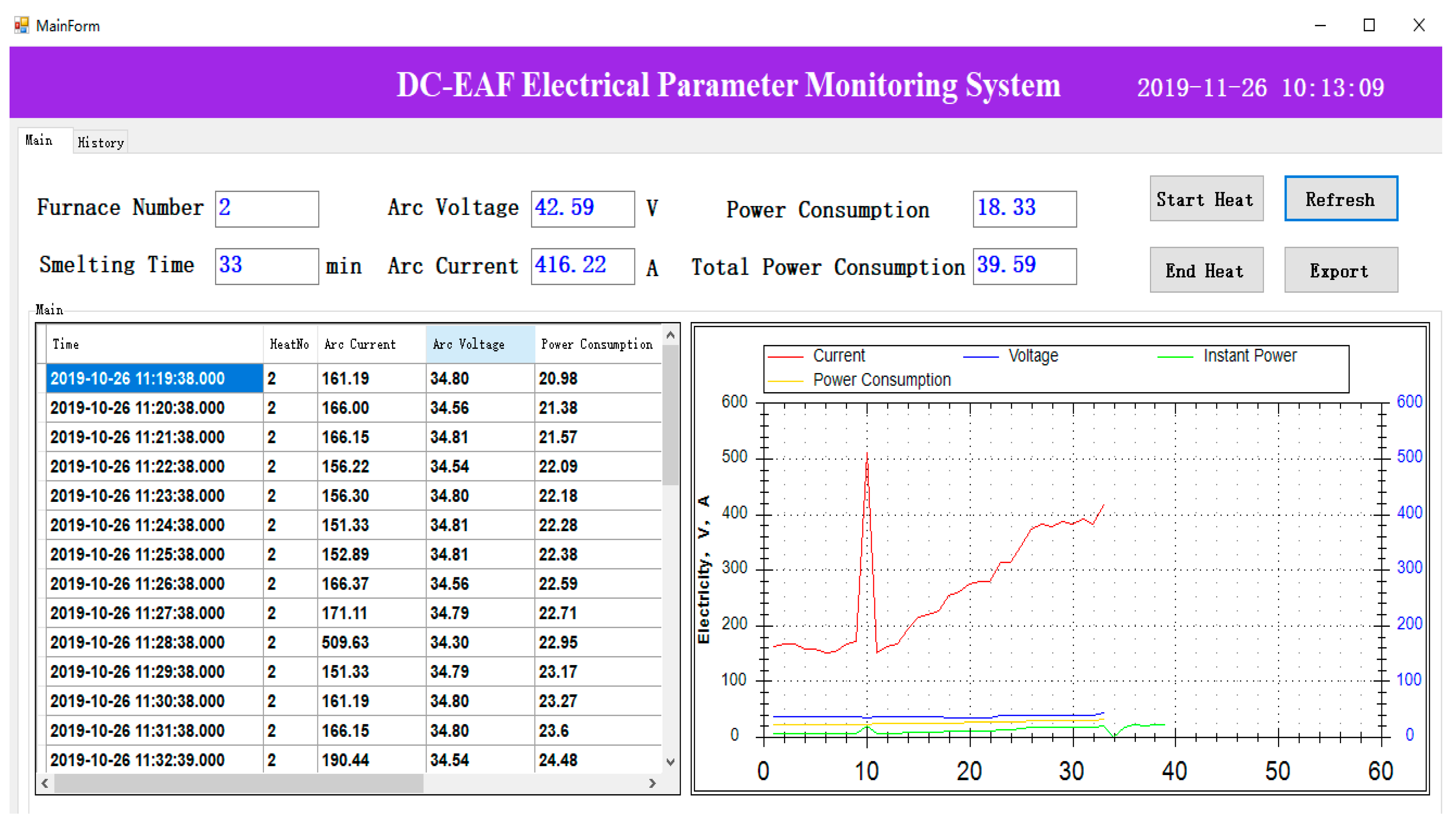
3.1. Data Collection

During the EAF smelting process, the arc length has a significant effect on the heat transfer efficiency of the liquid metal [36]. The arc length is different during each smelting period. To ensure the effective utilization of arc energy, changes in the electrode voltage and current must be monitored, and the electrode rise and fall must be adjusted reasonably, as directed by Equation (28):
l = K T × I 2 9.8 μ × S + H
where l is the arc length (m); H is the distance from the bottom of the electrode to the liquid metal level (m); KT is the correction coefficient (N/kA2); I is the arc current (kA); μ is the density of liquid metal; and S is the area of arc impact (m2).
The electrical parameters of each stage of the smelting process are collected and stored in the SQL2008 database for subsequent processing and analysis.

3.2. Software Development

To shorten the data acquisition time, while simultaneously ensuring collection accuracy, KEPServerEX software was used to configure the data collection environment. The software is widely used, owing to its simple operation and fast data processing speed.
The software was developed using Visual Studio.NET 2010 software by C# language. The graphical user interface (GUI) of this system is shown in Figure 11.

4. Results and Discussion

To evaluate the operation and performance of the designed DC-EAF, titanium-containing metallized pellets were used for melting test verification. The content of Cr2O3, V2O5 and other impurities in titanium-containing metallized pellets was high. Adding reducing agent during the melting process can result in some impurities to reduce and enter the molten iron, thus reducing the impurity content in high-titanium slag, improving the alloy elements in molten iron, and realizing the separation of high-titanium slag and iron. The raw materials were detected by X-ray fluorescence spectroscopy (XRF), the composition of the metallized pellets and coke is shown in Table 6 and Table 7.
Titanium-containing metallized pellets were crushed to 10–15 mm by the counter-roller crusher. To find the optimal concentration of the reducing agent, four groups of experiments were conducted with coke concentrations (wt.%) of 0, 1, 4, and 6% coke, respectively. It was estimated that the experimental temperature of each group reached 1600 °C and the melting time was 90 min. Figure 12 illustrates the physical schematics of the reduced samples and crucibles in the four groups of experiments. The cross-section of the crucible reflects the clear boundary between metal and slag, which effectively prevents secondary pollution between the metal and slag.
The reduced slag sample was ground into powder, and visible metallic iron particles were screened out. Then iron was separated from titanium slag by a wet magnetic method. The titanium slag before and after wet magnetic separation was analyzed by chemical element titration. The results are shown in Table 8.
Table 8 shows that without coke, the TiO2 content in slag was 59.44%, and the Cr2O3 content in slag was 1.29%. When the coke with a total weight of 1% was added, the TiO2 content in the slag was 65.45%, and the Cr2O3 content in the slag was 0.56%. When coke with a total weight of 4% was added, TiO2 in slag was 93.34%, and Cr2O3 in slag was 0.31%. When coke with a total weight of 6% was added, the TiO2 content in the slag was 86.83%, and the Cr2O3 content in the slag was 0.25%. These results demonstrate that coke with a total weight of 4% was the effective condition for facilitating the enrichment effect of TiO2 in high-titanium slag, with TiO2 in slag reaching 93.34%. This test verifies the applicability of the designed DC electric arc furnace, highlighting its potential applicability in industry.
In future studies, the influence of the distance between electrodes and the molten steel on the EAF performance must be investigated to improve the monitoring system and extend its applications.

5. Conclusions

Herein, the development of EAF over the years was reviewed and analyzed, whereby it was demonstrated that the existing EAFs should be improved via mitigation of their drawbacks (incomplete separation of metal and slag and poor thermal insulation effect) and redesigned through experimentation in universities and research institutes. Based on these points, in this study, we developed a DC-EAF that was capable of fast heating and producing a good separation effect between the metal and slag. The main conclusions of our study are as follows:
  • The mechanical structure was designed, which included the power supply mode, electrode and electrode holder, electric circuit, crucible, and the reaction chamber structure. The embedded design of the crucible was used to separate the metal and the slag. In addition, the surface lining and bottom thicknesses were determined using the heat balance equations.
  • The EAF smelting efficiency factors were analyzed. The voltage, current, smelting time, and temperature data of the experimental electrode were collected by PLC, and the electric parameter monitoring system of the DC-EAF was developed.
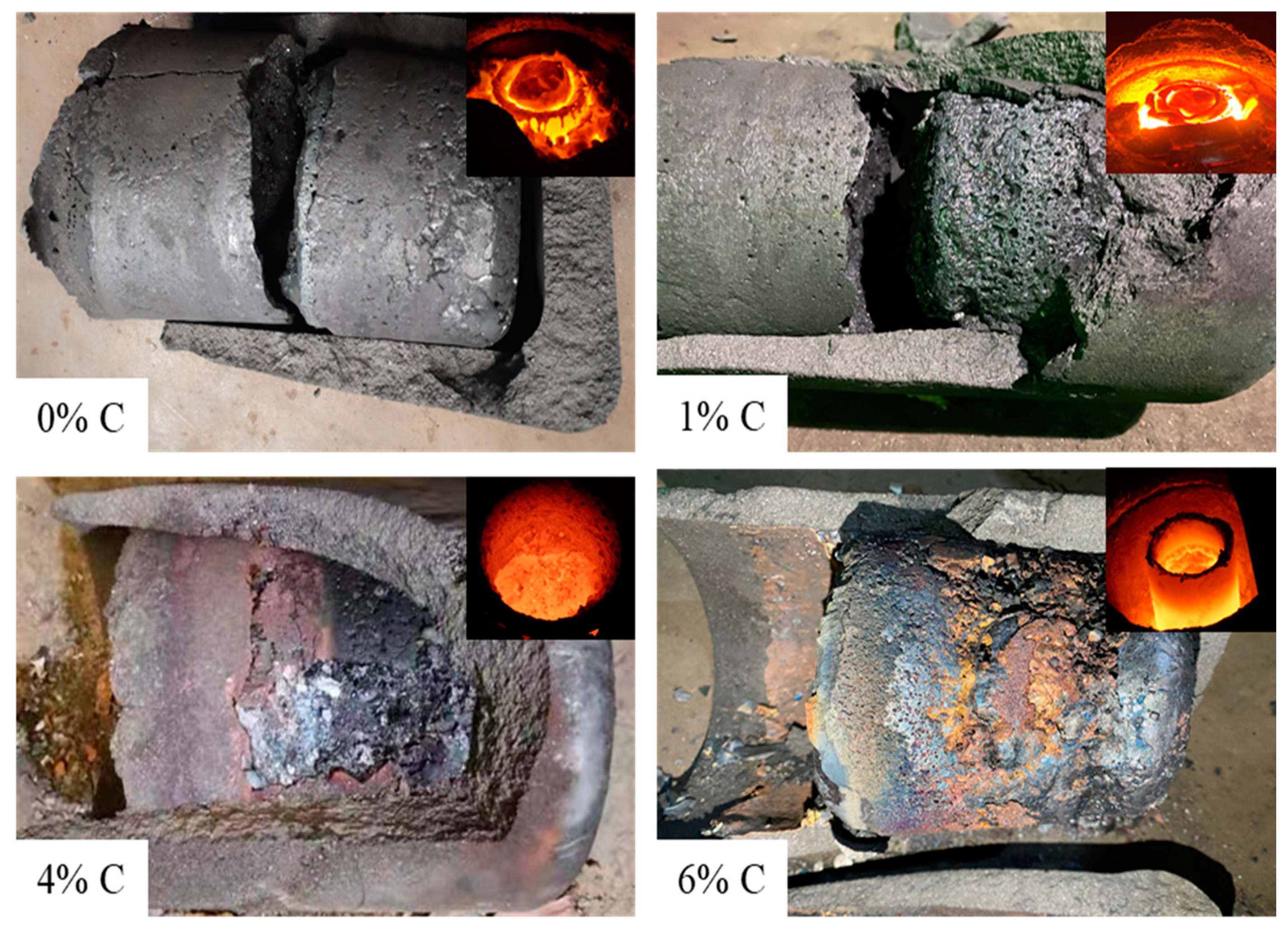
  • In the performance evaluation test of the arc furnace, the optimal weight percentage of the reducing agent was investigated. The results show that for separating 12 kg of titanium-containing metallized pellets when the temperature (1607 °C) and smelting time (90 min) were constant, coke with a total weight of 4% coke was the most effective condition for facilitating the enrichment effect of TiO2 in high-titanium slag; consequently, the TiO2 content in slag reached 93.34%. This shows that the proposed DC-EAF meets the design requirements of lining thickness and achieves a good metal-slag separation.

Author Contributions

B.X., L.Y. contributed to the conception of the study; B.X. performed the experiment; S.W., F.Z. contributed significantly to analysis and manuscript preparation; B.X., Z.Y. performed the data analyses and wrote the manuscript; Y.G., F.C., L.Y. helped perform the analysis with constructive discussions. All authors have read and agreed to the published version of the manuscript.

Funding

This research was funded by the National Natural Science Foundation of China (No. 51804345) and the Fundamental Research Funds for the Central Universities of Central South University (No. 2020zzts747).

Informed Consent Statement

Not applicable.

Data Availability Statement

Restrictions apply to the availability of these data. Data was obtained from Central South University and are available from the Botao Xue with the permission of Central South University.

Conflicts of Interest

The authors declare no conflict of interest.

References

  1. Madias, J. Treatise on Process Metallurgy; Seetharaman, S., Ed.; Elsevier: Boston, MA, USA, 2014; pp. 271–300. [Google Scholar]
  2. Toulouevski, Y.N.; Zinurov, I.Y. Innovation in Electric Arc Furnaces Ⅱ: Scientific Basis for Selection; Toulouevski, Y.N., Zinurov, I.Y., Eds.; Springer: Berlin/Heidelberg, Germany, 2013; pp. 1–24. [Google Scholar]
  3. Ministry of Industry and Information Technology of the People’s Republic of China. The Ministry of Industry and Information Technology Issued a Notice on the Steel. Industry Adjustment and Upgrading Plan (2016–2020). Available online: https://www.miit.gov.cn/zwgk/zcwj/wjfb/zh/art/2020/art_4ec2537d42b947e3bbac6a70babbaa05.html (accessed on 14 November 2016).
  4. Lupi, S. Fundamentals of Electroheat: Electrical Technologies for Process Heating; Lupi, S., Ed.; Springer International Publishing: Cham, Switzerland, 2017; pp. 83–205. [Google Scholar]
  5. Xu, X. Overview of the development of DC arc furnaces at home and abroad. Hum. Metall 1996, 2, 57–60. [Google Scholar]
  6. Yu, M.Q. Overview of the development of DC arc furnace technology at home and abroad. Shanghai Metall Inf. 1998, 4, 1–10. [Google Scholar]
  7. Oyawale, F.A.; Olawale, D.O. Design and prototype development of a mini-electric arc furnace. Pac. J. Sci. Technol. 2007, 8, 12–16. [Google Scholar]
  8. Yin, J.F. Experimental study on process granulated water quenching slag by dc electric arc furnace. Min. Metall 2011, 20, 82–85. [Google Scholar]
  9. Barbouche, M.; Hajji, M.; Ezzaouia, H. Electric arc furnace design and construction for metallurgical and semiconductor research. Int. J. Adv. Manuf. Technol. 2016, 82, 997–1006. [Google Scholar] [CrossRef]
  10. Sun, D.C.; Sun, Y.C. Current Situation and Development of DC Arc Furnace at Home and Abroad. In Proceedings of the 9th Academic Conference on Carbon Materials, Chinese Society of Metals, Shanghai, China, 1 April 1994. [Google Scholar]
  11. Schub, M.; Xiao, B. Economical and energy-saving unarc DC arc furnace. Energy Metall Ind. 1993, 12, 57–60. [Google Scholar]
  12. Gu, H.X. Direct current electric arc furnace. Spec. Steel. 1983, 4, 88–90. [Google Scholar]
  13. Zhang, H.S. Reconstruction of 5—ton arc furnace. Heavy Mach. 1989, 4, 47–48. [Google Scholar]
  14. Wang, J.Z.; Liu, X.W. Research and development of DC arc furnace in Chengdu Seamless Steel. Tube Company. Spec. Steel. Technol. 1995, 1, 23–24. [Google Scholar]
  15. Liu, X.R. Design and Operation of 10t Single Electrode DC Arc Furnace. Ind. Heat 1995, 2, 33–35. [Google Scholar]
  16. Sui, L.L. Theory and Technology of Green Utilization of Titanium Slag; Northeastern University: Boston, MA, USA, 2015. [Google Scholar]
  17. Ma, X.; Han, F.X.; Lei, T. Factor of reductant carbon during titanium slag smelting in closed direct current arc furnace. J. Kunming Univ. Technol. 2013, 38, 6–10. [Google Scholar]
  18. Edneral, F.P. Electrometallurgy of Steel and Ferro-Alloys; MIR Publishers: Moscow, Russia, 1979; pp. 1–87. [Google Scholar]
  19. Bowman, B. Performance Comparison Update-Ac vs Dc Furnaces. Iron Steel. Eng. 1995, 72, 26–29. [Google Scholar]
  20. Saevarsdottir, G. Handbook of Ferroalloys; Gasik, M., Ed.; Butterworth-Heinemann: Oxford, UK, 2013; pp. 139–175. [Google Scholar]
  21. Zheng, J.H. Comparison and technology analysis of UHP electrode performance in AC and DC electric arc furnaces. Carbon Tech. 2002, 4, 28–32. [Google Scholar]
  22. Yan, L.Y.; Wu, Z.T.; Rui, S.S. Design and application of the bottom electrode of DC arc furnace. Metall. Equip. 1995, 05, 16–18. [Google Scholar]
  23. Mullinger, P.; Jenkins, B. Industrial and Process. Furnaces, 2nd ed.; Mullinger, P., Jenkins, B., Eds.; Butterworth-Heinemann: Oxford, UK, 2013; pp. 289–335. [Google Scholar]
  24. Dednev, A.A.; Elizariov, K.A.; Kissel’man, M.A.; Nekhamin, S.M. Control systems of melting electric furnaces in metallurgy and mechanical engineering. Russ. Metall 2013, 6, 442–449. [Google Scholar] [CrossRef]
  25. Shinya, O. Programmable Logic Controller. Progr Log. Control. 2012, 62, 1–22. [Google Scholar]
  26. Skripchenko, S.V.; Nikol’skii, L.E.; Pis’mennyi, V.A. Study of the efficiency of use of electric power in the production of steel in an arc furnace. Metall 1988, 32, 150–151. [Google Scholar] [CrossRef]
  27. Siemens. S7-200 Programming Manual. Available online: https://cache.industry.siemens.com/dl/files/582/1109582/att_22063/v1/s7200_system_manual_en-US.pdf (accessed on 10 February 2021).
  28. Postel, J. DOD standard transmission control protocol. ACM SIGCOMM Comput. Commun. Rev. 1980, 10, 52–132. [Google Scholar] [CrossRef]
  29. IEEE. National Electrical Safety Code (NESC) Handbook, 7th ed.; IEEE: Piscataway Township, NJ, USA, 2011; pp. 1–802. [Google Scholar]
  30. Allen, L. Clapp. Installation and Maintenance of Equipment. In NESC Handbook: A Discussion of the National Electrical Safety Code; IEEE: Piscataway Township, NJ, USA, 2011; pp. 148–176. [Google Scholar]
  31. Persson, J.A.; Andrews, R.E.; Maola, M. Arc Furnace Electrode Control. US US4620308 A, 28 October 1986. Available online: https://www.freepatentsonline.com/4620308.pdf (accessed on 10 February 2021).
  32. Dong, Q.; Zhang, J. Simulation of superfluid and heat transfer in plasma arc region of AC electric arc furnace. In CFD Modeling and Simulation in Materials Processing; Nastac, L., Zhang, L., Thomas, B.G., Zhu, M., Ludwig, A., Sabau, A.S., Pericleous, K., Combeau, H., Eds.; John Wiley & Sons, Inc.: Hoboken, NJ, USA, 2016; pp. 35–42. [Google Scholar]
  33. Reynolds, Q.G.; Jones, R.T.; Reddy, B.D. Mathematical and computational modelling of the dynamic behaviour of direct current plasma arcs. J. S. Afr. Inst. Min. Metall. 2010, 110, 733–742. [Google Scholar]
  34. Biswas, S.; Sarkar, D. Introduction to Refractories for Iron- and Steelmaking; Biswas, S., Sarkar, D., Eds.; Springer International Publishing: Cham, Switzerland, 2020; pp. 249–267. [Google Scholar]
  35. Song, X.W. Technology of Refractory Materials; Beijing Chemical Industry Press: Beijing, China, 2008; pp. 63–105. [Google Scholar]
  36. Kazak, O. Modeling of vortex flows in direct current (DC) electric arc furnace with different bottom electrode positions. Metall Mater. Trans. B 2013, 44, 1243–1245. [Google Scholar] [CrossRef]
Figure 1. Schematic diagram of the electric arc furnace system structure.
Metals 11 00732 g001
Figure 2. 3D schematic diagram of the electrode holder.
Metals 11 00732 g002
Figure 3. Schematic diagram of the electrical control system.
Metals 11 00732 g003
Figure 4. Schematic diagram of part of the system hardware circuit.
Metals 11 00732 g004
Figure 5. Schematic diagram of the arc furnace with dimensions.
Metals 11 00732 g005
Figure 6. Comparison of metal and slag separation effects.
Metals 11 00732 g006
Figure 7. (a) Schematic diagram and (b) image of the improved crucible and molten pool structure.
Metals 11 00732 g007
Figure 8. Schematic diagram illustrating heat exchange inside the furnace.
Metals 11 00732 g008
Figure 9. Illustration of the furnace lining with refractory materials.
Metals 11 00732 g009
Figure 10. (a) Schematic diagram and (b) image of the electric arc furnace.
Metals 11 00732 g010
Figure 11. GUI for the process monitoring system.
Metals 11 00732 g011
Figure 12. Physical schematic of the reduced samples and crucible.
Metals 11 00732 g012
Table 1. Comparison of the tapping methods in Previous Studies.
CompanyYearCapacityNoteReferences
ABB19727 t\Sun et al. [10]
IRSID19796 t\Xu [5]
MAN-GHH198212 tBottom tappingSchub., M et al. [11]
SMS198312 tTilting tappingGu [12]
MAN-GHH19850.5 t\Xu [5]
Taiyuan Heavy Machinery 19895 tTilting tappingZhang [13]
Chengdu Seamless Steel Tube19915 tTilting tappingWang et al. [14]
Shanghai Fifth Steel Works199510 tEBTLiu [15]
\20072 kgTilting tappingFestus et al. [7]
\2011250 kgTilting tappingYin et al. [8]
\2015\\Barbouche et al. [9]
Table 2. Energy balance of DC-EAF.
Input Energy kWh (10 kg)−1%
1. Electric energy E e l e c i 1596.22
2. Chemical energy of oxidation reactions E o x i d i 0.593.78
energy of element oxidation E e l e m e n t i 0.442.82
other small energy sources E o t h e r i 0.150.96
--Ʃ 15.59100
Output energy kWh (10 kg)−1%
1. Energy of liquid metal before tapping E m e t a l o 3.8224.50
2. Energy of slag before tapping E s l a g o 0.221.41
3. Other energy losses E o t h e r o 0.140.90
energy of the splash E s p l a s h o 0.030.19
energy carried away by the iron beads E i b o 0.010.07
energy carried away by the dust E d u s t o 0.070.45
energy taken away by the gas E g a s o 0.030.19
4. Energy diffused at the bottom E b o t t o m o 1.288.21
5. Energy diffused in the furnace E d i f f u s e o 4.528.87
6. Loss of energy from furnace walls E l i n i n g o 5.6336.11
--Ʃ 15.59100
Table 3. Main parameters of the refractory materials.
MaterialsTemperature
T/°C
Density
ρ/(kg m−3)
Thermal Conductivity
λ/(W m−1 °C−1)
Asbestos board600–70080–1400.10–0.26
Diatomite900440–5000.0395 + 0.00019 T
Fireclay 1100–1300800–1300[0.29–0.41] + 0.00026 T
Fireclay brick1350–14501800–2040[0.7–0.84] + 0.00058 T
Magnesia brick600–17002300–26002.1 + 0.00019 T
Table 4. Main parameters of the furnace transformer.
ItemsParametersItemsParameters
Connection ModeTriangle/StarRectifier ModeBridge Rectifier
Input voltage380 VDirect voltage output35/40/45/50 V
Input current75 ADirect current output≤1250 A
Table 5. Furnace structure parameters and corresponding dimensions.
ItemsParametersItemsParameters
Electrode Diameter40 mmStroke of Electrode1000 mm
Reaction chamber height (H1)90 mmSmall crucible thickness20 mm
Small crucible diameter (dr)165 mmLarge crucible thickness25 mm
Large crucible diameter (Dr)255 mmSmall crucible height (h)50 mm
Furnace top height (h3)130 mmLarge crucible height (H)70 mm
Furnace bottom thickness330 mmFurnace lining thickness 265 mm
Furnace body height750 mmFurnace body diameter800 mm
Table 6. Composition of high-titanium metal pellets (wt.%).
CompositionFeCaOSiO2MgOAl2O3K2ONa2OCr2O3TiO2V2O5
Content65.660.392.190.641.590.0730.170.5826.100.41
Table 7. Coke composition (wt.%).
CompositionCOAlSiSFeCaMgTiCr
Content89.105.451.671.641.120.320.230.160.05<0.01
Table 8. Composition of coke samples (wt.%).
NO.Pellet Weight
(kg)
Coke Weight
(kg)
Time
(min)
Temperature
(°C)
Content in Slag after Smelting
FeO
(%)
TiO2
(%)
Cr2O3
(%)
V2O5
(%)
16090184119.3559.441.291.14
2120.1290162014.5465.450.561.57
3120.489016073.0493.340.310.47
4120.7290159411.8886.830.250.30
Publisher’s Note: MDPI stays neutral with regard to jurisdictional claims in published maps and institutional affiliations.

