Abstract
This study aimed to identify an optimal heat-treatment parameter set for an additively manufactured AlSi10Mg alloy in terms of increasing the hardness and eliminating the anisotropic microstructural characteristics of the alloy in as-built condition. Furthermore, the influence of these optimized parameters on the fatigue properties of the alloy was investigated. In this respect, microstructural characteristics of an AlSi10Mg alloy manufactured by laser-based powder bed fusion in non-heat-treated and heat-treated conditions were investigated. Their static and dynamic mechanical properties were evaluated, and fatigue behavior was explained by a detailed examination of fracture surfaces. The majority of the microstructure in the non-heat-treated condition was composed of columnar grains oriented parallel to the build direction. Further analysis revealed a high fraction of pro-eutectic α-Al. Through heat treatment, the alloy was successfully brought to its peak-hardened condition, while eliminating the anisotropic microstructural features. Yield strength and ductility increased simultaneously after heat treatment, which is due to the relief of residual stresses, preservation of refined grains, and introduction of precipitation strengthening. The fatigue strength, calculated at 107 cycles, improved as well after heat treatment, and finally, detailed fractography revealed that a more ductile fracture mechanism occurred in the heat-treated condition compared to the non-heat-treated condition.
1. Introduction
Laser-based powder bed fusion of metals (PBF-LB/M), also known as selective laser melting (SLM), as one of the highly promising additive manufacturing (AM) processes to produce light metal parts, is a feasible complement to conventional fabrication methods in various industries. PBF-LB/M enables the generation of parts by selectively scanning thin layers of powder metals with a laser beam based on a three-dimensional computer-aided design (CAD) model [1,2]. Like other AM technologies, PBF-LB/M allows the production of individualized and geometrically complex shapes [3].
One of the commonly used alloys in PBF-LB/M processes is AlSi10Mg. This alloy offers a relatively high fluidity, low shrinkage, and a reduced solidification temperature range, which results in better casting properties [4]. It is also classified within the age-hardenable alloys, as the addition of Mg enables the precipitation of nanoscale Mg2Si particles and thus strengthens the alloy [5]. To achieve the desired mechanical properties, heat treatment is usually applied to reach a peak-hardened condition.
The excellent combination of low weight, high heat conductivity, and good mechanical properties has led to this alloy being used in many different applications such as in the aerospace and automotive industries [6,7]. However, due to reliability concerns associated with the components produced using PBF-LB/M, their application is currently limited. One of the most important properties to be considered when evaluating materials for industrial applications is their fatigue behavior.
There exist a number of studies on the fatigue behavior of PBF-LB/M-fabricated AlSi10Mg alloys. Aboulkhair et al. [8] investigated the influence of T6 heat-treatment with conventional treatment parameters as well as machining on the fatigue properties of AlSi10Mg alloys, reporting desirable fatigue properties for specimens subjected to both T6 heat-treatment and surface machining. Mfusi et al. [9] revealed that the alloy exhibits better fatigue strength after stress relief, though all other mechanical properties obtained by the fabrication process deteriorate. Beretta et al. [10] explored the effect of surface roughness as a result of build orientation on fatigue crack growth, demonstrating that there is a moderate correlation between surface roughness parameters and surface features measured by area, and they constructed a model to describe fatigue strength. Tang et al. [11] demonstrated the possibility of using extreme-value statistics to predict the fatigue life of additively manufactured as-built and heat-treated AlSi10Mg parts, with inputs of pore size distribution measured on a polished plane. Zhang et al. [12] looked at the effect of heat treatment on the microstructure and fatigue life of PBF-LB/M-manufactured AlSi10Mg. In another study, Bhaduri et al. [13] investigated the mechanical properties, heat treatment, and microstructural characteristics of a hybrid specimen fabricated by additive manufacturing of AlSi10Mg on top of a conventionally fabricated AA6082 alloy. They showed that the heat treatment affects the failure location, providing a path to fabricate larger parts without loss of strength. In all these cases, different process parameters, e.g., laser power, scanning speed, slicing thickness, and the machine itself, were utilized to additively fabricate the samples. Furthermore, the post-heat-treatment parameters, e.g., heat-treatment methods, timing, and temperatures, varied from case to case as well. Since the modifications in microstructural characteristics and hence mechanical properties after heat treatment depend on the initial microstructure of an alloy, i.e., as-built, it is important to investigate the heat-treatment parameters and their intrinsic influences on a given alloy with a specific microstructure and further extend these investigations into the resulting mechanical properties.
The present study was firstly aimed at finding optimum heat-treatment parameters for our fabricated alloy in terms of increasing the hardness and eliminating the anisotropic microstructural properties of the manufactured parts. Furthermore, the influence of heat treatment on the fatigue properties was investigated, and finally, fracture surface analyses of the alloy were carried out.
2. Materials and Methods
2.1. PBF-LB/M Fabrication and Material
Since the main objective of this work was to investigate the influence of heat treatment on microstructural characteristics and fatigue behavior of the AlSi10Mg alloy, the processing conditions and chemical composition were kept identical. The processing conditions, e.g., laser power, scanning speed, beam diameter, hatch space, slice thickness, and scanning strategy. are listed in Table 1. The chess pattern with a field size of 5.89 mm × 5.89 mm was displaced in each layer by 4.02 mm in X and 5.44 mm in Y direction to suppress the microstructural anisotropy that could otherwise arise from a unidirectional scanning strategy. To fabricate the materials, a TruPrint 3000 machine (TRUMPF GmbH + Co. KG, Ditzingen, BW, Germany) was utilized. The machine is equipped with a cylindrical build-chamber of Ø300 mm × H400 mm and a fiber laser with a maximum power of 500 W. The build platform was heated to 200 °C during the process to reduce residual stresses. Moreover, to minimize the oxidation, a nitrogen atmosphere with an oxygen content of <0.3% was applied during the process.

Table 1.
Process parameters that were applied.
The powder raw materials with particle sizes of 20 to 56 µm (see Figure 1) were supplied by ECKA Granules Germany GmbH (Velden, BY, Germany). The powders had a relatively high sphericity, 0.8 ± 0.1, and a high roundedness, 0.8 ± 0.2. Sphericity is defined as the ratio of the particle surface area to the area of a sphere with the same volume, and roundness is defined as the ratio of the average radius of curvature of the corners of the object to the radius of the maximum inscribed circle [14]. This morphological property favors better flowability of the powder during the recoating operation, more efficient particle packing, and formation of a highly dense powder bed, which yields a superior density, surface finish, and dimensional accuracy of the final fabricated component [15]. However, a few teardrop-shaped powder particles, as well as small satellites, were also observed, which slightly reduced the flowability of the powder [16].
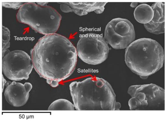
Figure 1.
SEM image of the employed AlSi10Mg powder.
The chemical composition of the powder was kept constant (see Table 2) for all specimens, and hence the conclusions of this study are valid only for this specific set of chemical and process conditions.
Table 2.
Chemical composition of the powder used for the fabrication of specimens in weight percentage.
2.2. Specimen Specification and Finishing
To investigate the influence of heat treatment on the flow and Wöhler (S-N) curves, round tensile and fatigue specimens were designed based on DIN 50125 and ASTM E606/E606M standards [17], respectively. In both cases, the radius of specimens manufactured directly by PBF-LB/M was one millimeter larger than the final dimensions for tests. After machining, specimens were brought to the final dimension with an arithmetic average surface roughness (Ra) of 2 µm, thereby eliminating any irregular surface features, such as balling and satellites inherent to the PBF-LB/M manufacturing process (see Figure 2). It is believed that these surface defects reduce the fatigue strength of SLM parts [18]. In total, 6 tensile specimens and 30 fatigue specimens were fabricated. All specimens were fabricated with their length normal (90°) to the build platform surface. The Archimedes method and image processing of metallography cross-section images were used to measure the relative density of specimens. An average relative density of 99.2 ± 0.3% was measured for all specimens.
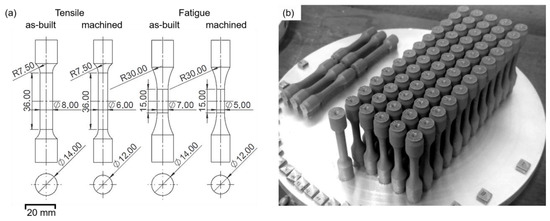
Figure 2.
(a) Geometries of tensile and fatigue specimens before and after machining. (b) The position of specimens on the build-platform.
2.3. Heat Treatment
A heat-treatment procedure was designed based on the conventional T6 heat-treatment to bring the alloy to its peak-hardened condition. To determine the peak-hardened condition, a series of parametric studies on small samples (5 × 5 × 5 mm3) were conducted (see Figure 3). The solution heat-treatments (SHTs) were carried out for different times up to 2 h at 300, 400, and 500 °C. All samples were then quenched in water at room temperature. SHT was followed by artificial aging (AA) at 140, 160, and 180 °C for times up to 48 h (see Table 3). After identifying the adequate parameters, half of the tensile and fatigue specimens were subjected to the selected heat-treatment condition to be brought to the peak-hardened condition. It is worth mentioning that slight dimensional changes are expected due to the relief of residual stresses, formation and dissolution of secondary particles and precipitates, vacancy concentration changes, and redistribution of alloying elements among phases [19,20]. However, such changes were not studied in the present work.
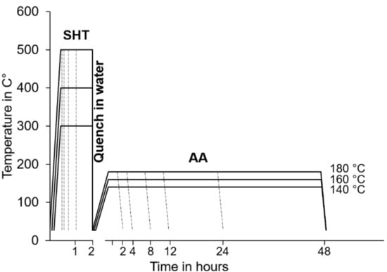
Figure 3.
Schematic representation of the heat-treatment parametric study for both SHT and AA stages.
Table 3.
Heat-treatment conditions used in the parametric study.
The Vickers microhardness values were measured under 600 mN/14 s loading condition, repeated 15 times and averaged. The tensile behavior was evaluated at room temperature and at a strain rate of 2 × 10⁻⁵ 1/s. Fatigue tests were performed under load-controlled condition at a frequency of 20 Hz and a stress ratio of R = −1. Both tensile and fatigue tests were performed using a 25 kN machine (MTS Landmark) equipped with an extensometer. In each condition, 3 tensile and 15 fatigue specimens were tested and averaged to account for statistical deviations.
2.4. Characterization and Testing
Optical microscope (OM, Zeiss Axio Imager 2, Carl Zeiss AG, Oberkochen, BW, Germany) and scanning electron microscope (SEM, Zeiss Auriga, Carl Zeiss AG, Oberkochen, BW, Germany) were employed to examine the microstructure of non-heat-treated (NHT) and heat-treated (HT) specimens as well as the fracture surfaces. Electron backscatter diffraction (EBSD, HKL Nordlys II Detector, HKL Technology Inc., Danbury, CT, USA) and energy-dispersive X-ray (EDX) spectroscopy were used for the detailed analytical work; EBSD and EDX analyses provided information about the crystallographic orientation and chemical composition, respectively. EBSD measurements were performed at an acceleration voltage of 20 kV and a working distance of 14 mm. Orientation maps were acquired for an area of 550 × 400 µm2 with a step size of 2 µm at 200× magnification. The camera was operated at 5 frames averaging in a 4 by 4 binning mode.
Before characterizations, samples were polished down to 0.05 µm. To prepare the samples, the following procedure was carried out: The samples were compression mounted in a conductive compound (Buechler’s KonduktoMeter, Buechler GmbH, Koenigstetten, Austria) and then manually ground down by P1000 grit SiC abrasive paper. This was followed by stepwise automatic mechanical polishing under 20 N load with 9, 3, and then 1 µm polycrystalline diamond suspensions emulsified in an oil-based lubricant. Each step took 7 min. Final polishing was performed for 2 min with MasterMet 2 colloidal silica with a particle size of below 0.05 µm. Samples were cleaned between each step using ethyl alcohol. After final polishing, samples were cleaned with distilled water. No etching was necessary, as a scratch-free surface with sufficient image contrast could be achieved immediately after polishing.
3. Results and Discussion
3.1. Heat Treatment
It is well known that an increase in the ultimate tensile strength () and the yield strength () would enhance the fatigue life [21]. A high yield strength postpones the micro-deformations responsible for fatigue crack initiation. A high tensile strength or a low ratio of , on the other hand, would result in a more effective material hardening during cyclic loading and, therefore, a higher resistance to crack propagation once deformation microbands have formed. Moreover, an increase in hardness indicates an increase in both ultimate and yield strength [22]. Therefore, to minimize the experimental effort and calibrate the heat-treatment process parameters to be applied to the specimens for mechanical tests, heat-treatment conditions associated with maximum hardness were selected. This ensures high strength and fatigue life after heat treatments. The evolution of hardness during heat treatment is shown in Figure 4.
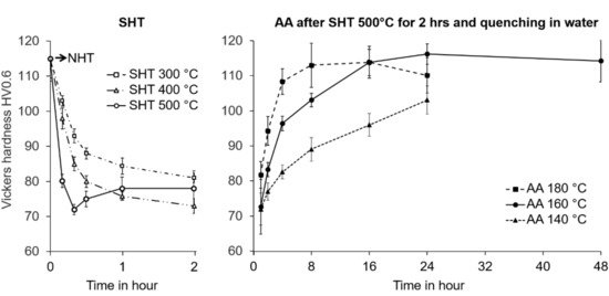
Figure 4.
Microhardness evolution of the alloy during SHT at 300, 400, and 500 °C followed by AA at 140, 160, and 180 °C.
A relatively high hardness, i.e., 115 HV, of AlSi10Mg alloy measured in NHT condition already shows an enhancement compared to that of its conventionally manufactured counterparts, 63 HV [4], which agrees with the data already published [23]. This observation can be justified by the size of columnar and equiaxed grains, in the range of 10 to 70 µm, compared to grain sizes of the order of a few hundred microns in conventionally cast AlSi10Mg [4]. Figure 5 shows the inverse pole figure (IPF) map of the α-Al matrix with a face-centered cubic crystal structure, which is the result of an EBSD analysis of the microstructure in the NHT condition. Despite the presence of equiaxed grains, much of the microstructure is composed of columnar grains with average length and thickness of 70 ± 5 µm and 10 ± 2 µm, respectively. Most columnar grains are oriented with their <001> crystal direction parallel to the build direction. Such a texture has been widely reported in PBF-LB/M-manufactured AlSi10Mg alloy and many other metallic alloys processed by PBF-LB/M [24,25]. It is reported that the morphology and crystal orientation of these columnar grains stay almost intact after solution treatment even at 530 °C for 6 h. Only a slight grain growth can occur [26,27]. This texture arises parallel to the heat extraction direction during columnar solidification of metallic alloys with cubic crystal structures [28]. Equiaxed grains with an average diameter of 8 ± 2 µm and a weaker texture than columnar grains can be observed near the borders of weld beads. The columnar zone is expected to have formed due to the rapid growth of grains with favorable <001> orientation parallel to the heat flow direction. In general, thermal gradient G and solidification rate R at the solid–liquid interface determine the grain morphology during solidification and the morphology transition from equiaxed to columnar [29,30]. In this study, the thermal gradient within the weld bead border, also known as hatch overlaps [31], was found to be as high as 106 K/m, and the solidification rate behind the weld bead had the same speed as the scanning speed, 1.3 m/s, which can explain the rapid growth of grains parallel to the heat flow direction. Both the thermal gradient and solidification rate were calculated based on Rosenthal’s theoretical solution of moving heat source [32] at liquidus–solidus region.
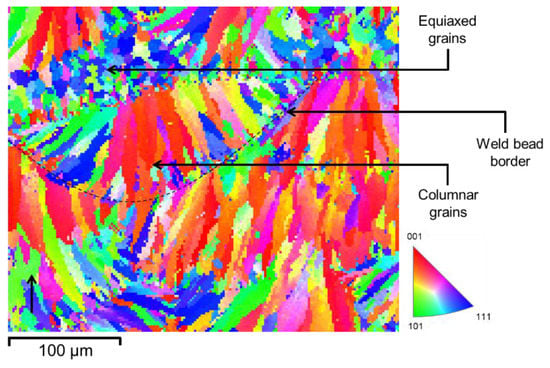
Figure 5.
EBSD IPF map in the NHT condition. Colors indicate crystal directions parallel to the build direction. The black arrow indicates the build direction.
Furthermore, Si supersaturation of up to 2.7 at.% has been reported during the PBF-LB/M of AlSi10Mg alloys [33,34], while the equilibrium solubility of Si in Al is below 0.1 at.% at room temperature. This high supersaturation also contributes to the hardness of the material in the NHT condition. Consequently, grain refinement (Hall–Petch strengthening) and solid solution strengthening resulting from the high solidification rate [1] are both considered as the primary factors for the relatively high hardness of the NHT PBF-LB/M material [35]. In addition, the Orowan strengthening due to the presence of a high density of dispersed Si particles at grain and subgrain boundaries is also expected to have contributed to the high hardness [36].
After SHT at 500 °C for only a few minutes, the material became considerably softer. The microhardness rapidly decreased to 72 HV within 20 min before reversing to 78 HV after an hour of SHT at 500 °C. An initially sharp drop of hardness followed by a steady hardness level at longer holding times has also been reported by Aboulkhair [37]. This sharp reduction in hardness is due to the microstructure coarsening. Moreover, it is also expected that the amount of supersaturated Si in α-Al after quenching from 500 °C be lower than that in the NHT condition [38], thereby diminishing the solid solution strengthening. The small reversion of hardness after 20 min at 500 °C could be attributed to the partial dissolution of coarse intermetallic components and therefore slight solid solution strengthening due to an increase in the solute amounts of elements such as Fe and Si. It is necessary to point out that the hardness decrease was more gradual for SHT at lower temperatures of 400 and 300 °C. Moreover, based on the equilibrium eutectic temperature of nearly 577 °C for the binary Al-Si system, it might appear appropriate to pick a solution heat-treatment temperature higher than 500 °C to dissolve more Si and more intermetallic compounds. Nevertheless, given the presence of alloying elements other than Si and impurities, the risk of incipient melting at a solution heat treatment temperature such as 550 °C would be quite high. On this basis, we picked 500 °C as the solution heat-treatment temperature. Choosing temperatures of this order for the solution heat-treatment of AlSi10Mg is also a common practice according to the literature data [13].
The influence of AA at 140, 160, and 180 °C after two hours of SHT followed by water quenching can also be seen in Figure 4. At 160 °C, the hardness increases to 116 HV after 24 h. The slight hardness decrease after longer aging times indicates the onset of over-aging. When aged at 140 °C, the material could not reach its peak hardness condition in 24 h. On the other hand, when the alloy was aged at 180 °C, its hardness reached a maximum of 114 HV in just 16 h, followed by a relatively sharp drop in hardness due to over-aging. Consequently, for further investigation of the tensile and fatigue behavior of the alloy, an AA time of 24 h and temperature of 160 °C were selected.
The microstructures in the NHT and HT conditions are shown in Figure 6 and Figure 7. In both figures, the white arrows indicate the build direction. As can be seen, hatch overlaps and the three distinct areas, which were visible in NHT condition with “fish scale” morphology [39,40,41], can hardly be identified in HT condition. The three distinct areas are fine subgrains of pro-eutectic (primary) α-Al in the center of the weld bead, larger subgrains on the border of the weld bead, and a heat-affected zone with a broken intercellular network. Similar results have been reported in several publications [38,42,43]. These hatch overlaps disappear through compositional and microstructural homogenization during SHT. The coalescence and coarsening of Si particles during the SHT, as implied from the microstructure in the HT condition, leads to the dissolution of Si-rich eutectic regions. Irregular-shaped Si particles with sizes in the range of 0.2 and 4 µm can clearly be observed in HT condition (Figure 7b). All these would imply the weakening of anisotropic microstructure and mechanical properties of the NHT PBF-LB/M material fabricated either parallel or perpendicular to the build platform. Moreover, several plate-like precipitates with a length of 4 ± 1 µm are distributed in the microstructure. SEM-EDX analyses indicated high concentrations of Fe in the precipitates. These precipitates are expected to be β-Al5SiF [36].
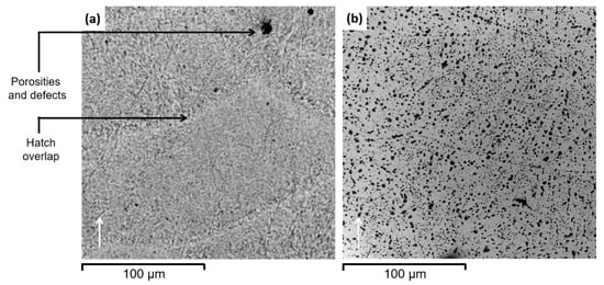
Figure 6.
Cross-sectional optical micrograph of (a) NHT and (b) HT specimens. The white arrow indicates the build direction.
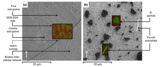
Figure 7.
SEM results showing a cross-section of (a) NHT and (b) HT specimens. The white arrow represents the build direction. EDX map of Al (red) and Si (green) distribution in the area marked by a rectangle is superimposed.
The increase in hardness from 72 to 116 HV after 24 h of artificial aging at 160 °C can be explained by precipitation hardening [44]. Aging is initiated by the formation of Guinier–Preston zones (GP zones) rich in Mg and Si, followed by the formation of metastable phases, e.g., β″ and β’, which eventually evolve to nanoscale β-Mg2Si precipitates [5]. It is also interesting to note that the weight fraction of pro-eutectic α-Al in NHT condition is much higher than what is predicted from the phase diagram under equilibrium, namely 65 wt.% compared to the equilibrium fraction of only 24 wt.%. This observation can be attributed to the nonequilibrium nature of the PBF-LB/M processes.
3.2. Tensile
Figure 8 presents engineering tensile stress–strain curves for NHT and HT specimens. For each condition, the average tensile properties are summarized in Table 4. The results indicate an improvement in both yield strength and ductility in the HT condition. The high work hardening rate of NHT material is due to the presence of dislocations inherent to PBF-LB/M (see texture gradients in NHT, Figure 5). These preexisting dislocations facilitate yielding but tangle quickly, leading to a high work hardening rate. Another contribution to the work hardening rate might have arisen from the partitioning of strain between α-Al and eutectic regions of the material in NHT condition. It could be expected that the strain is initially localized in the softer α-Al. The strain is then gradually transferred to the harder interdendritic regions. In other words, the plastic strain in the α-Al in dendrite cores is larger than the macroscopic (global) strain. This results in a more rapid stress rise (work hardening rate) compared to the case of a uniform strain distribution. A similar observation has also been reported in [45].
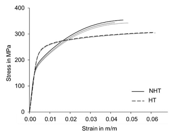
Figure 8.
Engineering tensile stress–strain curves for the NHT and HT conditions.
Table 4.
Tensile properties in NHT and HT conditions.
Typically, in structural metals such as Al-Si alloys, an increase in the strength compromises the ductility, also known as the strength–ductility trade-off [46]. In the present case, however, as in the work of Hitzler et al. [47], both yield strength and ductility were improved after heat treatment. The high strength in the HT is expected to be primarily related to Mg2Si precipitates, which are less likely to form in the NHT condition. The relatively low yield strength in the NHT condition also suggests that the temperature in the gauge section of tensile specimens during PBF-LB/M processing was lower than the build platform temperature. The high strength in the HT condition can also be related to the retention of a fine grain size after SHT, thus preserving the impact of the Hall–Petch strengthening in the HT condition. Enhanced ductility in the HT condition, on the other hand, might be related to a reduction in the residual stresses in the NHT condition.
Different results have been observed in other publications as well. For instance, in [48], the T6 heat-treatment decreased the yield strength but improved the ductility. On the other hand, in [36], the treatment increased yield strength compared to the alloy in NHT condition. These differences may be due to differences in fabrication, heat treatment, and other pre- and post-processing parameters, e.g., preheating temperature, stress relief process, machining, as well as SHT and AA temperature and duration.
3.3. Fatigue
The S-N curves for the NHT and HT conditions during fully reversed loading (R = −1) are shown in Figure 9. The Wöhler curve was fitted according to the Basquin fatigue model, Sa = a (Nf)b, where Sa is the stress amplitude, Nf is the number of cycles to failure, and a and b are the fitting parameters. The survival probability Ps at 90% is depicted as an envelope around the fitted curves as well. The resulting curves show that the heat treatment significantly improved the fatigue life of the alloy in both low and high cyclic loads. The calculated fatigue strength at 107 cycles (SN) for the specimens in HT conditions is approximately 80 MPa, which shows an increase of 60% from NHT fatigue strength of 50 MPa. An increase in SN in the HT condition has also been observed in [49], where 50 MPa and 75 MPa fatigue strength is reported in NHT and HT condition. However, slightly dissimilar results have also been reported [50]. Differences are likely related to the employment of various fabrication process parameters and T6 heat-treatment parameters in individual studies. In contrast to conventionally cast products, fabrication parameters and heat-treatment conditions are currently not well established. It is also important to note the increase in the value of the Basquin slope (b) after heat treatment from −0.16 to −0.19. It illustrates that while there is an overall improvement of fatigue behavior in all stress amplitudes, a greater improvement occurs in the low cycle fatigue behavior.
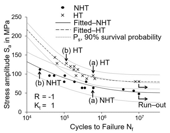
Figure 9.
S-N curves for the NHT and HT conditions. All tests were performed at stress ratio R = −1 and stress concentration factor Kt = 1. Ps denotes the 90% survival probability. The four specimens selected for fractography are marked with letters a and b.
To obtain a complete picture of the influence of the increased yield stress after heat treatment on fatigue life, the modified Goodman method [51] was employed and the fatigue endurance diagram was plotted (see Figure 10). This method reduces the experimental effort by providing an estimate of the fatigue life at different R-values based on one set of measurements at R = −1. This form of representation enables the comparison of the results of this work with already published data based on measurements performed at different R-values. In Figure 10, the knowledge of mechanical properties under tensile loading conditions and SN under fully reversed cyclic loading in the axial direction is used to predict the fatigue performance of materials in NHT and HT conditions under cyclic loading conditions with nonzero mean stress (Sm). It is evident that despite a slight decrease in the ultimate tensile strength, the fatigue life region is expanded by 90% in the HT condition, which is due to the increase in the yield strength after heat treatment. It appears that the delayed onset of micro-deformation caused by the higher yield strength of the alloy in HT condition is the dominant factor controlling the fatigue strength. Moreover, the influence of heat treatment is more pronounced in the negative Sm range.
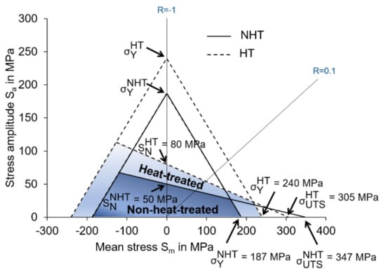
Figure 10.
Modified Goodman diagram for both NHT and HT materials. Yield, ultimate tensile, and fatigue strengths are marked by , , and SN, respectively.
3.4. Fractography
In order to describe better the connection between fatigue properties and features of the fracture surface, e.g., the size, type, and location of defects and the crack initiation and propagation regions, detailed fractography analyses were conducted. Fracture surfaces for two specimens in the NHT condition under Sa = 64 and 112 MPa (Figure 11) and two HT specimens under Sa = 96 and 128 MPa (Figure 12) were examined. The main zones of crack initiation (i), crack propagation (ii), transition area (iii), and final overload fracture (iv) can be observed clearly for all specimens. These zones have been observed in other studies as well [52,53]. The influence of applied Sa on all stages of fracture evolution can be seen, where at lower stresses the fatigue crack propagation and transition region are larger compared to the specimens tested under higher stresses.
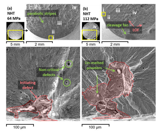
Figure 11.
(a,b) Fracture surfaces of two NHT specimens marked by letters a and b. Top-left: light microscopy images of the whole fracture surface. Top-right: SEM micrograph of the crack initiation and propagation zones. Below: defects responsible for the fatigue fracture initiation.
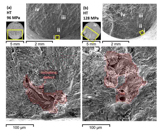
Figure 12.
(a,b) Fracture surfaces of two HT specimens marked by letters a and b. Top-left: light microscopy images of the whole fracture surface. Top-right: SEM micrograph of the crack initiation and propagation zones. Below: defects responsible for the fatigue fracture initiation.
In most cases, the crack initiates from one defect with a size of around 100 to 150 µm on the surface of the specimens. However, as shown in Figure 11b, only at extremely high applied Sa, e.g., 112 MPa, multiple crack initiation sites, i.e., cleavage fans, were observed, rather like the ones reported in [52]. The initiating defects are irregular in shape, while other noncritical smaller defects, i.e., gas pores, remain spherical (Figure 11a). Looking closer, one can detect unmelted aluminum powders within the initiating defects, which indicates a lack of fusion (Figure 11b).
In the fatigue propagation region, a relatively smooth surface, due to repeated compression of the crack, can be observed. In the transition area between crack propagation and final overload fracture, parabolic stripes can be identified, signifying the propagation direction (see Figure 13). At the center of each stripe, a defect could consistently be found. These defects, which are away from the main initiating defect on the surface of the specimens, induce a minor crack initiation and propagation. These cracks can then merge to the main crack propagating on a different plane and form these small parabolic stripes [54].
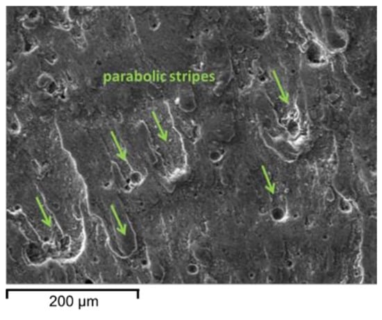
Figure 13.
Fractography at the transition zone between crack initiation and propagation zone of NHT specimens.
In the overload region, large irregular defects due to lack of fusion (LOF) can be observed. At higher magnifications, a quasi-cleavage pattern, i.e., small cleavage facets and dense shear ridges mixed with dimple regions, is visible in the crack propagation zone of the fracture surface, indicating quasi-brittle fracture of NHT specimens (see Figure 14a). After heat treatment, as discussed in Section 3.1, the columnar dendritic α-Al subgrains are fully eliminated, and the eutectic Si network evolves into larger Si particles. Larger dimples are more pronounced on the fracture surface of the HT specimens, indicating an increase in ductility and hence an improvement in low cycle SN of the HT alloys (see Figure 14b).
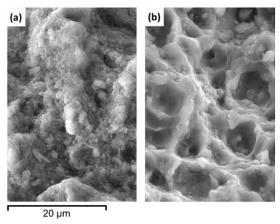
Figure 14.
Fractography at the final overload zone of (a) NHT and (b) HT specimens.
4. Conclusions
Based on the results obtained in this study for the AlSi10Mg alloy, the following conclusions can be drawn:
- The microstructure of the NHT material is mainly composed of columnar grains oriented with their <001> crystal direction parallel to the build direction, which is due to the existence of a high thermal gradient within the hatch overlaps.
- SEM results for the NHT condition indicated a weight fraction of primary α-Al higher than the equilibrium content. This is caused by the rapid solidification conditions. Additionally, the nonequilibrium nature of the process suppresses the growth of secondary dendritic arms in α-Al.
- A relatively high hardness of 115 HV was measured for the NHT condition. It is due to the presence of exceptionally fine grains and a high concentration of supersaturated alloying elements within the aluminum matrix. Another contributing factor to the high hardness is the presence of fine Si particles at the grain and subgrain boundaries. It is also worth mentioning that as hardness is associated with plastic deformation, the good work hardening characteristic of the NHT material, as shown in the tensile test results, must have contributed to its high hardness.
- Solution heat-treatment at 500 °C for two hours followed by quenching and then artificial aging at 160 °C for 24 h was selected after performing a series of parametric studies to bring the alloy to its peak-hardened condition. After the heat treatment, columnar dendritic subgrains, as well as hatch overlaps, disappear through compositional homogenization, which implies the elimination of the anisotropic microstructural and mechanical properties of the NHT material. At peak-hardened condition, the hardness of 116 HV was measured, which is primarily caused by precipitation hardening of the alloy with nanoscale β-Mg2Si precipitates.
- The flow curves indicate a simultaneous improvement of both yield strength and tensile elongation in HT condition. This can be explained very well by the following effects: Firstly, the residual stress accumulated in the specimen during the PBF-LB/M process is recovered after the heat treatment, thus reducing the probability of fracture in regions of the NHT specimen under high local stresses. Secondly, the impact of the Hall–Petch strengthening factor is preserved after heat treatment, as the grain size after SHT remains similar to that observed in NHT condition. Lastly, Mg2Si precipitation further contributes to strengthening.
- Although there is a slight decrease in the ultimate tensile strength, fatigue life after heat treatment is improved because of an increase in the yield strength. Moreover, in both NHT and HT specimens, fatigue failure is initiated from large defects located just below or on the specimen surface for all stress levels. The heat treatment did not have much influence on the size of initiating defects, which were typically of the order of 100 to 150 µm.
- The fracture mechanism after heat treatment changes from quasi-brittle to a more ductile type. Fracture surface examinations indicated that the quasi-cleavage pattern of the alloy in the NHT condition converts into relatively larger dimples in the crack propagation zone in the HT condition.
Author Contributions
F.S. carried out the main characterization and analyses of the data and wrote the original draft of the paper. J.-M.T. and A.C.D. partly performed the tensile and fatigue tests. N.B. conducted the SEM and EBSD imagining. J.M. provided support in the conceptualization, as well as refining the project idea and methodology, and edited the manuscript. S.S. supervised the project, reviewed the manuscript, and completed the final editing. All authors have read and agreed to the published version of the manuscript.
Funding
This research received no external funding.
Data Availability Statement
The data presented in this study are openly available in FigShare at doi.org/10.6084/m9.figshare.14458947.v1.
Acknowledgments
The authors gratefully acknowledge the support of their colleagues at the Institute of Laser Technologies (IFSW), University of Stuttgart, and the infrastructure made available by TRUMPF GmbH + Co. KG in the ARENA2036 e.V. research building for the fabrication of the samples.
Conflicts of Interest
The authors declare no conflict of interest. The funders had no role in the design of the study; in the collection, analyses, or interpretation of data; in the writing of the manuscript; or in the decision to publish the results.
References
- Yan, C.; Hao, L.; Hussein, A.; Young, P.; Huang, J.; Zhu, W. Microstructure and mechanical properties of aluminium alloy cellular lattice structures manufactured by direct metal laser sintering. Mater. Sci. Eng. A 2015, 628, 238–246. [Google Scholar] [CrossRef]
- Dai, D.; Gu, D.; Poprawe, R.; Xia, M. Influence of additive multilayer feature on thermodynamics, stress and microstructure development during laser 3D printing of aluminum-based material. Sci. Bull. 2017, 62, 779–787. [Google Scholar] [CrossRef]
- Kadkhodapour, J.; Montazerian, H.; Darabi, A.C.; Anaraki, A.P.; Ahmadi, S.M.; Zadpoor, A.A.; Schmauder, S. Failure mechanisms of additively manufactured porous biomaterials: Effects of porosity and type of unit cell. J. Mech. Behav. Biomed. Mater. 2015, 50, 180–191. [Google Scholar] [CrossRef] [PubMed]
- Girelli, L.; Tocci, M.; Gelfi, M.; Pola, A. Study of heat treatment parameters for additively manufactured AlSi10Mg in comparison with corresponding cast alloy. Mater. Sci. Eng. A 2019, 739, 317–328. [Google Scholar] [CrossRef]
- Izcara, X.L.; Blank, A.G.; Pyczak, F.; Staron, P.; Schumann, S.; Huber, N. Characterization and modeling of the influence of artificial aging on the microstructural evolution of age-hardenable AlSi10Mg(Cu) aluminum alloys. Mater. Sci. Eng. A 2014, 610, 46–53. [Google Scholar] [CrossRef]
- Romano, S.; Brückner-Foit, A.; Brandão, A.; Gumpinger, J.; Ghidini, T.; Beretta, S. Fatigue properties of AlSi10Mg obtained by additive manufacturing: Defect-based modelling and prediction of fatigue strength. Eng. Fract. Mech. 2018, 187, 165–189. [Google Scholar] [CrossRef]
- Trevisan, F.; Calignano, F.; Lorusso, M.; Pakkanen, J.; Aversa, A.; Ambrosio, E.P.; Lombardi, M.; Fino, P.; Manfredi, D. On the Selective Laser Melting (SLM) of the AlSi10Mg Alloy: Process, Microstructure, and Mechanical Properties. Materials 2017, 10, 76. [Google Scholar] [CrossRef]
- Aboulkhair, N.T.; Maskery, I.; Tuck, C.; Ashcroft, I.; Everitt, N.M. Improving the fatigue behaviour of a selectively laser melted aluminium alloy: Influence of heat treatment and surface quality. Mater. Des. 2016, 104, 174–182. [Google Scholar] [CrossRef]
- Mfusi, B.J.; Mathe, N.R.; Tshabalala, L.C.; Popoola, P.A. The Effect of Stress Relief on the Mechanical and Fatigue Properties of Additively Manufactured AlSi10Mg Parts. Metals 2019, 9, 1216. [Google Scholar] [CrossRef]
- Beretta, S.; Gargourimotlagh, M.; Foletti, S.; Du Plessis, A.; Riccio, M. Fatigue strength assessment of “as built” AlSi10Mg manufactured by SLM with different build orientations. Int. J. Fatigue 2020, 139, 105737. [Google Scholar] [CrossRef]
- Tang, M.; Pistorius, P.C. Fatigue life prediction for AlSi10Mg components produced by selective laser melting. Int. J. Fatigue 2019, 125, 479–490. [Google Scholar] [CrossRef]
- Zhuo, L.; Wang, Z.; Zhang, H.; Yin, E.; Wang, Y.; Xu, T.; Li, C. Effect of post-process heat treatment on microstructure and properties of selective laser melted AlSi10Mg alloy. Mater. Lett. 2019, 234, 196–200. [Google Scholar] [CrossRef]
- Bhaduri, D.; Penchev, P.; Essa, K.; Dimov, S.; Carter, L.N.; Pruncu, C.I.; Pullini, D. Evaluation of surface/interface quality, microstructure and mechanical properties of hybrid additive-subtractive aluminium parts. CIRP Ann. 2019, 68, 237–240. [Google Scholar] [CrossRef]
- Wadell, H. Volume, Shape, and Roundness of Rock Particles. J. Geol. 1932, 40, 443–451. [Google Scholar] [CrossRef]
- Brika, S.E.; Letenneur, M.; Dion, C.A.; Brailovski, V. Influence of particle morphology and size distribution on the powder flowability and laser powder bed fusion manufacturability of Ti-6Al-4V alloy. Addit. Manuf. 2020, 31, 100929. [Google Scholar] [CrossRef]
- Cordova, L.; Campos, M.; Tinga, T. Revealing the Effects of Powder Reuse for Selective Laser Melting by Powder Characterization. JOM 2019, 71, 1062–1072. [Google Scholar] [CrossRef]
- E08 Committee. Test. Method for Strain-Controlled Fatigue Testing; ASTM International: West Conshohocken, PA, USA, 2019. [Google Scholar]
- Frazier, W.E. Metal Additive Manufacturing: A Review. J. Mater. Eng. Perform. 2014, 23, 1917–1928. [Google Scholar] [CrossRef]
- Song, Y.F.; Ding, X.F.; Xiao, L.R.; Zhao, X.J.; Cai, Z.Y.; Guo, L.; Li, Y.W.; Zheng, Z.Z. Effects of two-stage aging on the dimensional stability of Al-Cu-Mg alloy. J. Alloy. Compd. 2017, 701, 508–514. [Google Scholar] [CrossRef]
- Osten, J.; Milkereit, B.; Reich, M.; Yang, B.; Springer, A.; Nowak, K.; Kessler, O. Development of Precipitation Hardening Parameters for High Strength Alloy AA 7068. Materials 2020, 13, 918. [Google Scholar] [CrossRef] [PubMed]
- Dieter, G.E.; Bacon, D. Mechanical Metallurgy; McGraw-Hill: London, UK, 1988. [Google Scholar]
- Pavlina, E.J.; van Tyne, C.J. Correlation of Yield Strength and Tensile Strength with Hardness for Steels. J. Mater. Eng. Perform. 2008, 17, 888–893. [Google Scholar] [CrossRef]
- Maamoun, A.H.; Xue, Y.F.; Elbestawi, M.A.; Veldhuis, S.C. The Effect of Selective Laser Melting Process Parameters on the Microstructure and Mechanical Properties of Al6061 and AlSi10Mg Alloys. Materials 2018, 12, 12. [Google Scholar] [CrossRef]
- Hadadzadeh, A.; Amirkhiz, B.S.; Odeshi, A.; Mohammadi, M. Dynamic loading of direct metal laser sintered AlSi10Mg alloy: Strengthening behavior in different building directions. Mater. Des. 2018, 159, 201–211. [Google Scholar] [CrossRef]
- Montero-Sistiaga, M.L.; Mertens, R.; Vrancken, B.; Wang, X.; van Hooreweder, B.; Kruth, J.-P.; Van Humbeeck, J. Changing the alloy composition of Al7075 for better processability by selective laser melting. J. Mater. Process. Technol. 2016, 238, 437–445. [Google Scholar] [CrossRef]
- Takata, N.; Kodaira, H.; Sekizawa, K.; Suzuki, A.; Kobashi, M. Change in microstructure of selectively laser melted AlSi10Mg alloy with heat treatments. Mater. Sci. Eng. A 2017, 704, 218–228. [Google Scholar] [CrossRef]
- Yang, P.; Rodriguez, M.A.; Deibler, L.A.; Jared, B.H.; Griego, J.; Kilgo, A.; Allen, A.; Stefan, D.K. Effect of thermal annealing on microstructure evolution and mechanical behavior of an additive manufactured AlSi10Mg part. J. Mater. Res. 2018, 33, 1701–1712. [Google Scholar] [CrossRef]
- Flemings, M.C. Solidifications Processing; McGraw-Hill: New York, NY, USA, 1974. [Google Scholar]
- Hadadzadeh, A.; Amirkhiz, B.S.; Li, J.; Mohammadi, M. Columnar to equiaxed transition during direct metal laser sintering of AlSi10Mg alloy: Effect of building direction. Addit. Manuf. 2018, 23, 121–131. [Google Scholar] [CrossRef]
- Hunt, J.D. Steady state columnar and equiaxed growth of dendrites and eutectic. Mater. Sci. Eng. 1984, 65, 75–83. [Google Scholar] [CrossRef]
- Prashanth, K.G.; Scudino, S.; Klauss, H.J.; Surreddi, K.B.; Löber, L.; Wang, Z.; Chaubey, A.K.; Kühn, U.; Eckert, J. Microstructure and mechanical properties of Al–12Si produced by selective laser melting: Effect of heat treatment. Mater. Sci. Eng. A 2014, 590, 153–160. [Google Scholar] [CrossRef]
- Rosenthal, D. Mathematical Theory of Heat Distribution during Welding and Cutting. Weld. J. 1941, 20, 220–234. [Google Scholar]
- Marola, S.; Manfredi, D.; Fiore, G.; Poletti, M.G.; Lombardi, M.; Fino, P.; Battezzati, L. A comparison of Selective Laser Melting with bulk rapid solidification of AlSi10Mg alloy. J. Alloy. Compd. 2018, 742, 271–279. [Google Scholar] [CrossRef]
- Van Cauwenbergh, P.; Samaee, V.; Thijs, L.; Nejezchlebová, J.; Sedlák, P.; Iveković, A.; Schryvers, D.; Van Hooreweder, B.; Vanmeensel, K. Unravelling the multi-scale structure-property relationship of laser powder bed fusion processed and heat-treated AlSi10Mg. Sci. Rep. 2021, 11, 6423. [Google Scholar] [CrossRef] [PubMed]
- Maeshima, T.; Oh-Ishi, K. Solute clustering and supersaturated solid solution of AlSi10Mg alloy fabricated by selective laser melting. Heliyon 2019, 5, e01186. [Google Scholar] [CrossRef]
- Zhou, L.; Mehta, A.; Schulz, E.; McWilliams, B.; Cho, K.; Sohn, Y. Microstructure, precipitates and hardness of selectively laser melted AlSi10Mg alloy before and after heat treatment. Mater. Charact. 2018, 143, 5–17. [Google Scholar] [CrossRef]
- Aboulkhair, N.T.; Tuck, C.; Ashcroft, I.; Maskery, I.; Everitt, N.M. On the Precipitation Hardening of Selective Laser Melted AlSi10Mg. Metall. Mat. Trans. A 2015, 46, 3337–3341. [Google Scholar] [CrossRef]
- Iturrioz, A.; Gil, E.; Petite, M.M.; Garciandia, F.; Mancisidor, A.M.; Sebastian, M.S. Selective laser melting of AlSi10Mg alloy: Influence of heat treatment condition on mechanical properties and microstructure. Weld. World 2018, 62, 885–892. [Google Scholar] [CrossRef]
- Rosenthal, I.; Stern, A.; Frage, N. Microstructure and Mechanical Properties of AlSi10Mg Parts Produced by the Laser Beam Additive Manufacturing (AM) Technology. Metallogr. Microstruct. Anal. 2014, 3, 448–453. [Google Scholar] [CrossRef]
- Nahmany, M.; Rosenthal, I.; Benishti, I.; Frage, N.; Stern, A. Electron beam welding of AlSi10Mg workpieces produced by selected laser melting additive manufacturing technology. Addit. Manuf. 2015, 8, 63–70. [Google Scholar] [CrossRef]
- Asgari, H.; Baxter, C.; Hosseinkhani, K.; Mohammadi, M. On microstructure and mechanical properties of additively manufactured AlSi10Mg_200C using recycled powder. Mater. Sci. Eng. A 2017, 707, 148–158. [Google Scholar] [CrossRef]
- Liu, X.; Zhao, C.; Zhou, X.; Shen, Z.; Liu, W. Microstructure of selective laser melted AlSi10Mg alloy. Mater. Des. 2019, 168, 107677. [Google Scholar] [CrossRef]
- Silbernagel, C.; Ashcroft, I.; Dickens, P.; Galea, M. Electrical resistivity of additively manufactured AlSi10Mg for use in electric motors. Addit. Manuf. 2018, 21, 395–403. [Google Scholar] [CrossRef]
- Lefebvre, W.; Rose, G.; Delroisse, P.; Baustert, E.; Cuvilly, F.; Simar, A. Nanoscale periodic gradients generated by laser powder bed fusion of an AlSi10Mg alloy. Mater. Des. 2021, 197, 109264. [Google Scholar] [CrossRef]
- Hitzler, L.; Janousch, C.; Schanz, J.; Merkel, M.; Heine, B.; Mack, F.; Hall, W.; Öchsner, A. Direction and location dependency of selective laser melted AlSi10Mg specimens. J. Mater. Process. Technol. 2017, 243, 48–61. [Google Scholar] [CrossRef]
- Ritchie, R.O. The conflicts between strength and toughness. Nat. Mater. 2011, 10, 817–822. [Google Scholar] [CrossRef]
- Hitzler, L.; Charles, A.; Öchsner, A. The Influence of Post-Heat-Treatments on the Tensile Strength and Surface Hardness of Selective Laser Melted AlSi10Mg. DDF 2017, 370, 171–176. [Google Scholar] [CrossRef]
- Fousová, M.; Dvorský, D.; Michalcová, A.; Vojtěch, D. Changes in the microstructure and mechanical properties of additively manufactured AlSi10Mg alloy after exposure to elevated temperatures. Mater. Charact. 2018, 137, 119–126. [Google Scholar] [CrossRef]
- Bagherifard, S.; Beretta, N.; Monti, S.; Riccio, M.; Bandini, M.; Guagliano, M. On the fatigue strength enhancement of additive manufactured AlSi10Mg parts by mechanical and thermal post-processing. Mater. Des. 2018, 145, 28–41. [Google Scholar] [CrossRef]
- Zhang, C.; Zhu, H.; Liao, H.; Cheng, Y.; Hu, Z.; Zeng, X. Effect of heat treatments on fatigue property of selective laser melting AlSi10Mg. Int. J. Fatigue 2018, 116, 513–522. [Google Scholar] [CrossRef]
- Goodman, J. Mechanics Applied to Engineering; Longmans, Green and Co.: London, UK, 1919. [Google Scholar]
- Uzan, N.E.; Shneck, R.; Yeheskel, O.; Frage, N. Fatigue of AlSi10Mg specimens fabricated by additive manufacturing selective laser melting (AM-SLM). Mater. Sci. Eng. A 2017, 704, 229–237. [Google Scholar] [CrossRef]
- Beevers, E.; Brandão, A.D.; Gumpinger, J.; Gschweitl, M.; Seyfert, C.; Hofbauer, P.; Rohr, T.; Ghidini, T. Fatigue properties and material characteristics of additively manufactured AlSi10Mg—Effect of the contour parameter on the microstructure, density, residual stress, roughness and mechanical properties. Int. J. Fatigue 2018, 117, 148–162. [Google Scholar] [CrossRef]
- Xu, Z.W.; Wang, Q.; Wang, X.S.; Tan, C.H.; Guo, M.H.; Gao, P.B. High cycle fatigue performance of AlSi10mg alloy produced by selective laser melting. Mech. Mater. 2020, 148, 103499. [Google Scholar] [CrossRef]
Publisher’s Note: MDPI stays neutral with regard to jurisdictional claims in published maps and institutional affiliations. |
© 2021 by the authors. Licensee MDPI, Basel, Switzerland. This article is an open access article distributed under the terms and conditions of the Creative Commons Attribution (CC BY) license (https://creativecommons.org/licenses/by/4.0/).