Abstract
Modern forming processes often allow today the efficient production of complex parts. In order to increase the sustainability of forming processes it would be favorable if the forming of workpieces becomes possible using production waste. At the Chair of Forming and Machining Technology of the Paderborn University (LUF) research is presently conducted with the overall goal to produce workpieces directly from secondary aluminum (e.g., powder and chips). Therefore, friction-based forming processes like friction spinning (or cognate processes) are used due to their high efficiency. As a pre-step, the production of semi-finished parts was the subject of accorded research work at the LUF. Therefore, a friction-based hot extrusion process was used for the full recycling or rework of aluminum chips into profiles. Investigations of the recycled semi-finished products show that they are comparable to conventionally produced semi-finished products in terms of dimensional stability and shape accuracy. An analysis of the mechanical properties of hardness and tensile strength shows that a final product with good and homogeneously distributed properties can be produced. Furthermore, significant correlations to the friction spinning process could be found that are useful for the above-mentioned direct part production from secondary aluminum.
1. Introduction
In recent years, there has been an increasing demand for more flexible manufacturing systems to produce customizable complex products. Flexible manufacturing processes for the user-specific production of workpieces with graded properties, such as friction spinning, form the basis for this. Friction spinning is a highly energy-efficient process, since the components can be produced with fairly low demands regarding the equipment and small amounts of energy [1]. In order to also optimize the products in terms of sustainability, it is important to design the procurement of raw materials in an energy- and material-efficient manner in addition to an efficient manufacturing strategy. Here, the use of primary aluminum represents the most energy-intensive procurement strategy. The conventional recycling process consumes less energy, but also results in environmental pollution due to the salt slag produced. A further objective of the present study is the preparation of a fully energy-efficient process for the direct production of end products from secondary aluminum. For this purpose, a suitable recycling process is identified in a first step.
In the field of extrusion, some research work has already been carried out on producing semi-finished products from aluminum scrap [2]. The aim of the research work described in this paper is to verify the feasibility of a friction-induced recycling process for aluminum chips. In future, these semi-finished products are to be further processed using the friction-induced spinning process, which is also energy-efficient, in order to create a fully efficient and sustainable production chain.
The friction spinning process has been intensively researched in recent years at the Chair of Forming and Machining Technology at the University of Paderborn. In the friction spinning process, a wide variety of parameters, such as the rotational speed and the feed can influence the workpiece or tool movement and the resulting contact [3]. An exact description and explanation of the underlying phenomena for this complex process with a rotating workpiece movement and a large number of additional influencing process parameters are therefore difficult. An investigation of the less complex friction-induced recycling process, which has a number of similarities with the continuous recycling process, should also contribute to the research into the friction spinning process.
As the first step in introducing the friction-induced recycling process, an explanation is given of related processes which also deal with the optimization of the conventional recycling process of aluminum chips. A number of methods have been developed for optimizing the existing process of secondary aluminum production as well as for creating new possibilities for semi-finished products. One possibility is direct hot extrusion of chips from turning and milling processes with prior compression of the chips into blocks. The use of pre-compacted blocks of aluminum chips in the extrusion process produces semi-finished products whose mechanical properties are comparable to those of conventional cast aluminum billets. If high process temperatures and elongation rates are guaranteed within the process, the result is almost independent of the compaction process and the chip size [2]. Investigations on the influence of the tool geometry and thus also of the material flow show that a tool with integrated equal channel angular pressing (iECAP) leads to a better welding of the chips. The mechanical properties determined by hardness measurements and tensile tests could also be improved by using an iECAP tool [4]. The processing of the recycled chips can take place in one or two stages. In past studies, the pre-compacted chips were first processed into a semi-finished product using hot extrusion and then into shafts and cans using a second process step, cold reverse extrusion. It has been shown that the forces to be applied during extrusion are comparable for conventional semi-finished products and those made from chips. The same applies to the quality of the surface for both the different starting materials for the impact extrusion process [5]. Another possibility for recycling metallic scrap is friction stir extrusion. Here, the heat and pressure required for extrusion are generated by the die. Imperfections in the wires produced could be attributed to non-optimal process parameter combinations. It can be shown that a high rotational speed of the die is essential for a successful process. The wires produced with the optimal process parameters showed up to 80% of the tensile strength of the raw material [6].
Another promising concept is that of continuous extrusion, on which the process used in this paper is based. The concept of continuous extrusion was first investigated in the 1970s. Designed in the UK, it is also called the conform-process [7]. Considering the biggest disadvantage of the conventional extrusion process, a process has been designed which uses the friction between the tool and the feedstock material to generate heat and extrude the material through the die. In the first attempt the process was designed as an alternative to the conventional wire drawing process for creating semi-finished products with different geometries [7]. The feasibility of recycling (aluminum) rejects using the process principle of continuous extrusion was investigated in a research project, but was not pursued further for reasons that are incomprehensible from today’s perspective [8]. In view of the central aspects of energy-efficient and sustainable production today, this process needs to be further researched. Research work on the production of semi-finished products made from (titanium) powder has also been done [9,10]. Recently, the possibility of recycling titanium chips in a conventional Conform machine has also been investigated. However, the wire produced from the titanium alloy chips still has inconsistent tool filling and a poor surface finish [11]. Regardless of the filling medium, the same principle of continuous extrusion is used in all the previously described investigations. The feedstock is filled into the groove of the wheel and compressed by the tool. Indicating a rise in temperature and pressure, the feedstock is carried by the grooved wheel until it hits the abutment from where it is extruded into a profiled die.
The subject of the research described in this paper is a detailed investigation of a friction-induced, energy-efficient and direct manufacturing process of semi-finished products. Compared to some studies on such process principles described in the literature, a good end product can be produced in terms of mold filling and quality. The self-induced heating process, the electrical power to be applied, as well as the results of the material testing are explained in detail, thus demonstrating in detail the feasibility presented in the literature.
2. Machine Design
A continuously variable, powerful gear motor with a nominal output torque of 19,000 Nm forms the basis of the test rig established at the Chair of Forming and Machining Technology for the friction-induced recycling process of aluminum chips. Within the control system it is possible to record the key data of the mechanical and electrical performance. A grooved wheel is attached to the gear motor shaft. Figure 1a shows a sketch of the process for friction-induced recycling of aluminum chips used at the Chair of Forming and Machining, which is presented in this paper. The grooved wheel is surrounded on almost one quarter of its circumference on the right side by the tool holder with the hardened tool insert. Due to the fact that the tool insert is not coaxial to the wheel, its cross section is narrowed steadily by the tool insert. During operation, the (aluminum) chips are filled continuously into the groove of the wheel. The rotary movement of the wheel takes the chips along into the tool. At the beginning of the area in which the wheel runs in the tool, the reduction in cross-section is still small, so that the chips are only slightly compressed, as can be seen in Figure 1b section A-A. The steady compression through the decreasing cross-section leads to a rise in the density together with the increase of tool and chip temperature due to friction (Figure 1b section B-B). Before the end of the compression channel is reached, the chips are fully compressed and placified (section C-C). The tool design in this area prevents undesired extrusion of the material through the narrow gap between the wheel and the tool. Following deflection at the end of the channel, the material is pressed through a shaping die to obtain the final shape. The extrusion pressure required for this is generated due to the friction-induced transport of the material caused by the rotation of the wheel. The pressure required for extrusion is generated in two zones, which can be distinguished by the degree of compression. These two zones were already defined by Etherington in 1974 for the forming of wires and will be added and modified in the follow-up to the application of the recycling of chips [7].
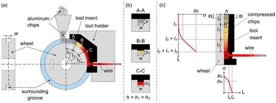
Figure 1.
Tooling concept of the friction-induced recycling process of (aluminum) chips. (a) Machine assembly. (b) Cross-section reduction of the wheel groove by the tool. (c) Distribution of the extrusion pressure inside the groove and the die.
Until the wheel groove is completely filled at the end of the filling zone (l0), no forces can be transmitted due to the insufficient density of the groove. From the point at which the groove cross-section is completely filled with chips, the chips are further compacted and thus the density is also increased. The so-called grip zone (l1) ends when the groove is completely filled with material and there are no more air inclusions, etc. The (partially) compacted material present in the grip zone is able to transmit forces due to the gripping between the side walls of the groove. However, the extrusion pressure in the grip zone due to the molding of the material into the groove cross-section is small by comparison to the flow zone (l2). At the beginning of the flow zone, the material is highly compacted, but no metallic bond exists between the chips yet. This is steadily achieved within the flow zone due to the high temperature and the high pressure. It is therefore assumed that a homogeneous material has formed by the end of the flow zone, which is shaped by the die. The extrusion pressure is reduced as shown in Figure 1c due to the deflection of the material flow by the counterholder and the friction within the die during the forming process.
3. Materials and Methods
In the following experiments, the wrought aluminum alloy EN-AW-6060 is used. The machining of this ductile aluminum alloy leads to uniform chip formation. Underlying process parameters of the associated milling process as well as a geometric characterization are shown in Table 1. Using a conventional dry-milling process, the chips are created from a tube. Figure 2 shows the tool, an 8-bladed milling tool with a diameter of 63 mm, which has been used to produce the chips. In the investigations described in this paper, the chips are not subjected to any pretreatment. However, the aim of further investigations is to uncover the influences of (electrochemical) pretreatment on the mechanical and optical properties of the semi-finished products manufactured. Further influences due to impurities or machining residues (e.g., cooling lubricants) are also to be eliminated by means of pretreatment.

Table 1.
Machining parameters for the production and geometric characterization of the chips.
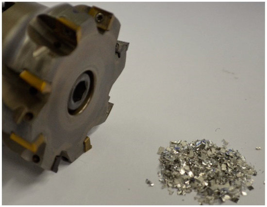
Figure 2.
In the studies used chips and the associated tool.
Following the description of the initial state, the process used for recycling the aluminum chips is now explained. During the development of the friction-induced chip recycling process, it has been shown that a high tool temperature is needed to create a continuous extrusion process. To reach these temperatures, two approaches are possible. The first approach is the use of heating elements. Electric cartridge heaters are frequently used in the field of forming technology to increase or maintain a defined temperature in certain areas of a tool.
Due to the continuous rotational movement of the wheel, the cartridge heaters can only be used to heat the stationary tools. Within the scope of this challenge, a self-induced approach has been used to achieve the necessary tool temperature. From the beginning of the process, a small quantity of chips is filled into the grooved wheel. The chips settle in the narrow gap between the tool and the wheel. The rotating wheel rubs against the chips and heat is generated.
Setting a stationary process represents a central aspect for achieving reliable production of continuous semi-finished products. One way of determining a possible steady state is to consider the torque to be applied by the gear motor. The torque is recorded via the electrical power consumption of the frequency inverter. Due to the fact that there is a continuous electrical control to maintain the specified speed, the power consumed and therefore the torque varies over an average value. This and the formation of the corresponding average value is shown in Figure 3a. Applied to the entire curve, the torque and speed curve shown in Figure 3b are obtained. The torque curve can be divided into different process phases. In the first and the sixth phases, the machine is switched off, and the speed and torque are equal to zero. At the start of the second phase, the gear motor is switched on. When the engine is idling without feedstock, an average torque of M2 = 850 Nm is measured.
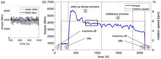
Figure 3.
Change in speed and torque in the different process stages of the recycling process of EN-AW-6060 chips with a round 5 mm die and a rotational speed of 6 rpm. (a) Determination of an equalization curve for the original data. (b) Visualization of the change in torque over the speed.
At the beginning of the third process phase, the torque is noticeably increased by the supplied feedstock. After reaching the maximum value Mmax = 5650 Nm, the torque decreases over the next few minutes with the continuous addition of further feedstock. After ten minutes of processing, a nearly stationary process is attained in terms of the torque of M3 = 3680 Nm. Idling also occurs in the fifth process phase. However, due to the material build-up between the wheel and the tool and the resulting higher friction, the average torque of M = 2900 Nm here is significantly higher than the value before filling with feedstock.
Due to the complex tool system and the high pressure, a direct temperature measurement in the extrusion chamber is not possible at the current time. As an alternative, the temperature can be measured at three points at a distance from the extrusion chamber. To a certain extent, the true temperature curve in the extrusion chamber can be inferred from these measuring points. The development of the temperature at three points on the outside of the tool is shown in Figure 4a. For the position of the measuring points, see the corresponding sketch in Figure 4b. In this case, measuring points p1 and p2 are located approximately 6 mm below and above the center of the extrusion channel, respectively.
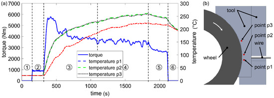
Figure 4.
Determination of the dependence of the process variables in the test with EN-AW-6060 chips, a round die of 5 mm and a rotational speed of 6 rpm. (a) Development of the torque and the external tool temperatures. (b) Illustration of the temperature measuring points.
At the beginning of the process, the temperatures rise sharply, with the temperature of measuring points p1 and p2 closer to the extrusion chamber showing a higher increase. As the process continues, the temperature of all the measuring points increases only slightly. Because of their identical distance from the extrusion chamber, measuring points p1 and p2 show an almost identical temperature curve. Due to the fact that, in the stationary range, there is only a small temperature increase at the measuring points which are not too far away from the extrusion chamber, an approximation of the true temperature curve can be generated with this measuring method. In future studies, an FEM compensation calculation is planned for determining the true temperature in the extrusion chamber. Following the first start-up, the degressive course of the torque can be explained by the rising temperature. The yield stress and thus the resistance to the forming of the aluminum chips decreases as the temperature rises. As a result, the torque that needs to be provided by the geared motor in order to form and extrude the chips, decreases.
4. Results and Discussion
4.1. Welding Quality
The process strategy of friction-induced heating is identified as one of the possible factors influencing the quality of the products produced. Figure 5a–c show a cross-section of three different pieces of EN-AW-6060 wire that were extruded at different times with a rotational speed of 6 rpm. In Figure 5d,e the wire extruded at approximately 800 s is shown in further views to demonstrate the good quality of the surface.
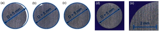
Figure 5.
Dependence of semi-finished product quality on process time and temperature. (a) Extrusion after 420 s shows strong deviations from the ideal geometry. (b) After 600 s, only minor imperfections, (c–e). After 800 s, a good wire is extruded in terms of both die filling and surface quality.
The wire extruded after approximately 420 s shows strong deviations from the nominal cross-section of d = 5 mm. The sample taken after approximately 600 s shows only a minor imperfection. After approximately 800 s, a nearly stationary process is attained, and the wire has a complete and defect-free cross-section with a macroscopically smooth surface. Using a rotational speed of 6 rpm, the production rate of the friction-induced recycling process is about 5 mm/s. In a comparable extrusion process, a production rate of 20 mm/s has been set [12]. An improvement/increase of the discharge rate of the friction-induced recycling process by increasing the rotational speed, but also by increasing the filling rate or generally enlarging the system, is conceivable and reasonable.
4.2. Hardness Distribution
One way of assessing the mechanical properties of the semi-finished products is to consider the hardness. The focus of the first observation is on the hardness distribution over the entire cross-sectional area of the semi-finished product. Figure 6a shows the hardness of 13 measuring points distributed uniformly over the cross-sectional area of an extruded wire with a diameter of 5 mm. Each of the measuring points has been determined at the adequate positions with a Nexus 4000 hardness tester from the Innovatest Company, Maastricht, The Netherlands, employing the Vickers HV 0.3 method. The distances between the measuring points as well as the specimen edge are selected according to DIN EN ISO 6507-1 [13]. The mean value of the hardness is 55.2 HV 0.3. Smaller deviations in hardness occur over the entire cross-sectional area of the wire, but these are less than 5% of the mean value. It can therefore be concluded that the semi-finished product has homogeneous properties in terms of its hardness over the cross-sectional area. A gradient of this mechanical property could not be determined.
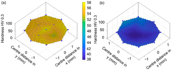
Figure 6.
Hardness distribution over the cross-sectional area of (a) EN-AW-6060 wire extruded with a rotational speed of 6 rpm, (b) EN-AW-6060 reference specimen.
For a comparison of the mechanical properties of the wire produced by the friction-induced process with a reference product, both samples must be in a comparable delivery condition. Due to the strong temperature effect as well as the forming by the friction-induced extrusion process, it can be assumed that a condition similar to solution annealing exists, following the process presented in this paper. The reference samples, also made of EN-AW-6060, have a diameter of 4 mm and are extruded. To perform a comparison of the mechanical properties, the reference specimens are solution annealed. Subsequently, the hardness of the extruded reference sample of 42.8 HV 0.3 (see Figure 6b) is found to be about 22% lower than that of the wire produced by the friction-induced extrusion process. A possible explanation for this phenomenon can be seen in the grain size refinement of the friction-induced recycling process.
4.3. Tensile Testing
In addition to hardness testing, the mechanical properties of the semi-finished products made by the innovative recycling process are also assessed based on the results of tensile tests. A Z100 tensile-compression testing machine from the ZwickRoell company, Ulm (Germany) is used. All four specimens tested exhibit almost identical behavior in the elastic strain range, as shown in Figure 7. Parameters belonging to the stress-strain curves are shown in Table 2. The average 0.2% proof stress is 113.3 MPa. In the plastic strain range, the behavior of the four specimens deviates slightly. However, these deviations are not of further importance due to the similar profiles and the small deviations of the resulting characteristic values. The average tensile strength of 166.5 MPa is obtained with a uniform elongation of 6.3%. The specimens failed at an average elongation at break of 10.2%.
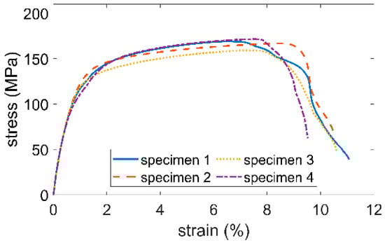
Figure 7.
Results of the tensile tests on four samples from the recycled semi-finished product made of EN-AW-6060 extruded at a speed of 6 rpm and the reference specimen.
Table 2.
Mechanical properties of the recycled wires and the average value of the reference specimen in comparison.
Even in a comparative analysis of the material properties of the conventionally produced wire determined in the tensile test, a direct comparison is only possible if a comparable delivery condition is considered. For the tensile tests on the reference wire, therefore, the solution-annealed wire made of EN-AW-6060 with a diameter of 4 mm is also used. The 0.2% proof stress of the reference sample is determined at 81 MPa, and the tensile strength is determined at 148 MPa. The analysis of these two mechanical properties also shows that, assuming both wires are in the same delivery condition, the wires produced by the friction-induced recycling process have a higher strength. The 0.2% proof stress of the recycled wires is on average about 40% higher than that of the conventionally extruded wire. The tensile strength is around 11% higher.
4.4. Microstructure
In addition to a comparison of the mechanical and optical properties, the microstructure of the cross-section of the reference wire is compared with the wire described in this work using two exemplary microsections. Figure 8a shows the grain structure of the reference wire, and Figure 8b shows the grain structure of the friction-induced recycled wire. Based on DIN EN ISO 643, an average grain size of 34 µm can be determined. The grain structure of the wire produced with the friction-induced extrusion process at a speed of 9 rpm shows a highly refined grain structure with an average grain size of 3 µm. This refined grain structure compared to the reference wire can therefore provide an explanation for the improved mechanical properties of the wire produced by the friction-induced recycling process.
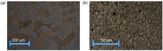
Figure 8.
Grain structure of (a) reference wire, (b) wire produced with the friction-induced recycling process.
A comparable effect on the microstructure and on the mechanical properties could be widely observed during the processing of tubular workpieces with the friction spinning. The results support the assumption of the authors that a separate examination of the plasticization of the chips via the above mentioned extrusion process is much more effective compared to direct part production using chips with the friction spinning process.
4.5. Energy Audit
Recycling, including material recycling, can and will make an important contribution to reducing global carbon emissions [14]. To determine the associated effects, it is essential to determine the amounts of energy used in the respective processes. The energetic consideration of the manufacturing process of aluminum represents a challenge due to a wide variety of influencing factors. In the production process of both primary and secondary aluminum, thermal energy, electrical energy, and fossil auxiliary materials are used as energy sources. In order to make a uniform and comparable energy assessment of the different forms of energy, it is necessary to express the forms of energy used in comparable energy units. However, no global determination of conversion factors is possible due, for example, to the different proportions of fossil fuels used to generate electrical energy. These difficulties in determining a uniform conversion factor from electrical energy to primary energy for aluminum production is the reason for the large amount of divergent and contradictory data on energy consumption. Another challenge in the preparation of a complete energy balance is the limitation of the balance area. This paper describes a process concept that can be implemented without high investment costs. The chips can be reprocessed into a continuous semi-finished product at the precise point in which they occur in the company. The possibility of decentralized and low-energy recycling represents one of the greatest advantages compared to the conventional production process. The expenses and energy consumption for transport processes in the primary and secondary manufacturing process do not have to be incurred. In an energy comparison of the processes, it must also be taken into account that such expenses as transport processes or further processing from a cast ingot are not taken into account in the energy balance in some cases [15].
Taking this into account, a small estimate of the respective energy consumption is attempted here for purposes of comparison. If half the energy required for aluminum production is obtained from hydroelectric and half from coal-fired power plants, 155.9 MJ is used to produce 1 kg of primary aluminum in ingot form [16].
Considering Schwarz, secondary aluminum production requires 17.7 MJ/kg [17]. Further energy expenditures for the production of semi-finished products and transport, etc., are not yet broken down in this calculation. The recycling process that works with the approach described in this paper can be performed in a decentralized manner without an increased effort to transport and collect the aluminum chips. For the production of one kilogram of aluminum wire (diameter of 5 mm and rotational speed of 6 rpm), the energy consumption is 2.41 kWh or 8.68 MJ. In order to be able to consider the three processes in a differentiated manner with regard to energy consumption, the corresponding research will be carried out at the LUF. It is possible to improve the output rate of the innovative recycling process by increasing the speed of the wheel. If this is possible while maintaining a good product quality, the energy requirement can be reduced even further.
5. Conclusions
This paper describes an innovative recycling approach to the production of user-specific semi-finished products. Analogous to related processes such as friction spinning, the heat required for a successful process flow can be friction-induced and achieved without the use of external heating elements. Based on the measurement results of the hardness curve over the entire workpiece surface, it can be concluded that the resulting products not only have a homogeneous cross-section but also a homogeneous distribution of mechanical properties. The mechanical properties are also constant over several test samples, as shown by the tensile tests. Compared to primary and also to secondary aluminum production, energy and effort can be saved by using the innovative process. Further investigations to improve the quality of the semi-finished products produced through heat treatments and through electrochemical pretreatments will be carried out in the future.
Author Contributions
Investigation, T.B.; methodology, T.B. and W.H.; writing—original draft preparation, T.B.; writing—review and editing, T.B. and W.H.; project administration and funding acquisition, T.B. and W.H. All authors have read and agreed to the published version of the manuscript.
Funding
This research was funded by Ministerium für Wirtschaft, Innovation, Digitalisierung und Energie des Landes Nordrhein-Westfalen and by the Ministerium für Kultur und Wissenschaft des Landes Nordrhein-Westfalen within the scope of the NRW Forschungskolleg “Leicht–Effizient–Mobil”.
Institutional Review Board Statement
Not applicable.
Informed Consent Statement
Not applicable.
Data Availability Statement
The data presented in this study are available on request from the corresponding author.
Conflicts of Interest
The authors declare no conflict of interest.
References
- Lossen, B.; Homberg, W. Ressourceneffizienz am Beispiel des Reibdrückens. In Wissenschaft im Angesicht »großer gesellschaftlicher Herausforderungen«; Riegraf, B., Berscheid, A.-L., Eds.; transcript Verlag: Bielefeld, Germany, 2018; pp. 159–178. [Google Scholar]
- Tekkaya, A.E.; Schikorra, M.; Becker, D.; Biermann, D.; Hammer, N.; Pantke, K. Hot profile extrusion of AA-6060 aluminum chips. J. Mater. Process. Technol. 2009, 209, 3343–3350. [Google Scholar] [CrossRef]
- Lossen, B.; Homberg, W. Friction spinning—Twist phenomena and the capability of influencing them. AIP Conf. Proc. 2016, 1769, 70001. [Google Scholar] [CrossRef]
- Haase, M.; Ben Khalifa, N.; Tekkaya, A.E.; Misiolek, W.Z. Improving mechanical properties of chip-based aluminum extrudates by integrated extrusion and equal channel angular pressing (iECAP). Mater. Sci. Eng. A 2012, 539, 194–204. [Google Scholar] [CrossRef]
- Haase, M.; Tekkaya, A.E. Recycling of Aluminum Chips by Hot Extrusion with Subsequent Cold Extrusion. Proc. Eng. 2014, 81, 652–657. [Google Scholar] [CrossRef]
- Buffa, G.; Campanella, D.; Fratini, L.; Micari, F. AZ31 magnesium alloy recycling through friction stir extrusion process. Int. J. Mater. Form. 2016, 9, 613–618. [Google Scholar] [CrossRef]
- Etherington, C. Conform—A New Concept for the Continuous Extrusion Forming of Metals. J. Eng. Ind. 1974, 893–900. [Google Scholar] [CrossRef]
- Pardoe, J.A. Conform continuous extrusion process—Its contribution to energy conservation. Met. Technol. 1984, 11, 358–365. [Google Scholar] [CrossRef]
- Pardoe, J.A. ‘Conform’ Continuous Extrusion of Metal Powders into Products for Electrical Industry: Development Experience, Metallurgy. Powder Metall. 1979, 22, 22–28. [Google Scholar] [CrossRef]
- Thomas, B.M.; Derguti, F.; Jackson, M. Continuous extrusion of a commercially pure titanium powder via the Conform process. Mater. Sci. Tech. Ser. 2017, 33, 899–903. [Google Scholar] [CrossRef]
- Smythe, S.A.; Thomas, B.M.; Jackson, M. Recycling of Titanium Alloy Powders and Swarf through Continuous Extrusion (ConformTM) into affordable Wire for Additive Manufacturing. Metals 2020, 10, 843. [Google Scholar] [CrossRef]
- Güley, V.; Ben Khalifa, N.; Tekkaya, A.E. The Effect of Extrusion Ratio and Material Flow on the Mechanical Properties of Aluminum Profiles Solid State Recycled from 6060 Aluminum Alloy Chips. AIP Conf. Proc. 2011, 1353, 1609–1614. [Google Scholar] [CrossRef]
- DIN EN ISO 6507-1:2018-07. Available online: https://www.beuth.de/en/standard/din-en-iso-6507-1/280959455 (accessed on 23 February 2021).
- Cooper, D.; Allwood, J. Reusing Steel and Aluminum Components at End of Product Life. Environ. Sci. Technol. 2012, 46, 10334–10340. [Google Scholar] [CrossRef] [PubMed]
- Moya, J.A.; Boulamati, A.; Slingerland, S.; van der Veen, R.; Gancheva, M.; Rademaekers, K.M.; Kuenen, J.J.P.; Visschedijk, A.J.H. Energy Efficiency and GHG Emissions: Prospective Scenarios for the Aluminium Industry; Report EUR 27335 EN; Publication Office of the European Union: Luxembourg, 2015. [Google Scholar]
- Balomenos, E.; Panias, D.; Paspaliaris, I. Energy and exergy analysis of the primary aluminum production processes: A review on current and future sustainability. Min. Proc. Ext. Met. Rev. 2011, 32, 69–89. [Google Scholar] [CrossRef]
- Schwarz, H.G. Aluminum Production and Energy. Encycl. Energy 2004, 1, 81–95. [Google Scholar]


Publisher’s Note: MDPI stays neutral with regard to jurisdictional claims in published maps and institutional affiliations. |
© 2021 by the authors. Licensee MDPI, Basel, Switzerland. This article is an open access article distributed under the terms and conditions of the Creative Commons Attribution (CC BY) license (https://creativecommons.org/licenses/by/4.0/).