
Investigation of Punch Shape and Loading Path Design in Hydro-Flanging Processes of Aluminum Alloy Tubes

Abstract
1. Introduction
2. Finite Element Modelling
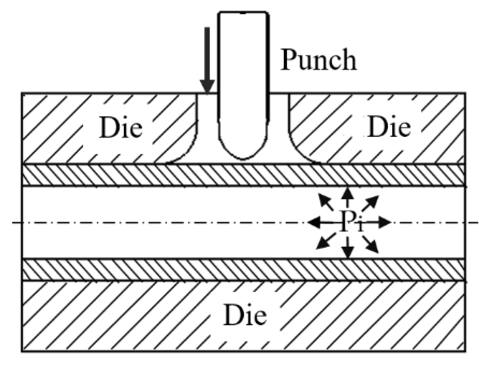
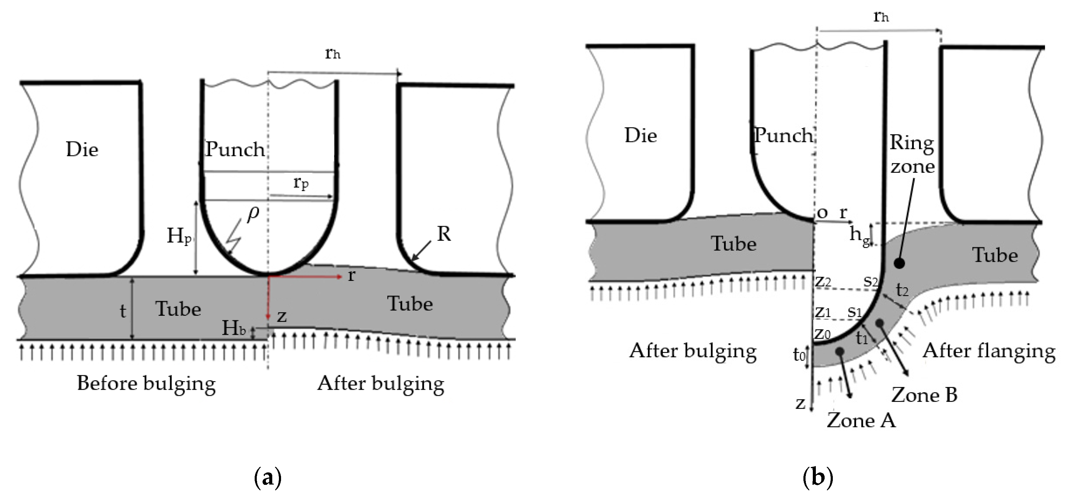
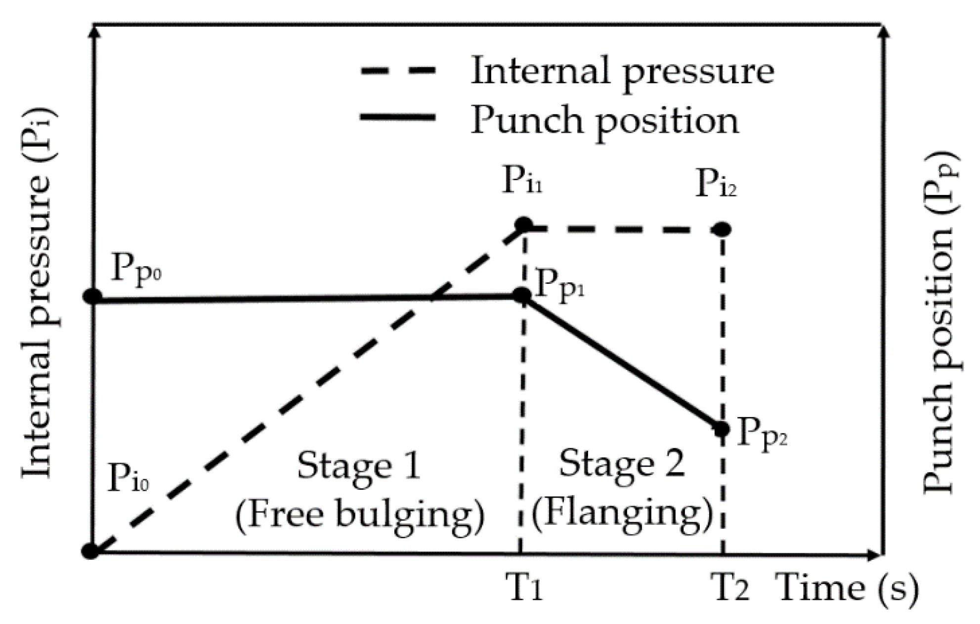
2.1. Geometric Configurations during Hydro-Flanging
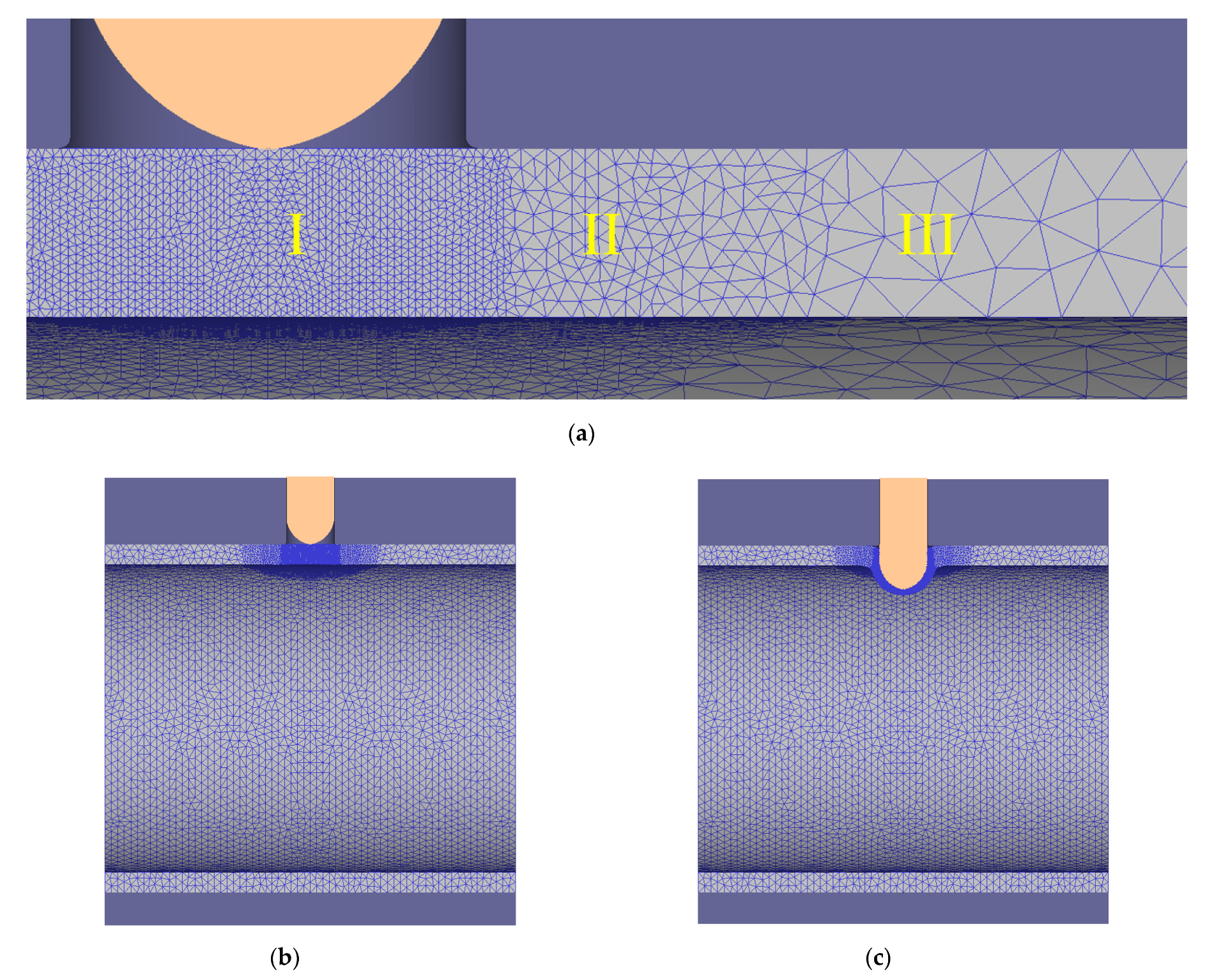
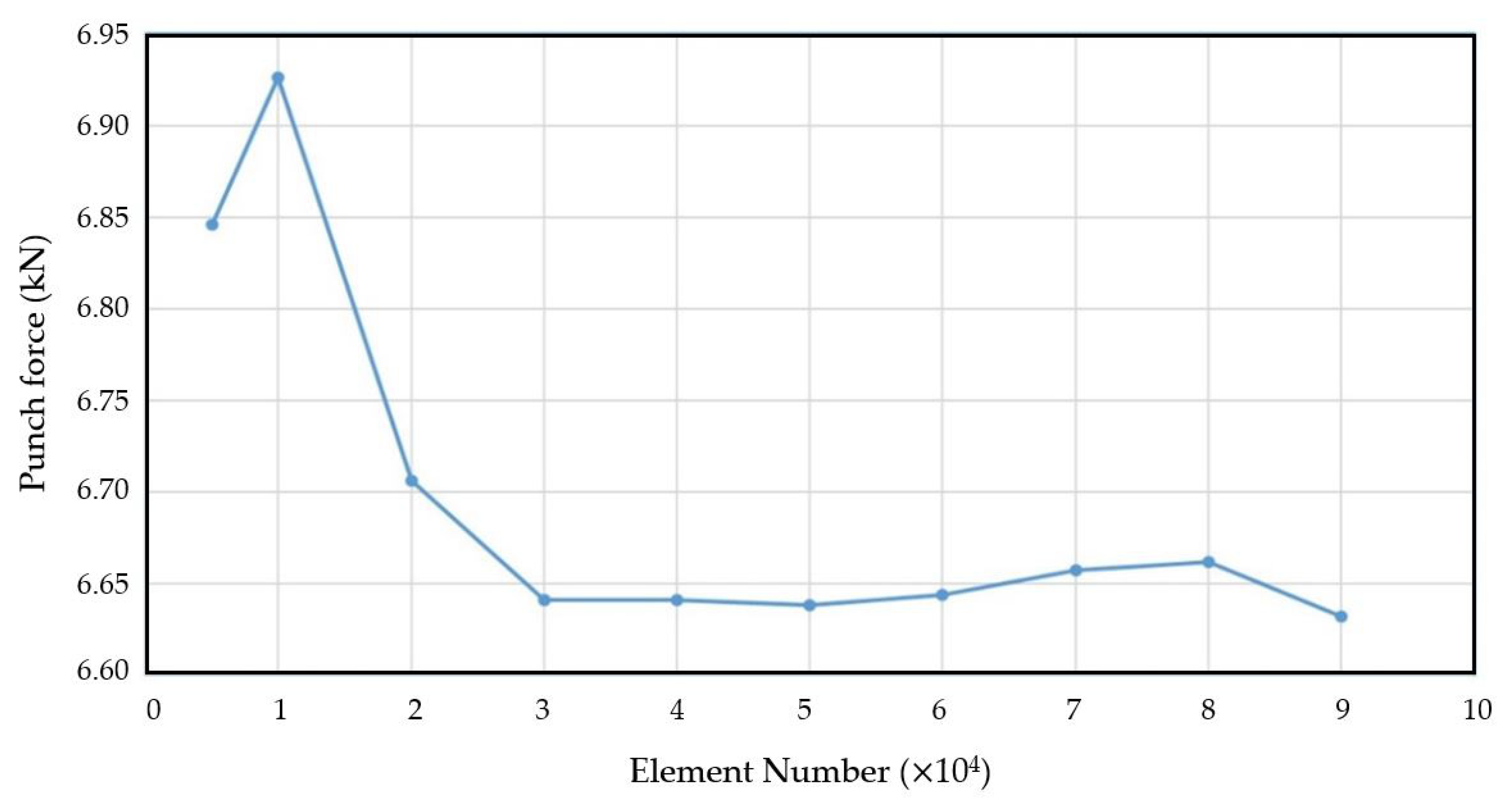
2.2. Finite Element Simulations in Hydro-Flanging
3. Simulation Results and Discussion
3.1. Thickness Distributions at Flanging Region
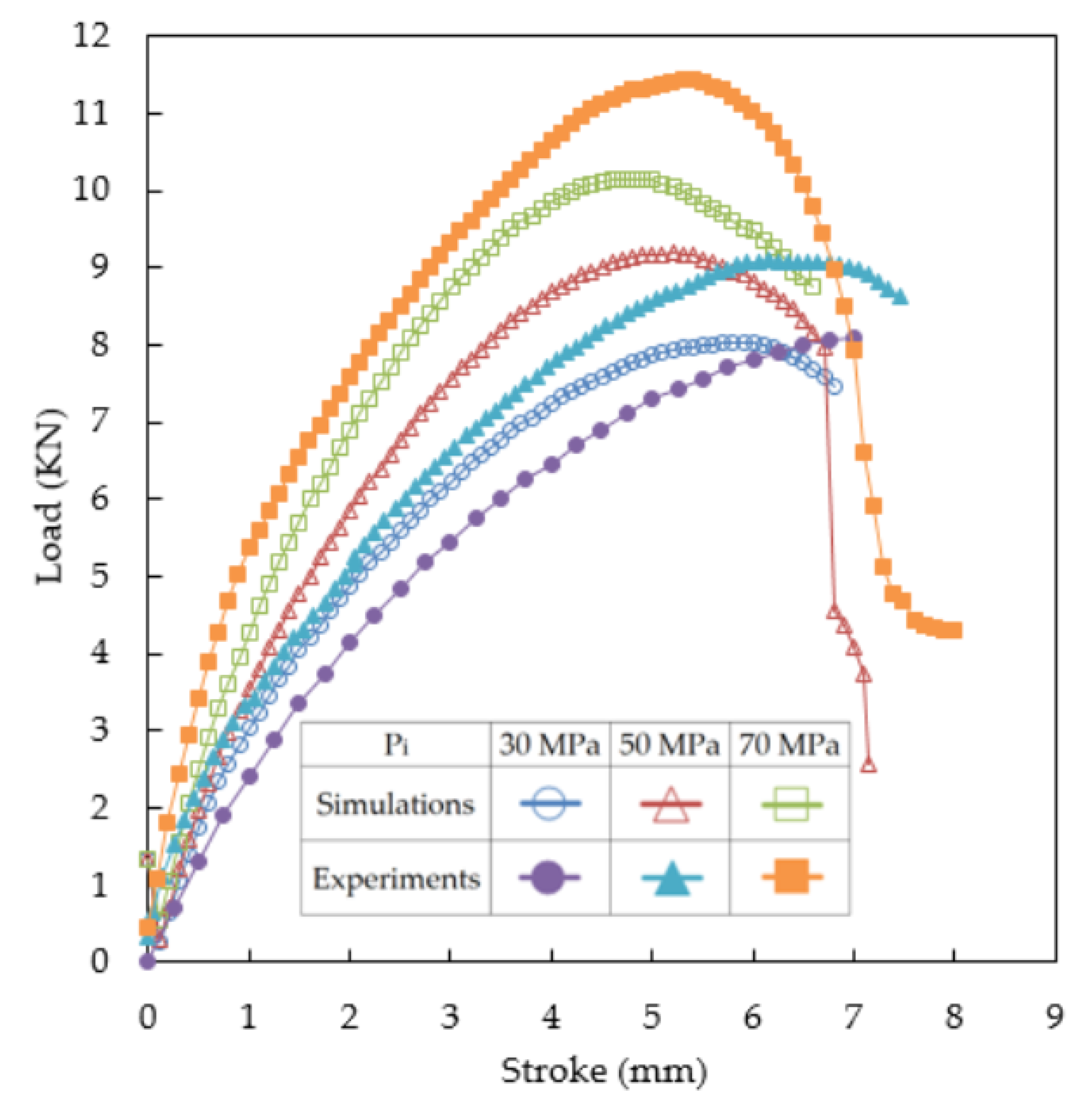
3.2. Punch Load Variations
4. Experiments of Hydro-Flanging of Aluminum Alloy Tubes
4.1. Experimental Results of Hydro-Flanging Processes
4.2. Comparisons of Simulative and Experimental Results
5. Conclusions
- (1)
- As the internal pressure increased, the thickness of the tube at the bottom of the punch head became thinner. At a higher internal pressure, the tube was bulged up and, hence, the thickness close to the ring zone became thicker and that under the punch head became thinner.
- (2)
- A short blunt punch head made the thickness distribution more uniform and the thickness t2/t0 ratio was close to unity, which was more likely to result in fracture in zone B. If a long punch head was used instead, t2/t0 became larger, fracture would probably occur at zone A at the bottom of the punch head.
- (3)
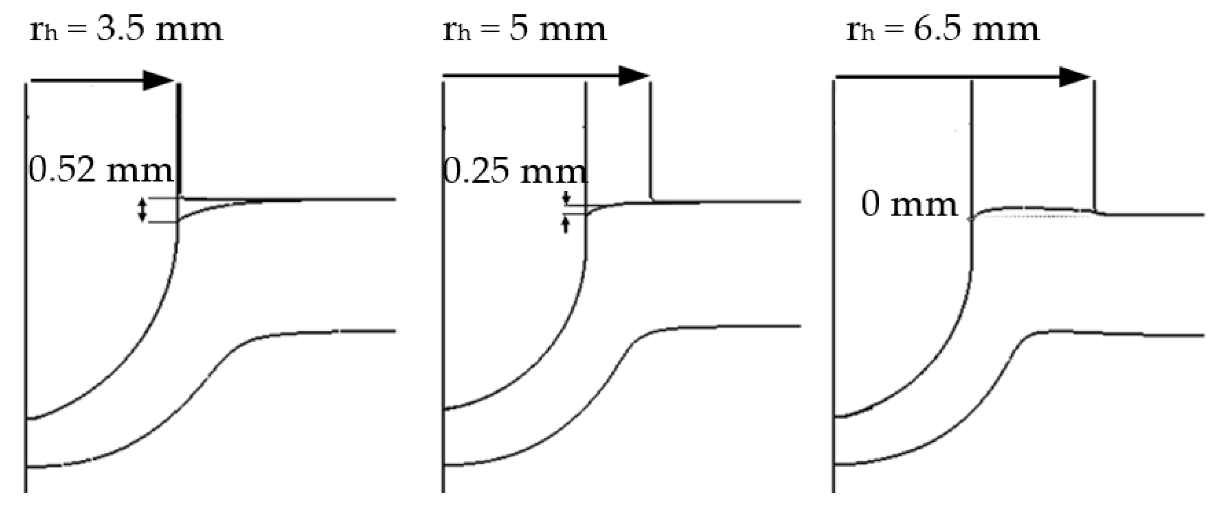
- The change of punch hole radius rh at a lower pressure did not affect the thicknesses at the flanging region; however, at a higher pressure of 70 MPa, the thicknesses decreased obviously as rh increased.
- (4)
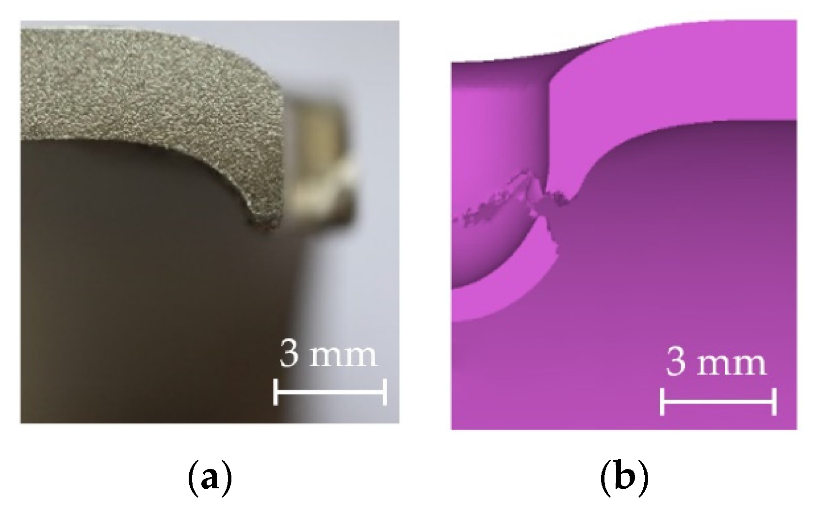
- The simulation results of thickness distributions and maximum punch loads were generally the same as the experimental results. Under a high internal pressure and a short blunt punch head, fracture was more likely to occur in zone B.
Author Contributions
Funding
Institutional Review Board Statement
Informed Consent Statement
Data Availability Statement
Acknowledgments
Conflicts of Interest
References
- Dohmann, F.; Hartl, C. Tube hydroforming—Research and practical application. J. Mater. Process. Technol. 1997, 71, 174. [Google Scholar] [CrossRef]
- Ahmetoglu, M.; Altan, T. Tube hydroforming: State-of-the-art and future trends. J. Mater. Process. Technol. 2000, 98, 25. [Google Scholar] [CrossRef]
- Fracz, W.; Stachowicz, F.; Trzepiecinski, T. Investigations of thickness distribution in hole expanding of thin steel sheets. Arch. Civ. Mech. Eng. 2012, 12, 279–283. [Google Scholar] [CrossRef]
- Kacem, A.; Krichen, A.; Manach, P.Y.; Thuillier, S.; Yoon, J.W. Failure prediction in the hole-flanging process of aluminum alloys. Eng. Fract. Mech. 2013, 99, 261–265. [Google Scholar] [CrossRef]
- Liu, W.; Hao, J.; Liu, G.; Gao, G.; Yuan, S. Influence of punch shape on geometrical profile and quality of hole piercing-flanging under high pressure. Int. J. Adv. Manuf. Technol. 2016, 86, 1253–1262. [Google Scholar] [CrossRef]
- Thipprakmas, S.; Jin, M.; Murakawa, M. Study on flanged shapes in fineblanked-hole flanging process using finite element method. J. Mater. Process. Technol. 2007, 193, 128–133. [Google Scholar] [CrossRef]
- Mizumura, M.; Sato, K.; Kuriyama, Y. Development of nut-inlaying technique in hydroformed component by hydro-burring. Mater. Trans. 2012, 53, 801–806. [Google Scholar] [CrossRef]
- Mizumura, M.; Sato, K.; Suehiro, M. Development of new hydroforming methods. Nippon Steel Tech. Rep. 2013. Available online: https://www.nipponsteel.com/en/tech/report/nsc/pdf/103-07.pdf (accessed on 15 March 2021).
- Choi, S.K.; Kim, W.T.; Moon, Y.H. Analysis of deformation surrounding a hole produced by tube hydro-piercing. J. Eng. Manuf. 2004, 218, 1091–1097. [Google Scholar] [CrossRef]
- Hwang, Y.M.; Wu, R.K. Process and loading path design for hydraulic compound forming of rectangular tubes. Int. J. Adv. Manuf. Technol. 2017, 91, 2135–2142. [Google Scholar] [CrossRef]
- Hwang, Y.M.; Dai, W.H.; Chen, C.C. Investigation of punch shape design in tube hydro-piercing processes. Int. J. Adv. Manuf. Technol. 2020, 110, 2211–2220. [Google Scholar] [CrossRef]
- Hwang, Y.M.; Tsai, Y.J. Movable die and loading path design in tube hydroforming of irregular bellows. Metals 2020, 10, 1518. [Google Scholar] [CrossRef]
- Park, J.Y.; Han, S.W.; Jeong, H.S.; Cho, J.R.; Moon, Y.H. Advanced sealing system to prevent leakage in hydroforming. J. Mater. Process. Tech. 2017, 247, 103–110. [Google Scholar] [CrossRef]
- Yu, X.Y.; Chen, J.; Chen, J.S. Interaction Effect of Cracks and Anisotropic Influence on Degradation of Edge Stretchability in Hole-expansion of Advanced High Strength Steel. Int. J. Mech. Sci. 2016, 105, 348–359. [Google Scholar] [CrossRef]
- Kumar, S.; Ahmed, M.; Panthi, S.K. Effect of Punch Profile on Deformation Behaviour of AA5052 Sheet in Stretch Flanging Process. Arch. Civil Mech. Eng. 2020, 20, 1–17. [Google Scholar] [CrossRef]
- Dixit, U.S.; Joshi, S.N.; Davim, J.P. Incorporation of material behavior in modeling of metal forming and machining processes: A review. Mater. Des. 2011, 32, 3655–3670. [Google Scholar] [CrossRef]
- Del Pozo, D.; López de Lacalle, L.N.; López, J.M.; Hernández, A. Prediction of press/die deformation for an accurate manufacturing of drawing dies. Int. J. Adv. Manuf. Technol. 2008, 37, 649–656. [Google Scholar] [CrossRef]
- Fernández-Abia, A.I.; Barreiro, J.; López de Lacalle, L.N.; Martínez-Pellitero, S. Behavior of austenitic stainless steels at high speed turning using specific force coefficients. Int. J. Adv. Manuf. Technol. 2012, 62, 505–515. [Google Scholar] [CrossRef]
- Hwang, Y.M.; Pham, H.N. Study of Hydro-Reaming and Flanging of Aluminum Tubes. Tube Hydroforming Technology. In Proceedings of the 9th International Conference on Tube Hydroforming, Kaohsiung, Taiwan, 18–21 November 2019; pp. 124–129. [Google Scholar]
- ASTM. Standard Test Methods for Tension Testing of Metallic Materials; E8/E8M-15; ASTM International: West Conshohocken, PA, USA, 2015; pp. 10–11. [Google Scholar]
- Oh, S.I.; Chen, C.C.; Kobayashi, S. Ductile fracture in axisymmetric extrusion and drawing. ASME J. Eng. Ind. 1979, 101, 36–44. [Google Scholar] [CrossRef]


| Object | Dimension or Property |
|---|---|
| Tube material | A6063-T0 (Elasto-plastic) |
| Tube outer diameter d0 (mm) | 50.8 |
| Tube initial thickness t (mm) | 3 |
| Punch material | Rigid |
| Punch radius rp (mm) | 3.45 |
| Punch head height Hp (mm) | 4.5 |
| Die material | Rigid |
| Die inner diameter (mm) | 50.8 |
| Die hole radius rh (mm) | 3.5 |
| Internal pressure Pi (MPa) | 50 |
| Temperature (°C) | 25 |
| Punch Height (Hp) | Internal Pressure (Pi) | t2 (Z2 = 2.5 mm) | t1 (Z1 = 3.75 mm) | t0 (Z0 = 5 mm) | t2/t0 |
|---|---|---|---|---|---|
| 4 mm | 30 MPa | 1.918 | 1.750 | 1.549 | 1.238 |
| 50 MPa | 1.686 | 1.627 | 1.420 | 1.187 | |
| 70 MPa | 1.523 | 1.608 | 1.456 | 1.046 | |
| 4.5 mm | 30 MPa | 2.076 | 1.664 | 1.206 | 1.721 |
| 50 MPa | 1.842 | 1.600 | 1.100 | 1.675 | |
| 70 MPa | 1.760 | 1.563 | 1.031 | 1.707 | |
| 5 mm | 30 MPa | 2.117 | 1.669 | 0.990 | 2.138 |
| 50 MPa | 1.932 | 1.597 | 0.876 | 2.205 | |
| 70 MPa | 1.846 | 1.545 | 0.810 | 2.279 |
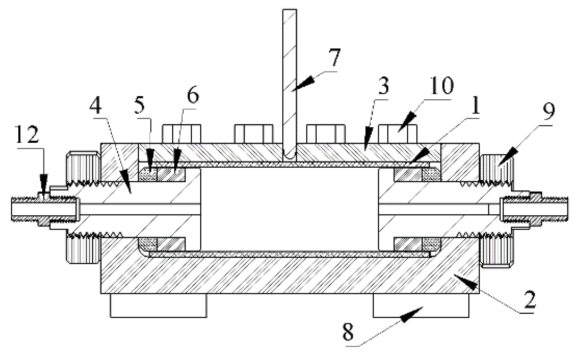
| No. | Component | No. | Component |
|---|---|---|---|
| 1 | Aluminum tube | 7 | Punch |
| 2 | Lower Die | 8 | Positioning pin |
| 3 | Upper Die | 9 | Nut (M30) |
| 4 | Mandrel | 10 | Screw (M12) |
| 5 | Steel ring | 11 | Screw (M6) |
| 6 | Rubber ring | 12 | Hose connector |
| Forming Conditions | Product Appearance | Cross-Sectional Appearance |
|---|---|---|
| Case 1 Pi = 0 MPa Stroke = 15.6 mm |  |  |
| Case 2 Pi = 30 MPa Stroke = 7 mm |  |  |
| Case 3 Pi = 50 MPa Stroke = 7 mm |  |  |
| Case 4 Pi = 50 MPa Stroke = 8 mm |  |  |
| Case 5 Pi = 70 MPa Stroke = 8 mm |  |  |
| Hp = 4 mm | Simulation | Experiment | Difference | ||||
|---|---|---|---|---|---|---|---|
| rh | Z | 30 MPa | 50 MPa | 30 MPa | 50 MPa | 30 MPa | 50 MPa |
| 3.5 mm | t2 (z2 = 2.5 mm) | 1.65 | 1.22 | 1.79 | 1.58 | −7.82% | −22.7% |
| t1 (z1 = 3.75 mm) | 1.43 | 1.27 | 1.51 | 1.41 | −5.29% | −9.93% | |
| t0 (z0 = 5 mm) | 1.13 | 1.12 | 1.26 | 1.20 | −10.3% | −6.67% | |
| t2/t0 | 1.46 | 1.089 | 1.421 | 1.345 | 2.74% | −19.0% | |
Publisher’s Note: MDPI stays neutral with regard to jurisdictional claims in published maps and institutional affiliations. |
© 2021 by the authors. Licensee MDPI, Basel, Switzerland. This article is an open access article distributed under the terms and conditions of the Creative Commons Attribution (CC BY) license (https://creativecommons.org/licenses/by/4.0/).
Share and Cite
Hwang, Y.-M.; Pham, H.-N.; Tsui, H.-S.R. Investigation of Punch Shape and Loading Path Design in Hydro-Flanging Processes of Aluminum Alloy Tubes. Metals 2021, 11, 636. https://doi.org/10.3390/met11040636
Hwang Y-M, Pham H-N, Tsui H-SR. Investigation of Punch Shape and Loading Path Design in Hydro-Flanging Processes of Aluminum Alloy Tubes. Metals. 2021; 11(4):636. https://doi.org/10.3390/met11040636
Chicago/Turabian StyleHwang, Yeong-Maw, Hong-Nhan Pham, and Hiu-Shan Rachel Tsui. 2021. "Investigation of Punch Shape and Loading Path Design in Hydro-Flanging Processes of Aluminum Alloy Tubes" Metals 11, no. 4: 636. https://doi.org/10.3390/met11040636
APA StyleHwang, Y.-M., Pham, H.-N., & Tsui, H.-S. R. (2021). Investigation of Punch Shape and Loading Path Design in Hydro-Flanging Processes of Aluminum Alloy Tubes. Metals, 11(4), 636. https://doi.org/10.3390/met11040636