Article

An All-Atom Simulation Study of Gas Detonation Forming Technique

by
Ambarish Kulkarni
1,
Vispi Karkaria
2,
Milankumar Nandgaonkar
2,
Sandeep P. Patil
1,2,* and
Bernd Markert
1
1
Institute of General Mechanics, RWTH Aachen University, Eilfschornsteinstraße 18, 52062 Aachen, Germany
2
Department of Mechanical Engineering, College of Engineering Pune, Wellesely Road, Shivajinagar, Maharashtra, Pune 411005, India
*
Author to whom correspondence should be addressed.
Metals 2021, 11(4), 611; https://doi.org/10.3390/met11040611
Submission received: 19 February 2021 / Revised: 4 April 2021 / Accepted: 6 April 2021 / Published: 9 April 2021

Abstract

:
The high-speed forming process is the key to attaining difficult and irregular profiles on ductile materials. In the present work, we proposed the all-atom model of the gas detonation forming process, wherein molecular dynamics (MD) simulations were performed on the aluminum workpiece at different loading speeds similar to the various pressure values in the process. The deformation response of an aluminum workpiece for a wide range of loading speeds, 0.1–8 Å/ps, was investigated. The dome-height, failure patterns, and formability of the aluminum workpiece were examined for these loading speeds. We obtained an inverse relationship between the formability of the aluminum workpiece and the applied loading speed. Moreover, in this work, the influence of the different percentage of defects in the workpieces on the mechanical behavior was investigated. We observed that at lower speeds (< 2 Å/ps), the deformation is observed throughout the workpiece starting from the point of contact in the middle and that is contrary to the deformations observed due to the higher loading speed where localized deformations occur due to creation of slipping planes. We also found that the internal voids lead to the rearrangement of atoms to facilitate the movement of slipping planes leading to better formability compared to the no-void workpieces. This work helps to get a fundamental understanding of deformation behavior in the high-speed forming process with and without defects in the aluminum workpiece at the nanoscale.

1. Introduction

Gas detonation is a process in which gases like oxygen and hydrogen are detonated. The detonation creates pressure energy as a shockwave essential for performing the high-speed forming [1]. The forming process is faster if incorporated with gas detonation as compared to other forming processes [2]. Gas detonation is definitely a safer alternative to solid detonation, enabling the manufacturing of complex geometric shapes with superior accuracy. The manufacturing costs are also lower for gas detonation forming compared to other forming processes [3]. Experimental studies using hot metal gas forming have been performed for studying different methodologies of the gas detonation process itself and its effects on material properties, such as hardness and microstructure of metals [4,5,6].
Molecular dynamics (MD) can be defined as a simulation method used to analyze the physical speed and moment of the atoms and molecules at the nanoscale. It is a computer simulation method to solve Newton’s equations of motion numerically for the atoms in the system. It enables the study of the time evolution of coordinates and speed of each atom with high time and space resolution [7]. MD simulations have been used to investigate the high-speed cutting processes at the atomic level [8,9]. For such processes, MD simulation is a better tool as compared to finite element analysis (FEA) as it can analyze at the nanoscale, with no need for constitutive laws and no imperial parameters required. Another advantage that MD simulation has over FEA is that it can analyze very low time ranges, that is, in femtoseconds [10]. FEA needs considerably higher resources for dynamic processes, even at microsecond levels. MD simulation is changing into a powerful tool in the last three decades as previously only small models were modeled. But now, MD is capable of simulating larger models with millions of atoms [11,12,13]. Recently, MD simulations have been used in many areas, such as a high-speed stretching process [14] and pulse laser simulations [15]. Moreover, forming operations with ion-bombarding aid can be simulated using MD simulations [16,17].
MD simulations can be effectively used to simulate machining lattice vibrations [18] and the plastic deformation process forces acting in the nanoscale [19,20]. MD makes it possible to study the intermolecular forces, which helps to find the exact 3D shape of the model [21]. Analyzing high-speed forming with the aid of MD helps to determine the change in grain and molecule size before and after forming processes [22]. Studying the effect of the high-speed forming process with respect to temperature and thermal changes [23], assessing the material lost during nanoindentation is easily possible [24]. High-speed forming processes like nano-printing can also be precisely modeled by MD simulations [25]. Moreover, MD simulations enable the analysis of frictional forces at play [26]. Real-time movements of all the atoms in the system can also be detected in an MD simulation [27]. Furthermore, wrinkles and scratches which can arise due to forming can also be produced in the nanoscale with the aid of MD simulations [28].
There have been several interesting MD simulation studies on high-speed processes, such as grinding, abrasion and cutting, in the literature. These studies have shed light on the deformation of materials on a nanoscale. Yamakov et al., made a strong case for the use of MD simulations through their study on dislocation processes in the deformation of nanocrystalline aluminum. They showed that MD simulations have now advanced to a level where it provides a powerful new tool for elucidating and quantifying—in a degree of detail not possible experimentally—the atomic-level mechanisms controlling the complex dislocation and grain-boundary processes in heavily deformed materials with a submicrometre grain size [29]. Rentsch et al. studied the abrasive machining processes through an MD perspective. Their work particularly focused on the differences and necessities in contrast to the simulation of cutting processes with regards to the pile-up phenomenon in abrasive machining [30]. Shimizu et al., verified using MD simulations that the plastic deformation is reduced when the machining speed exceeds the material static propagation speed of the plastic wave, and its mechanism is completely different from that of the ordinary grinding process [31]. Ye et al. found insights about the underlying nanometric cutting process of single crystal copper for a nanoscale machining process through MD simulations [9]. Zhang et al. also studied monocrystalline copper for a nanometric cutting process using MD simulations and found out details of subsurface deformations [32]. Ren et al. effectively used MD simulations to calculate various aspects of a fast-paced grinding operation and obtained a better understanding of the chip formation mechanism in the grinding process [33]. Moreover, Patil and Heider have presented high-speed crack propagation in different materials using MD simulations [34].
The drawing process is a type of high-speed forming process in which we study the effects of deformation like change in dimensions, time taken for operation, punch force, holding force, and operating temperature. One point to be noted here is the fact that all these analyses have been done using FEA and not using MD [35]. Conducting FEA makes it difficult to study the forming process in detail, for example, molecular origin of failure or fracture [36]. MD also helps us to accurately find out the start of crack propagation in a high-speed forming or drawing process [37]. Deformation at the molecular level and indicating a crack’s propagation in the drawing process is difficult to analyze on the macroscopic level [38]. We investigated the gas detonation forming process using FEA in our previous works. Using the Johnson-Cook material model, we studied the forming process for DC-04 steel [1]. We realized that gas detonation forming has a capacity for a novel application. Our research on the topic resulted in a new technique for joining tubes enabled by gas detonation [39]. To understand the effects of the process on the workpieces on a deeper level, we experimented in conjunction with a simulation study on the material damage [40]. Moreover, we investigated the response of stacked workpiece plates of different metals to shockwave loading. We carried out experiments at our shockwave lab and simultaneously simulated the process using FEA [41]. Furthermore, we used a Rapid Compression Machine (RCM) for the high-speed forming of the aluminum alloy samples. We compared the outcomes of numerical simulations that replicated the conditions of the RCM. We found great agreement in the results of simulations and experiments [42].
From the literature, it is abundantly clear that MD simulations have noticeable advantages in the high-speed forming research area. Despite this, the current research body lacks observations and inferences from the MD simulation perspective, especially for the gas detonation forming process. Therefore, this work is an extension of our previous work on gas detonation forming. This paper is an attempt to shed some light on the aspects of the high-speed forming process that are observed through MD simulations.
This paper is organized as follows—in Section 2, we have discussed the methods and materials that comprise this work. In Section 3, we have discussed the significant results obtained from MD simulations where we have highlighted the topics such as progression of deformation of the workpiece at different constant load speeds, the relationship between the dome-height and load speeds, failure patterns of the workpiece under different conditions, and the influence of material flaws on the simulation. Finally, we have approached the end of this paper with conclusive remarks and comments on further research scope in Section 4.

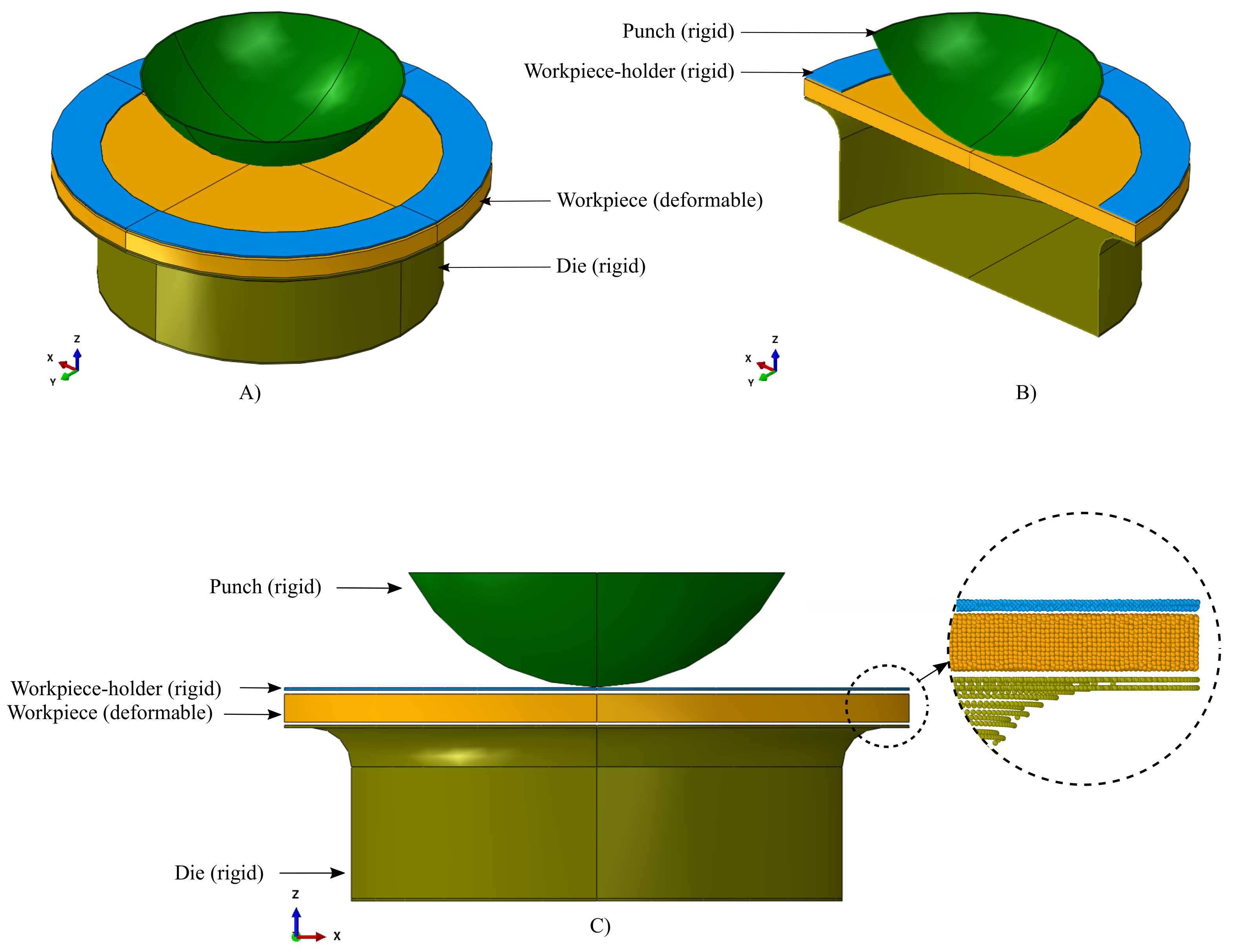
2. Methods and Materials

For this study, a Large-scale Atomic/Molecular Massively Parallel Simulator (LAMMPS) [43] was used for simulating the high-speed forming process on the aluminum workpiece, and the open visualization tool OVITO [44] was utilized to observe and create figures of various aspects in the post-processing of simulations.
Figure 1 shows schematic representation of MD simulation setup. The workpiece is a circular disc, which is placed between the die and the workpiece-holder. It is a deformable object made of aluminum. The workpiece-holder, punch and die are modeled of carbon-diamond. The punch is above the workpiece and tangentially touches the workpiece at one point, that is, at the center of the workpiece. All three bodies made of carbon-diamond are assumed to be perfectly rigid, that is, relative positions between the atoms of these three bodies are not changed during the course of the simulations. This also means that these bodies are non-deformable, contrary to the deformable workpiece. For the carbon atoms, the Tersoff interatomic potential was used [45,46].
The energy of the system is minimized using the steepest descent algorithm. Even though computationally a little more expensive, the steepest descent algorithm is more robust and stable for the complex MD systems than the conjugate gradient algorithm [43]. Given the highly dynamic nature of the simulation, the NVT (constant number of atoms, volume, and temperature) and NPT (constant number of atoms, pressure, and temperature) ensembles have been employed for the equilibration of the system energy of the simulation. All the simulations were carried out at atmospheric conditions (300 K and 1 bar).
In this work, modeling the workpiece and the workpiece-holder was done with combinations of Boolean operations through LAMMPS commands. Modeling of the die and the punch was done by using Abaqus CAE [47]. Both these parts, the die and the punch, were meshed using 8-noded brick elements with a mesh density adequate enough not to allow any penetration of the workpiece during the simulation. The nodal coordinate data of the mesh was used to represent the positions of the atoms. As the die and the punch are also considered rigid bodies, there were no repulsive or attractive forces between their atoms that have to be considered. Therefore, the crystal lattice structure of those bodies was not considered according to any of the standard crystal structures; rather, the nodal data obtained from the FE modeling was used. We have employed this novel approach only to model complicated geometries, which are considered rigid bodies. The punch is modeled as a portion from the bottom half of a sphere in order to mimic the experimental pressure profile conditions. Therefore, we applied the loading pattern in such a way that it is maximum at the center and, as the load progresses, it transfers to the radial directions.
The major dimensions of the setup are as follows. The workpiece disc is 900 Å in diameter and 40.5 Å in thickness. The internal diameter of the die is 700 Å, and the internal depth of the die is 250 Å from its top surface. The rounded top edge on the top side of the die has a diameter of 120 Å. The curved profile of the punch has a diameter of 610 Å. The workpiece holder (shaped like an annular disc) has an internal diameter of 700 Å, and an external diameter of 900 Å. A gap of 5.5 Å is maintained between the workpiece-holder and the workpiece, whereas a gap of 4.5 Å is maintained between the workpiece and the die. The separation between the punch and the workpiece is 10 Å. All the parts are coaxial and aligned to the z-axis of the global coordinate system, as shown in the schematic setup.

2.1. Interatomic Potentials

For describing the metallic bonding characteristics better than the two-body potentials, the embedded atom model (EAM) potentials were developed [48,49,50]. Measuring the realistic effect of free electron gas that surrounds every atom, a logical furthering of the two-body potentials for metals is done in the EAM potentials. Thus, it is considered that these potentials can realistically model the changes in metal properties close to a free surface based on potential energy functions.
The EAM considers pair interactions ϕ ( r i j ). They are included between the atoms i and j along with the energies of individual atoms i. The EAM potential is expressed by effective electron density ρ in the point of location of an atom i with the function Φ ( ρ i ).
Hence,
U = i Φ ( ρ i ) + i < j ϕ ( r i j ) .
The effective electron density ρ is given by
ρ i = j ψ ( r i j ) ,
where r i j denotes a contribution to the electron density from an atom j. The functions Φ ( ρ i ) , ϕ ( r i j ) and ψ ( r i j ) are altered and set using the system’s experimental properties.
In this paper, the EAM potentials are used to simulate aluminum-aluminum pairs in the forming process.

2.2. Description of the Morse Potential

The Morse potential is a widely used empirical pairwise potential energy function [51]. This potential produces repulsive forces in the short-range, attractive forces in the medium range, and decays smoothly to zero in the long-range. It uses a form of potential containing two exponential terms. Lim [52] provides an in-depth exploration of the validity of this function for non-bonded interactions.
The Morse potential is given by
U = D 0 exp ( 2 α ( r i j r 0 ) ) 2 exp ( α ( r i j r 0 ) ) ,
where U denotes the pair potential energy function, D 0 represents the cohesion energy, α denotes a constant of Morse potential, r i j denotes the interatomic distance, and r 0 denotes the distance of equilibrium.
We have used the Morse potential function to model the atomic interactions for aluminum-carbon pair. For the aluminum-carbon interaction, the cohesion energy is 0.4691 eV, Morse potential constant, α is 1.738 Å 1 , and the distance of equilibrium is 2.246 Å.
The force acting on an individual atom was obtained by summing the forces contributed by the surrounding atoms. The EAM potentials address the interaction forces of aluminum atoms with other aluminum atoms. The Morse potentials address the forces of interactions between aluminum atoms and die, punch and workpiece-holders, that is, the interactions between the deformable workpiece and the rigid bodies.
The force on atom i resulting from the interaction of all the other atoms can be derived from the above potential functions U, such that
F i = j = 1 ( j i ) N i U ( r i j ) = m i d 2 r i ( t ) d t 2 ,
where F i is the resultant force on atom i, m i is the mass of an atom i, r i is the position of atom i, and N is the total number of atoms.

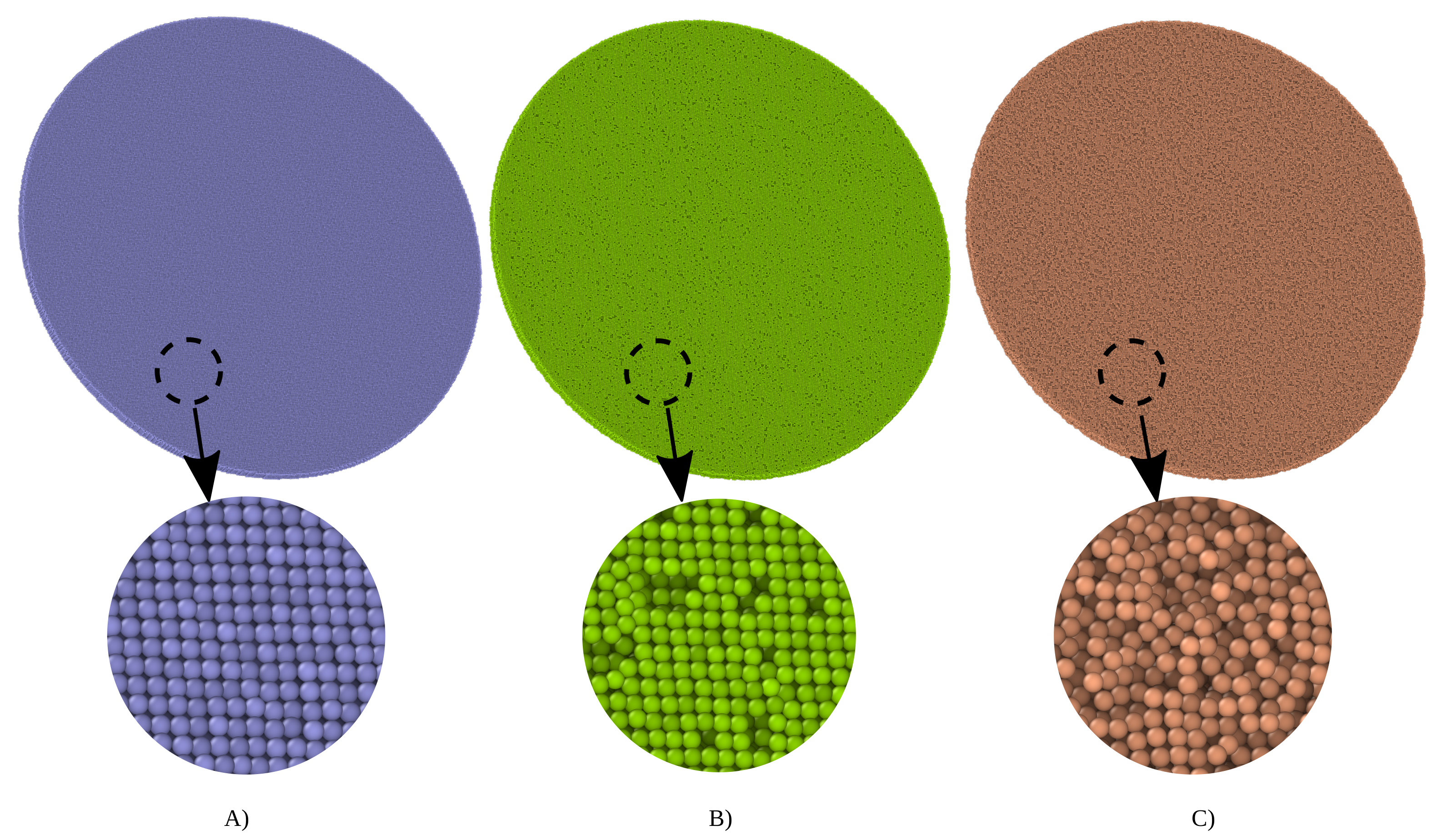
2.3. Voids in the Workpiece Models

To understand the influence of the internal material voids in the workpiece on the mechanical properties, we have modeled four different samples of the workpiece with 5, 10, 15 and 20% material flaws, wherein atoms were deleted randomly throughout the workpiece models using an iterative randomizer algorithm in LAMMPS [43]. Figure 2 depicts the comparison of the MD models without and with different percentages of flaws. The parts that would be acquired for testing may come from different manufacturers, and it is safe to assume that there would be voids in these parts. Moreover, the void distribution in the parts cannot be uniform. The voids present in the workpiece could be of any percentage. For the theoretical study, an ascending percentage of internal voids starting from 5% is considered. Uniform distribution of voids would mean artificial voids. Therefore, to avoid artificial voids, a random distribution of voids was chosen. Percentages of flaws can be interpolated from the considered and available flaw percentages, which are in a generally low range (up to 20%).
All the simulations were performed in a vacuum, wherein the boundaries of the simulation box were far away from the model. The die and the workpiece holder were fixed in their positions. The application of force on the workpiece in the axial direction through the punch was modeled by moving the punch with different constant velocities in the downward direction towards the workpiece (see z-direction in Figure 1).

3. Results and Discussion

Subjecting the aluminum workpiece to different constant loading speeds, that is, movement of the punch in the downward direction towards the workpiece results in different deformation behavior and, ultimately, the failure of the workpiece. The constant speeds of loading are as follows: 0.1, 0.4, 0.8, 1, 2, 4, 6, and 8 Å/ps. In the following subsections, the progression of workpiece deformation, dome-height versus loading speeds, failure patterns, and influence of material flaws on the deformation behavior are discussed.

3.1. Blanking of the Workpiece due to Cylindrical Punch

At the beginning of this work, we modeled the punch as a cylinder. The intention behind this was to represent a uniform distribution of pressure (created by the detonated gases resulting in a shockwave) on the workpiece through the bottom face of the cylindrical punch. Figure 3 shows the progress of Al workpiece deformation at low-speed (1 Å/ps) with a cylindrical punch. When the workpiece was subjected to deformation through a cylinder-shaped punch, as the punch progressed downward on the workpiece at a speed of 1 Å/ps, the atoms that came in contact with the punch started getting separated from the rest of the workpiece. The part of the workpiece under the cylindrical punch did not deform at all compared to the rest of the portion of the workpiece atoms. Therefore, a direct application of pressure on a circular profile leads to blanking of the workpiece. In other words, the cylindrical profile of pressure load on the workpiece leads to very high shear forces along the circumference (edges) of the cylinder as the workpiece-holder and the die assisted in the shearing phenomenon, and the workpiece was cut into a disc with a smaller radius. Because of the reasons mentioned above, we decided to use a portion of a hemisphere as the profile of the punch to mimic the experimental pressure profile, which is varying pressure with the highest amplitude in the center for the forming process.

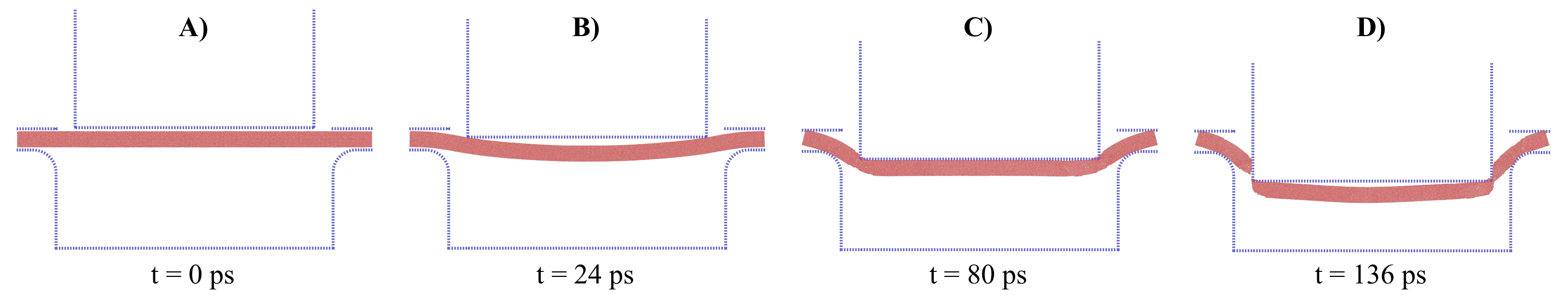
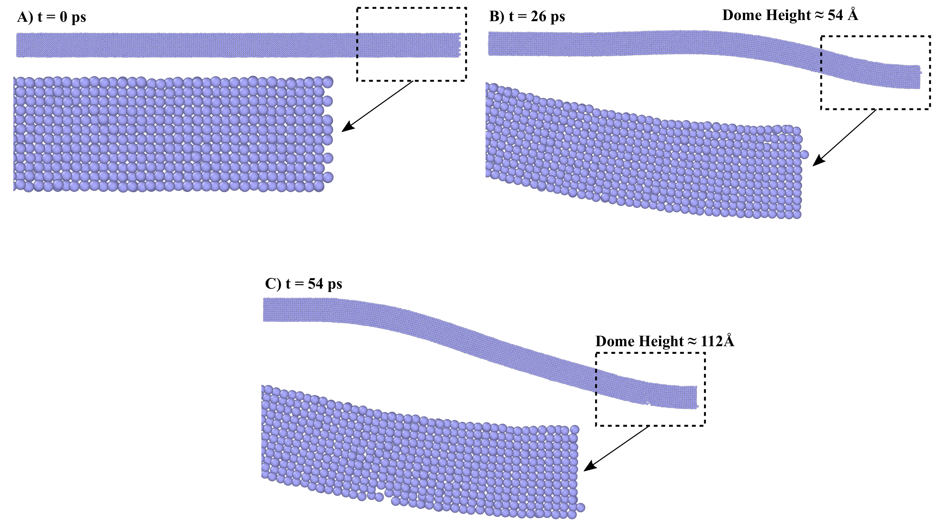
3.2. Progress in Workpiece Deformation

Figure 4 shows the snapshots of the workpiece (with no voids) deformation before the complete failure at different loading speeds. For the low loading speed simulations (0.1 Å/ps), the required simulation time to get maximum dome-height without failure was 1.18 ns (see Figure 4A). For medium (0.8 Å/ps) and high-speed (6 Å/ps) simulations, the required simulation times were 0.12 ns and 0.01 ns, respectively. Moreover, the formability of the aluminum workpiece was lower for higher speeds.
At lower speeds, the atoms get sufficient time to rearrange themselves to stable energy positions or quasi equilibrated positions. In contrast, at higher speeds, atoms’ rearrangement does not happen successfully as the loading speed is higher than the rate of rearrangement of atoms. Thus, the atoms remain in non-equilibrated positions, which leads to early failure of the material. Figure 5 shows the different snapshots of loading at 2 Å/ps. It is clear that the atoms of the workpiece have enough time to rearrange themselves to stable energy positions.
At higher loading speeds, the atoms remain in their previously held equilibrated positions, which leads to formations of slipping planes, which is responsible for the material’s failure. In the intermediate position, the atoms are compressed in one region of contact instead of overall deformation, which would result in the formation of a dome shape. Figure 6 shows the different snapshots of loading at 8 Å/ps. It is clear from the Figure that the atoms of the workpiece do not have enough time to rearrange themselves to stable energy positions.
In our previous works, we have studied the formability of different materials using different experimental techniques. In those studies, pressure load was applied on such samples. We observed the dome-shaped deformations on aluminum workpieces. When loading was continued for a longer duration after the dome formation, failure of aluminum samples was observed at the center. The aluminum workpieces did not attain the shape of the die underneath, which was unlike DC-04 steel workpieces. The DC-04 steel workpieces attained the shape of the die without any failure. Therefore, one can conclude that the formability of aluminum and its alloys is quite low compared to DC-04 steel [40,41,42]. Moreover, Mustafa Yasar’s study [53] showed that aluminum undergoes failure before it can attain the profile of the die as opposed to cup formations in DC-04 steel where the die profile is attained correctly [40]. The major difference between a dome and a cup shape is that a cup shape is where the profile of the die used in the study is attained by the material, whereas a dome shape does not fully attain the die profile.

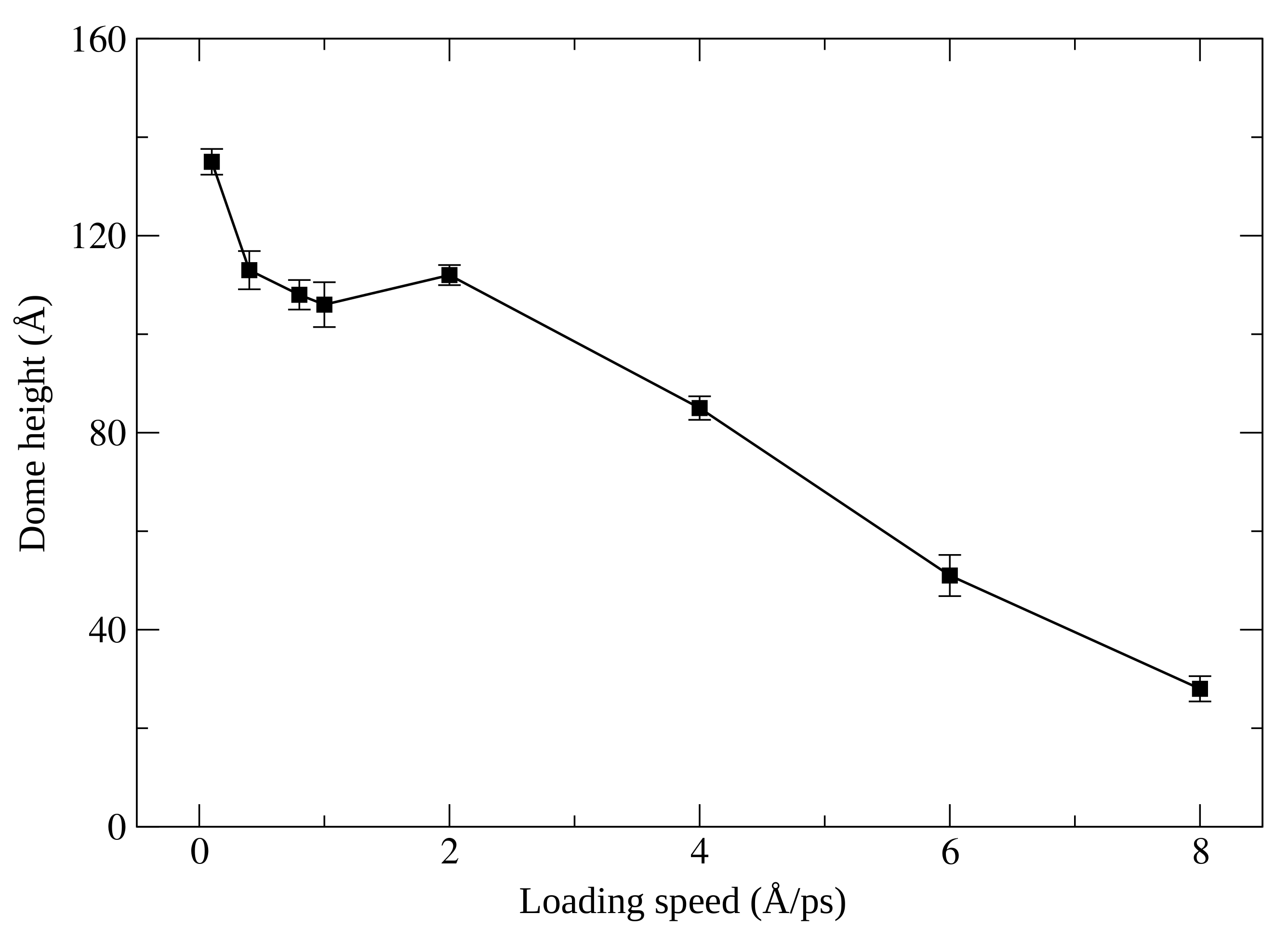
3.3. Dome-Height versus Loading Speed

The deformation of the workpiece is measured from the top surface of the workpiece at the start of the simulation to the bottom surface/point (nearly, in all the simulations, it is a center of the workpiece) obtained by deformation before failure. This distance is termed as dome-height. The deformations reduce with the increase in loading speed, resulting in lower and lower dome-heights, except for 2 Å/ps loading speed where the deformation slightly increases despite the increase in the loading speed. The dome-height at that speed was observed to be approximately 112 Å.
In this study, we have considered four different simulations at each loading speed to avoid model-dependent results for plotting a relation between dome-height and loading speed. We observed consistency in the results for the considered simulations, and we have plotted the statistically averaged results with standard error bars in Figure 7. For very low speeds, that is, <2 Å/ps, the workpiece displays higher abilities to bend as compared to higher speeds. At lower speeds, the deformation is observed throughout the workpiece, starting from the point of contact in the middle. This is contrary to the deformations observed due to the higher loading speed, where localized deformations occur due to the creation of slipping planes. Figure 4 and Figure 6 make this distinction even clearer where it was seen that at a low loading speed of 0.1 Å/ps, the deformation is occurring till the radial end of the workpiece disc, whereas at the high loading speed of 8 Å/ps, the deformation is highly localized, and a major portion of the disc remains undeformed. Therefore, due to different behavior of deformations, we observed a nonlinear relationship between the dome-height and loading speed. A further detailed investigation on the nonlinear relationship between the dome-height and loading speeds with other materials can provide us interesting insights on the fundamental deformation nature of materials as a response to varying speeds of deformation.
Figure 7 depicts the variation of dome-height with respect to loading speed. The highest dome-height of approximately 133 Å was observed at the lowest speed of 0.1 Å/ps, and the lowest dome-height of approximately 29 Å at the highest loading speed of 8 Å/ps. Therefore, we found the inverse relationship between the loading speed and dome-height.
With the increase in loading speeds, the formability of the aluminum workpiece reduces, that is, the dome-height values decrease. It experiences failure as soon as the rate of forming or loading speed is exceeds the internal rate of rearrangement of atoms.

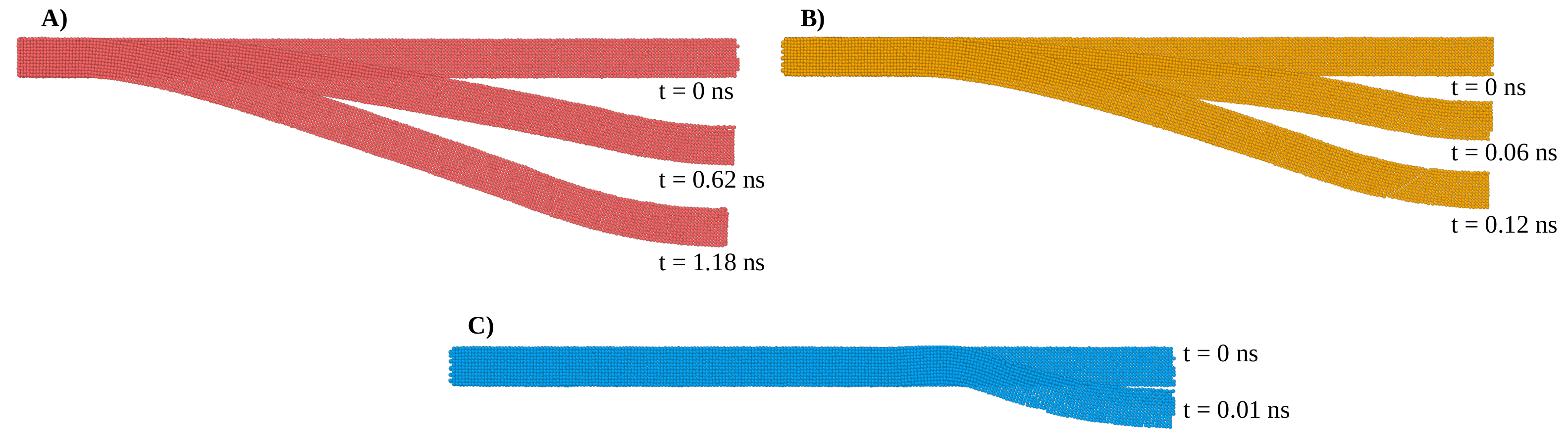
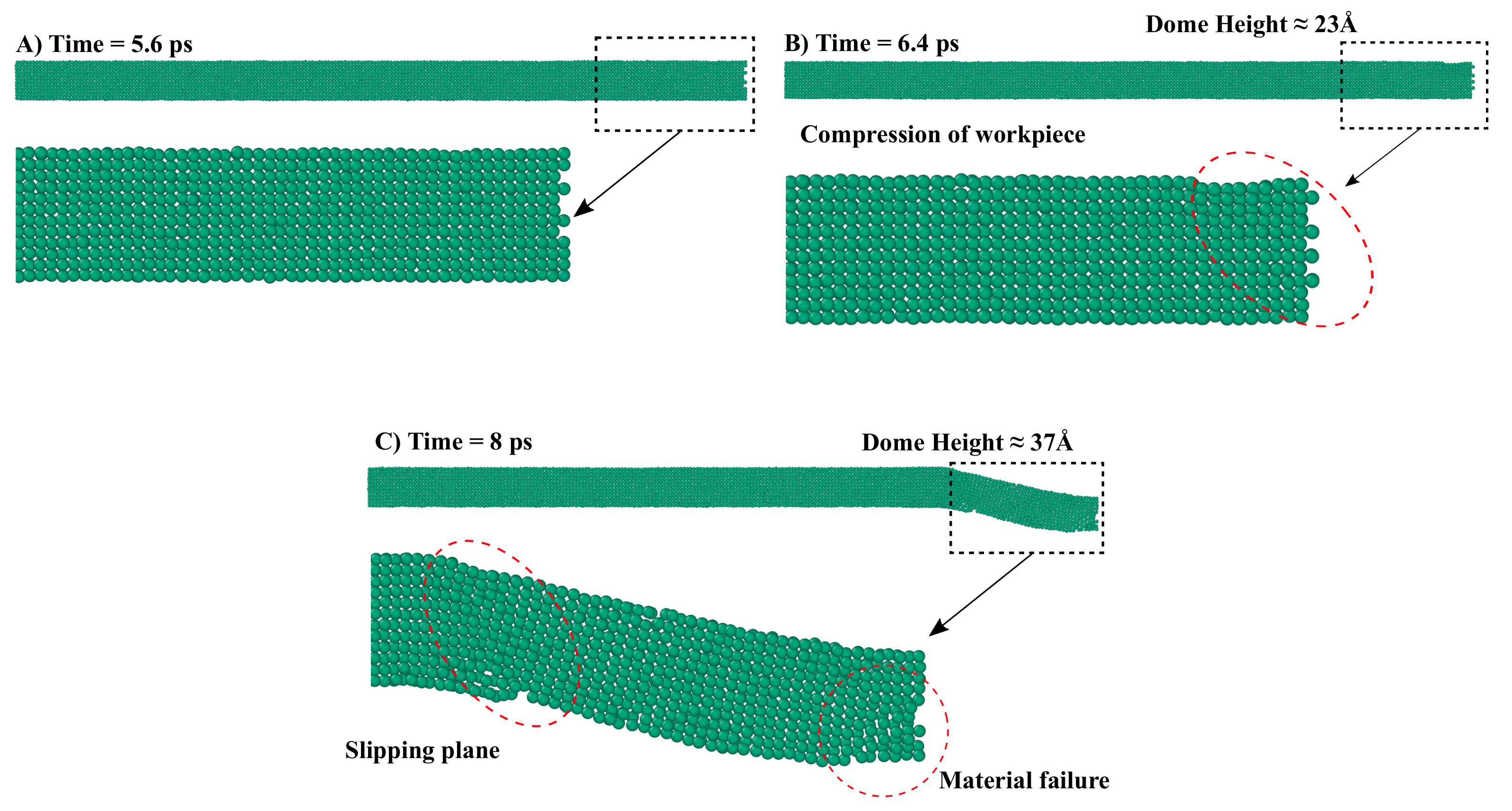
3.4. Failure Patterns

Figure 8 shows different failure patterns observed at low, medium, and high loading speeds. As shown in Figure 8, the deformations progress and rearrangement of atoms of the workpiece are significantly different from one another at different speeds. At low speed (0.1 Å/ps), the nature of the failure is a line-like tear. At medium speed (0.8 Å/ps), the failure appears like a mathematical symbol plus. At high speed (6 Å/ps), the failure is severe as more area of the workpiece is affected by it, and the pattern appears like layered boxes.
The time taken to reach a failure stage at a low loading speed was higher compared to higher loading speeds. The failure snapshots were taken at 1.3, 0.184 and 0.03 ns in Figure 8A–C respectively. This shows that the rate of degradation of material bonds at higher loading speeds is significantly higher. Thus, for higher loading speeds, the atoms remain in nonequilibrated positions, which leads to early failure of the material.

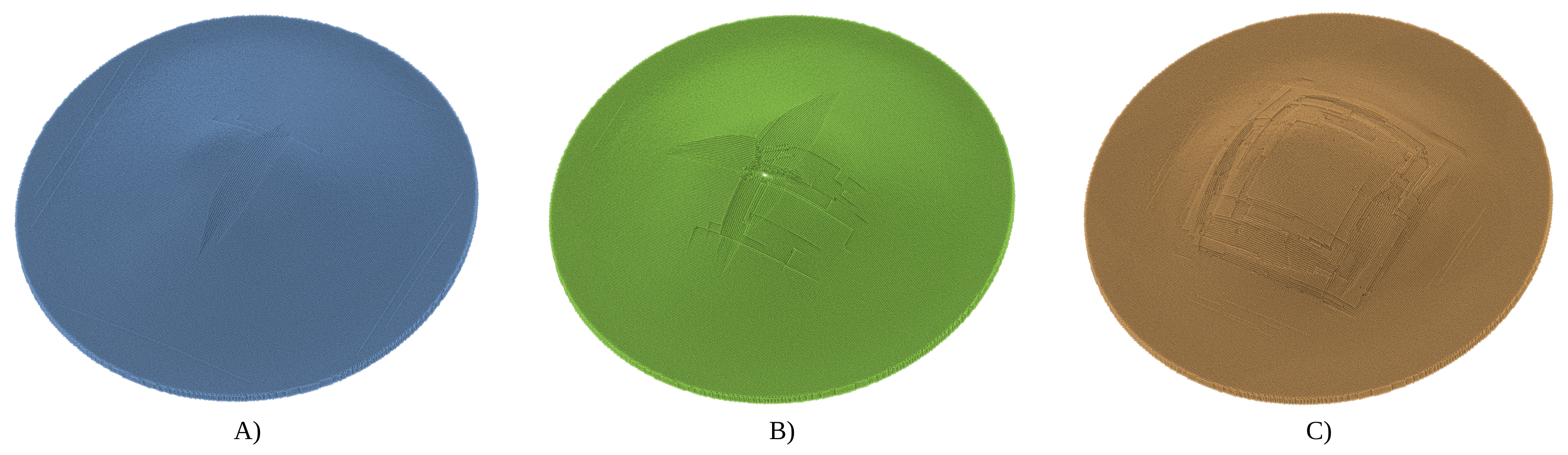
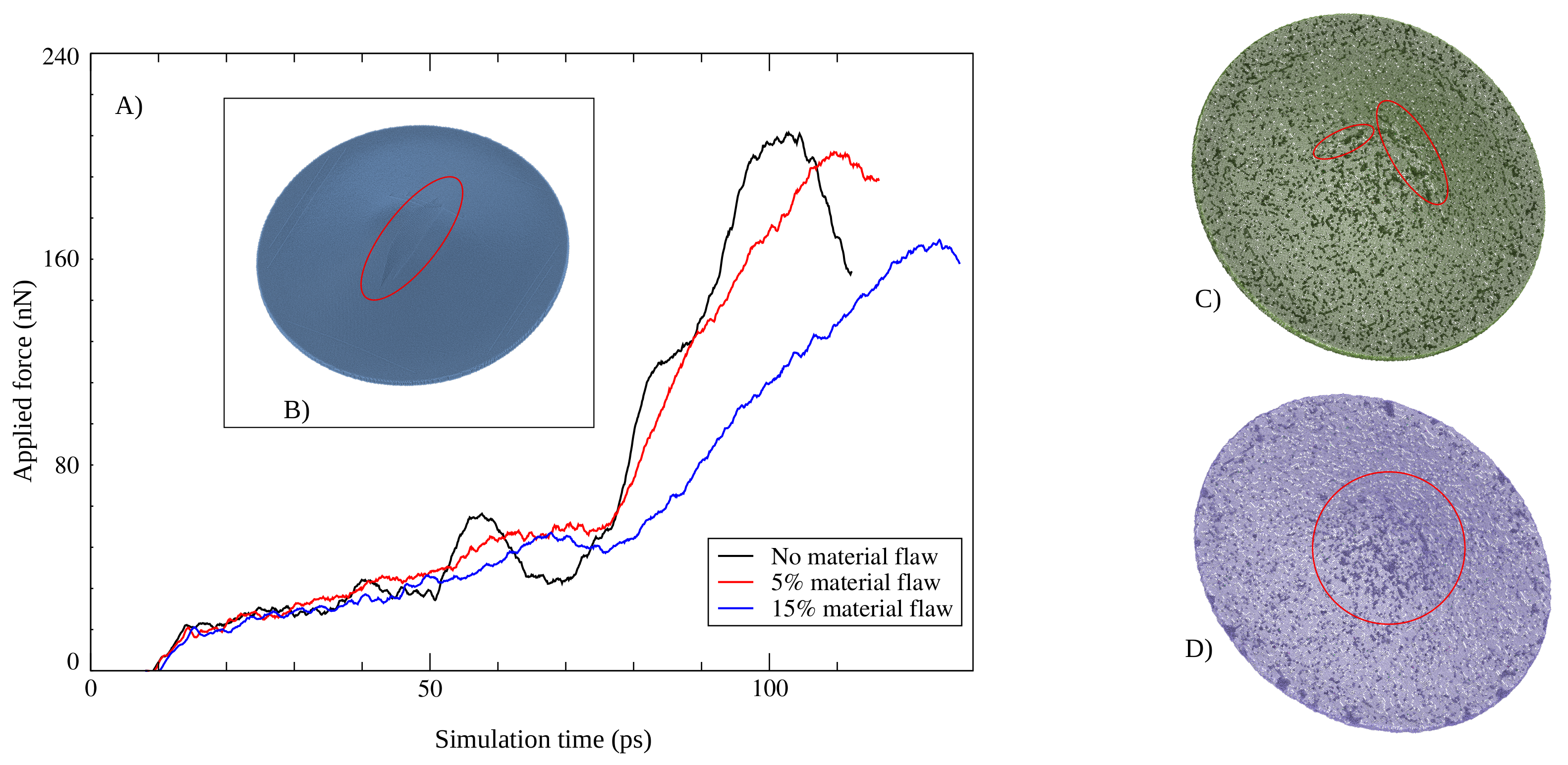
3.5. Influence of Material Flaws

In addition to the cases of different constant loading speeds, we investigated different workpiece models with varying degrees of the material flaw where internal voids ranging from 5 to 20% were considered. In this investigation, one constant speed of 0.1 Å/ps was considered. The punch moves downwards towards the workpiece at a constant speed of 0.1 Å/ps, which is converted to the applied force (expressed in nN) in Figure 9A. The red-colored elliptical markings in Figure 9 B, Figure 9 C indicate the locations of failure or fracture of the models with no material flaw in Figure 9B and 5% voids in Figure 9C, and 15% voids in Figure 9D respectively.
In this study, it is assumed that failure occurs when the applied load crosses the potential barrier, and the atoms start to separate from each other; which can be seen effectively in the force versus simulation time diagram (refer to Figure 9A)), where the force is derived from the negative gradient of the potential energy. Therefore, once the force reaches a peak value, a failure starts, and a significant decrease is observed in forces after the peak.
Here, we compared two different workpiece models with 5% and 15% randomly distributed voids with the no material flaw model. One can observe a significant change in the nature of the failure. The 5% void case has a more regular kind of failure pattern (linear tear) than the case with 15% material flaw, which shows a spluttered pattern of failure. Therefore, the line-like fracture was observed for the no material flaw model, and when the percentage of material flaws was increased, splutter-like failure patterns were prominent.
The introduction of material flaws seems not to produce worse patterns of failure. It creates a random spluttered failure in the middle zone of the workpiece. This is different from the general assumption that voids created in the workpiece by randomly deleting the atoms would indeed result in a faster and more severe failure. In fact, in the workpiece models with voids, the dome-height was noticed to have increased as the voids allow for the movement of slipping planes upon loading, thereby rearranging the atoms in such a way that the formability of the workpiece was comparatively increased. The workpiece does not tear, nor does it get disintegrated. Therefore, for the same loading speed, the ductility of the workpiece increases with the percentage of material flaws.

4. Conclusions

In this work, we studied the high-speed forming process of the aluminum workpiece model by using molecular dynamics simulations. We considered eight different loading speeds, starting from 0.1 up to 8 Å/ps. As special cases of interest, we also studied the different workpiece models with varying degrees of material voids ranging from 5 to 20%.
The outcome from this MD simulation study of the high-speed forming process primarily puts across the following points.
1.
With the increase in the rate of downward movement of the punch towards the workpiece, the ability of the material to take the desired shape (shape of the die) reduces, that is, the dome-height is inversely proportional to the loading speed.
2.
At lower speeds (<2 Å/ps), the deformation is observed throughout the workpiece, starting from the point of contact in the middle. This is contrary to the deformations observed due to the higher loading speeds, where localized deformations occur due to the creation of slipping planes.
3.
The nonlinear relationship between the dome-height and loading speeds is observed because of the difference in deformation mechanisms at low and high loading speeds.
4.
With the increase in the loading speed, the failure patterns developed on the workpiece are increasingly severe.
5.
The introduction of a material flaw does not produce worse patterns of failure. It creates a random spluttered failure in the middle zone of the workpiece. This is contrary to the assumption that random material flaw (random deleting of atoms) would lead to faster and more severe failure.
6.
For the same loading speed, the ductility of the workpiece increases with the increasing percentage of material flaws.
There is further scope for the experimental study of this topic. Exploring other materials with high formability can be done to understand the influence of material flaws and the exact mechanism of rearrangement of atoms leading to higher dome-height. Moreover, the tube joining application of gas detonation can be studied using MD simulations.

Author Contributions

Conceptualization, A.K., S.P.P. and B.M.; methodology, A.K., V.K. and S.P.P.; software, A.K. and S.P.P.; validation, S.P.P.; formal analysis, A.K., V.K., M.N., S.P.P. and B.M.; investigation, A.K., V.K. and S.P.P.; data curation, A.K. and S.P.P.; writing—original draft preparation, A.K., V.K. and S.P.P.; visualization, A.K. and S.P.P.; supervision, M.N., S.P.P. and B.M. All authors have read and agreed to the published version of the manuscript.

Funding

This research received no external funding.

Institutional Review Board Statement

Not applicable.

Informed Consent Statement

Not applicable.

Data Availability Statement

Data can be made available on request.

Acknowledgments

The authors gratefully acknowledge the computing time granted by the JARA Vergabegremium and provided on the JARA Partition part of the supercomputer CLAIX at RWTH Aachen University.

Conflicts of Interest

The authors declare no conflict of interest.

References

  1. Patil, S.P.; Popli, M.; Jenkouk, V.; Markert, B. Numerical modelling of the gas detonation process of sheet metal forming. J. Phys. Conf. Ser. 2016, 734, 032099. [Google Scholar] [CrossRef] [Green Version]
  2. Shepherd, J.E. Structural response of piping to internal gas detonation. J. Press. Vessel. Technol. 2009, 131, 031204. [Google Scholar] [CrossRef]
  3. Mynors, D.J.; Zhang, B. Applications and capabilities of explosive forming. J. Mater. Process. Technol. 2002, 125, 1–25. [Google Scholar] [CrossRef]
  4. Talebi-Anaraki, A.; Chougan, M.; Loh-Mousavi, M.; Maeno, T. Hot Gas Forming of Aluminum Alloy Tubes Using Flame Heating. J. Manuf. Mater. Process. 2020, 4, 56. [Google Scholar] [CrossRef]
  5. Maeno, T.; Mori, K.i.; Sakagami, M.; Nakao, Y.; Talebi-Anaraki, A. Minimisation of Heating Time for Full Hardening in Hot Stamping Using Direct Resistance Heating. J. Manuf. Mater. Process. 2020, 4, 80. [Google Scholar] [CrossRef]
  6. Anaraki, A.T.; Loh-Mousavi, M.; Wang, L.L. Experimental and numerical investigation of the influence of pulsating pressure on hot tube gas forming using oscillating heating. Int. J. Adv. Manuf. Technol. 2018, 97, 3839–3848. [Google Scholar] [CrossRef]
  7. Aoki, T.; Matsuo, J. Molecular dynamics simulations of surface modification and damage formation by gas cluster ion impacts. Nucl. Instrum. Methods Phys. Res. B 2006, 242, 517–519. [Google Scholar] [CrossRef] [Green Version]
  8. Pei, Q.; Lu, C.; Fang, F.; Wu, H. Nanometric cutting of copper: A molecular dynamics study. Comput. Mater. Sci. 2006, 37, 434–441. [Google Scholar] [CrossRef]
  9. Ye, Y.; Biswas, R.; Morris, J.; Bastawros, A.; Chandra, A. Molecular dynamics simulation of nanoscale machining of copper. Nanotechnology 2003, 14, 390. [Google Scholar] [CrossRef]
  10. Perez, D.; Lewis, L.J. Molecular-dynamics study of ablation of solids under femtosecond laser pulses. Phys. Rev. B. 2003, 67, 184102. [Google Scholar] [CrossRef] [Green Version]
  11. Kang, Z.; Li, M.; Tang, Q. Buckling behavior of carbon nanotube-based intramolecular junctions under compression: Molecular dynamics simulation and finite element analysis. Comput. Mater. Sci. 2010, 50, 253–259. [Google Scholar] [CrossRef]
  12. Patil, S.; Heider, Y.; Jansen, C.; Cruz-Chú, E.; Markert, B. A comparative molecular dynamics-phase-field modeling approach to brittle fracture. Comput. Method Appl. Mech. Eng. 2016, 312, 117–129. [Google Scholar] [CrossRef]
  13. Raj, M.; Patil, S.P.; Markert, B. Mechanical Properties of Nacre-Like Composites: A Bottom-Up Approach. J. Compos. Sci. 2020, 4, 35. [Google Scholar] [CrossRef] [Green Version]
  14. Koshiyama, K.; Wada, S. Molecular dynamics simulations of pore formation dynamics during the rupture process of a phospholipid bilayer caused by high-speed equibiaxial stretching. J. Biomech. 2011, 44, 2053–2058. [Google Scholar] [CrossRef] [PubMed]
  15. Shih, C.Y.; Shugaev, M.V.; Wu, C.; Zhigilei, L.V. Generation of subsurface voids, incubation effect, and formation of nanoparticles in short pulse laser interactions with bulk metal targets in liquid: Molecular dynamics study. J. Phys. Chem. C 2017, 121, 16549–16567. [Google Scholar] [CrossRef] [Green Version]
  16. Harrison, D.E., Jr. Application of molecular dynamics simulations to the study of ion-bombarded metal surfaces. Crit. Rev. Solid State Mater. Sci. 1988, 14, s1–s78. [Google Scholar] [CrossRef]
  17. Cui, D.D.; Zhang, L.C. Nano-machining of materials: Understanding the process through molecular dynamics simulation. Adv. Manuf. 2017, 5, 20–34. [Google Scholar] [CrossRef]
  18. Oluwajobi, A.O.; Chen, X. Multi-Pass Nanometric Machining Simulation using the Molecular Dynamics (MD). In Proceedings of the ICPM 2011 the 6th International Congress on Precision Machining, Liverpool, UK, 13–15 September 2011. [Google Scholar]
  19. Li, J.; Liu, B.; Luo, H.; Fang, Q.; Liu, Y.; Liu, Y. A molecular dynamics investigation into plastic deformation mechanism of nanocrystalline copper for different nanoscratching rates. Comput. Mater. Sci. 2016, 118, 66–76. [Google Scholar] [CrossRef]
  20. Nakatani, A. Plastic Deformation Analysis of Nanostructured Metal Using Molecular Dynamics. Proc. JSME 2005, 8, 470–471. [Google Scholar]
  21. Fang, T.H.; Weng, C.I. Three-dimensional molecular dynamics analysis of processing using a pin tool on the atomic scale. Nanotechnology 2000, 11, 148. [Google Scholar] [CrossRef]
  22. Van Swygenhoven, H.; Caro, A.; Farkas, D. A molecular dynamics study of polycrystalline fcc metals at the nanoscale: Grain boundary structure and its influence on plastic deformation. Mater. Sci. Eng. A 2001, 309, 440–444. [Google Scholar] [CrossRef]
  23. Li, J.; Guo, J.; Luo, H.; Fang, Q.; Wu, H.; Zhang, L.; Liu, Y. Study of nanoindentation mechanical response of nanocrystalline structures using molecular dynamics simulations. Appl. Surf. Sci. 2016, 364, 190–200. [Google Scholar] [CrossRef]
  24. Kim, K.J.; Yoon, J.H.; Cho, M.H.; Jang, H. Molecular dynamics simulation of dislocation behavior during nanoindentation on a bicrystal with a Σ = 5 (210) grain boundary. Mater. Lett. 2006, 60, 3367–3372. [Google Scholar] [CrossRef]
  25. Hsu, Q.C.; Wu, C.D.; Fang, T.H. Deformation mechanism and punch taper effects on nanoimprint process by molecular dynamics. Jpn. J. Appl. Phys. 2004, 43, 7665. [Google Scholar] [CrossRef]
  26. Saitoh, K.i.; Sameshima, Y.; Daira, S. Nano-scale modelling and simulation of metal wiredrawing by using molecular dynamics method. World J. Nano Sci. Eng. 2014, 4, 70–83. [Google Scholar] [CrossRef] [Green Version]
  27. Maekawa, K.; Itoh, A. Friction and tool wear in nano-scale machining—A molecular dynamics approach. Wear 1995, 188, 115–122. [Google Scholar] [CrossRef]
  28. Gao, Y.; Urbassek, H.M. Scratching of nanocrystalline metals: A molecular dynamics study of Fe. Appl. Surf. Sci. 2016, 389, 688–695. [Google Scholar] [CrossRef]
  29. Yamakov, V.; Wolf, D.; Phillpot, S.R.; Mukherjee, A.K.; Gleiter, H. Dislocation processes in the deformation of nanocrystalline aluminium by molecular-dynamics simulation. Nat. Mater. 2002, 1, 45–49. [Google Scholar] [CrossRef]
  30. Rentsch, R.; Inasaki, I. Molecular dynamics simulation for abrasive processes. CIRP Ann. 1994, 43, 327–330. [Google Scholar] [CrossRef]
  31. Shimizu, J.; Zhou, L.; Eda, H. Simulation and experimental analysis of super high-speed grinding of ductile material. J. Mater. Process. Technol. 2002, 129, 19–24. [Google Scholar] [CrossRef]
  32. Zhang, J.; Sun, T.; Yan, Y.; Liang, Y.; Dong, S. Molecular dynamics simulation of subsurface deformed layers in AFM-based nanometric cutting process. Appl. Surf. Sci. 2008, 254, 4774–4779. [Google Scholar] [CrossRef]
  33. Ren, J.; Hao, M.; Lv, M.; Wang, S.; Zhu, B. Molecular dynamics research on ultra-high-speed grinding mechanism of monocrystalline nickel. Appl. Surf. Sci. 2018, 455, 629–634. [Google Scholar] [CrossRef]
  34. Patil, S.P.; Heider, Y. A Review on Brittle Fracture Nanomechanics by All-Atom Simulations. Nanomaterials 2019, 9, 1050. [Google Scholar] [CrossRef] [PubMed] [Green Version]
  35. Sahu, Y.; Pradhan, M. Modelling and Simulation of Deep Drawing Process of Circular Cup on AL1200 Using Finite Element Analysis; Springer: Berlin/Heidelberg, Germany, 2020; pp. 29–42. [Google Scholar]
  36. Naik, T.; Hu, Z. Computer Simulation of Deep Drawing Process for a Laminated Composite Cup. In Proceedings of the ASME 2007 International Mechanical Engineering Congress and Exposition, Seattle, WA, USA, 11–15 November 2007; Volume 42975, pp. 567–572. [Google Scholar]
  37. Kumar, S.; Patil, D.H.; Gowda, R.D. Finite Element Simulation of Sheet Metal Deep Drawing Using Explicit Code and Result Validation. Int. Res. J. Eng. Technol. (IRJET) 2015, 2, 1080–1086. [Google Scholar]
  38. De La Rubia, T.D.; Guinan, M. New mechanism of defect production in metals: A molecular-dynamics study of interstitial-dislocation-loop formation in high-energy displacement cascades. Phys. Rev. Lett. 1991, 66, 2766. [Google Scholar] [CrossRef] [PubMed]
  39. Jenkouk, V.; Patil, S.; Markert, B. Joining of tubes by gas detonation forming. J. Phys. Conf. Ser. 2016, 734, 032101. [Google Scholar] [CrossRef]
  40. Patil, S.P.; Prajapati, K.G.; Jenkouk, V.; Olivier, H.; Markert, B. Experimental and numerical studies of sheet metal forming with damage using gas detonation process. Metals 2017, 7, 556. [Google Scholar] [CrossRef] [Green Version]
  41. Patil, S.P.; Murkute, R.; Shirafkan, N.; Markert, B. Deformation of Stacked Metallic Sheets by Shock Wave Loading. Metals 2018, 8, 679. [Google Scholar] [CrossRef] [Green Version]
  42. Patil, S.P.; Fenard, Y.; Bailkeri, S.; Heufer, K.A.; Markert, B. Investigation of Sheet Metal Forming Using a Rapid Compression Machine. Materials 2019, 12, 3957. [Google Scholar] [CrossRef] [Green Version]
  43. Plimpton, S. Fast Parallel Algorithms for Short-Range Molecular Dynamics. J. Comput. Phys. 1995, 117, 1–19. [Google Scholar] [CrossRef] [Green Version]
  44. Stukowski, A. Visualization and analysis of atomistic simulation data with OVITO–the Open Visualization Tool. Model. Simul. Mater. Sci. Eng. 2009, 18, 015012. [Google Scholar] [CrossRef]
  45. Tersoff, J. New empirical model for the structural properties of silicon. Phys. Rev. Lett. 1986, 56, 632. [Google Scholar] [CrossRef]
  46. Tersoff, J. Empirical interatomic potential for carbon, with applications to amorphous carbon. Phys. Rev. Lett. 1988, 61, 2879. [Google Scholar] [CrossRef] [Green Version]
  47. Smith, M. ABAQUS/Standard User’s Manual, Version 6.9; Dassault Systèmes Simulia Corp.: Johnston, RI, USA, 2009. [Google Scholar]
  48. Daw, M.S.; Baskes, M.I. Embedded-atom method: Derivation and application to impurities, surfaces, and other defects in metals. Phys. Rev. B 1984, 29, 6443. [Google Scholar] [CrossRef] [Green Version]
  49. Baskes, M. Modified embedded-atom potentials for cubic materials and impurities. Phys. Rev. B 1992, 46, 2727. [Google Scholar] [CrossRef] [PubMed]
  50. Foiles, S.M. Embedded-atom and related methods for modeling metallic systems. MRS Bull. 1996, 21, 24–28. [Google Scholar] [CrossRef]
  51. Morse, P.M. Diatomic molecules according to the wave mechanics. II. Vibrational levels. Z. Naturforsch. A 1929, 34, 57. [Google Scholar] [CrossRef]
  52. Lim, T.C. The relationship between Lennard-Jones (12-6) and Morse potential functions. Z. Naturforsch. A 2003, 58, 615–617. [Google Scholar] [CrossRef]
  53. Yasar, M. Gas detonation forming process and modeling for efficient spring-back prediction. J. Mater. Process. Technol. 2004, 150, 270–279. [Google Scholar] [CrossRef]
Figure 1. Schematic setup of the all-atom gas detonation forming model. (A) A isometric view, (B) a half sectional isometric view, and (C) 2D front view of the all-atom model. The enlarged view shows gaps between die, workpiece, and workpiece-holder.
Metals 11 00611 g001
Figure 2. Voids in the workpiece: (A) No voids, (B) 5% material flaw, and (C) 15% material flaw in the models.
Metals 11 00611 g002
Figure 3. The snapshots of the forming process at low-speed (1 Å/ps) with the cylindrical punch. (A) At the start of the forming process when t = 0 ps, (B) deformation in progress at t = 24 ps, (C) start of the blanking process t = 80 ps, and (D) a blanked piece from workpiece falls into the die at t = 136 ps.
Metals 11 00611 g003
Figure 4. The snapshots of the workpiece deformation before the complete failure at different time. Different constant loading speeds: (A) A low speed of 0.1 Å/ps, (B) a medium speed of 0.8 Å/ps, and (C) a high speed of 6 Å/ps.
Metals 11 00611 g004
Figure 5. Different stages of loading at 2 Å/ps. (A) denotes the initial condition with detailed view, that is, at Time = 0 ps. (B) denotes the intermediate position with detailed view of the workpiece at Time = 26 ps, where the dome-height at this time is approximately 54 Å. And (C) denotes the position of workpiece just before the failure with detailed view, that is, the position of maximum dome-height of approximately 112 Å.
Metals 11 00611 g005
Figure 6. Different stages of loading at 8 Å/ps. (A) shows the initial condition with detailed view, i.e., at Time = 5.6 ps. (B) shows the intermediate position of the workpiece with detailed view at Time = 6.4 ps, where the dome-height at this time is approximately 23 Å. (C) shows the position of workpiece just at the failure with detailed view, i.e., where the dome-height is approximately 37 Å.
Metals 11 00611 g006
Figure 7. The trend of averaged dome-height of the workpiece against different loading speeds with standard error bars.
Metals 11 00611 g007
Figure 8. Failure patterns at different loading speeds: (A) 0.1 Å/ps, (B) 0.8 Å/ps, and (C) 6 Å/ps.
Metals 11 00611 g008
Figure 9. (A) Applied force versus simulation time. (B) Failure pattern of model with no material flaw, (C) with 5% material flaw, and (D) with 15% material flaw. The spluttered type of failure patterns were observed in the material flaw models.
Metals 11 00611 g009
Publisher’s Note: MDPI stays neutral with regard to jurisdictional claims in published maps and institutional affiliations.

