Article

Mechanical Analysis and Experimental Studies of the Transverse Strain in Wrinkled Metallic Thin Films

1
State Key Laboratory of Advanced Special Steel, Shanghai Key Laboratory of Advanced Ferrometallurgy, School of Materials Science and Engineering, Shanghai University, Shanghai 200444, China
2
CAS Key Laboratory of Magnetic Materials and Devices, Ningbo Institute of Materials Technology and Engineering, Chinese Academy of Sciences, Ningbo 315201, China
3
Zhejiang Province Key Laboratory of Magnetic Materials and Application Technology, Ningbo Institute of Materials Technology and Engineering, Chinese Academy of Sciences, Ningbo 315201, China
4
Center of Materials Science and Optoelectronics Engineering, University of Chinese Academy of Sciences, Beijing 100049, China
*
Authors to whom correspondence should be addressed.
Metals 2021, 11(3), 427; https://doi.org/10.3390/met11030427
Submission received: 5 February 2021 / Revised: 24 February 2021 / Accepted: 28 February 2021 / Published: 5 March 2021

Abstract

:
The wrinkling structures, which can greatly improve the stretchability of the metallic thin films, have been widely used in the preparation of stretchable devices. However, the artificial wrinkling structures are often accompanied by the generation of microcracks, which seriously affect the performance of the devices. In this work, by establishing the corresponding model, the transverse strain of the longitudinally prestrained continuous film and the strip film is mechanically analyzed, which is verified by experimental results; for the strain of blank substrate, the error of the model was about 3.7%. It is difficult to avoid the generation of microcracks with continuous films, but strip films can avoid the generation of microcracks to a certain extent. The experimental results illustrate the various factors affecting the generation of microcracks. The transverse strain of the film is proportional to the substrate’s Young’s modulus, Poisson’s ratio, thickness, and prestrain and is basically inversely proportional to the strip film’s Young’s modulus, thickness, and strip interval. Our results provide deeper knowledge for choosing proper metallic materials to fabricate stretchable wrinkled devices.

1. Introduction

With the development of the application of wearable equipment, stretchable electronic devices have attracted wide attention [1,2,3]. They have a wide range of applications including disposable electronics, electronic skins, and flexible displays, due to their reliable portability, excellent stretchability and bendability, fit to the human body, elastic deformation, etc. [4,5,6,7,8,9,10]. Presently, stretchable devices are mainly composed of polymer substrates and functional layers directly coated or multi-step transferred onto them. However, the elasticity of functional layers and polymer substrates is significantly different: for materials with a certain tensile capacity, such as carbon nanotubes and Ag nanowire, the functional layer can be stretched [11,12] and bent [13] to a certain extent. However, for many functional materials, such as metallic thin films, are almost non-stretchable [14,15,16], and will crack under a very small tensile strain, thus making the device unusable.
In recent years, wrinkling structures, which can greatly improve the stretchability of the thin films, have been widely used in the preparation of stretchable supercapacitors, field-effect transistor, spin valve, diodes, integrated circuits, etc. [9,10,11,12,17,18,19,20,21,22,23,24,25]. Khang et al. [23] used chemical bonds to bond monocrystal strips to the prestrain (εpre) polydimethylsiloxane (PDMS) and released the prestrain strips to form regular and controllable monocrystal wrinkled strips. The metal oxide semiconductor field-effect transistor and diodes prepared on this basis can maintain their properties when compressed or stretched to the prestrain range. Jiang et al. [24] analyzed the influence of prestrain and mechanical properties of the film and substrate on the wavelength and amplitude of the wrinkled structure in detail. Based on the principle of the lowest energy of the film–substrate system after release, the formula of wavelength and amplitude was optimized, and the influence of tensile amount on the wavelength and amplitude of the wrinkled film was further deduced when the film was stretched again. Recently, we prepared a wrinkled spin-valve through prestrain PDMS, and the device could maintain good sensitivity with a large magnetoresistance effect in the device [25]. However, the wrinkled metallic thin films are often accompanied by many microcracks parallel to the prestrain direction, which will affect the performance of the device. At present, there is no systematic study on the formation of microcracks, so it is difficult to determine how various factors affect the generation of microcracks, and what the main and secondary factors are; understanding these can better prevent the generation of microcracks. In this work, by preparing wrinkled a structure with different prestrains and different strip intervalss of metallic thin films, we explored the factors influencing the formation of microcracks in wrinkled metallic thin films. The transverse strain caused by Poisson effect of film is the cause of microcracks, and the formula of transverse strain of the film was obtained through mechanical analysis, which was verified by experimental results in different wrinkled metallic thin films. The analysis and conclusions are very important for the preparation of stretchable wrinkled metallic thin films with good properties.

2. Materials and Methods

Several metallic thin films, including Ta (2.5 nm)/CoFeB (20 nm)/Ta (2.5 nm) film, Ta (2.5 nm)/Co (20 nm)/Ta (2.5 nm) film, Ta (2.5 nm)/Pt (20 nm)/Ta (2.5 nm) film, and Ta (25 nm) film, were chosen and sputtering-deposited on PDMS substrates with different uniaxial tensile prestrains. The PDMS resin and the curing agent were proportioned in a ratio of 10:1, and the PDMS was evenly distributed by spin-coating at 100 rpm/min for 20 s. After spin-coating at 250 rpm/min for 120 s, it was cured at 80 °C for 120 min. The thickness of film and PDMS was measured by step profiler (Bruker, DEKTAK XT, Billerica, MA, USA). The surface morphology of the films was observed by optical microscope and atomic force microscopy (AFM, Bruker Dimension ICON, Billerica, MA, USA).

3. Results

3.1. The Cause of Microcrack Formation in Wrinkled Metallic Thin Films

As shown in Figure 1, in an ideal state, when the elastic substrate PDMS with length L and width W is stretched horizontally to L(1 + εpre), due to the Poisson effect (Poisson’s ratio ν), the width in the vertical direction shrinks to w(W(1 − νεpre)). Then, metallic thin films are deposited on the surface of the stretched substrate. After releasing the prestrain, the horizontal direction of the substrate shrinks from L(1 + εpre) to L, and the thin film is uniformly compressed in this direction to form an ordered wrinkled nanostructure. In the vertical direction, the substrate will try to expand from w to W but can only be expanded to (w + x) due to the clamping of the metallic thin films, and the tensile strain (x/w) of metallic thin films in the vertical direction may produce microcracks. On the other hand, the upper surface of the substrate is bound by the film, while the lower surface is free to relax, which leads to the bending of the substrate.
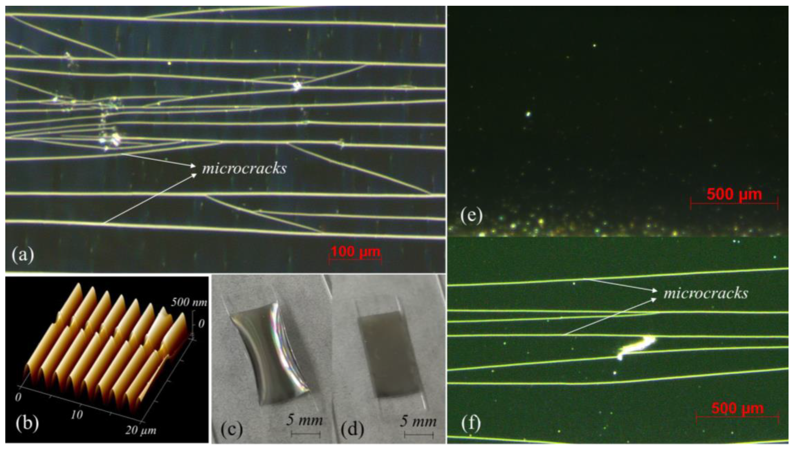
When the prestrain is large, there are many microcracks in the wrinkled film after releasing the prestrain. Figure 2a shows the optical image of a 30% prestrain wrinkled Ta/CoFeB/Ta film with many microcracks, which can also be observed in the AFM image (Figure 2b). When the prestrain is small, about 4% prestrain of CoFeB film and 10% prestrain of Pt film, the film will not form microcracks after releasing the prestrain. Figure 2c shows a 10% prestrain Pt film, which is curved and has no microcracks on the surface (Figure 2e), but after the film is flattened (Figure 2d), microcracks will occur as shown in Figure 2f.

3.2. Transverse Strain of the Metallic Thin Films

How do the parameters of film and substrate, such as thickness, Young’s modulus, Poisson’s ratio, and prestrain, affect the formation of microcracks in wrinkled metallic thin films? Intuitively speaking, microcracks are caused by the transverse tensile strain of the film. When the strain exceeds a certain critical value, the film will break and produce microcracks. For the convenience of calculation, we equate the curved cross-section at red dotted line in Figure 1 to the horizontal section and shift the strain on the lower surface of the substrate to one side, as shown in Figure 3a. The thickness of the film is much thinner than the substrate, and the Young’s modulus of film is very large, so the shape variables of the upper and lower surfaces of thin film are considered equal. That is, if the width of the film changes from w to w + x, then the strain of the film (εf) is:
ε f = x / w
so
x = ε f w
If the width of the upper surface of the substrate changes from the original W to w + x, then the upper surface strain is:
W w x W
The width of the lower surface of the substrate is restored to the original W, and the strain is 0. As the substrate is relatively thin, it can be considered that the expansion from the upper surface to the lower surface is linear, as shown in Figure 3b. The average strain of the substrate can be calculated by dividing the strain integral by the substrate thickness:
ε s = W w x 2 W = W w ε f w 2 W
The force balance between the film and the substrate:
ε f E f h f L = E s h s L W w ε f w 2 W
ε f = ( W w ) E s h s 2 W E f h f + w E s h s
Divide the numerator and the denominator by W:
ε f = ν ε p r e E s h s 2 E f h f + E s h s ( 1 ν ε p r e )
where Ef and Es is the Young’s modulus of film and substrate, respectively, hf and hs is the thickness of the film and the substrate, respectively. Eshs(1 − νεpre) is one order of magnitude less than 2Efhf, and can be ignored for convenience of calculation:
ε f = ν ε p r e 1 2 E s E f h s h f
After the prestrain is released, due to the bend of the substrate, we cannot directly measure the length change in the vertical direction and calculate the strain of the film. However, we find that the middle part of the curved sample is bright and the edge is dark, as shown in Figure 3c. The light irradiates the surface of the sample vertically, and the curved surface reflects the light with the radius as normal. The inclination of the two sides of the sample is large, so the reflected light cannot enter the microscope lens, while the reflected light from the relatively flat middle areas can, so there are dark areas on both sides and bright areas in the middle. The width of the bright region is independent of the sample size but is determined by the inclination of the sample (Figure 3d). For this microscope, the inclination is a fixed value; that is, the bright areas are arcs with a radian of θ (Figure 3e). If the width of the bright area is L, the corresponding curvature radius is:
R = L 2 sin θ 2
so the actual width of the bright film is , and the actual width of the lower surface of the substrate is (R + d)θ. When the prestrain is very small, it can be considered that the lower surface of the substrate can recover to its original width, then the prestrain is the width of the substrate and the film is:
( R + d ) θ ( 1 ν ε p r e )
Before releasing the prestrain, the width of the film is (R + d)θ(1 − νεpre), and after releasing the prestrain, the width of the film is , so the strain of the film is:
ε f = R θ ( R + d ) θ ( 1 ν ε p r e ) ( R + d ) θ ( 1 ν ε p r e ) = ν ε p r e ( R + d ) d ( R + d ) ( 1 ν ε p r e )
Plugging this into Formula (7), we get:
R = d 1 ν ε p r e ν ε p r e ( 1 + E s h s 2 E f h f )
By flattening the substrate over the glass and gradually raising one end of the glass, the bright surface will suddenly become dark at a certain angle, just like the dark sides of the curved substrate. The slant angle of the glass slice at this time is the same as the bend angle at the bright and dark junction of the bending sample, and the slant angle of the glass sheet is measured to be about 10° at this time. Then, according to the width of the bright area measured by the optical microscope, the curvature radius R of the bending film can be calculated.

3.3. Strain of Continuous Metallic Film

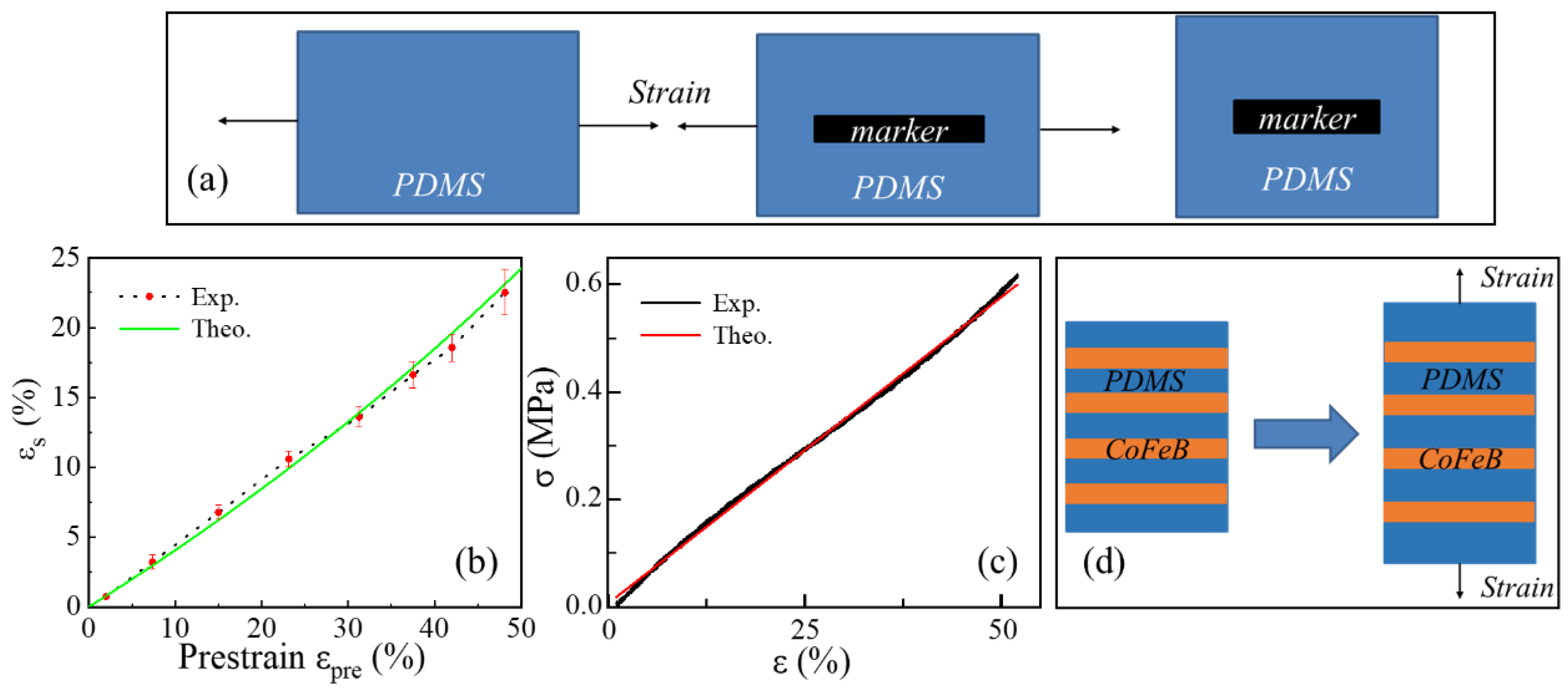
In order to ensure the accuracy of the calculation results, the mechanical properties of PDMS substrate and PDMS with Ta/CoFeB/Ta thin films were measured. Figure 4a shows the measurement method of Poisson’s ratio of PDMS. PDMS was first stretched to a certain tensile strain, then a marker was made along the stretch direction, and finally, the PDMS was gradually released to the original length and the width of the marker was measured step by step. Thus, the width of the marker under different tensile strains can be obtained, and the transverse strain of PDMS below the markers under different tensile strains can be calculated. In Figure 4b, the red point is the experimental data of PDMS transverse strain, and the green curve is the theoretical fitting value. When ν = 0.4, the theoretical value is in good agreement with the experimental value, so ν = 0.4 is taken for calculation. Figure 4c shows the stress–strain curve of PDMS within the elastic range of 0–50%, the Young’s modulus of PDMS was obtained by fitting Es = 1.14 MPa. For the film on PDMS substrate, the mechanical properties of the film may be different from those of the bulk material, so it is necessary to measure the mechanical properties of the films. The PDMS was cut into long strips (about 30 mm × 6 mm), and the strip metallic CoFeB film was prepared along the transverse direction and covered with them (the strip film was about 6 mm long), as shown in Figure 4d. The PDMS substrate is slowly stretched along the length direction, and the tension received at the strip is equal to that received at the blank substrate:
( E f h f + E s h s ) ε f = E s h s ε s
where εs is the strain of blank substrate. Ef of CoFeB film is about 84 GPa by calculation.
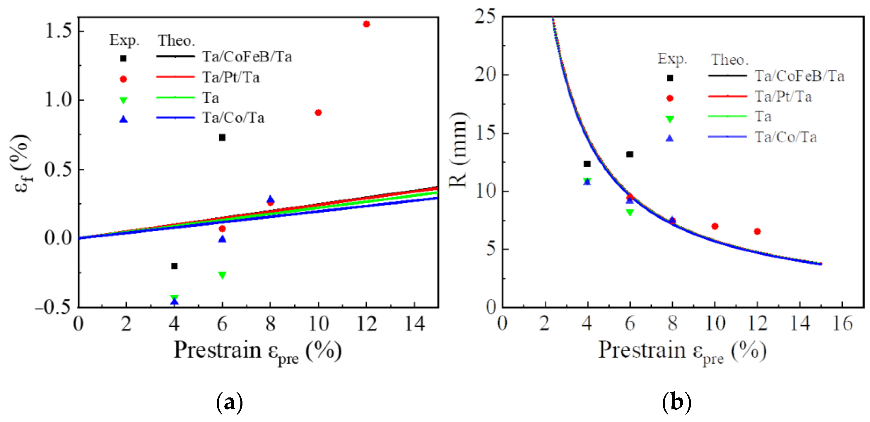
In order to verify the above analysis, films of different metallic materials under different prestrains are prepared. When the prestrain of a metallic film reaches a certain value, microcracks will appear on the bending film, and the strain value and curvature radius of the film will increase rapidly due to its influence. Therefore, when microcracks appear in the film, the amount of prestrain will not increase in the experiment, and the last point of each kind of film corresponds to the amount of prestrain that microcracks just appear, as shown in Figure 5a. The critical prestrain for microcracks in most metallic films is very small, 4–6%, and only Ta/Pt/Ta reaches 10% in this experiment. Therefore, for metallic films, the critical prestrain cannot be greatly improved by adjusting the parameters of the film and substrate. In addition, after the film is flattened, a large number of microcracks appear in the film under small prestrain, so it is difficult to avoid microcracks in continuous metallic films. Furthermore, the theoretical value of the film strain is quite different from the experimental value. When the prestrain is small, the experimental value of the film strain is negative, which is obviously contrary to reality. However, with the increase in the prestrain, the film strain value increases rapidly and exceeds the theoretical value, which is also reflected in Figure 5b. Figure 5b shows the corresponding radius of curvature: when the prestrain is small, the experimental calculated value of the curvature radius of the film is smaller than the theoretical value, and with the increase of the prestrain, the experimental value gradually becomes larger than the theoretical value, which is the same as the trend of the film strain. The reason for this phenomenon is that the order of error in the experimental calculation is larger than the order of the film strain. The sources of errors are as follows: the measurement of the bright area width of the bending film, the measurement of the edge angle of the bright area, the fact that the film substrate cannot be bent to an ideal extent due to the influence of gravity and other factors, and so on. These errors add up to orders of magnitude (~1%) much larger than those of the thin film strain (~0.1%), so it is difficult to determine the film strain and curvature radius quantitatively; only qualitative analysis of its trend changes is possible, but its accuracy of theoretical analysis cannot be verified through experiments. Therefore, the striped films are prepared for further analysis.

3.4. Strain of Strip Metallic Films

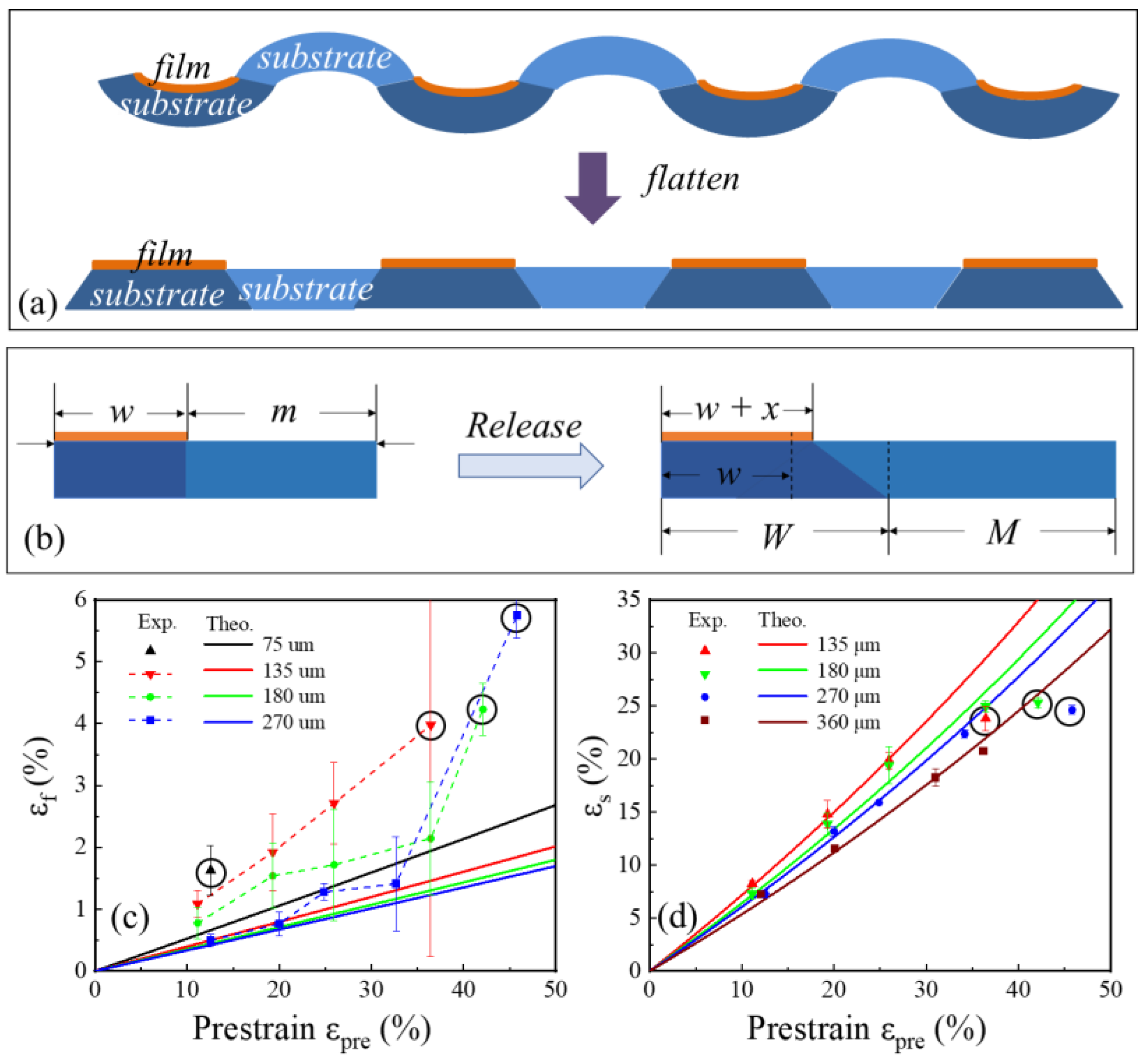
Like continuous films, strip films also appear curved, and two curved strips make the blank substrate in the middle appear upward curved. In practice, the substrate can be equivalent to a complementary trapezoidal link due to the small width and small curvature of the strip film, as shown in Figure 6a. Therefore, the film will not only be subjected to stress from the underlying substrate, but also from the adjacent blank substrate. The proportion of the strip film before releasing the prestrain is y, and the proportion of the blank strip substrate is (1 − y), so the relationship in Figure 6b can be obtained:
m = w 1 y y
M = W 1 y y
in the same way as the analysis of continuous film, and the strain of strip film can be obtained:
ε f = x / w
The strain of substrate under the film is:
ε s 1 = W w x 2 W = W w ε f w 2 W
The strain of blank substrate is:
ε s 2 = W w x 2 L = y 1 y W w ε f w 2 W
The force balance between the film and the substrate:
ε f E f h f L = E s h s L W w ε f w 2 W ( 1 + y 1 y )
ε f = ( W w ) E s h s 2 W ( 1 y ) E f h f + w E s h s
Dividing the numerator and the denominator by W,
ε f = ν ε p r e E s h s 2 ( 1 y ) E f h f + E s h s ( 1 ν ε p r e )
The strain of the blank substrate is:
ε s 2 = ν ε p r e 1 ν ε p r e E f h f + E s h s ( 1 ν ε p r e ) 2 ( 1 y ) E f h f + E s h s ( 1 ν ε p r e )
The 100 μm width CoFeB films with different interval widths were prepared, and compared with the continuous film in Figure 5a, the error between the theoretical value and the experimental value of the strip film strain is reduced but was still around 100%, as shown in Figure 6c. The main source of error is the measurement error of the transverse strain of the strip film, which is in the same order of magnitude as the strip film strain, so it can only be analyzed qualitatively. It is the same with the theoretical calculation that the transverse strain of the strip film varies linearly with the prestrain, and the larger the strip film spacing is, the smaller the transverse strain is. The critical prestrain of the strip film is much larger than that of the continuous film. The strip films with intervals of 75 μm show microcracks when the prestrain exceeds 10%, while the strip films with interval of 135, 180, and 270 μm show microcracks when the prestrain is about 40%, which are circled in black in Figure 6c. Among them, we first obtained that the 135 μm spaced strip films produced microcracks at 37% prestrain, based on the fact that the critical transverse strain of all types of strip films was the same when microcracks occurred. According to formula (21), it is deduced that the strip with interval of 180 μm will produce microcracks under 42% prestrain, and the strip with interval of 270 μm will produce microcracks under 45% prestrain. This is similar to the experimental data (42 and 46%) in Figure 6c, so the formula can predict the prestrain range of microcracks formation in strip films well. Figure 6d shows a blank interval substrate strain with different widths, and the experimental values coincide well with the theoretical value when there is no microcrack. As shown in Table 1, among the 15 groups of blank substrate strain data, only four groups of theoretical values exceed the range of experimental values, which are marked in red. In addition, all errors between theoretical values and experimental values are less than 10%, and the average error is about 3.7%, which is far less than the error of the strip film (~100%). Considering the errors in the width measurement and prestrain measurement, the theoretical formula of blank substrate strain predicts the actual situation well. The film strain formula and the blank substrate strain formula can be derived from each other; thus, verifying the accuracy of the blank substrate strain formula also indicates that the thin film strain formula is accurate, and the process and result of formula derivation are correct. When the strip films show microcracks, which are circled in black in Figure 6d, the tensile stress of the blank substrate from the strip film decreases, so the substrate strain decreases, which is obviously less than the theoretical value.
The parameters can be adjusted according to the formula when preparing stretchable wrinkled films without microcracks for wearable devices. The maximum stretching amount of human skin can reach 50% [26], so the prestrain should be more than 50%; in this case, the thickness of the films becomes the main factor affecting the wavelength and amplitude of the wrinkled structure [23], which will affect properties of the devices [10]. Therefore, the thickness of the films has an optimal range to ensure the properties of the device, which may be 30 or 50 nm. The remaining parameters that are most easily changed are the thickness of the substrate and the width and interval of the strip films. They can be adjusted flexibly according to different experimental conditions. For example, for 30 nm thick and 100 μm wide wrinkled strip film with 50% prestrain and 200 μm thick substrate, the strip interval of 200–300 μm can prevent the generation of microcracks, which is consistent with our previous work [25]. However, the model we established is still relatively simple, and many factors have been simplified. For example, the strain of the substrate under the strip film is approximately linear (Figure 6a), which is more complicated in practice. The stress–strain curve of the striped film is not a simple linear relationship, because elastic-plastic deformation will occur when the strain of the film is large. Therefore, the average modulus of the film in the strain process is experimentally calculated to reduce the error in Figure 4d. In addition, there will always be some impurities in the strip films, where microcracks are more likely to occur, which is where we simplify. Generally speaking, our model needs further research and optimization, which is also the direction of our future research.

4. Conclusions

This work focuses on the formation of microcracks in prestrained wrinkled metallic thin films; the causes of microcrack formation are studied and analyzed in detail. When the longitudinal prestrain is released, the Poisson effect leads to the transverse stretching of the film and thus microcracks appear. Through mechanical analysis, the formula of transverse strain of the film produced by prestrain is obtained, which is verified by experimental results in several wrinkled metallic thin films. For the strain of blank substrate, the average error of the formula is about 3.7%. The transverse strain of the film increases with the increase of the substrate’s Young’s modulus, Poisson’s ratio, thickness, and prestrain and decreases with the increase of the strip film’s Young’s modulus, thickness, and strip interval. According to the experimental results, microcracks can be mostly avoided when the 100 μm wide strip film is spaced at 200–300 μm, and the specific parameters can be adjusted more conveniently according to the formulas to meet the performance requirements. The analysis and conclusion are very important for the preparation of stretchable wrinkled metallic films with good properties, but our model needs further research and improvement in the future.

Author Contributions

Conceptualization, B.W.; Methodology, T.N. and B.W.; Investigation, T.N., B.L., Y.X., H.Y.; Writing—Original Draft Preparation, T.N.; Writing—Review and Editing, T.N. and B.W.; Supervision, B.W.; Funding Acquisition, B.W., M.Z., and R.-W.L. All authors have read and agreed to the published version of the manuscript.

Funding

This work was supported by National Key Technologies R&D Program of China (2016YFA0201102), the National Natural Science Foundation of China (51871232, 51871233, and 51931011), the Ningbo Science and Technology Bureau (2018B10060), Ningbo Natural Science Foundation (2019A610054).

Institutional Review Board Statement

Not applicable.

Informed Consent Statement

Not applicable.

Data Availability Statement

All data generated or analyzed during this study are included in this article.

Conflicts of Interest

The authors declare no conflict of interest.

References

  1. Jayathilaka, W.A.D.M.; Qi, K.; Qin, Y.L.; Chinnappan, A.; Serrano-García, W.; Baskar, C.; Wang, H.B.; He, J.X.; Cui, S.Z.; Thomas, S.W.; et al. Significance of Nanomaterials in Wearables: A Review on Wearable Actuators and Sensors. Adv. Mater. 2019, 31, 1805921. [Google Scholar] [CrossRef] [PubMed]
  2. Sheng, P.; Wang, B.M.; Li, R.W. Flexible Magnetic Thin Films and Devices. J. Semicon. 2018, 39, 011006. [Google Scholar] [CrossRef]
  3. Someya, T.; Kato, Y.; Sekitani, T.; Iba, S.; Noguchi, Y.; Murase, Y.; Kawaguchi, H.; Sakurai, T. Conformable, flexible, large-area networks of pressure and thermal sensors with organic transistor active matrixes. Proc. Natl. Acad. Sci. USA 2005, 102, 12321–12325. [Google Scholar] [CrossRef] [PubMed] [Green Version]
  4. Wang, S.Y.; Chen, C.S.; Yu, Z.H.; He, Y.L.; Chen, X.Y.; Wan, Q.; Shi, Y.; Zhang, D.W.; Zhou, H.; Wang, X.R.; et al. A MoS2/PTCDA Hybrid Heterojunction Synapse with Efficient Photoelectric Dual Modulation and Versatility. Adv. Mater. 2019, 31, 1806227. [Google Scholar] [CrossRef] [PubMed]
  5. Cui, W.; King, D.R.; Huang, Y.; Chen, L.; Sun, T.L.; Guo, Y.; Saruwatari, Y.; Hui, C.-Y.; Kurokawa, T.; Gong, J.P. Fiber-Reinforced Viscoelastomers Show Extraordinary Crack Resistance That Exceeds Metals. Adv. Mater. 2020, 32, 1907180. [Google Scholar] [CrossRef] [PubMed]
  6. Qiao, X.Y.; Wen, X.C.; Wang, B.M.; Bai, Y.H.; Zhan, Q.F.; Xu, X.H.; Li, R.W. Enhanced Stress-Invariance of Magnetization Direction in Magnetic Thin Films. Appl. Phys. Lett. 2017, 111, 132405. [Google Scholar] [CrossRef] [Green Version]
  7. Nam, H.M.; Seo, D.M.; Yun, H.D.; Thangavel, G.; Park, L.S.; Nam, S.Y. Transparent Conducting Film Fabricated by Metal Mesh Method with Ag and Cu@Ag Mixture Nanoparticle Pastes. Metals 2017, 7, 176. [Google Scholar] [CrossRef] [Green Version]
  8. Guo, Y.; Zhong, M.J.; Fang, Z.W.; Wan, P.B.; Yu, G.H. A Wearable Transient Pressure Sensor Made with MXene Nanosheets for Sensitive Broad-Range Human-Machine Interfacing. Nano Lett. 2019, 19, 1143–1150. [Google Scholar] [CrossRef]
  9. Chen, X.; Hutchinson, J.W. Herringbone Buckling Patterns of Compressed Thin Films on Compliant Substrates. J. Appl. Mech. 2004, 71, 597–603. [Google Scholar] [CrossRef]
  10. Zhang, S.L.; Zhan, Q.F.; Yu, Y.; Liu, L.P.; Li, H.H.; Yang, H.L.; Xie, Y.L.; Wang, B.M.; Xie, S.H.; Li, R.W. Surface Morphology and Magnetic Property of Wrinkled FeGa Thin Films Fabricated on Elastic Polydimethylsiloxane. Appl. Phys. Lett. 2016, 108, 102409. [Google Scholar] [CrossRef]
  11. Yu, C.J.; Masarapu, C.; Rong, J.P.; Wei, B.Q.; Jiang, H.Q. Stretchable Supercapacitors Based on Buckled Single-Walled Carbon Nanotube Macrofilms. Adv. Mater. 2009, 21, 4793–4797. [Google Scholar] [CrossRef] [PubMed]
  12. Niu, Z.Q.; Dong, H.B.; Zhu, B.W.; Li, J.Z.; Hng, H.H.; Zhou, W.Y.; Chen, X.D.; Xie, S.S. Highly Stretchable, Integrated Supercapacitors Based on Single-Walled Carbon Nanotube Films with Continuous Reticulate Architecture. Adv. Mater. 2013, 25, 1058–1064. [Google Scholar] [CrossRef] [PubMed]
  13. Kim, Y.J.; Kim, G.; Kim, H.K. Study of Brush-Painted Ag Nanowire Network on Flexible Invar Metal Substrate for Curved Thin Film Heater. Metals 2019, 9, 1073. [Google Scholar] [CrossRef] [Green Version]
  14. Tang, Z.H.; Wang, B.M.; Yang, H.L.; Xu, X.Y.; Liu, Y.W.; Sun, D.D.; Xia, L.X.; Zhan, Q.F.; Chen, B.; Tang, M.H.; et al. Magneto-Mechanical Coupling Effect in Amorphous Co40Fe40B20 Films Grown on Flexible Substrates. Appl. Phys. Lett. 2014, 105, 103504. [Google Scholar] [CrossRef]
  15. Wen, X.C.; Wang, B.M.; Sheng, P.; Hu, S.; Yang, H.L.; Pei, K.; Zhan, Q.F.; Xia, W.X.; Xu, H.; Li, R.W. Determination of Stress-Coefficient of Magnetoelastic Anisotropy in Flexible Amorphous CoFeB Film by Anisotropic Magnetoresistance. Appl. Phys. Lett. 2017, 111, 142403. [Google Scholar] [CrossRef]
  16. Chen, X.Y.; Wang, B.M.; Wen, X.C.; Sheng, P.; Pravarthana, D.; Yang, H.L.; Xie, Y.L.; Liu, H.G.; Xu, X.H.; Li, R.W. Stress-Coefficient of Magnetoelastic Anisotropy in Flexible Fe, Co and Ni Thin Films. J. Magn. Magn. Mater. 2020, 505, 166750. [Google Scholar] [CrossRef]
  17. Efimenko, K.; Rackaitis, M.; Manias, E.; Vaziri, A.; Mahadevan, L.; Genzer, J. Nested Self-Similar Wrinkling Patterns in Skins. Nat. Mater. 2005, 4, 293–297. [Google Scholar] [CrossRef] [PubMed]
  18. Kim, D.H.; Ahn, J.H.; Choi, W.M.; Kim, H.S.; Kim, T.H.; Song, J.; Huang, Y.Y.; Liu, Z.; Lu, C.; Rogers, J.A. Stretchable and Foldable Silicon Integrated Circuits. Science 2008, 320, 507–511. [Google Scholar] [CrossRef] [PubMed] [Green Version]
  19. Melzer, M.; Lin, G.; Makarov, D.; Schmidt, O.G. Stretchable Spin Valves on Elastomer Membranes by Predetermined Periodic Fracture and Random Wrinkling. Adv. Mater. 2012, 24, 6468–6472. [Google Scholar] [CrossRef]
  20. Um, D.S.; Lim, S.; Lee, Y.; Lee, H.; Kim, H.J.; Yen, W.C.; Chueh, Y.L.; Ko, H. Vacuum-Induced Wrinkle Arrays of InGaAs Semiconductor Nanomembranes on Polydimethylsiloxane Microwell Arrays. ACS Nano 2014, 8, 3080–3087. [Google Scholar] [CrossRef]
  21. Cerda, E.; Mahadevan, L. Geometry and Physics of Wrinkling. Phys. Rev. Lett. 2003, 90, 074302. [Google Scholar] [CrossRef] [PubMed] [Green Version]
  22. White, M.S.; Kaltenbrunner, M.; Głowacki, E.D.; Gutnichenko, K.; Kettlgruber, G.; Graz, I.; Aazou, S.; Ulbricht, C.; Egbe, D.A.M.; Miron, M.C.; et al. Ultrathin, Highly Flexible and Stretchable PLEDs. Nat. Photonics 2013, 7, 811–816. [Google Scholar] [CrossRef]
  23. Khang, D.Y.; Jiang, H.Q.; Huang, Y.; Rogers, J.A. A Stretchable Form of Single-Crystal Silicon for High-Performance Electronics on Rubber Substrates. Science 2006, 5787, 208–212. [Google Scholar] [CrossRef] [Green Version]
  24. Jiang, H.Q.; Khang, D.Y.; Song, J.Z.; Sun, Y.G.; Huang, Y.G.; Rogers, J.A. Finite Deformation Mechanics in Buckled Thin Films on Compliant Supports. Proc. Natl. Acad. Sci. USA 2007, 104, 15607–15612. [Google Scholar] [CrossRef] [PubMed] [Green Version]
  25. Li, H.H.; Zhan, Q.F.; Liu, Y.W.; Liu, L.P.; Yang, H.L.; Zuo, Z.H.; Shang, T.; Wang, B.M.; Li, R.W. Stretchable Spin Valve with Stable Magnetic Field Sensitivity by Ribbon-Patterned Periodic Wrinkles. ACS Nano 2016, 4, 4403. [Google Scholar] [CrossRef] [PubMed]
  26. Sun, Z.J.; Yang, S.; Zhao, P.F.; Zhang, J.M.; Yang, Y.H.; Ye, X.L.; Zhao, X.L.; Cui, N.; Tong, Y.H.; Liu, Y.C.; et al. Skin-like Ultrasensitive Strain Sensor for Full-Range Detection of Human Health Monitoring. ACS Appl. Mater. Interfaces 2020, 12, 13287–13295. [Google Scholar]
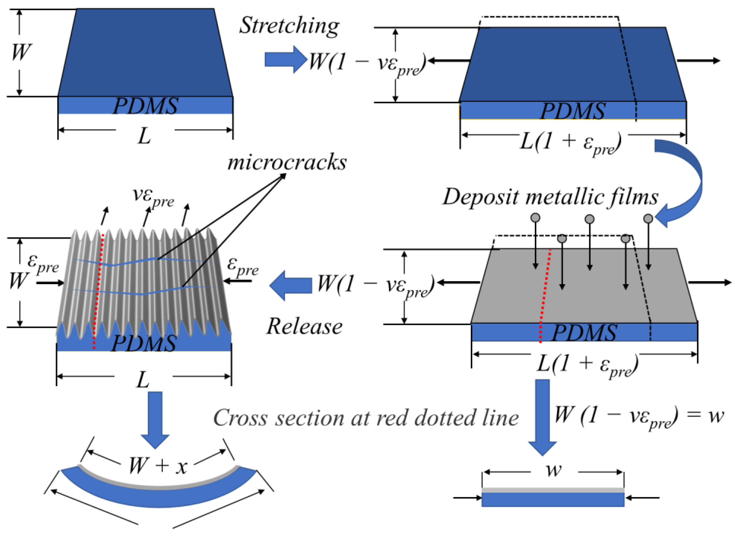
Figure 1. Schematic diagram of microcrack formation in wrinkled metallic thin films prepared by the prestrain method; the transverse strain leads to the formation of microcracks after releasing the prestrain.
Metals 11 00427 g001
Figure 2. (a) Optical image of microcracks in 30% prestrain CoFeB film. (b) AFM image of a microcrack in 30% prestrain CoFeB film. (c) Pt film with 10% prestrain, the film is curved. (d) Film in Figure 2c after being flattened. (e) Optical image of Pt film with 10% prestrain, no microcrack. (f) Optical image of flatten film in Figure 2d, many microcracks appear.
Metals 11 00427 g002
Figure 3. (a) For the convenience of calculation, the bending film is equivalent to the flattened film; w is the width of the substrate under prestrain, w + x is the width of the film after releasing the prestrain, W is the width of the lower surface of the substrate after releasing the prestrain. (b) Strain variation of substrate from the top surface to bottom surface; d is the thickness of the substrate. (c) Optical image of bent film under vertical light source. (d) Schematic representation of the bright and dark areas of the film. (e) The relationship between the width of bright areas and the curvature radius of thin films; L is the width of the bright area of the curved film, R is the corresponding curvature radius.
Metals 11 00427 g003
Figure 4. (a) Poisson’s ratio (ν) of polydimethylsiloxane (PDMS) substrate is calculated by measuring the change of marker width on PDMS when releasing prestrain. (b) PDMS substrate Poisson’s ratio test results: the red point is the experimental data, the green curve is the theoretical fitting value when ν = 0.4. (c) PDMS tensile curve; when the tensile amount is 0–50%, the Young’s modulus is 1.14 MPa by fitting, and the red curve is the theoretical fitting. (d) The mechanical properties of the Ta/CoFeB/Ta thin films are calculated by measuring the strain of the film during the tensile process.
Metals 11 00427 g004
Figure 5. (a) Strain of different materials (25 nm thickness) on PDMS after releasing the prestrain as a function of the prestrain. (b) Radius of curvature of different materials (25 nm thickness) on PDMS as a function of the prestrain. The line is the theoretical value, and the point is the experimental value.
Metals 11 00427 g005
Figure 6. Ta (2.5 nm)/CoFeB (20 nm)/Ta (2.5 nm) film. (a) The cross-section of the prestrain strip film. (b) Analysis of single strip film. (c) Strain of 100 μm strip films with different spacing under different prestrains. (d) Strain of blank substrates with different widths under different prestrains. The lines are the theoretical values and the points are the experimental values.
Metals 11 00427 g006
Table 1. Comparison of experimental and theoretical values of transverse strain of blank strip substrate in Figure 6d.
Blank Strip Substrate Width (μm)Prestrain (%)Experiment Strain (%)Theory Strain (%)
13511.18.2 ± 0.38.0
19.314.8 ± 1.314.5
26.019.9 ± 0.820.0
18011.17.3 ± 0.57.2
19.213.9 ± 1.112.8
26.019.4 ± 1.817.9
36.425 ± 0.526.3
27012.557.3 ± 0.47.6
20.013.2 ± 0.512.7
24.915.9 ± 0.216.1
34.122.4 ± 0.323.0
36012.17.2 ± 0.16.6
20.111.5 ± 0.311.3
31.018.3 ± 0.818.2
36.820.8 ± 0.222.2
Publisher’s Note: MDPI stays neutral with regard to jurisdictional claims in published maps and institutional affiliations.