Article

On the High-Temperature Oxidation and Area Specific Resistance of New Commercial Ferritic Stainless Steels

Department of Chemistry and Industrial Chemistry (DCCI), University of Genoa, Via Dodecaneso 31, 16146 Genoa, Italy
*
Author to whom correspondence should be addressed.
Metals 2021, 11(3), 405; https://doi.org/10.3390/met11030405
Submission received: 29 January 2021 / Revised: 17 February 2021 / Accepted: 22 February 2021 / Published: 1 March 2021
(This article belongs to the Special Issue High-Temperature Corrosion and Protection of Alloys)

Abstract

:
Two commercial ferritic stainless steels (FSSs), referred to as Steel A and Steel B, designed for specific high-temperature applications, were tested in static air for 2000 h at 750 °C to evaluate their potential as base materials for interconnects (ICs) in Intermediate Temperature Solid Oxide Fuel Cell stacks (IT-SOFCs). Their oxidation behavior was studied through weight gain and Area Specific Resistance (ASR) measurements. Additionally, the oxide scales developed on their surfaces were characterized by X-ray Diffraction (XRD), Micro-Raman Spectroscopy (μ-RS), Scanning Electron Microscopy, and Energy Dispersive X-ray Fluorescence Spectroscopy (SEM-EDS). The evolution of oxide composition, structure, and electrical conductivity in response to aging was determined. Comparing the results with those on AISI 441 FSS, steels A and B showed a comparable weight gain but higher ASR values that are required by the application. According to the authors, Steel A and B compositions need an adjustment (i.e., a plain substitution of the elements which form insulant oxides or a marginal modification in their content) to form a thermally grown oxide (TGO) with the acceptable ASR level.

1. Introduction

Interconnects (ICs) are key elements of Intermediate Temperature-Solid Oxide Fuel Cells (IT-SOFCs), i.e., electrochemical devices made of an array of units which directly convert, in the temperature range from 650 °C to 850 °C, the chemical energy of a fuel (i.e., hydrogen or other fuels) into electrical energy [1,2,3,4,5]. This system offers many advantages over traditional energy conversion devices as: high efficiency, reliability, modularity, fuel adaptability, low noise, and very low levels of NOx and SOx emissions [6,7,8,9].
In planar stack design, the vital tasks of ICs are: to guarantee the electrical connection between the anode of one individual cell to the cathode of the neighboring one in order to accumulate voltage output (in fact, a single IT-SOFC, which is typically constituted by a dense electrolyte placed between two porous electrodes, produces around 1 V open circuit potential), to serve as barriers physically separating the reducing (anode side) from the oxidizing (cathode side) atmosphere, and to act as a support structure for the cells [10,11,12].
For more than a decade, ICs have been mainly made of ferritic stainless steels (FSSs). In fact, after the successful reduction of SOFC operation temperature in the range 650 °C to 850 °C, this class of materials was selected among others (e.g., chromium-based alloys and Ni-Cr based alloys) to replace LaCrO3-based interconnects since it exhibits adequate application characteristics: a thermal expansion coefficient (TEC) similar to the other ceramic parts of the fuel cell (11.5–14.0 × 10⁻⁶/K from RT to 800 °C), good thermal and electrical conductivity, good manufacturability and mechanical properties, easy fabricability, affordable cost and, in the case of chromia-former steels containing over 16 wt.% Cr, the formation of a comparatively conductive and protective Cr2O3 scale in presence of an oxidizing atmosphere [13,14,15].
Under IT-SOFC operating conditions and for a planned service of thousands of hours (≃40,000), FSSs interconnects show, however, some limitations: an inadequate oxidation resistance which determines a drop in metallic interconnect (MIC) stability and electrical conductivity; the formation and migration of volatile Cr(VI) species (e.g., CrO3 and Cr(OH)2O2) from ICs into the cathode where they form, after reduction at the three-phase boundary (TPB), Cr2O3 [13,16,17,18,19]. Cr poisoning, whose mechanism and kinetics have been extensively studied [20,21,22,23], represents one of the main disadvantages to the use of chromia-forming MIC since this phenomenon causes a drastic reduction of cell performances.
Several solutions have been proposed with the aim of solving the aforementioned issues, particularly for the oxidizing environment of the cathode side, such as: the design of alloys with specific compositions (e.g., Crofer 22 H, Crofer 22 APU, Sanergy HT, or ZMG 232 [24,25,26,27,28]), the application of surface treatments (e.g., polishing and grinding) and/or modifications in the alloy microstructure [29,30,31], and the production and application of protective coatings (e.g., reactive element oxides, conductive perovskites, conductive spinels, and conductive composite spinels [8,12]). Generally, protective coatings made of transition metal spinels show good stability and adhesion to metal substrate and, in comparison with rare-earth perovskites ones, a better ability to inhibit chromium diffusion [32]. Among these groups of compounds, Mn-Cu spinels have a higher electrical conductivity at high temperatures (e.g., Mn1.7Cu1.3O4 about 225 S cm−1 at 750 °C) and lower cost than the more studied Mn-Co spinels; for this reason, the formers are recently receiving more attention [16,32,33].
During the evaluation of a FSS as a candidate for SOFC interconnects, the attention is usually focused on the study of its electrical conductivity (i.e., the acceptable Area Specific Resistance, ASR, level is considered to be below 0.1 Ωcm2), oxidation resistance, and Cr volatilization under SOFC operating conditions; the composition and morphology of the oxide scale growing on its surface are even analyzed since all the aforementioned properties strongly depend on them [8,34,35].
The aim of this work was the study of two commercial FSSs, hereafter referred to as Steel A and Steel B, as a possible candidate for IC in IT-SOFCs stacks. These materials have been originally designed for the manufacture of exhaust manifolds and their composition, in particular the presence of copper as an alloying element [36], drew our attention for the reasons explained below.
The study and then the use of commercial FSSs as base material for IC in IT-SOFCs stacks is not a novelty, as it is represented by the case of FSSs AISI 441 and AISI 444 [37,38,39,40,41,42]. Since the manufacture of MIC represents about 45% of the overall stack production costs, the use of this group of FSSs can guarantee a reduction of those costs, even when further actions, e.g., the application of protective coatings, are needed [43].
In order to compare the oxidation kinetics of Steel A and Steel B, their oxidation behavior was investigated by means of weight gain measurement during aging for 2000 h in static air at 750 °C. The oxide scales developed on their surfaces were then analyzed through different techniques (i.e., ASR measurements, Scanning Electron Microscopy and Energy Dispersive X-ray Fluorescence Spectroscopy (SEM-EDS), X-ray Diffraction (XRD), and Micro-Raman Spectroscopy, (μ-RS)) with the aim of determining their composition, structure, electrical conductivity, and, with specific reference to Cu, the element response to aging. The last information was useful to understand Cu influence on the oxidation resistance of both investigated FSSs, to hypothesize its role in the presence of protective coatings with specific composition, e.g., the above-mentioned manganese-copper spinel oxide, and, finally, to evaluate the steel capability of forming a Cu-based spinel itself.

2. Materials and Methods

2.1. Materials

All the investigated samples, approximatively 10 mm × 10 mm × 1.5 mm sized, were mechanically cut from two “as-rolled” sheets of FSSs named, respectively, Steel A and Steel B. Their nominal compositions are shown in Table 1 [36].
These compositions have been specifically developed for high-temperature applications, i.e., for the manufacture of automotive exhaust manifolds [36].
During the evaluation of FSSs as materials for IT-SOFC applications, their oxidation resistance is a property of major interest. In addition, the MIC performances depend upon other characteristics as the composition and the value of conductivity of the oxide scale grown on their surface. This information was determined during this study.

2.2. Weight Gain Measurements

For weight gain measurements of Steel A and Steel B, five sets of samples each made up of five rectangular coupons were aged, after ultrasonic cleaning with distilled water and then ethanol, at 750 °C in a muffle furnace (Lenton, Fairland, South Africa), in static air up to 2000 h.
For each aging time (i.e., 100, 200, 750, 1000, and 2000 h), one set was extracted after slow cooling in a furnace to avoid spallation and scaling of the oxide layer, while the others continued the thermal treatment. Once they reached room temperature, the five samples were kept in a desiccator before being weighed with a Mettler Toledo AE 240 Analytical Balance (Mettler Toledo, Columbus, OH, USA) (readability of 0.01 mg with ±0.03 mg linearity and reproducibility of 0.02 mg). The weight change corresponds to the difference between the final weight and the one measured right before the thermal treatment. The weight change data were normalized to sample surface area and reported in mg/cm2. After the weight change measurement, part of these samples was subjected to ASR measurements, as detailed in the following paragraph.

2.3. Area Specific Resistance Measurements

This study included the evaluation of ASR, whose value expresses the electrical resistance of the metallic interconnects [5].
ASR can be expressed as follows [35]:
A S R = 2 ρ 0 l 0 ,
where ρ0 and l0 represent, respectively, the resistivity and the thickness of the oxide scale.
The measuring of ASR was complicated by a number of issues, particularly contacting problems [44] and, to avoid them, the system used during this study consisted of a four poles circuit with gold meshes in direct contact with the two faces of the sample; each mesh was welded to two gold wires and mechanically pressed on the sample surfaces to further ensure the contact (Figure 1).
The ASR measurements were performed at 750 °C and in static air using a custom test bench on pre-aged samples coming from the weight gain measurements. Once verified the homogenous weight growth in the batch of five samples aged for the same amount of time, only one of them was selected as representative for the ASR measurements. In order to ensure consistency in the measurement, the sample aged for 100 h was excluded from ASR tests, this because the thermally grown oxide (TGO) had completed, at this stage, the first step of formation [42].
The evaluation of the electrical performances was carried out using a VSP galvanostat/potentiostat (Biologic, Seyssinet-Pariset, France) once the sample reached the planned temperature and included the following steps:
  • galvanostatic Electrochemical Impedance Spectroscopy (EIS) at 500 μA in the frequency range between 600 KHz–200 mHz;
  • repetition of the measurement every five hours until the measured resistance was stable.
The measured electrical resistance was determined by fitting the EIS spectra using a resistive element. ASR, expressed in Ωcm2, was then calculated by multiplying this resistance by the contact area (in this case 1 cm2) and dividing by two in order to consider the contribution of a single oxide scale formed on the sample.

2.4. Cross-Sections Preparation and Chemical and Morphological Characterization

The study of the chemical and morphological peculiarities of the TGOs formed on Steel A and Steel B concerned the surfaces and cross-sections of two samples aged, after careful ultrasonic cleaning with distilled water and then ethanol, for 1000 h at 750 °C in a muffle furnace.
For cross-sections preparation, these aged samples were cut, part of them cold-mounted in epoxy resin, and then polished according to the metallographic standard procedure ASTM E 3_95 up to 1 μm diamond suspension.
The surfaces and cross-sections were then characterized by means of:
  • SEM through a ZEISS EVO 40 SEM (Carl Zeiss, Oberkochen, Germany)
    SEM micrographs, showing the morphology of the oxide scales and the elements distribution, were obtained using 20 kV of acceleration voltage, a working distance of 12 mm, and the secondary electrons (SE) detector;
  • XRD with a Philips X’Pert 1 diffractometer (Malvern Pananalytical, Malvern, UK) with Bragg–Brentano geometry
    XRD data were collected using 40 kV of acceleration voltage, a current of 30 mA, and the CuKα radiation (λ = 1.5406 Å); diffractograms were recorded from 15 to 80° 2θ, in 0.0250° 2θ increments with 5.0 s counting time per increment;
  • μ-RS with a Jasco NRS-4100 spectrometer (Jasco, Easton, MD, USA)
    μ-RS spectra were acquired using a green laser (λ = 532 nm); the samples were observed with a 20× or 100× objective and exposed to a laser beam with a power from 0.7 to 7 mW at the sample surface. The Raman spectrometer was operated using continuous scanning mode in the spectral window from 100 to 4000 cm−1.

3. Results

3.1. Weight Gain and ASR Measurements

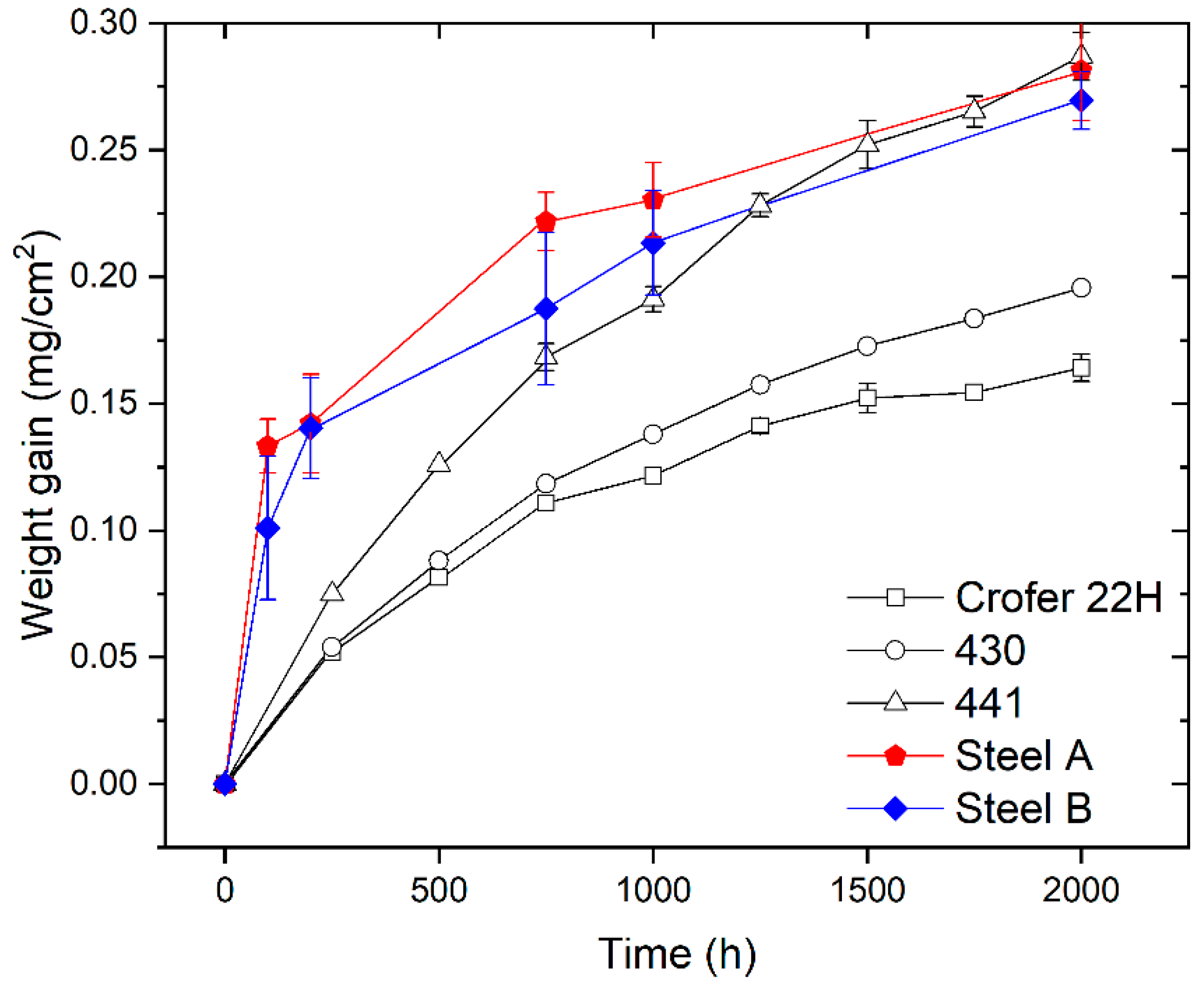
Figure 2 shows the weight gain of Steels A and B measured after ageing in static air at 750 °C for different oxidation times (i.e., 100, 200, 750, 1000, and 2000 h) compared with the weight gain data published in literature and concerning the FSSs commonly used for stack manufacturing [45].
The weight gain of the investigated steels increases with time (Figure 2). This means that the oxide scale growth is the dominant process and spallation of the oxide scale was not noticed. This last observation confirms the results of specific tests published elsewhere [36].
According to curves of Figure 2, Steel B exhibits slightly lower values of weight gain compared with Steel A. However, both are close to the behavior of AISI 441 FSS which is considered a standard material to produce ICs for IT-SOFC stacks [46].
The shape of weight gain curves of Steel A and B is similar (Figure 2) and indicates that their oxidation kinetics follows the parabolic rate law. This suggests that the rate-determining factor is the outward diffusion of cations (e.g., Cr, Mn, etc.) and/or inward diffusion of the oxygen anion through the growing oxide scale [34]. For these steels, the parabolic oxidation rate constant (Kp) in terms of the weight change was evaluated by the equation:
( Δ W A ) 2 = K p t ,
where ΔW is the weight gain (g), A is the sample surface area (cm2), and t is the oxidation time (s). The experimentally obtained Kp for Steel A and Steel B are in the range of values found in literature (Table 2) [45]. Specifically, they are slightly lower than the Kp of AISI 441.
Graphs of Figure 3 report the results of ASR measurements on Steel A and Steel B in the function of the aging process compared with the weight gain.
The ASR values of the two FSSs are comparable, even though Steel A generally shows lower ASR values than those measured for Steel B. The only exception is represented by the value of ASR measured at 1000 h (0.18 Ωcm2 and 0.15 Ωcm2 for Steel A and B, respectively). Steel A evidences a mismatch of the growth between ASR and weight gain in the first 1000 h (Figure 3a) while steel B seems to have a higher coherency between the weight gain and the ASR trend (Figure 3b).
As shown by Equation (1), ASR expresses the electrical resistance of the metallic interconnects depending on the scale thickness and the resistivity, which is constant if the chemical composition of the oxide scale is not variable. Therefore, in the initial process of scale formation, it is coherent to have a mismatch between the ASR growth and the weight gain. If such differences persist, other hypotheses might be used to explain the phenomenon as, for instance, the formation of new layers (e.g., Si or Al oxides at the interface TGO/metal substrate), the diffusion of elements other than Cr and Mn into the TGO (e.g., Fe, Ti), or the interaction of the TGO with the surrounding atmosphere (e.g., Cr evaporation) [47].

3.2. Chemical and Morphological Characterization of Surfaces and Cross-Sections
The surfaces and cross-sections of samples were investigated, after aging for 1000 h, through SEM-EDS in order to study and measure both the morphology and the elemental composition of the TGOs covering the FSSs-based substrates.
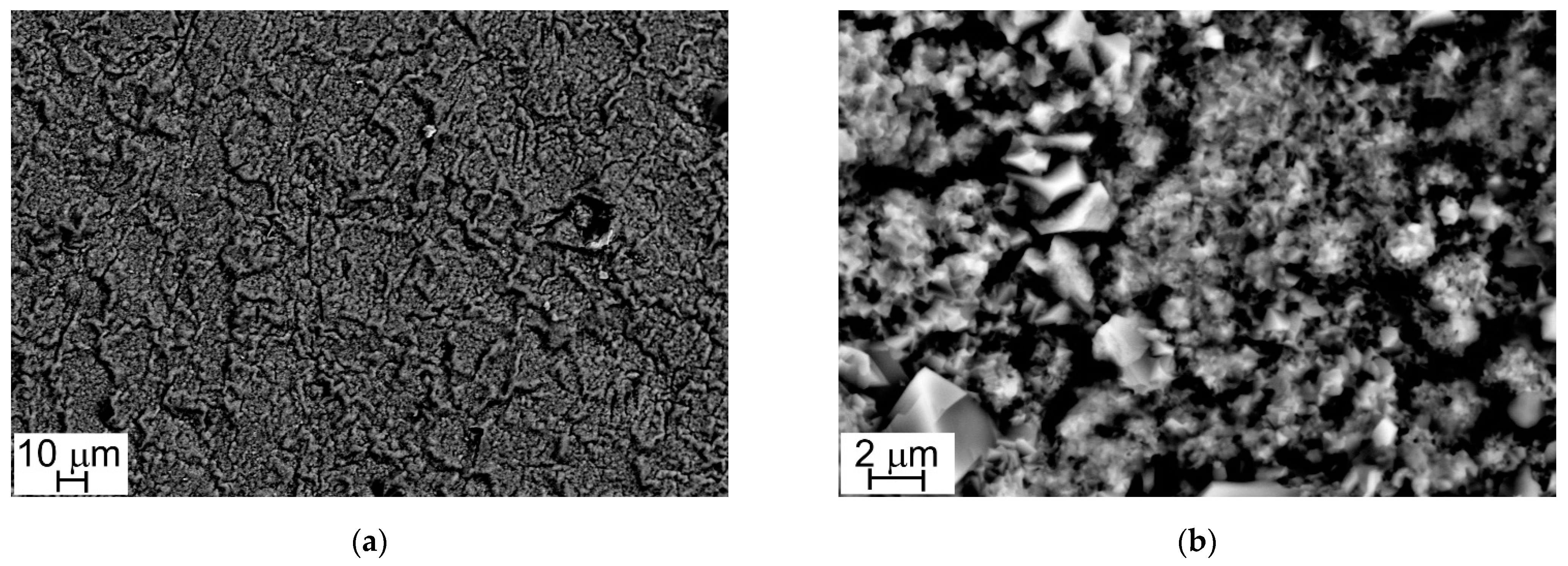
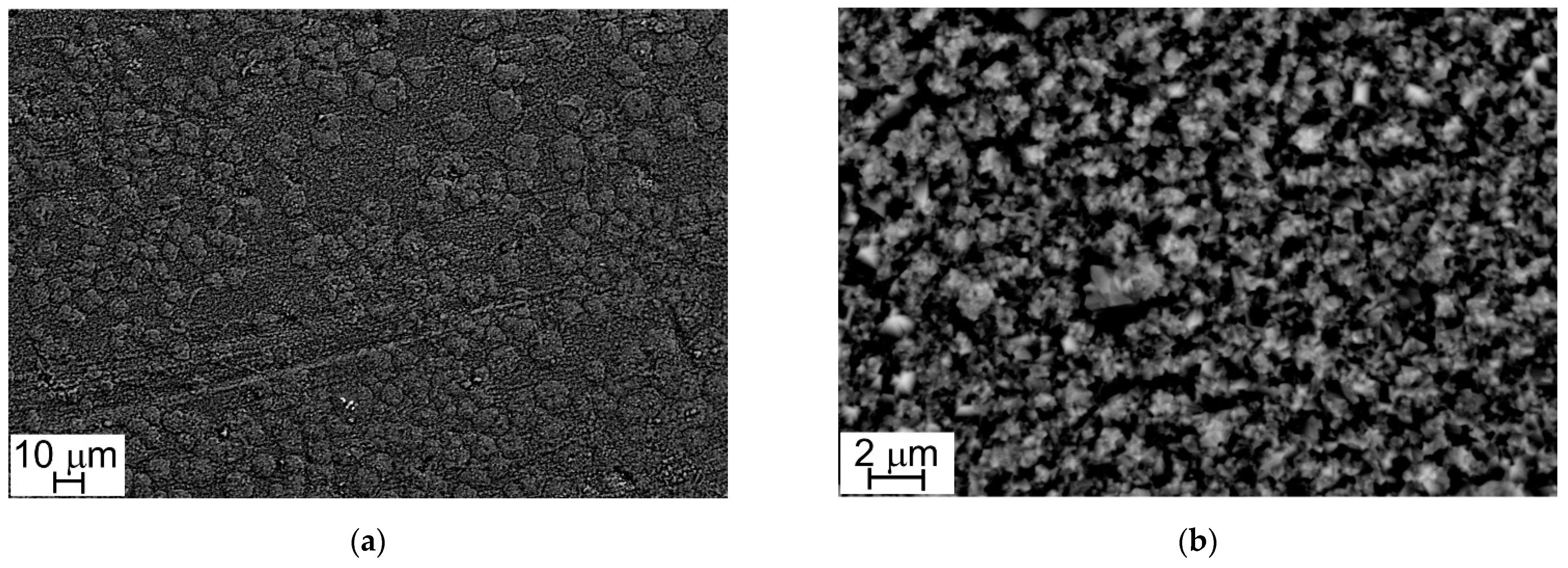
Figure 4 and Figure 5 show the oxide layers grown on Steel A and Steel B surfaces at different magnifications.
At low magnification (1000×), sample surfaces show a similar appearance: they are completely covered with oxide crystals alternating in small and large sizes (Figure 4a and Figure 5a). This peculiarity is more evident at higher magnification (10,000×) and especially in the case of Steel A (Figure 4b).
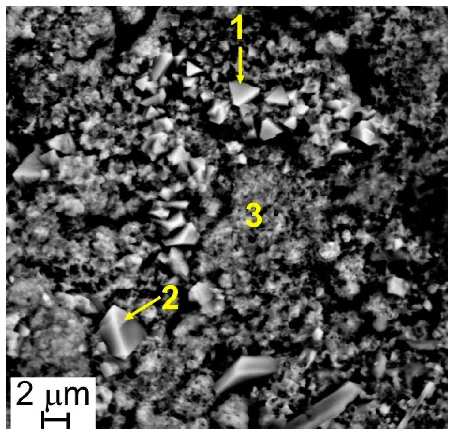
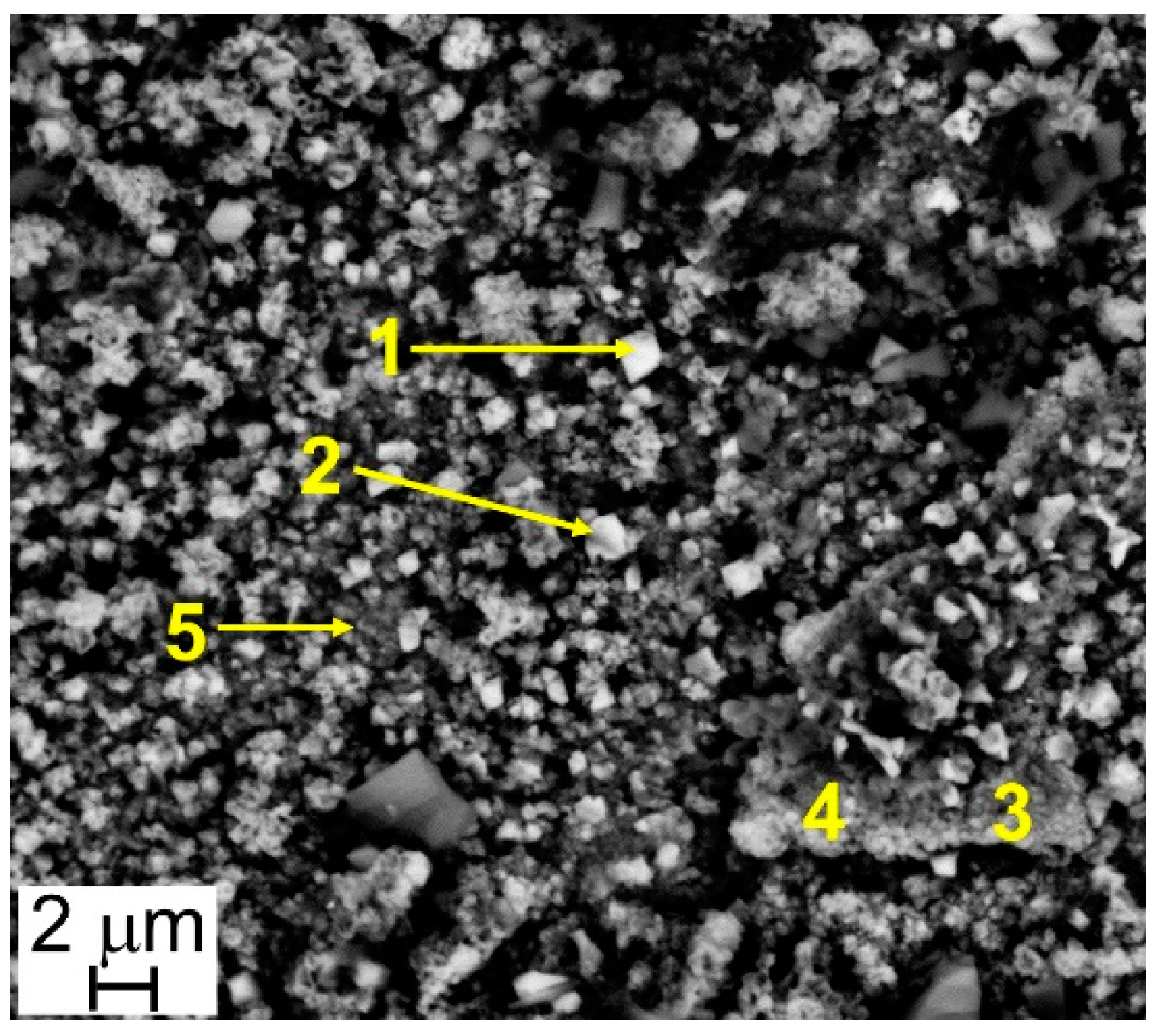
The results of EDS analyses indicate that all the investigated surfaces are mainly constituted by Cr, Mn, Fe, and O and that the easily recognizable well-facet surface crystals of large size are characterized by a higher amount of Mn than the smaller ones (Table 3 and Table 4, Figure 6 and Figure 7). Other elements were clearly detected but in very low concentrations (Table 3 and Table 4): Al, Si, and Cu for Steel A and B, Ti for Steel B only. It is important to highlight that, on surfaces of both samples, and especially on that of Steel A, the presence of Cu, at first sight, seems to come along with higher Mn concentrations and lower Cr and Fe concentrations (Table 3 and Table 4), confirming the higher diffusion rate of Cu compared to the one of Cr in the oxide scale [48].
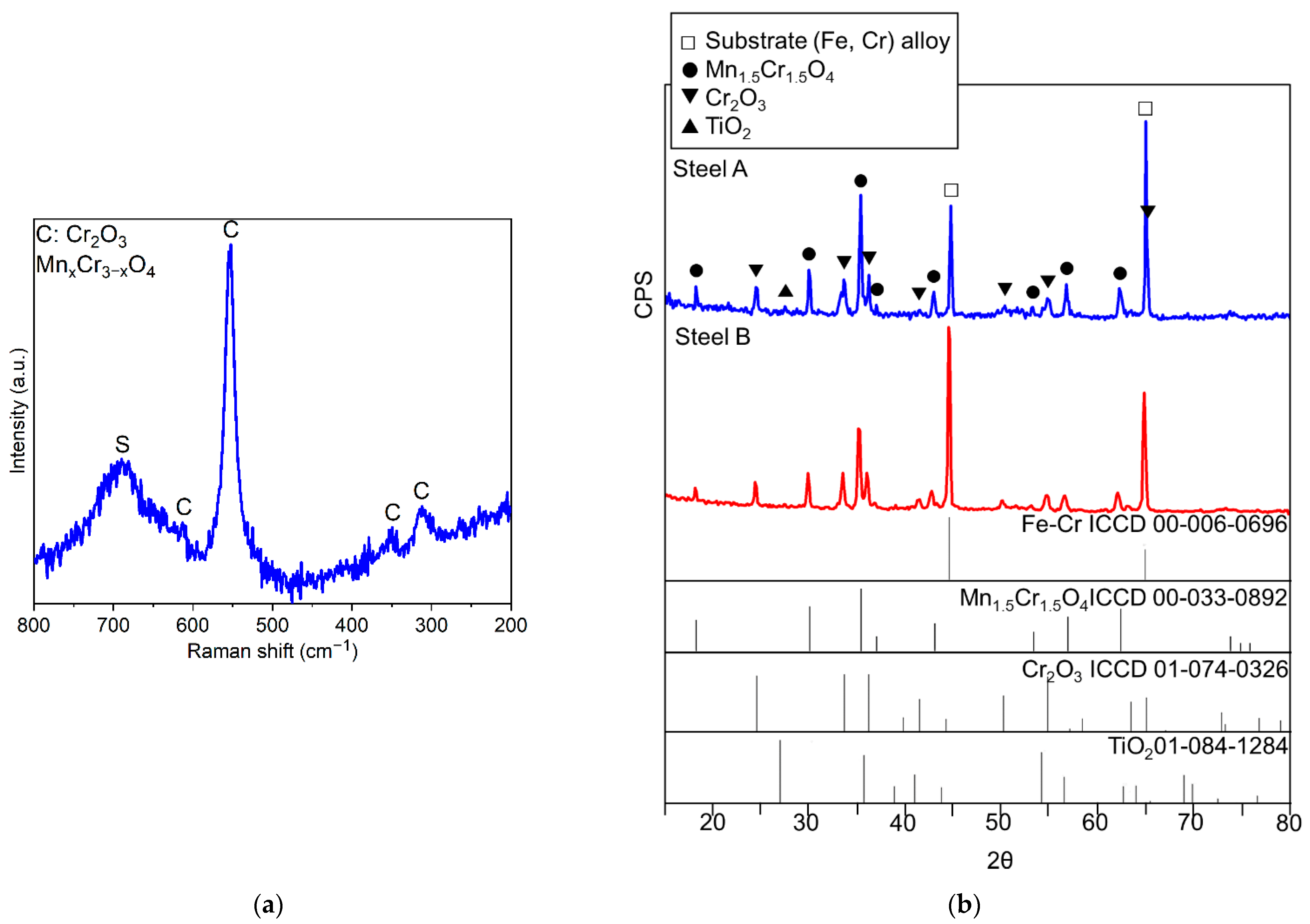
The nature of the oxides forming the scale was defined by surface techniques as μ-RS and XRD. In the case of μ-RS analyses, it was also possible to gather spectra from the cross-sections of the specimens. In Table 5, a list of the identified compounds is presented and representative examples of the collected experimental μ-RS spectra and diffractograms are shown in Figure 8.
Figure 8. Experimental Raman spectrum of the oxide scale grown on Steel A with the indication of compounds identified through comparison with literature [49,50,51] (a) and experimental diffractograms, Steel A and Steel B (b)
Metals 11 00405 g008
It is worth noting that all diffractograms show the peaks of the metallic substrate (Fe-Cr alloy) since the X-rays reached the FSS due to the limited thickness of the oxide scale (Figure 8b).
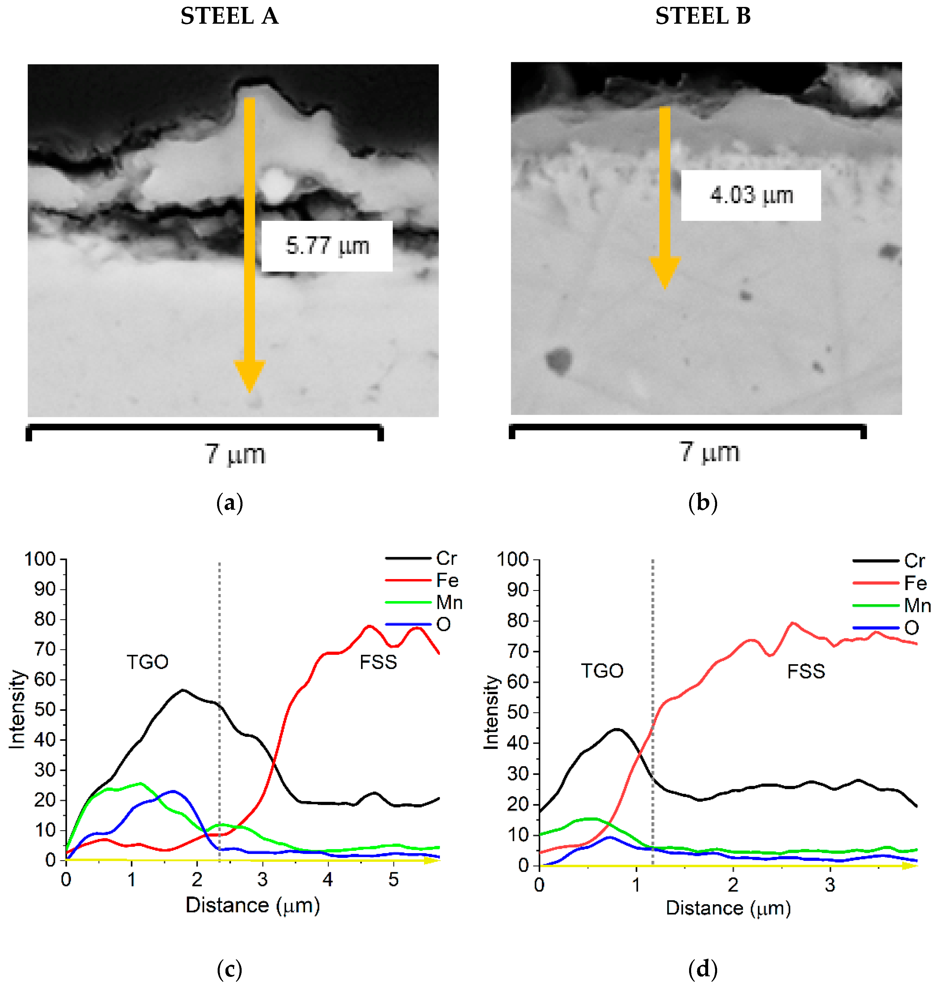
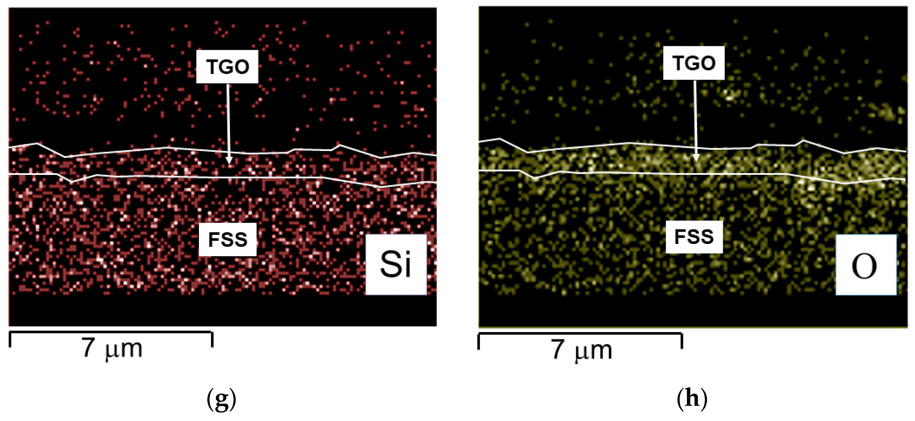
The EDS semi-quantitative profiles of elements (Figure 9c,d) performed along sample cross-sections (yellow arrows in Figure 9a,b) allow for observing that the distribution of Fe, Mn, Cr, and O elements is similar for both FSSs.
Cr is mainly concentrated at the interface TGO/metallic substrate forming the inner layer of chromia while the external layer, mainly made of spinel oxide, contains a higher amount of Mn. The presence of Cu and of the other minor elements was too low to be expressed in this graph. A quantitative profile was then acquired to better highlight such detail and the results are presented in Figure 10 and Figure 11.
The cross-section of Steel A shows that:
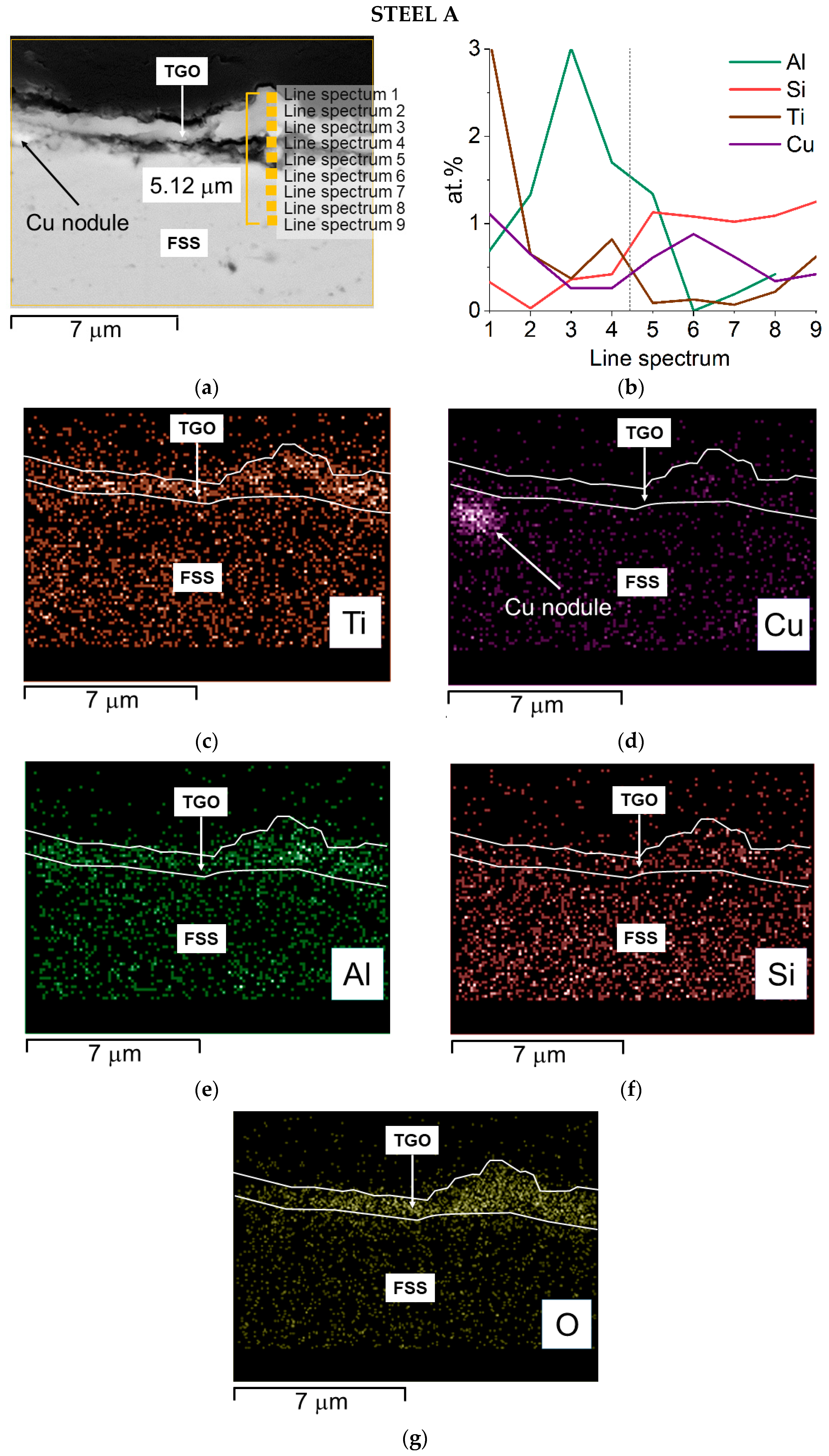
  • Cu segregates at the interface TGO/FSS in the form of small nodules (Figure 10d) and diffuses at the top of the spinel layer where Mn is higher than Cr (Figure 10b);
  • Ti has two zones of concentration, the first, smaller, is at the interface between the scale and the metal substrate, the second and major one, is at the external part of the TGO (Figure 10b,c);
  • Al shows a maximum concentration in the inner layer of the oxide scale (Figure 10b,e)
  • Si is primarily distributed inside the alloy and forms a thin layer just before the first peak of Ti (Figure 10b,f).
The cross-section of Steel B shows that:
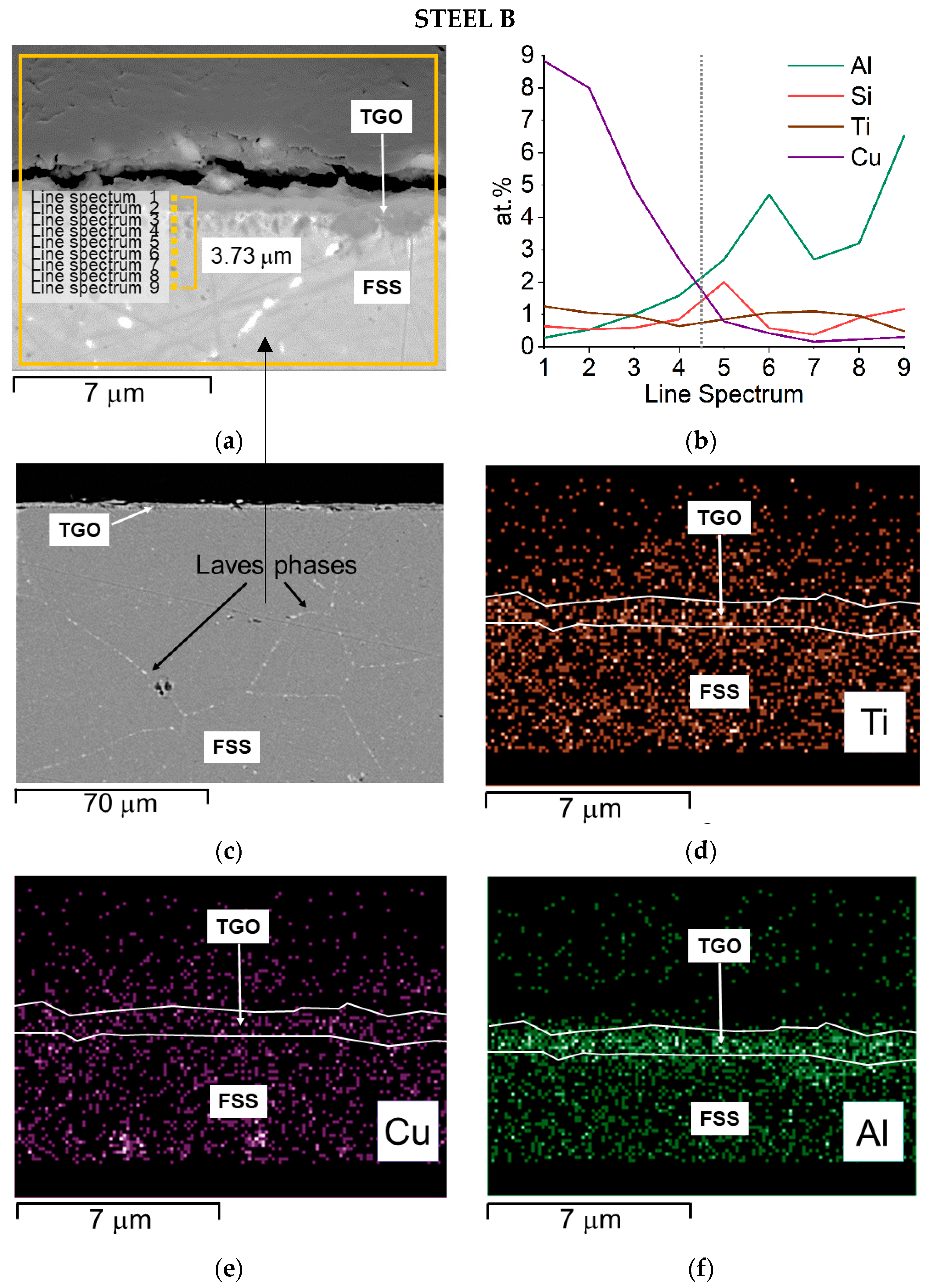
  • Cu segregates in the form of small nodules inside the alloy (Figure 11e) and, according to the EDS quantitative profile, its concentration grows, moving from the alloy to the external part of the TGO where it reaches the highest value (Figure 11b);
  • Ti and particularly Al seem to be more concentrated at the interface TGO/FSS according to the EDS map and the EDS quantitative profile, respectively (Figure 11d,b); for Al, the EDS map also shows the element distribution inside the TGO and at the metal substrate edge where Al rich oxides are precipitating within the matrix (Figure 11f);
  • Si shows a peak of concentration at the interface TGO/FSS (Figure 11b) even if EDS maps suggest, for this element, a homogeneous distribution inside the alloy (Figure 11g).
The composition of the alloy after aging, and especially the variation in the content of Cr, Mn, and Cu, was measured. The results of the EDS quantitative profile on Steel A and B performed at spots indicated in Figure 10a and Figure 11a, respectively, are listed in Table 6 and Table 7. For Steel A, they show that: Cr content is around 13 wt.% from the edge to 3 μm deep in the bulk, Cu in this same area is below 1.2 wt.% ranging around 0.5 wt.%, and Mn is below 0.5 wt.%. Alloying elements’ depletion is detectable and strong, especially for Mn. For Cu, we can estimate that at the interface metal substrate/TGO, more than half of the Cu is diffusing inside the oxide, while for Cr, this corresponds to 5–8 wt.%.
Steel B starts from a higher Cr content (Table 1) and, in the alloy nearby the interface with the TGO, this is around 16 wt.% (Table 7). Mn shows a concentration in the alloy below 0.5 wt.% rising up to higher content at the direct interface with the TGO where it grows to up 27 wt.% in the spinel crystal (Table 7). Cu is around 1 wt.% until the substrate/TGO interface and reaches 5 wt.% in the outer oxide layer (Table 7), highlighting a clear diffusion process from the metal substrate to the TGO.

4. Discussion

The slightly lower weight gain values observed for Steel B and confirmed by the calculated Kp value are attributed to the different composition of the two steels (Table 1) and, specifically, to the presence, in Steel B, of Mo, and Nb, in addition to a larger Cr content. This element offers a higher resistance to high-temperature oxidation, whereas Mo and Nb contribute to control the diffusion of elements at the alloy grain boundaries by forming Laves phases [9,52,53].
Steels A and B have shown a weight gain comparable with AISI 441, with Steel A and Steel B displaying slightly lower values than AISI 441 FSS at 2000 h (i.e., 0.28 mg/cm2–0.27 mg/cm2–0.29 mg/cm2, respectively). A reduced weight gain is related to the amount of absorbed oxygen to form the TGO but is also connected with the evaporation phenomena due to the further oxidation of CrIII oxides into CrVI volatile compounds [54,55,56].
The detection, on both samples, of oxide scales made of an inner Cr2O3-based layer and an outer Mn-Cr mixed oxide layer, is extensively documented in the case of FSSs containing Cr from 16 to 25 wt.% and small amount of Mn (i.e., <1 wt.%) [25,54,56,57,58,59,60,61,62].
The growth and positioning of Mn-Cr mixed oxide at the external part of the oxide scale, even if the Mn content in the alloy is low, depend upon various factors: the low solubility of Mn in chromia, the fast diffusivity of Mn ions through chromia (i.e., manganese diffuses, apparently via lattice rather than grain boundaries, two orders of magnitude faster than chromium in Cr2O3 scales), the stability of Mn-Cr spinel with respect to the binary oxides, i.e., Cr2O3 and MnO, at high temperatures [58,63,64]. Sabioni et al. [65] compared the diffusion coefficients of various elements into the chromia in function of the temperature, confirming that Mn (3.3 × 10⁻¹⁷ cm2/s) diffuses faster than Fe (1.7 × 10⁻¹⁸ cm2/s) and Cr (4.6 × 10⁻¹⁸ cm2/s) at 800 °C. Copper also diffuses into the chromia, sustaining the formation of a spinel where it concentrates [66].
The presence of an outer Mn-Cr spinel layer has advantageous effects: it improves the overall scale electrical conductivity because its resistivity is lower than that of Cr2O3; it limits Cr evaporation phenomenon since the formation of Cr(VI) volatile compounds from the spinel is from one to two orders of magnitude lower than from the chromia, with a linear Cr vaporization versus time; when it is capable to form a continuous layer, it is an effective barrier to oxygen diffusion, and this can increase considerably the oxidation resistance [58,67,68,69,70,71,72,73,74].
SEM-EDS analyses performed on sample surfaces seem to indicate a moderate contribution of copper to the TGOs’ formation (Table 3 and Table 4). Its participation in the spinel formation is suggested by the absence of specific Cu-oxidized compounds. A limited amount of Cu can in fact dissolve inside the spinel lattice, due to the affinity with Mn. According to Talic et al. [75] the presence of Cu affects the Cr self-diffusion by increasing it and therefore enhances the formation of the spinel layer. This may result in a reduced content of Fe and Cr within the oxide layers, as effectively observed (Table 3 and Table 4), and hence in the positive effect of lowering the formation of Cr-rich volatile compounds. Mn-based spinels containing Cu are known to be highly stable [76] and are used as protective coating on MICs [77,78]. It is hence consistent to consider the presence, inside Steel A and B, of Cu in concentration as high as 1.2 wt.% as an element increasing the stability of the TGO also toward the evaporation process.
Further research activities are, however, planned to measure the evaporation rate of the three steels (i.e., 441, A, and B) to better understand the chemical stability of the oxide part of the TGO.
In addition, EDS elemental maps show that Cu as well segregates, as small nodules, at the TGO/FSS interface (Steel A, Figure 10d) and within the alloy at the grain boundaries where Laves phases are also present (Steel B, Figure 11c,e). According to [13,34] the largest concentration of this element at the TGO/FSS interface (Steel A, Figure 10d), enhance the oxidation resistance since the segregated Cu acts as a diffusion barrier for both the anions and cations.
So far, beside the correspondence of the weight gain rate of the three steels, the measured ASR values, i.e., 0.20 Ωcm2 for Steel A and 0.21 Ωcm2 for Steel B, are both indeed higher than the one required by the application (i.e., smaller than 0.1 Ωcm2 after 40,000 h at operating conditions [79]). This can only be correlated to the presence of elements as Si and Al forming tiny but highly resistive oxides (Al2O3 conductivity ~10−9 S/cm at 750 °C [80] and SiO2 conductivity ~0.4 × 10⁻⁶ S/cm at 750 °C [81]) at the interface alloy/oxide scale [8,12,82,83]. The presence of Al-rich oxides is suggested by EDS maps (Figure 10e,g and Figure 11f,h). Nevertheless, neither Al2O3 nor SiO2 were identified by XRD, confirming their very limited volume fraction.
In the case of Steel A, the results of SEM-EDS and XRD analyses indicate the presence of an external and not continuous TiO2 layer, which can serve as a barrier to Cr evaporation reaction [84]. Generally, in fact, addition of an adequate amount of Ti improves the Cr evaporation resistance as well as the electrical properties of the oxide scale and the oxidation resistance of the FSSs [52,84].
Investigations by means of Focused Ion Beam-High Resolution SEM (FIB-HRSEM) will be carried out to better understand the nature and formation of the oxides and of their interfaces with the FSS substrates.
Based on data collected during this research activity, Steels A and B have a weight gain rate comparable with the state-of-the-art FSS in use as interconnects of SOFC stacks, but need an improvement (possibly a plain substitution of some elements such as Si and Al or a marginal modification in their content) to form a TGO with an ASR matching with the SOFC application. Moreover, the performances of the studied FSSs in IT-SOFC applications could be further improved through the deposition of protective and electrically conductive coatings [85,86,87,88]. In such a case, the presence of Cu in the stainless steel might play an important role to strengthen the adhesion between the metal substrate and Mn-Cu spinel oxide.

5. Conclusions

This paper explored the oxidation behavior at 750 °C of two commercial FSSs, referred to as Steel A and Steel B, in order to establish their potential as interconnects for IT-SOFCs stacks. The thermally grown oxide has been studied and characterized through weight gain measurements, ASR measurements, and spectroscopic analyses (i.e., XRD, μ-RS, SEM-EDS), on the surfaces and the cross-sections. The samples were aged for various ranges of time using air as oxidizing atmosphere. The analyses showed the oxide growth rate, the distribution of elements diffusing from the metal substrate into the TGO, and the overall electrical resistance of the metal/oxide system. The main conclusions are:
  • Steel A and Steel B have a similar oxidation behavior compatible with that of AISI 441 FSS, which is a standard material used as IC for IT-SOFC. Steel B exhibits slightly lower values of weight gain compared with Steel A. Such difference could be explained by the presence, in Steel B, of adequate amounts of Nb and Mo in addition to a larger Cr content. This element offers a higher resistance to high-temperature oxidation, whereas Mo and Nb contribute to control the diffusion of elements at the alloy grain boundaries by forming Laves phases;
  • All samples are characterized by TGOs mainly consisting of an inner Cr2O3 subscale and an outer Cu-doped (Mn,Cr)3O4 spinel layer. The presence of a discontinuous TiO2 scale, that can serve as a barrier to Cr evaporation reaction, was observed in steel A;
  • The ASR values measured on both steels are higher than those typical of suitable FSS for ICs. Such a result could be explained by the presence of elements such as Al and Si, which form resistive oxides mainly disposed at the alloy/TGO interface.
  • Compositional improvements of the studied steels are required for their application as ICs in SOFC stacks. In particular, the substitution or the adjustment of Si and Al content is necessary to enhance the electrical conductivity of the TGO.
Further investigations will be carried out to better understand the nature of the oxides, their mechanism of formation, and the applicability of protective coatings on these steels.

Author Contributions

Conceptualization, V.B. and P.P.; methodology, V.B., P.P. and R.S.; validation, V.B., R.S. and P.P.; formal analysis, V.B. and D.P.; investigation, V.B., P.P. and D.P.; resources, P.P. and R.S.; data curation, V.B., P.P. and D.P.; writing—original draft preparation, V.B. and P.P.; writing—review and editing, V.B., P.P. and R.S.; visualization, V.B., P.P. and R.S.; supervision, P.P.; project administration, P.P.; funding acquisition, P.P. All authors have read and agreed to the published version of the manuscript.

Funding

This research was funded by the European Union’s Seventh Framework Program (FP7/2007-2013) Fuel Cells and Hydrogen Joint Undertaking (FCH-JU-2013-1) under Grant Agreement No. 621207.

Institutional Review Board Statement

Not applicable.

Informed Consent Statement

Not applicable.

Acknowledgments

The steels have been kindly provided by Nippon Steel and Sumikin Stainless Steel Corporation (Tokyo, Japan). The authors thank Roberto Lo Savio, Luca Repetto, and Pavlo Solokha for performing μ-RS and XRD analyses.

Conflicts of Interest

The authors declare no conflict of interest. The funders had no role in the design of the study; in the collection, analyses, or interpretation of data; in the writing of the manuscript, or in the decision to publish the results.

References

  1. Shri Prakash, B.; Pavitra, R.; Senthil Kumar, S.; Aruna, S.T. Electrolyte bi-layering strategy to improve the performance of an intermediate temperature solid oxide fuel cell: A review. J. Power Sources 2018, 381, 136–155. [Google Scholar] [CrossRef]
  2. Da Silva, F.S.; De Souza, T.M. Novel materials for solid oxide fuel cell technologies: A literature review. Int. J. Hydrogen Energy 2017, 42, 26020–26036. [Google Scholar] [CrossRef] [Green Version]
  3. Aruna, S.T.; Balaji, L.S.; Senthil Kumar, S.; Shri Prakash, B. Electrospinning in solid oxide fuel Cells—A review. Renew. Sustain. Energy Rev. 2017, 67, 673–682. [Google Scholar] [CrossRef]
  4. Mahmud, L.S.; Muchtar, A.; Somalu, M.R. Challenges in fabricating planar solid oxide fuel cells: A review. Renew. Sustain. Energy Rev. 2017, 72, 105–116. [Google Scholar] [CrossRef]
  5. Li, J.; Zhang, W.; Yang, J.; Yan, D.; Pu, J.; Chi, B.; Jian, L. Oxidation behavior of metallic interconnect in solid oxide fuel cell stack. J. Power Sources 2017, 353, 195–201. [Google Scholar] [CrossRef]
  6. Niewolak, L.; Tietz, F.; Quadakkers, W.J. Interconnects. In High-Temperature Solid Oxide Fuel Cells for the 21st Century Fundamentals, Design and Applications, 2nd ed.; Kendall, K., Kendall, M., Eds.; Elsevier: London, UK, 2016; pp. 195–254. [Google Scholar]
  7. Ravi Chandran, P.; Arjunan, T.V. A review of materials used for solid oxide fuel cell. Int. J. Chem. Technol. Res. 2015, 7, 488–497. [Google Scholar]
  8. Mahato, N.; Banerjee, A.; Gupta, A.; Omar, S.; Balani, K. Progress in material selection for solid oxide fuel cell technology: A review. Prog. Mater. Sci. 2015, 72, 141–337. [Google Scholar] [CrossRef]
  9. Safikhani, A.; Esmailian, M.; Tinatiseresht, T.; Barati Darband, G. High temperature cyclic oxidation behavior of ferritic stainless steel with addition of alloying elements Nb and Ti for use in SOFCs interconnect. Int. J. Hydrogen Energy 2016, 41, 6045–6052. [Google Scholar] [CrossRef]
  10. Öztürk, B.; Topcu, A.; Öztürk, S.; Cora, Ö.N. Oxidation, electrical and mechanical properties of Crofer®22 solid oxide fuel cell metallic interconnects manufactured through powder metallurgy. Int. J. Hydrogen Energy 2018, 43, 10822–10833. [Google Scholar] [CrossRef]
  11. Qi, Q.; Wang, L.; Liu, Y.; Huang, Z. Oxidation resistance optimization of TiC/hastelloy composites by adding Ta element applied for intermediate temperature solid oxide fuel cell interconnects. J. Power Sources 2018, 401, 1–5. [Google Scholar] [CrossRef]
  12. Mah, J.C.W.; Muchtara, A.; Somalu, M.R.; Ghazali, M.J. Metallic interconnects for solid oxide fuel cell: A review on protective coating and deposition techniques. Int. J. Hydrogen Energy 2017, 42, 9219–9229. [Google Scholar] [CrossRef]
  13. Swaminathan, S.; Ko, Y.S.; Lee, Y.-S.; Kim, D.-I. Oxidation behavior and area specific resistance of La, Cu and B alloyed Fe-22Cr ferritic steels for solid oxide fuel cell interconnects. J. Power Sources 2017, 369, 13–26. [Google Scholar] [CrossRef]
  14. Lenka, R.K.; Patro, P.K.; Sharma, J.; Mahat, T.; Sinha, P.K. Evaluation of La0.75Sr0.25Cr0.5Mn0.5O3 protective coating on ferritic stainless steel interconnect for SOFC application. Int. J. Hydrogen Energy 2016, 41, 20365–20372. [Google Scholar] [CrossRef]
  15. Ryter, J.; Amendola, R.; McCleary, M.; Shong, W.-J.; Liu, C.-K.; Spotorno, R.; Piccardo, P. Effect of electrical current on the oxidation behavior of electroless nickel-plated ferritic stainless steel in solid oxide fuel cell operating conditions. Int. J. Hydrogen Energy 2018, 43, 426–434. [Google Scholar] [CrossRef]
  16. Wang, R.; Sun, Z.; Pal, U.B.; Gopalan, S.; Basu, S.N. Mitigation of chromium poisoning of cathodes in solid oxide fuel cells employing CuMn1.8O4 spinel coating on metallic interconnect. J. Power Sources 2018, 376, 100–110. [Google Scholar] [CrossRef]
  17. Kim, B.K.; Kim, D.-I.; Yi, K.-W. Suppression of Cr evaporation by Co electroplating and underlying Cr retention mechanisms for the 22 wt.% Cr containing ferritic stainless steel. Corros. Sci. 2018, 130, 45–55. [Google Scholar] [CrossRef]
  18. Piccardo, P.; Pecunia, A.; Bongiorno, V.; Spotorno, R.; Wuillemin, Z.; Ouweltjes, J.P. Ageing of materials at inlet and outlet fuel manifolds in a SOFC stack. ECS Trans. 2015, 68, 2611–2624. [Google Scholar] [CrossRef]
  19. Spotorno, R.; Piccardo, P.; Schiller, G. Effect of cathode contacting on anode supported cell performances. J. Electrochem. Soc. 2016, 163, F872–F876. [Google Scholar] [CrossRef] [Green Version]
  20. Zhang, X.; Yu, G.; Zeng, S.; Parbey, J.; Xiao, S.; Li, B.; Lia, T.; Andersson, M. Mechanism of chromium poisoning the conventional cathode material for solid oxide fuel cells. J. Power Sources 2018, 381, 26–29. [Google Scholar] [CrossRef]
  21. Jiang, S.P.; Chen, X. Chromium deposition and poisoning of cathodes of solid oxide fuel Cells—A review. Int. J. Hydrogen Energy 2014, 39, 505–531. [Google Scholar] [CrossRef]
  22. Yang, Z.; Guo, M.; Wang, N.; Ma, C.; Wang, J.; Han, M. A short review of cathode poisoning and corrosion in solid oxide fuel cell. Int. J. Hydrogen Energy 2017, 42, 24948–24959. [Google Scholar] [CrossRef]
  23. Amezawa, K.; Shindo, Y.; Fujimaki, Y.; Kimura, Y.; Nakamura, T.; Iguchi, F.; Yashiro, K.; Yugami, H.; Kawada, T. Mechanism of chromium poisoning in SOFC cathode investigated by using pattern thin film model electrode. ECS Trans. 2017, 78, 965–970. [Google Scholar] [CrossRef]
  24. Park, M.; Shin, J.-S.; Lee, S.; Kim, H.-J.; An, H.; Ji, H.-I.; Kim, H.; Son, J.-W.; Lee, J.-H.; Kim, B.-K.; et al. Thermal degradation mechanism of ferritic alloy (Crofer 22 APU). Corros. Sci. 2018, 134, 17–22. [Google Scholar] [CrossRef]
  25. Sachitanand, R.; Sattari, M.; Svensson, J.-E.; Froitzheim, J. Evaluation of the oxidation and Cr evaporation properties of selected FeCr alloys used as SOFC interconnects. Int. J. Hydrogen Energy 2013, 38, 15328–15334. [Google Scholar] [CrossRef] [Green Version]
  26. Talic, B.; Molin, S.; Hendriksen, P.V.; Lein, H.L. Effect of pre-oxidation on the oxidation resistance of Crofer 22 APU. Corros. Sci. 2018, 138, 189–199. [Google Scholar] [CrossRef] [Green Version]
  27. Bredvei Skilbred, A.W.; Haugsrud, R. The effect of dual atmosphere conditions on the corrosion of Sandvik sanergy HT. Int. J. Hydrogen Energy 2012, 37, 8095–8101. [Google Scholar] [CrossRef]
  28. Hosseini, N.; Karimzadeh, F.; Abbasi, M.H.; Choi, G.M. Correlation between microstructure and electrical properties of Cu1.3Mn1.7O4/La2O3 composite-coated ferritic stainless steel interconnects. J. Alloys Compd. 2016, 673, 249–257. [Google Scholar] [CrossRef]
  29. Cooper, L.; Benhaddad, S.; Wood, A.; Iveya, D.G. The effect of surface treatment on the oxidation of ferritic stainless steels used for solid oxide fuel cell interconnects. J. Power Sources 2008, 184, 220–228. [Google Scholar] [CrossRef]
  30. Bongiorno, V.; Piccardo, P.; Anelli, S.; Spotorno, R. Influence of surface finishing on high-temperature oxidation of AISI type 444 ferritic stainless steel used in SOFC stacks. Acta Metall. Sin. Engl. 2017, 30, 697–711. [Google Scholar] [CrossRef]
  31. Belogolovsky, I.; Hou, P.Y.; Jacobson, C.P.; Visco, S.J. Chromia scale adhesion on 430 stainless steel: Effect of different surface treatments. J. Power Sources 2008, 182, 259–264. [Google Scholar] [CrossRef]
  32. Ranjbar-Nouri, Z.; Soltanieh, M.; Rastegari, S. Applying the protective CuMn2O4 spinel coating on AISI-430 ferritic stainless steel used as solid oxide fuel cell interconnects. Surf. Coat. Technol. 2018, 334, 365–372. [Google Scholar] [CrossRef]
  33. Waluyo, N.S.; Park, S.-S.; Song, R.-H.; Lee, S.-B.; Lim, T.-H.; Hong, J.-E.; Ryu, K.H.; Im, W.B.; Lee, J.-W. Protective coating based on manganese–copper oxide for solid oxide fuel cell interconnects: Plasma spray coating and performance evaluation. Ceram. Int. 2018, 44, 11576–11581. [Google Scholar] [CrossRef]
  34. Swaminathan, S.; Lee, Y.-S.; Kim, D.-I. Effects of alloyed La, Cu and B on the oxidation of Fe-22Cr ferritic stainless steels under simulated cathode side atmosphere of solid oxide fuel cell interconnects. Corros. Sci. 2018, 133, 150–164. [Google Scholar] [CrossRef]
  35. Zhu, W.Z.; Deevi, S.C. Opportunity of metallic interconnects for solid oxide fuel cells: A status on contact resistance. Mater. Res. Bull. 2003, 38, 957–973. [Google Scholar] [CrossRef]
  36. Hamada, J.I.; Kanno, N.; Hayashi, A.; Hiraide, N.; Abe, M.; Nishimura, K.; Takushima, C.; Yakawa, A.; Fudanoki, F. Development of new ferritic stainless steel sheets with excellent heat resistance and formability for automotive exhaust manifolds. Metall. Ital. 2018, 5, 33–39. [Google Scholar]
  37. Goebel, C.; Alnegren, P.; Faust, R.; Svensson, J.-E.; Froitzheim, J. The effect of pre-oxidation parameters on the corrosion behavior of AISI 441 in dual atmosphere. Int. J. Hydrogen Energy 2018, 43, 14665–14674. [Google Scholar] [CrossRef]
  38. Sabato, A.G.; Chrysanthou, A.; Salvo, M.; Cempura, G.; Smeacetto, F. Interface stability between bare, MnCo spinel coated AISI 441 stainless steel and a diopside-based glass-ceramic sealant. Int. J. Hydrogen Energy 2018, 43, 1824–1834. [Google Scholar] [CrossRef] [Green Version]
  39. Alnegren, P.; Sattari, M.; Svensson, J.-E.; Froitzheim, J. Severe dual atmosphere effect at 600 °C for stainless steel 441. J. Power Sources 2016, 301, 170–178. [Google Scholar] [CrossRef] [Green Version]
  40. Kumar, V.; Kaur, G.; Lu, K.; Pickrell, G. Interfacial compatibility of alumino-borosilicate glass sealants with AISI 441 and YSZ for different atmospheres. Int. J. Hydrogen Energy 2015, 40, 1195–1202. [Google Scholar] [CrossRef]
  41. Lee, K.; Yoon, B.; Kang, J.; Lee, S.; Bae, J. Evaluation of Ag-Doped (MnCo)3O4 spinel as a solid oxide fuel cell metallic interconnect coating material. Int. J. Hydrogen Energy 2017, 42, 29511–29517. [Google Scholar] [CrossRef]
  42. Piccardo, P.; Anelli, S.; Bongiorno, V.; Spotorno, R.; Repetto, L.; Girardon, P. K44M ferritic stainless steel as possible interconnect material for SOFC stack operating at 600 °C: Characterization of the oxidation behavior at early working stages. Int. J. Hydrogen Energy 2015, 40, 3726–3738. [Google Scholar] [CrossRef]
  43. Grolig, J.G.; Froitzheim, J.; Svensson, J.E. Coated stainless steel 441 as interconnect material for solid oxide fuel cells: Oxidation performance and chromium evaporation. J. Power Sources 2014, 248, 1007–1013. [Google Scholar] [CrossRef] [Green Version]
  44. Grolig, J.G.; Froitzheim, J.; Svensson, J.E. Coated stainless steel 441 as interconnect material for solid oxide fuel cells: Evolution of electrical properties. J. Power Sources 2015, 284, 321–327. [Google Scholar] [CrossRef] [Green Version]
  45. Talic, B.; Venkatachalam, V.; Hendriksen, P.V.; Kiebach, R. Comparison of MnCo2O4 coated crofer 22 H, 441, 430 as interconnects for intermediate-temperature solid oxide fuel cell stacks. J. Alloys Compd. 2020, 821, 153229–153240. [Google Scholar] [CrossRef]
  46. Bianco, M.; Ouweltjes, J.P.; Van Herle, J. Degradation analysis of commercial interconnect materials for solid oxide fuel cells in stacks operated up to 18,000 h. Int. J. Hydrogen Energy 2019, 44, 31406–31422. [Google Scholar] [CrossRef]
  47. Spotorno, R. High-Temperature oxidation of AISI441 ferritic stainless steel for solid oxide fuel cells. Mater. Sci. Forum 2021, 1016, 1381–1385. [Google Scholar] [CrossRef]
  48. Niu, Y.; Gesmundo, F.; Viani, F.; Douglass, D.L. The air oxidation of two phase Cu-Cr alloys at 200–900 °C. Oxid. Met. 1997, 48, 357–380. [Google Scholar] [CrossRef]
  49. Madern, N.; Monnier, J.; Baddour-Hadjean, R.; Steckmeyer, A.; Joubert, J.-M. Characterization of refractory steel oxidation at high temperature. Corros. Sci. 2018, 132, 223–233. [Google Scholar] [CrossRef]
  50. Hosterman, B.D. Raman Spectroscopic Study of Solid Solution Spinel Oxides. Ph.D. Thesis, University of Nevada, Las Vegas, NV, USA, 2011. [Google Scholar]
  51. Srisrual, A.; Coindeau, S.; Galerie, A.; Petit, J.-P.; Wouters, Y. Identification by photoelectrochemistry of oxide phases grown during the initial stages of thermal oxidation of AISI 441 ferritic stainless steel in air or in water vapour. Corros. Sci. 2009, 51, 562–568. [Google Scholar] [CrossRef]
  52. Safikhani, A.; Esmailian, M.; Salmani, M.R.; Aminfard, M. Effect of Ni-Mo addition on cyclic and isothermal oxidation resistance and electrical behavior of ferritic stainless steel for SOFCs interconnect. Int. J. Hydrogen Energy 2014, 39, 11210–11223. [Google Scholar] [CrossRef]
  53. Horita, T.; Kishimoto, H.; Yamaji, K.; Xiong, Y.; Sakai, N.; Brito, M.E.; Yokokawa, H. Evaluation of laves-phase forming Fe-Cr alloy for SOFC interconnects in reducing atmosphere. J. Power Sources 2008, 176, 54–61. [Google Scholar] [CrossRef]
  54. Key, C.; Eziashi, J.; Froitzheim, J.; Amendola, R.; Smith, R.; Gannon, P. Methods to quantify reactive chromium vaporization from solid oxide fuel cell interconnects. J. Electrochem. Soc. 2014, 161, C373–C381. [Google Scholar] [CrossRef] [Green Version]
  55. Rufner, J.; Gannon, P.; White, P.; Deibert, M.; Teintze, S.; Smith, R.; Chen, H. Oxidation behavior of stainless steel 430 and 441 at 800 °C in single (air/air) and dual atmosphere (air/hydrogen) exposures. Int. J. Hydrogen Energy 2008, 33, 1392–1398. [Google Scholar] [CrossRef]
  56. Falk-Windisch, H.; Svensson, J.E.; Froitzheim, J. The effect of temperature on chromium vaporization and oxide scale growth on interconnect steels for solid oxide fuel cells. J. Power Sources 2015, 287, 25–35. [Google Scholar] [CrossRef] [Green Version]
  57. Tucker, M.C. Progress in metal-supported solid oxide fuel cells: A review. J. Power Sources 2010, 195, 4570–4582. [Google Scholar] [CrossRef]
  58. Hua, B.; Kong, Y.; Zhang, W.; Pu, J.; Chi, B.; Jian, L. The effect of Mn on the oxidation behavior and electrical conductivity of Fe-17Cr alloys in solid oxide fuel cell cathode atmosphere. J. Power Sources 2011, 196, 7627–7638. [Google Scholar] [CrossRef]
  59. Niewolak, L.; Wessel, E.; Singheiser, L.; Quadakkers, W.J. Potential suitability of ferritic and austenitic steels as interconnect materials for solid oxide fuel cells operating at 600 °C. J. Power Sources 2010, 195, 7600–7608. [Google Scholar] [CrossRef]
  60. Swaminathan, S.; Lee, Y.-S.; Kim, D.-I. Long term high temperature oxidation characteristics of La and Cu alloyed ferritic stainless steels for solid oxide fuel cell interconnects. J. Power Sources 2016, 327, 104–118. [Google Scholar] [CrossRef]
  61. Magdefrau, N.J.; Chen, L.; Sun, E.Y.; Aindow, M. Effects of alloy heat treatment on oxidation kinetics and scale morphology for Crofer 22 APU. J. Power Sources 2013, 241, 756–767. [Google Scholar] [CrossRef]
  62. Yamamura, K.; Uehara, T.; Tanaka, S.; Yasuda, N. Oxidation behavior of Fe-Cr ferritic alloy for SOFC interconnects ZMG232G10 in air and H2/H2O. ECS Trans. 2013, 57, 2177–2186. [Google Scholar] [CrossRef]
  63. Young, D.J. High Temperature Oxidation and Corrosion of Metals, 1st ed.; Elsevier: Oxford, UK, 2008; pp. 350–351. [Google Scholar]
  64. Lobnig, R.E.; Schmidt, H.P.; Hennesen, K.; Grabke, H.J. Diffusion of cations in chromia layers grown on iron-base alloys. Oxid. Met. 1992, 37, 81–93. [Google Scholar] [CrossRef]
  65. Sabioni, A.C.S.; Huntz, A.M.; Borges, L.C.; Jomard, F. First study of manganese diffusion in Cr2O3 polycrystals and thin films by SIMS. Philos. Mag. 2007, 87, 1921–1937. [Google Scholar] [CrossRef] [Green Version]
  66. Dileep Kumar, C.J.; Dekich, A.; Wang, H.; Liu, Y.; Tilson, W.; Ganley, J.; Fergus, J.W. Transition metal doping of manganese cobalt spinel oxides for coating SOFC interconnects. J. Electrochem. Soc. 2014, 161, F47–F53. [Google Scholar] [CrossRef]
  67. Yang, Z.; Hardy, J.S.; Walker, M.S.; Xia, G.; Simner, S.P.; Stevenson, J.W. Structure and conductivity of thermally grown scales on ferritic Fe-Cr-Mn steel for SOFC interconnect applications. J. Electrochem. Soc. 2004, 151, A1825–A1831. [Google Scholar] [CrossRef]
  68. Fontana, S.; Amendola, R.; Chevalier, S.; Piccardo, P.; Caboche, G.; Viviani, M.; Molins, R.; Sennour, M. Metallic interconnects for SOFC: Characterisation of corrosion resistance and conductivity evaluation at operating temperature of differently coated alloys. J. Power Sources 2007, 171, 652–662. [Google Scholar] [CrossRef]
  69. Yang, Z.; Xia, G.G.; Li, X.H.; Stevenson, J.W. (Mn,Co)3O4 spinel coatings on ferritic stainless steels for SOFC interconnect applications. Int. J. Hydrogen Energy 2007, 32, 3648–3654. [Google Scholar] [CrossRef]
  70. Holcomb, G.R. Calculation of reactive-evaporation rates of chromia. Oxid. Met. 2008, 69, 163–180. [Google Scholar] [CrossRef] [Green Version]
  71. Holcomb, G.R.; Alman, D.E. The effect of manganese additions on the reactive evaporation of chromium in Ni-Cr alloys. Scr. Mater. 2006, 54, 1821–1825. [Google Scholar] [CrossRef] [Green Version]
  72. Stanislowski, M.; Froitzheim, J.; Niewolak, L.; Quadakkers, W.J.; Hilpert, K.; Markus, T.; Singheiser, L. Reduction of chromium vaporization from SOFC interconnectors by highly effective coatings. J. Power Sources 2007, 164, 578–589. [Google Scholar] [CrossRef]
  73. Grabke, H.J.; Muller-Lorenz, E.M.; Strauss, S.; Pippel, E.; Woltersdorf, J. Effects of grain size, cold working, and surface finish on the metal-dusting resistance of steels. Oxid. Met. 1998, 50, 241–254. [Google Scholar] [CrossRef]
  74. Paravidino, D.; Piccardo, P.; Spotorno, R. A novel method for evaluation of chromium evaporation from solid oxide fuel cells interconnects: A feasibility study. Mater. Sci. Forum 2021, 1016, 1109–1113. [Google Scholar] [CrossRef]
  75. Talic, B.; Vang Hendriksen, P.; Wiik, K.; Lein, H.L. Diffusion couple study of the interaction between Cr2O3 and MnCo2O4 doped with Fe and Cu. Solid State Ion. 2019, 332, 16–24. [Google Scholar] [CrossRef]
  76. Vandenberghe, R.E.; Robbrecht, G.G.; Brabers, V.A.M. On the stability of the cubic spinel structure in the system Cu-Mn-O. Mater. Res. Bull. 1973, 8, 571–579. [Google Scholar] [CrossRef]
  77. Sun, Z.; Wang, R.; Nikiforov, A.Y.; Gopalan, S.; Pal, U.B.; Basu, S.N. CuMn1.8O4 protective coatings on metallic interconnects for prevention of Cr-poisoning in solid oxide fuel cells. J. Power Sources 2018, 378, 125–133. [Google Scholar] [CrossRef]
  78. Sun, Z.; Gopalan, S.; Pal, U.B.; Basu, S.N. Electrophoretically deposited copper manganese spinel coatings for prevention of chromium poisoning in solid oxide fuel cells. In Energy Technology 2019—Carbon Dioxide Management and Other Technologies, Proceedings of the Energy Technologies Symposium, San Antonio, TX, USA, 10–14 March 2019; Wang, T., Chen, X., Guillen, D.P., Zhang, L., Sun, Z., Wang, C., Haque, N., Howarter, J.A., Neelameggham, N.R., Ikhmayies, S., et al., Eds.; Springer: Cham, Switzerland, 2019; pp. 265–272. [Google Scholar]
  79. Jian, P.; Jian, L.; Bing, H.; Ie, G. Oxidation kinetics and phase evolution of a Fe-16Cr alloy in simulated SOFC cathode atmosphere. J. Power Sources 2006, 158, 354–360. [Google Scholar] [CrossRef]
  80. Öijerholm, J.; Pan, J.; Leygraf, C. In-Situ measurements by impedance spectroscopy of highly resistive α-alumina. Corros. Sci. 2006, 48, 243–257. [Google Scholar] [CrossRef]
  81. Shackelford, J.F.; Alexander, W. Electrical properties of materials. In CRC Material Science and Engineering Handbook, 3rd ed.; CRC Press: Boca Raton, FL, USA, 2001; Chapter 7. [Google Scholar]
  82. Wu, J.; Liu, X. Recent development of SOFC metallic interconnect. J. Mater. Sci. Technol. 2001, 26, 293–305. [Google Scholar] [CrossRef]
  83. Hua, B.; Pu, J.; Lu, F.; Zhang, J.; Chi, B.; Jian, L. Development of a Fe-Cr alloy for interconnect application in intermediate temperature solid oxide fuel cells. J. Power Sources 2010, 195, 2782–2788. [Google Scholar] [CrossRef]
  84. Seo, H.S.; Yun, D.W.; Kim, K.Y. Effect of Ti addition on the electric and ionic property of the oxide scale formed on the ferritic stainless steel for SOFC interconnect. Int. J. Hydrogen Energy 2012, 37, 16151–16160. [Google Scholar] [CrossRef]
  85. Shaigan, N.; Qu, W.; Ivey, D.G.; Chen, W. A review of recent progress in coatings, surface modifications and alloy developments for solid oxide fuel cell ferritic stainless steel interconnects. J. Power Sources 2010, 195, 1529–1542. [Google Scholar] [CrossRef]
  86. Hu, Y.Z.; Yao, S.W.; Li, C.X.; Li, C.J.; Zhang, S.L. Influence of pre-reduction on microstructure homogeneity and electrical properties of APS Mn1.5Co1.5O4 coatings for SOFC interconnects. Int. J. Hydrogen Energy 2017, 42, 27241–27253. [Google Scholar] [CrossRef]
  87. You, P.F.; Zhang, X.; Zhang, H.L.; Liu, H.J.; Zeng, C.L. Effect of CeO2 on oxidation and electrical behaviors of ferritic stainless steel interconnects with Ni-Fe coatings. Int. J. Hydrogen Energy 2018, 43, 7492–7500. [Google Scholar] [CrossRef]
  88. Xu, Z.; Xu, W.; Stephens, E.; Koeppel, B. Mechanical reliability and life prediction of coated metallic interconnects within solid oxide fuel cells. Renew. Energy 2017, 13, 1472–1479. [Google Scholar] [CrossRef]
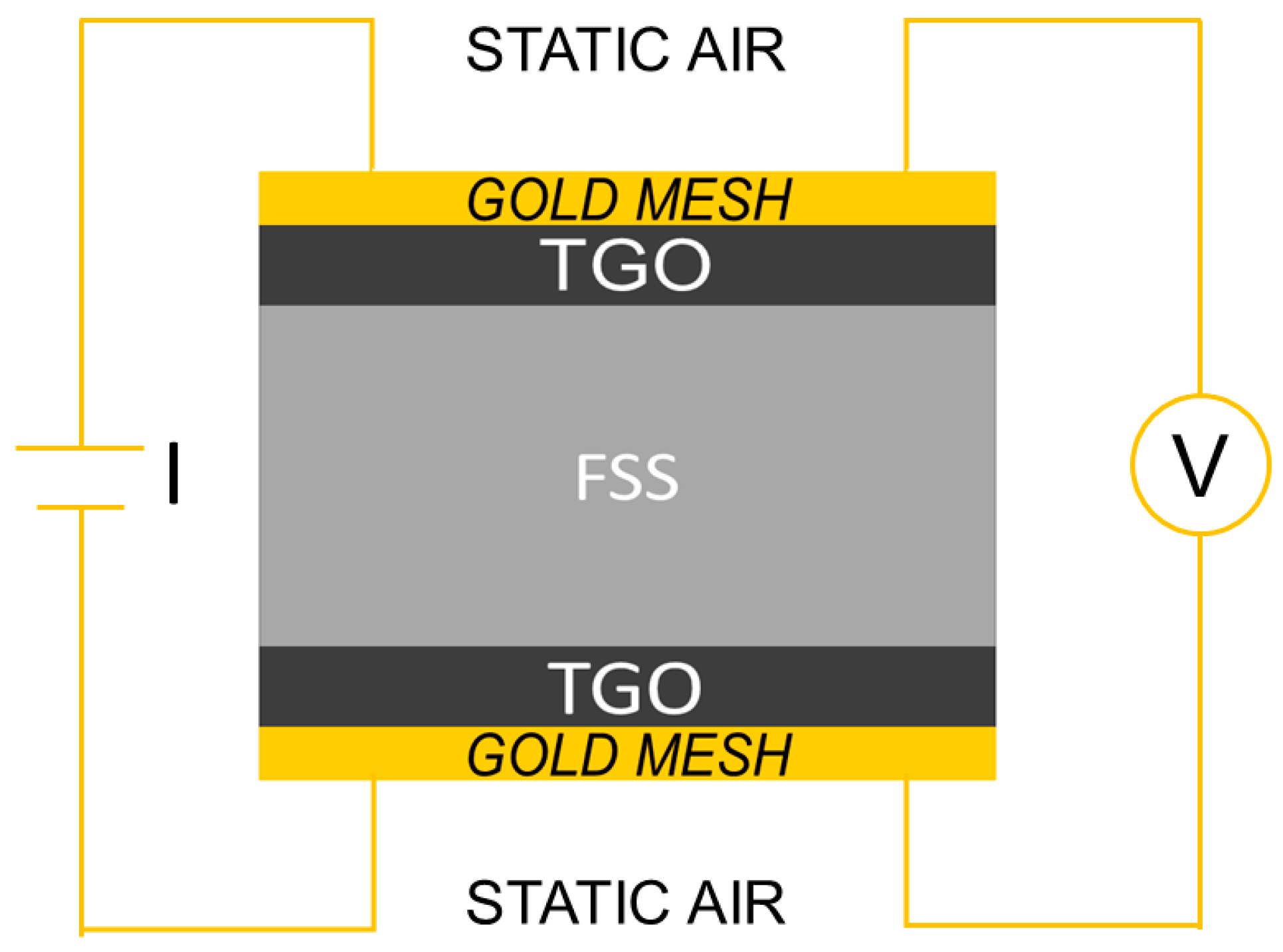
Figure 1. Schematic drawing of Area Specific Resistance (ASR) measurement setup.
Metals 11 00405 g001
Figure 2. Comparison among weight gain data for Steel A and Steel B (experimental), and AISI 441, AISI 430, and Crofer 22H reprinted with permission from ref. [45], copyright 2021 Elsevier. All the measurements were carried out during oxidation in air at 750 °C.
Metals 11 00405 g002
Figure 3. Comparison between weight gain and ASR data for Steel A (a) and Steel B (b).
Metals 11 00405 g003
Figure 4. SEM-SE micrographs, Steel A surface (1000×, a) and (10,000×, b).
Metals 11 00405 g004
Figure 5. SEM-SE micrograph, Steel B surface (1000×, a) and (10,000×, b).
Metals 11 00405 g005
Figure 6. Steel A—SEM-SE micrograph (5000×), and location of Energy Dispersive X-ray Fluorescence Spectroscopy (EDS) analyses.
Metals 11 00405 g006
Figure 7. Steel B—SEM-SE micrograph (10,000×), and location of EDS analyses.
Metals 11 00405 g007
Figure 9. SEM-SE micrographs of Steel A (a) and Steel B (b) cross-sections, 20,000×; EDS semi-quantitative distribution profiles of elements of Steel A (c) and Steel B (d) performed along the yellow arrow of (a,b).
Metals 11 00405 g009
Figure 10. Steel A—SEM-SE micrograph of the oxide scale with spots and area of EDS analyses, 20,000× (a) EDS quantitative profile (b) and EDS elemental maps (cg).
Metals 11 00405 g010
Figure 11. Steel B—SEM-SE micrograph of the oxide scale with spots and area of EDS analyses, 20,000× (a) EDS quantitative profile (b), SEM—backscattered electron (BSE) micrograph highlighting Laves phases (c), and EDS elemental maps (dh).
Metals 11 00405 g011aMetals 11 00405 g011b
Table 1. Nominal composition (wt.%) of Steel A and Steel B [36].
SamplesElements
FeCCrCuMoNbTiNOthers
Steel ABal.0.00514.11.2--0.180.010<1
Steel BBal.0.00517.11.20.30.540.110.010<1
Table 2. Comparison among the parabolic oxidation rate constant (Kp) of Steel A, Steel B, and those found in literature for Crofer 22H, 441, and 430 FSSs [45]. All were derived from weight gain measurements during oxidation in air at 750 °C.
SteelsKp [g2cm−4s−1]
Steel A9.0 × 10−15
Steel B8.4 × 10−15
Crofer 22H3.2 × 10−15
4411.1 × 10−14
4304.7 × 10−15
Table 3. Results of EDS analyses (at.%) performed at points of Figure 6.
PointElements
OAlSiCrMnFeCu
1461-1320173
252--1021143
354-115228-
Table 4. Results of EDS analyses (at.%) performed at points of Figure 7.
PointElements
OAlSiTiCrMnFeCu
159--121163-
2551--162053
362-112655-
46011126281
5544--212161
Table 5. Results of Micro-Raman Spectroscopy (μ–RS) and XRD analyses performed on the surfaces and cross-sections of Steel A and Steel B.
STEELMain Compounds
μ-RSXRD
ACr2O3
MnxCr3−xO4
Substrate (Fe,Cr) alloy
Cr2O3
TiO2
Mn1.5Cr1.5O4
B
Table 6. Results of EDS analysis performed at spots of Figure 10a.
SpectrumElements (wt.%)
CrMnCu
123212
232292
332212
43481
5357<0.5
61511
713<0.51
813<0.51
913<0.5<0.5
Table 7. Results of EDS analysis performed at spots of Figure 11a.
SpectrumElements (wt.%)
CrMnCu
153275
244178
34894
43531
51911
616<0.51
716<0.51
816<0.51
916<0.5<0.5
1017<0.51
Publisher’s Note: MDPI stays neutral with regard to jurisdictional claims in published maps and institutional affiliations.