
Environmental Effect on Fatigue Crack Initiation under Equi-Biaxial Loading of an Austenitic Stainless Steel

 and
and 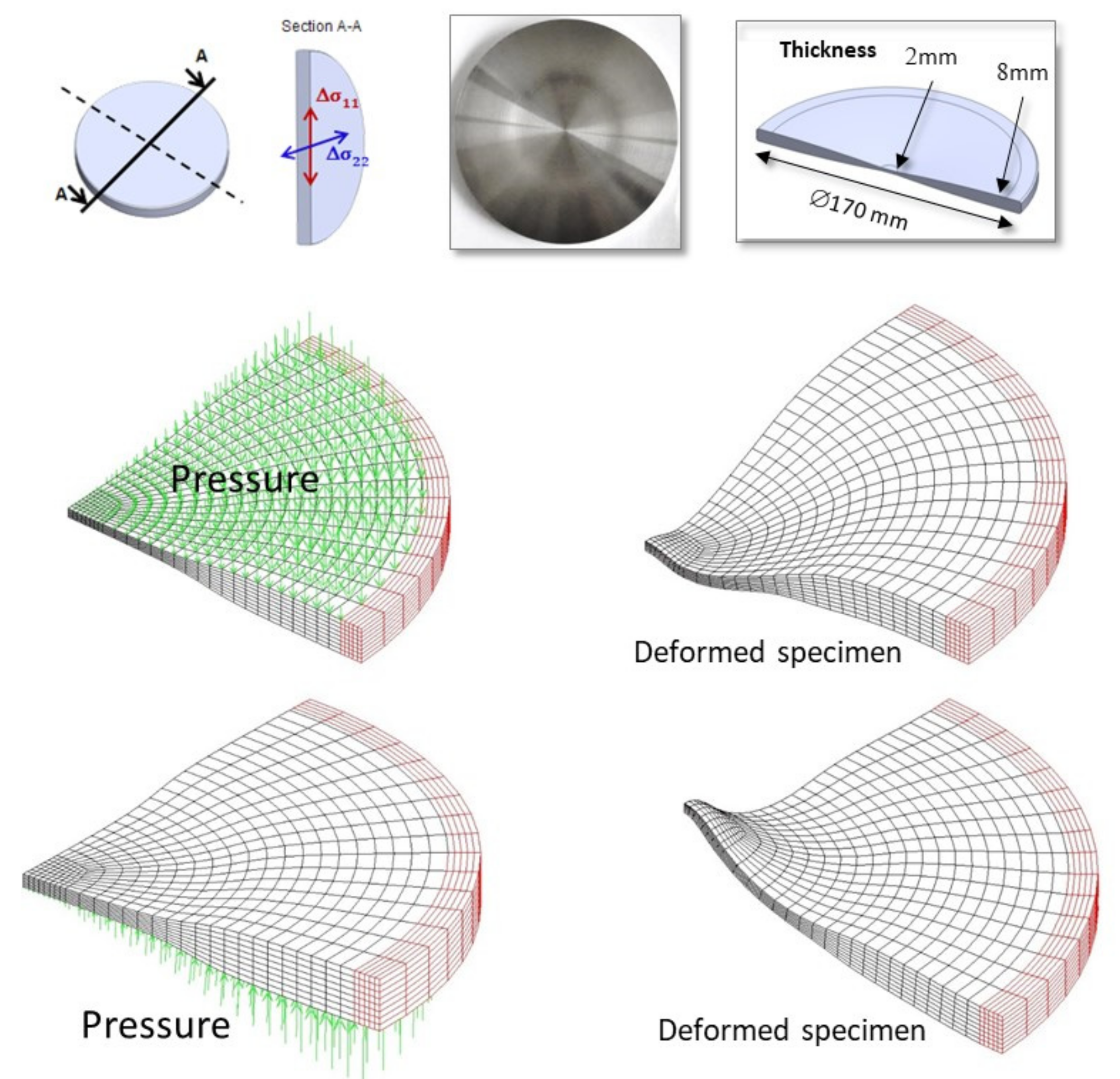
Abstract
1. Introduction
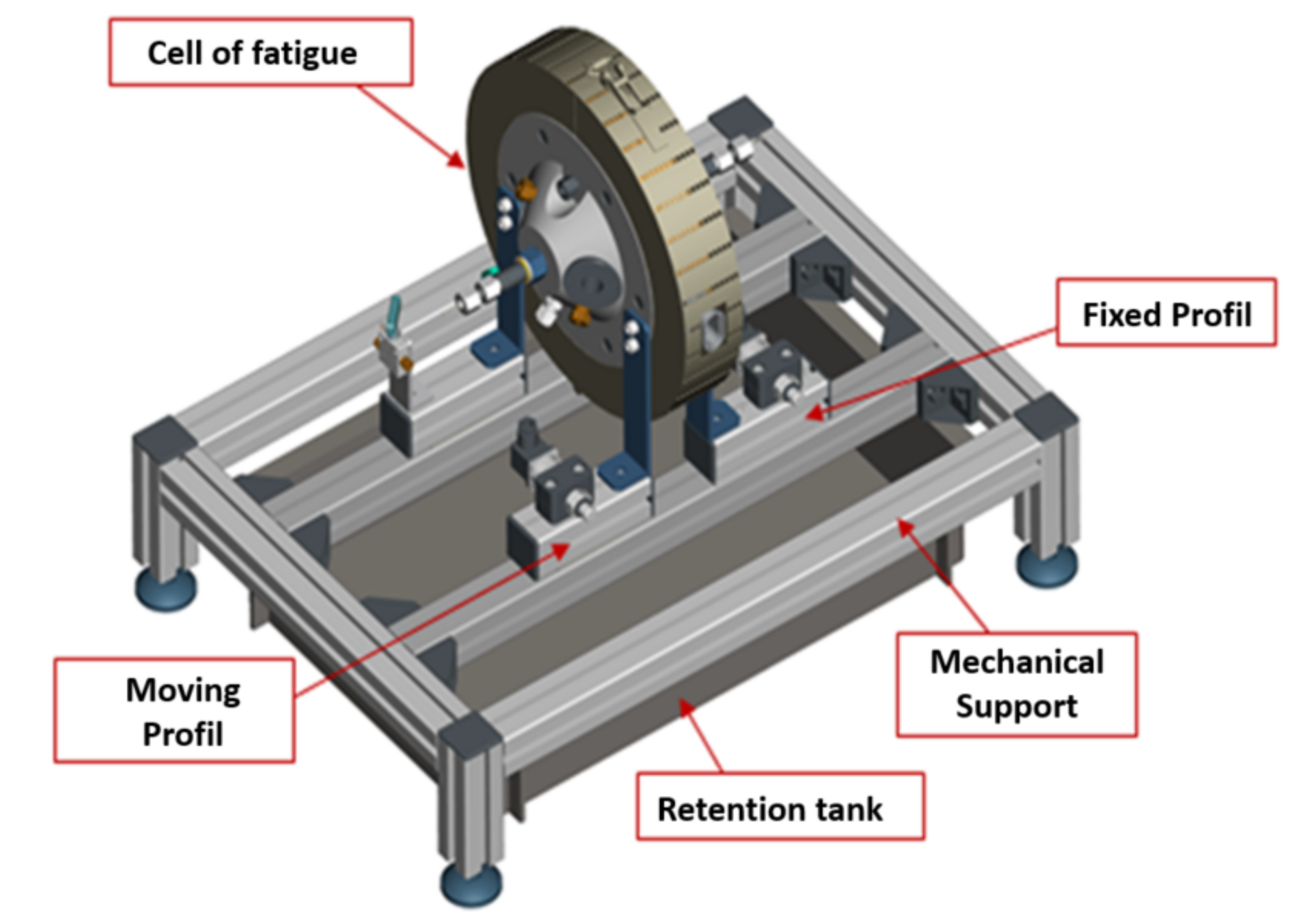
2. The Equibiaxial Fatigue Device with Oil Environment
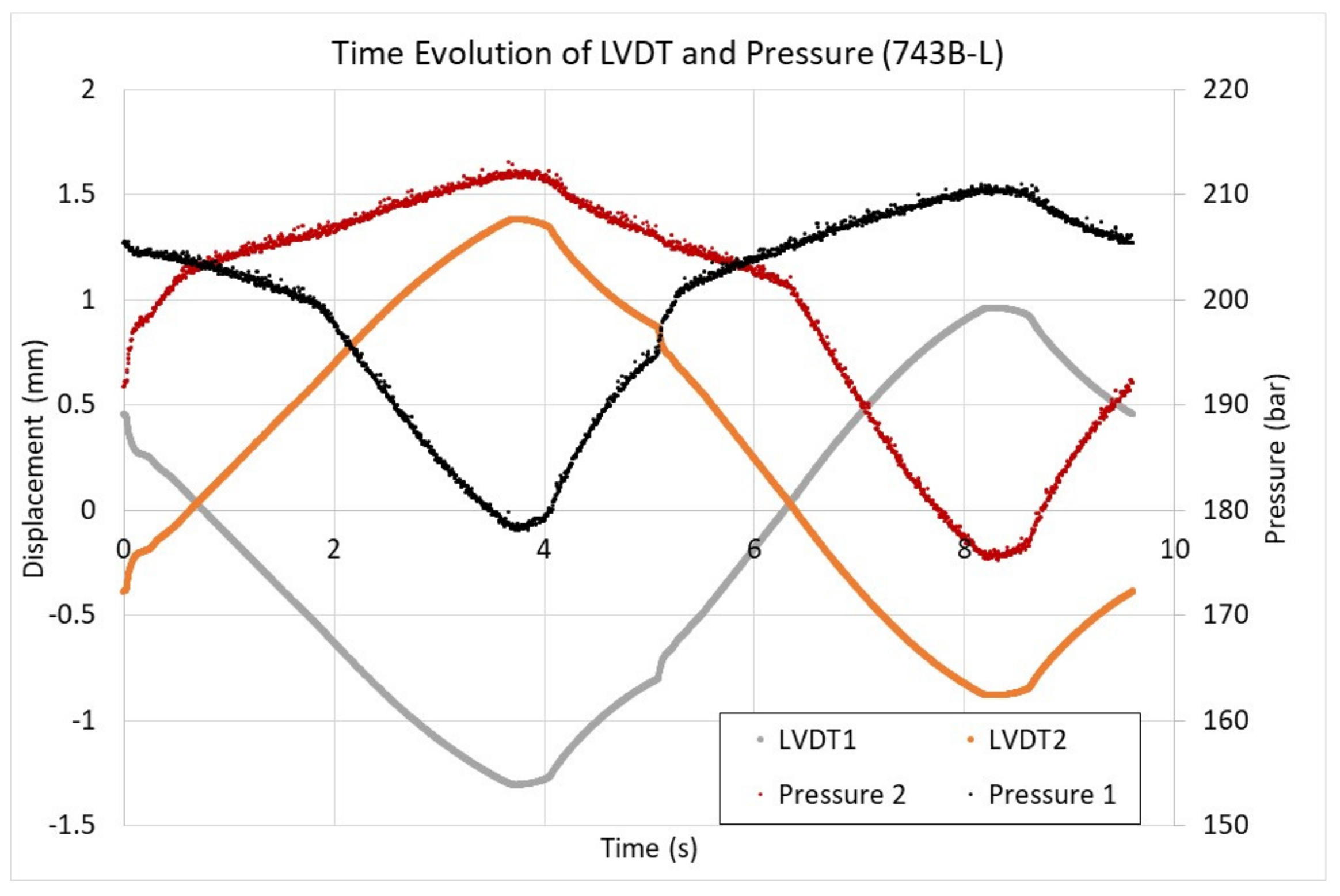
- Either in imposed displacement: by measuring the deflection in the center of the specimen via LVDTs (linear variable differential transformers) positioned in the center of the specimen; or
- In imposed pressure: by a measurement of the pressure level in the chamber of the fatigue cell.
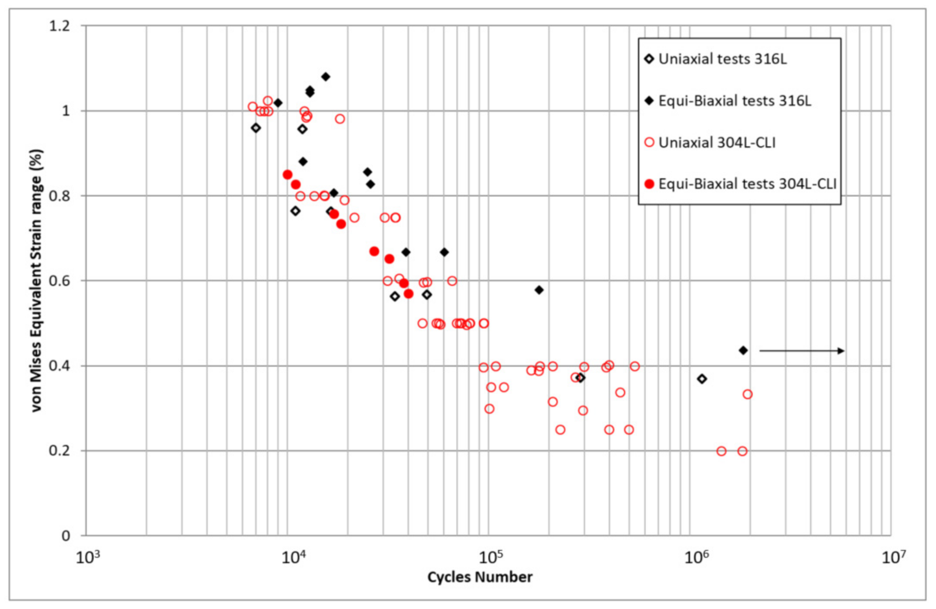
3. The Experimental Results from FABIME2 and Interpretation
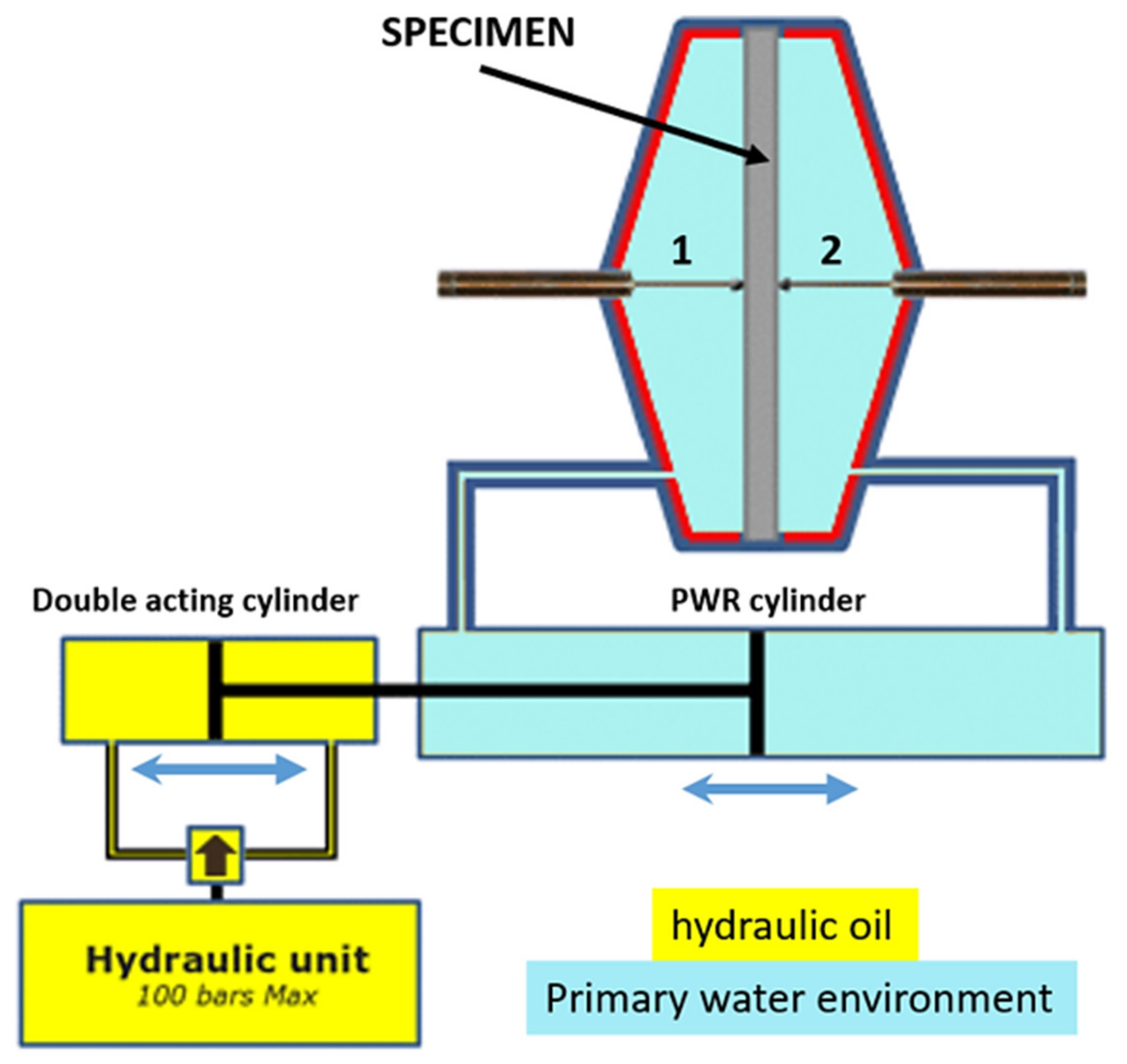
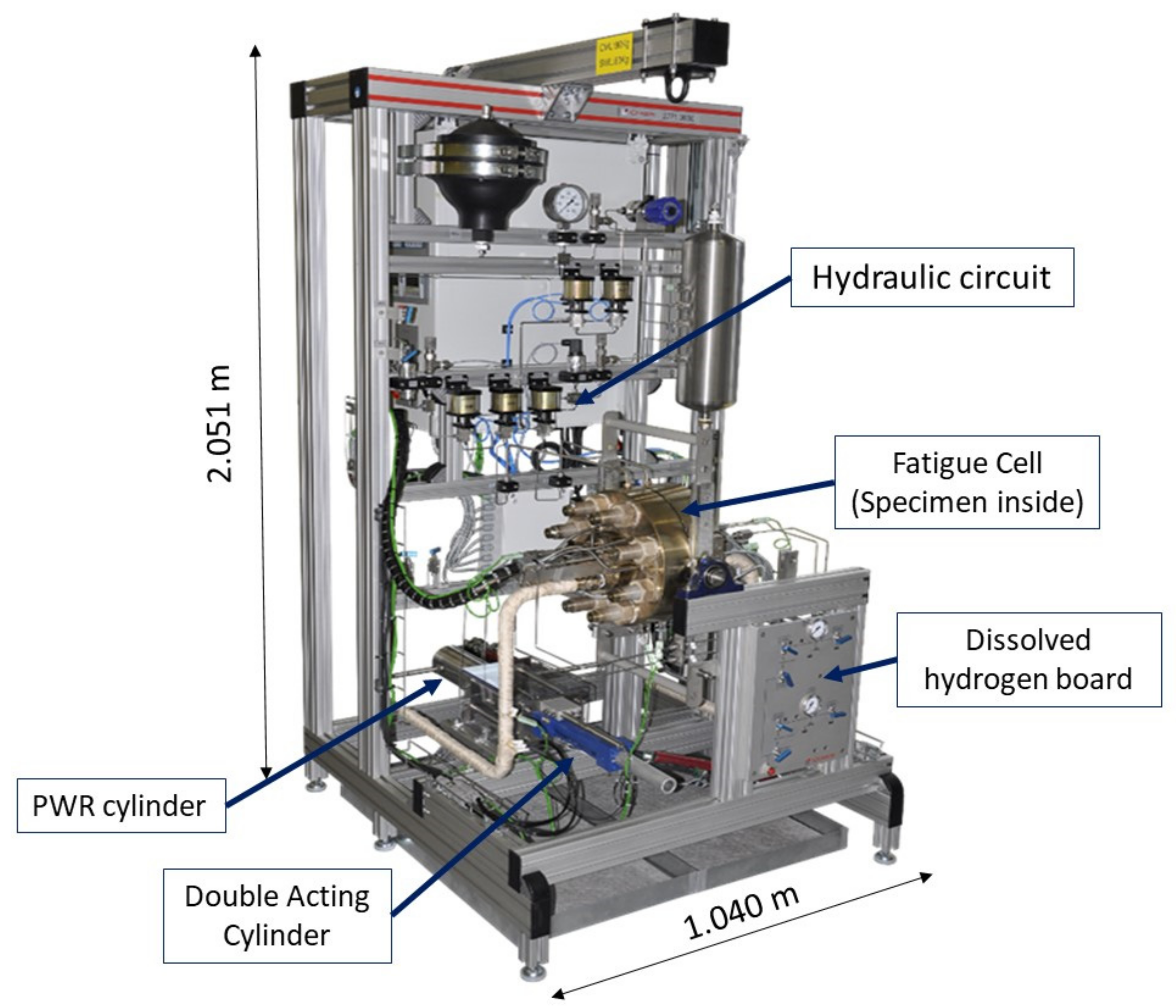
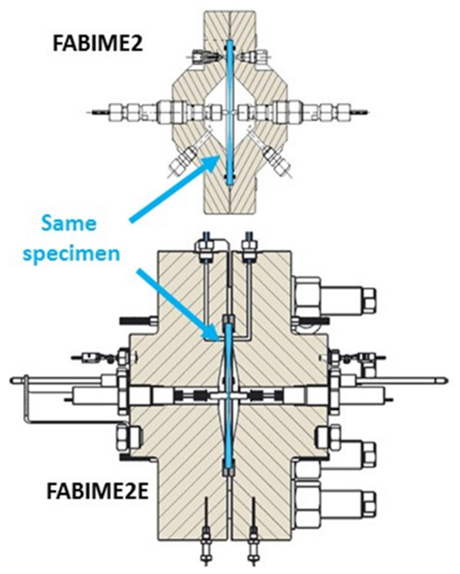
4. The Equibiaxial Fatigue Device with PWR Conditions: FABIME2e
4.1. Presentation of the Equibiaxial Fatigue Device with PWR Conditions: FABIME2e
- A higher operating temperature, of the order of 340 °C;
- A higher pressure to ensure that the environment remains monophasic, of the order of 150 bars;
- A control of the chemistry of the environment and in particular the level of dissolved hydrogen;
- The specimen is in permanent contact with the PWR environment.
4.2. Description of the Equibiaxial Fatigue Device: FABIME2e
- Type K thermocouples allowing the temperature of the environment as well as the temperature gradient within it to be measured;
- Pressure sensors with a capacity of 400 bars;
- LVDT-type specimen center displacement sensors from RDPE Industry (these displacement sensors support PWR environment conditions and their measuring range is ±5 mm);
- Two Pd–Ag hydrogen sensors from Framatome: one for measuring and one for adjusting the dissolved hydrogen level if necessary.
5. First Equibiaxial Fatigue Tests under Distilled Water Conditions
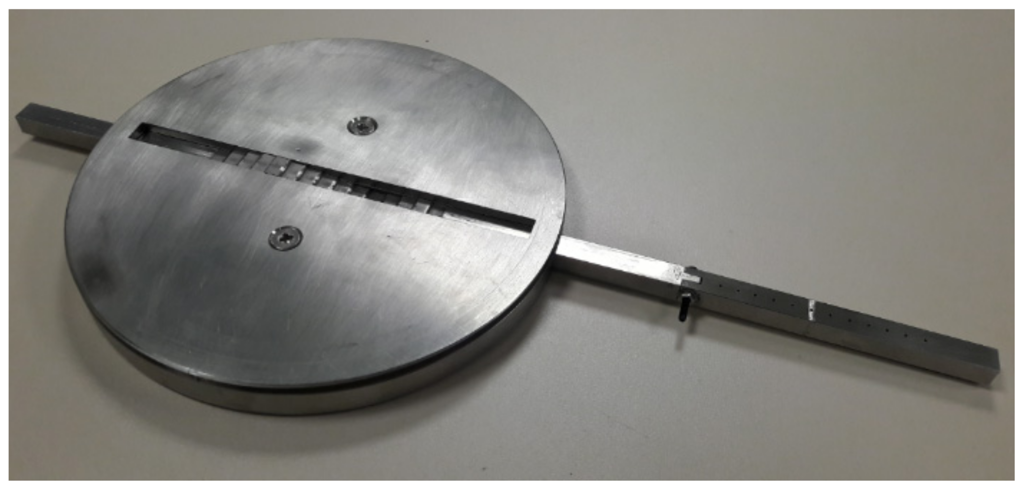
5.1. Deflection Calibration
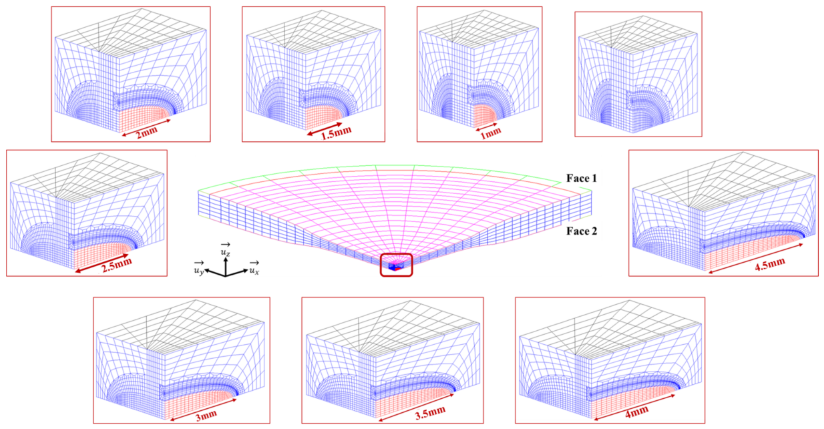
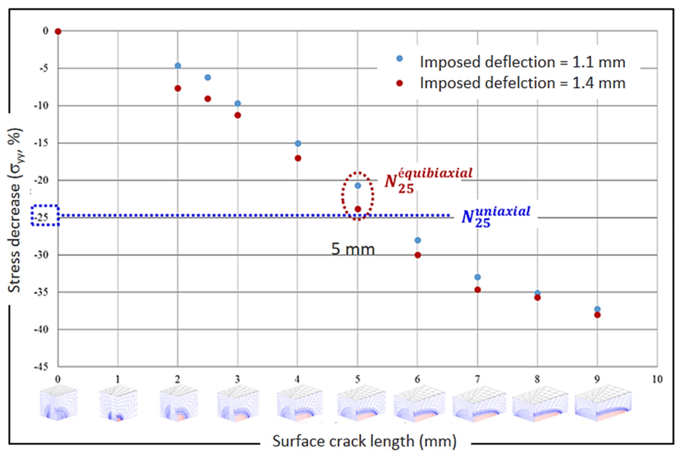
5.2. Discussion of the Crack Initiation Criteria
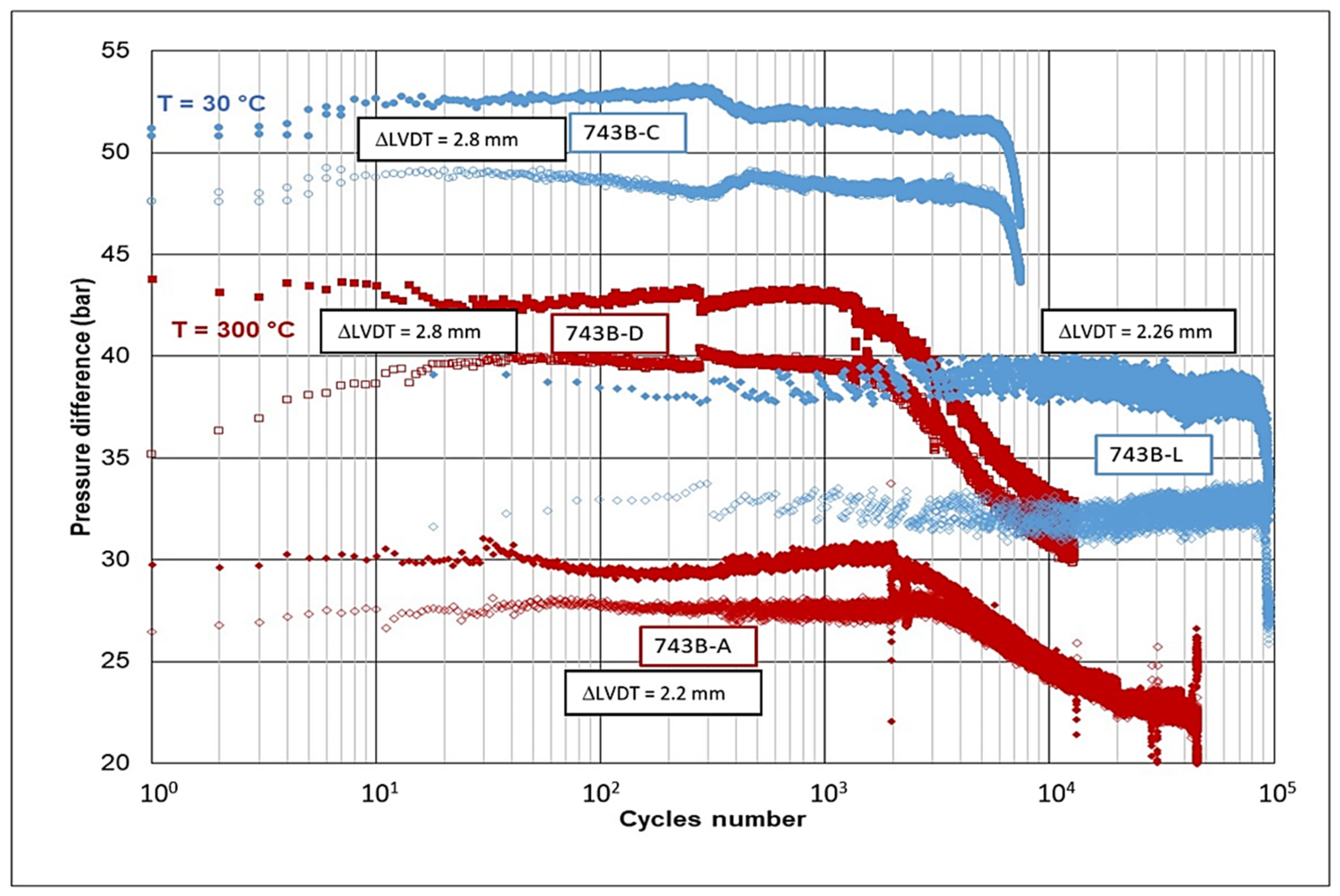
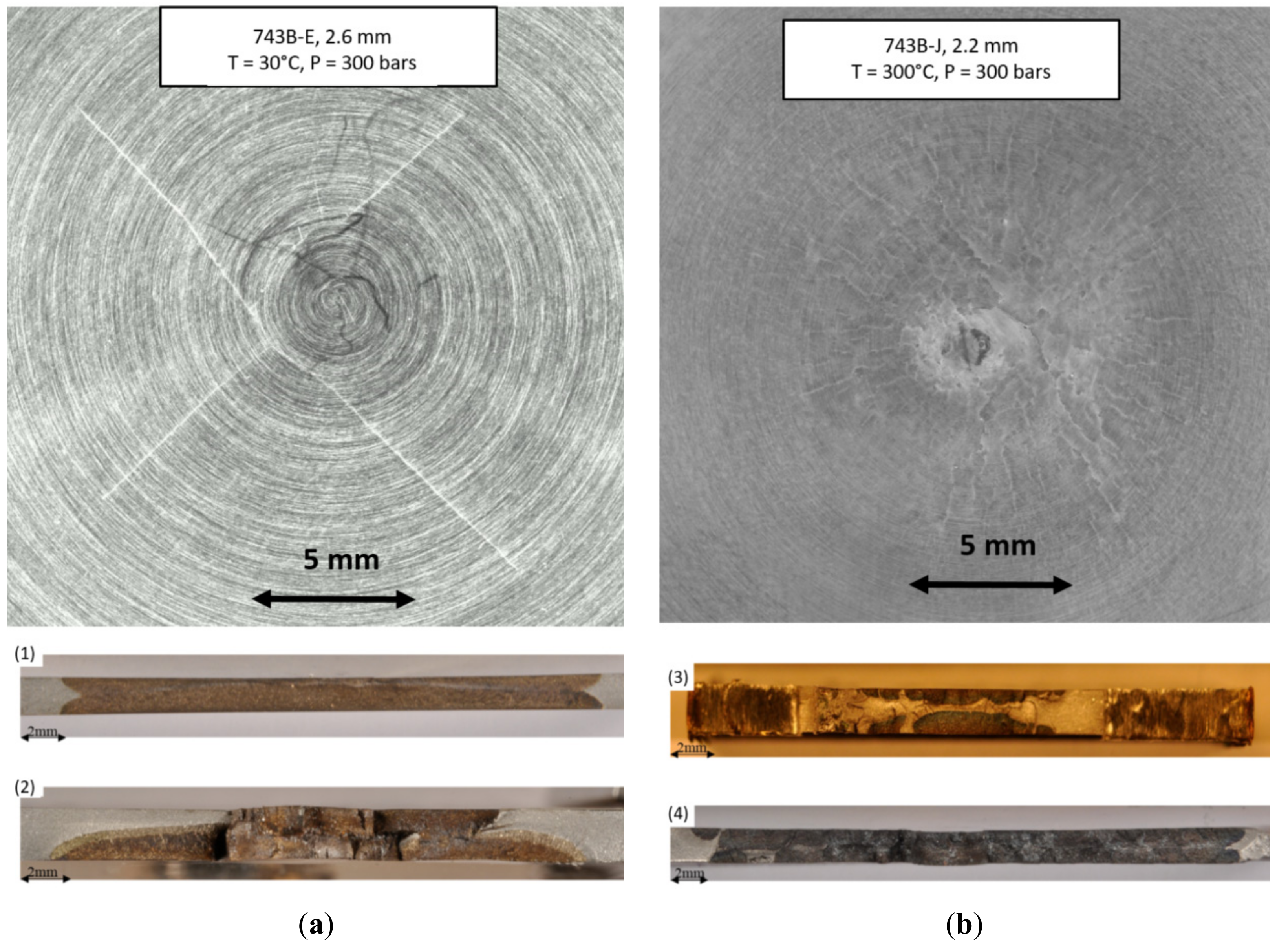
5.3. Experimental Results of Distilled Water Conditions
6. Conclusions
Author Contributions
Funding
Institutional Review Board Statement
Informed Consent Statement
Data Availability Statement
Acknowledgments
Conflicts of Interest
References
- Chopra, O.K.; Shack, W.J. Effect of LWR Coolant Environments on the Fatigue Life of Reactor Materials; Office of Nuclear Regulatory Research: Washington DC, USA, 2017.
- AFCEN. RCC-M (2007)—Design and Construction Rules for Mechanical Components of Nuclear PWR Plants—2007 Edition with Addenda in 2008, 2009 and 2010; AFCEN: Courbevoie, France, 2010; Available online: http://www.afcen.com/en/ (accessed on 15 September 2020).
- AFCEN. RSE-M In-Service Inspection Rules for Mechanical Components of PWR Nuclear Islands; AFCEN: Courbevoie, France, 2010; Available online: http://www.afcen.com/en/ (accessed on 15 September 2020).
- AFCEN. Unfired Pressure Vessels—Part 3: Design; AFCEN: Courbevoie, France, 2014; Available online: http://www.afcen.com/en/ (accessed on 15 September 2020).
- AFCEN. RCC-MRx 2012: Règles de Conception et de Construction des Matériels Mécaniques des Installations Nucléaires Applicables aux Structures À Haute Température et à L’enceinte à Vide ITER; AFCEN: Courbevoie, France, 2012; Available online: http://www.afcen.cop/en/ (accessed on 15 September 2020).
- Fissolo, A.; Amiable, S.; Ancelet, O.; Mermaz, F.; Stelmaszyk, J.; Constantinescu, A.; Robertson, C.; Vincent, L.; Maillot, V.; Bouchet, F. Crack initiation under thermal fatigue: An overview of CEA experience. Part I: Thermal fatigue appears to be more damaging than uniaxial isothermal fatigue. Int. J. Fatigue 2009, 31, 587–600. [Google Scholar] [CrossRef]
- Lefebvre, D.F. Hydrostatic pressure effect on life prediction in biaxial low-cycle fatigue. In Biaxial and Multiaxial Fatigue (EGF 3); Mechanical Engineering Publications: London, UK, 1989; pp. 511–533. [Google Scholar]
- Itoh, T.; Sakane, M.; Hata, T.; Hamada, N. A design procedure for assessing low cycle fatigue life under proportional and non-proportional loading. Int. J. Fatigue 2006, 28, 459–466. [Google Scholar] [CrossRef]
- Parsons, M.W.; Pascoe, K.J. Development of a biaxial fatigue testing rig. J. Strain Anal. 1975, 10, 1–9. [Google Scholar] [CrossRef]
- Shimada, H.; Shimizu, K.; Obata, M.; Chikugo, K.; Chiba, M. A New Biaxiai Testing Machine for the Flat Specimen and a Fundamental Study on the Shape of the Specimen; Technology Reports; Tohoku University: Sendai, Japan, 1976; pp. 351–369. [Google Scholar]
- Ives, K.D.; Kooistra, L.F.; Tucker, J.T. Equibiaxial low-cycle fatigue properties of typical pressure-vessel steels. J. Basic Eng. 1966, 88, 745–754. [Google Scholar] [CrossRef]
- Shewchuk, J.; Zamrik, S.Y.; Marin, J. Low-cycle fatigue of 7075-T651 aluminum alloy in biaxial bending. Exp. Mech. 1968, 8, 504–512. [Google Scholar] [CrossRef]
- Kamaya, M. Development of disc bending fatigue test technique for equi-biaxial loading. Int. J. Fatigue 2016, 82, 561–571. [Google Scholar] [CrossRef]
- Poncelet, M.; Barbier, G.; Raka, B.; Courtin, S.; Desmorat, R.; Le-Roux, J.C.; Vincent, L. Biaxial high cycle fatigue of a type 304L stainless steel: Cyclic strains and crack initiation detection by digital image correlation. Eur. J. Mech. A Solids 2010, 29, 810–825. [Google Scholar] [CrossRef][Green Version]
- Bradai, S.; Gourdin, C.; Courtin, S.; Leroux, J.C.; Gardin, C. Crack initiation under equibiaxial fatigue, development of a particular equibiaxial fatigue device. In Proceedings of the ASME 2013 Pressure Vessels and Piping Conference, Paris, France, 14–18 July 2013. [Google Scholar]
- De Baglion, L.; Mendez, J.; Le Duff, J.-A.; Lefrancois, A. Influence of PWR primary water on LCF behavior of type 304L austenitic stainless steel at 300 °C—Comparison with results obtained in vacuum or in air. In Proceedings of the ASME 2012 Pressure Vessels and Piping Conference, Toronto, ON, Canada, 15–19 July 2012. [Google Scholar]
- Smith, J.L.; Choppra, O.K. Crack Initiation in Smooth Fatigue Specimens of Austenitic Stainless Steels in Light Water Reactor Environments; Argonne National Laboratory: Lemont, IL, USA, 1999; Volume 395, pp. 235–242. [Google Scholar]
- Bradaï, S.; Gourdin, C.; Gardin, C. Study of crack propagation under fatigue equibiaxial loading. In Proceedings of the ASME 2014 Pressure Vessels and Piping Conference, Anaheim, CA, USA, 20–24 July 2014. [Google Scholar]
- Bradaï, S.; Gourdin, C.; Courtin, S.; Le Roux, J.C.; Gardin, C. Equi-biaxial loading effect on austenitic stainless steel fatigue life. In Proceedings of the ASME 2015 Pressure Vessels and Piping Conference, Boston, MA, USA, 19–23 July 2015. [Google Scholar]


Publisher’s Note: MDPI stays neutral with regard to jurisdictional claims in published maps and institutional affiliations. |
© 2021 by the authors. Licensee MDPI, Basel, Switzerland. This article is an open access article distributed under the terms and conditions of the Creative Commons Attribution (CC BY) license (http://creativecommons.org/licenses/by/4.0/).
Share and Cite
Gourdin, C.; Perez, G.; Dhahri, H.; De Baglion, L.; Le Roux, J.-C. Environmental Effect on Fatigue Crack Initiation under Equi-Biaxial Loading of an Austenitic Stainless Steel. Metals 2021, 11, 203. https://doi.org/10.3390/met11020203
Gourdin C, Perez G, Dhahri H, De Baglion L, Le Roux J-C. Environmental Effect on Fatigue Crack Initiation under Equi-Biaxial Loading of an Austenitic Stainless Steel. Metals. 2021; 11(2):203. https://doi.org/10.3390/met11020203
Chicago/Turabian StyleGourdin, Cédric, Grégory Perez, Hager Dhahri, Laurent De Baglion, and Jean-Christophe Le Roux. 2021. "Environmental Effect on Fatigue Crack Initiation under Equi-Biaxial Loading of an Austenitic Stainless Steel" Metals 11, no. 2: 203. https://doi.org/10.3390/met11020203
APA StyleGourdin, C., Perez, G., Dhahri, H., De Baglion, L., & Le Roux, J.-C. (2021). Environmental Effect on Fatigue Crack Initiation under Equi-Biaxial Loading of an Austenitic Stainless Steel. Metals, 11(2), 203. https://doi.org/10.3390/met11020203