
A New Approach to Low-Cost, Solar Salt-Resistant Structural Materials for Concentrating Solar Power (CSP) and Thermal Energy Storage (TES)


Abstract
:1. Introduction
2. Materials and Methods
2.1. Materials and Preparation
2.1.1. Structural Materials
Crofer®22 H
LB2230
Haynes 214
2.1.2. Solar Salt
2.2. Experimental Methods
2.2.1. Corrosion Testing
2.2.2. Chemical Salt Analysis
2.2.3. Metallographic Preparation and Microstructural Investigation
3. Results and Discussion
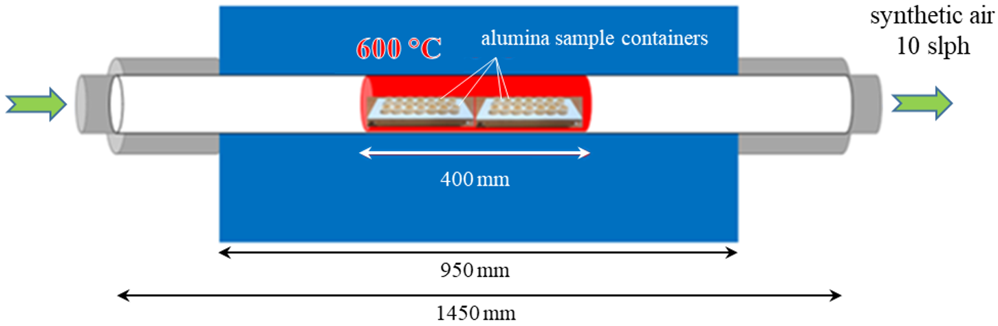
3.1. Pre-Oxidation
3.2. Weight Change
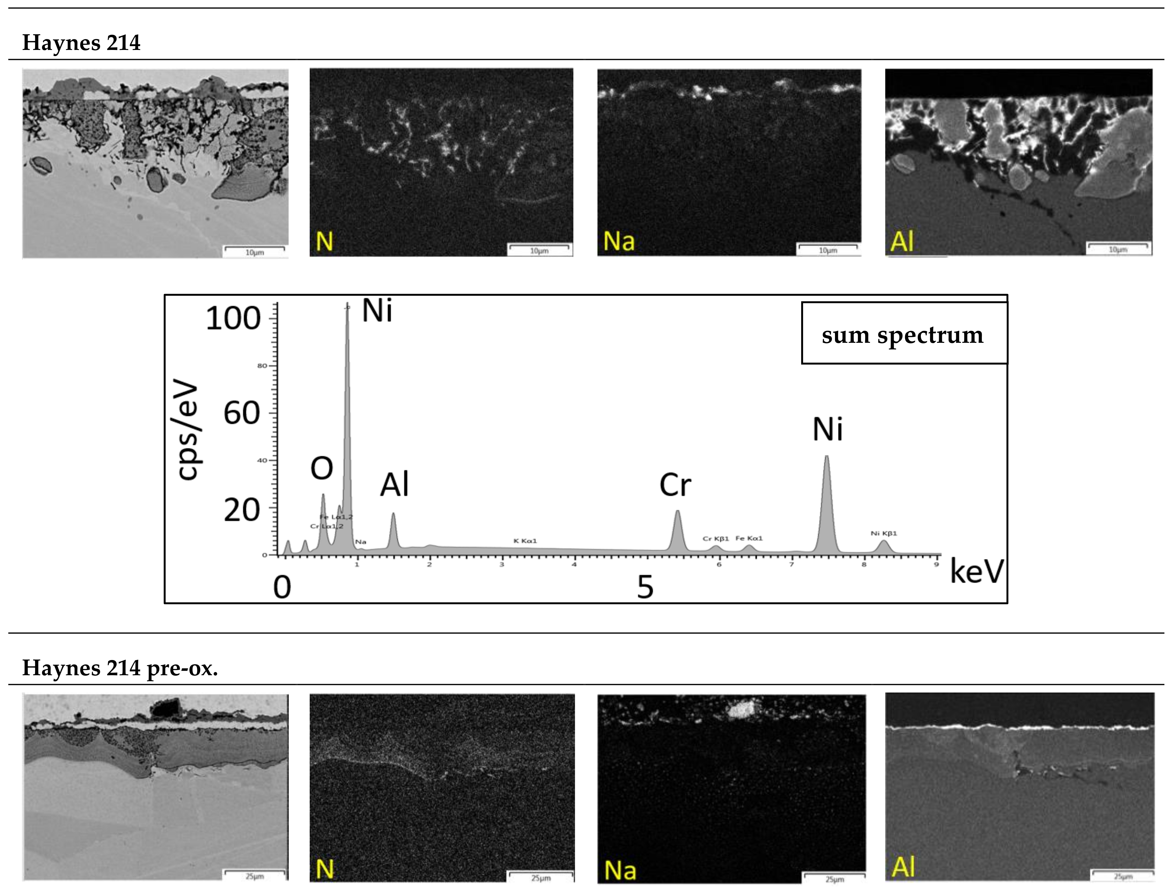
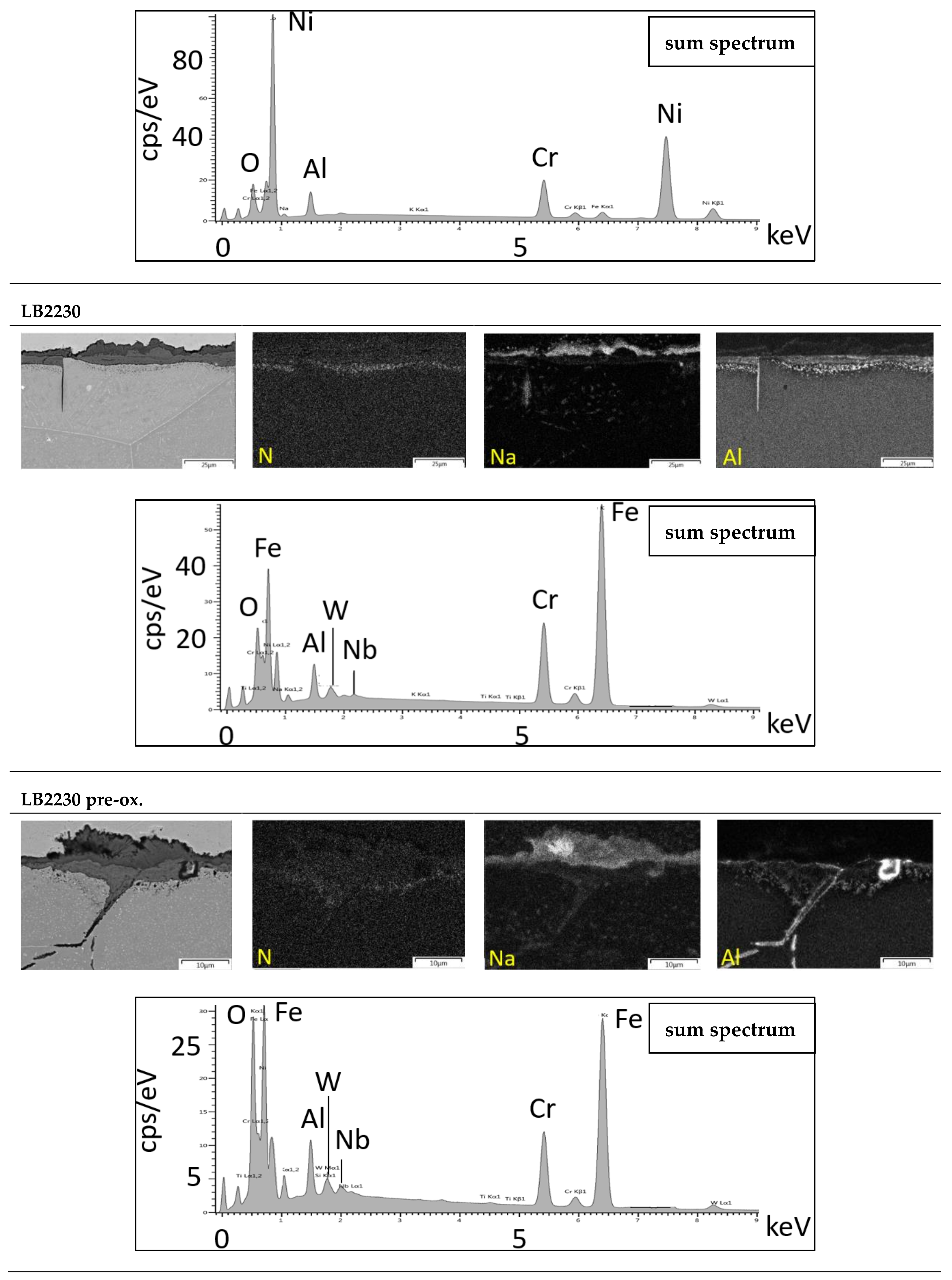
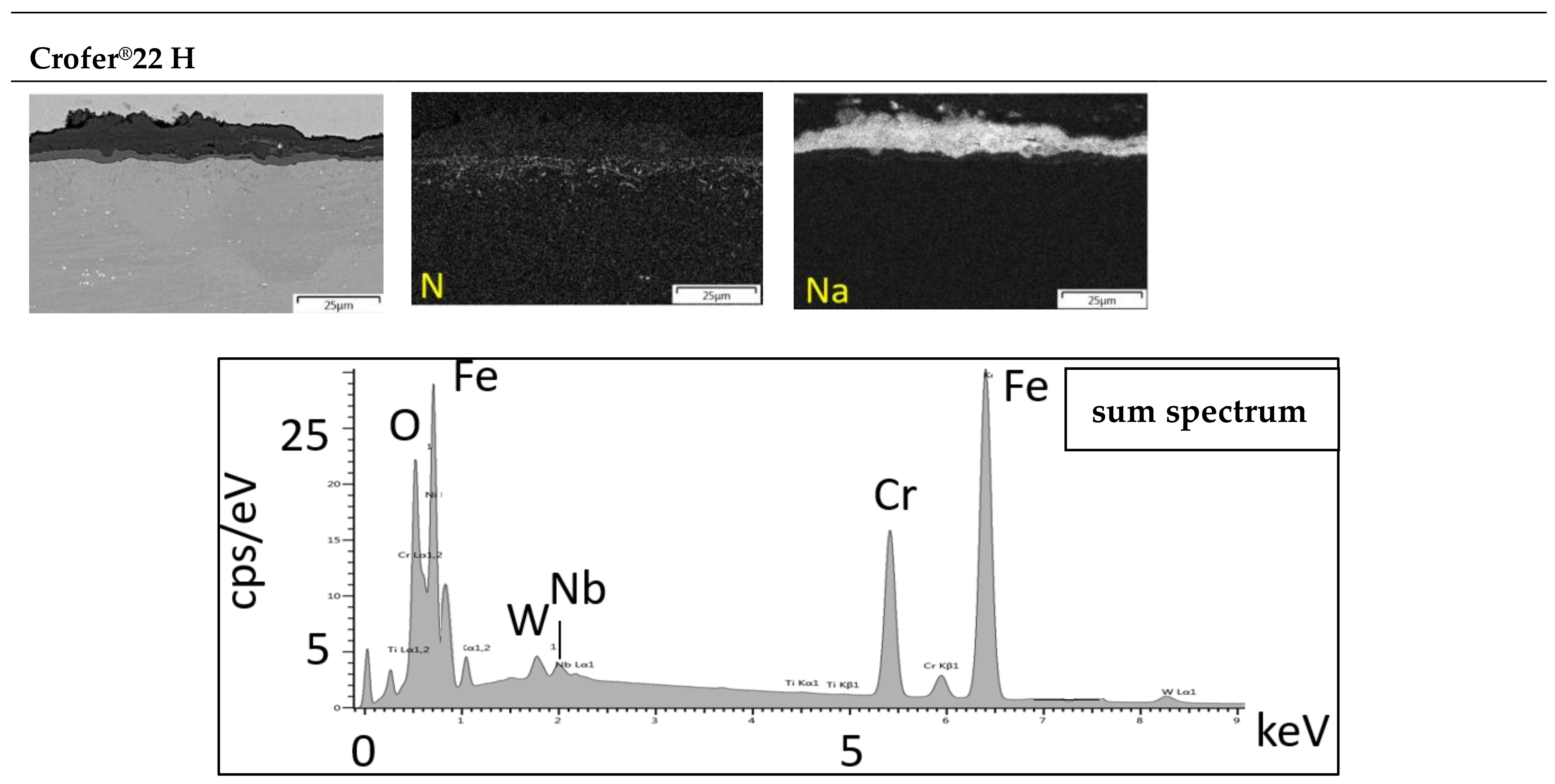
3.3. Microstructure
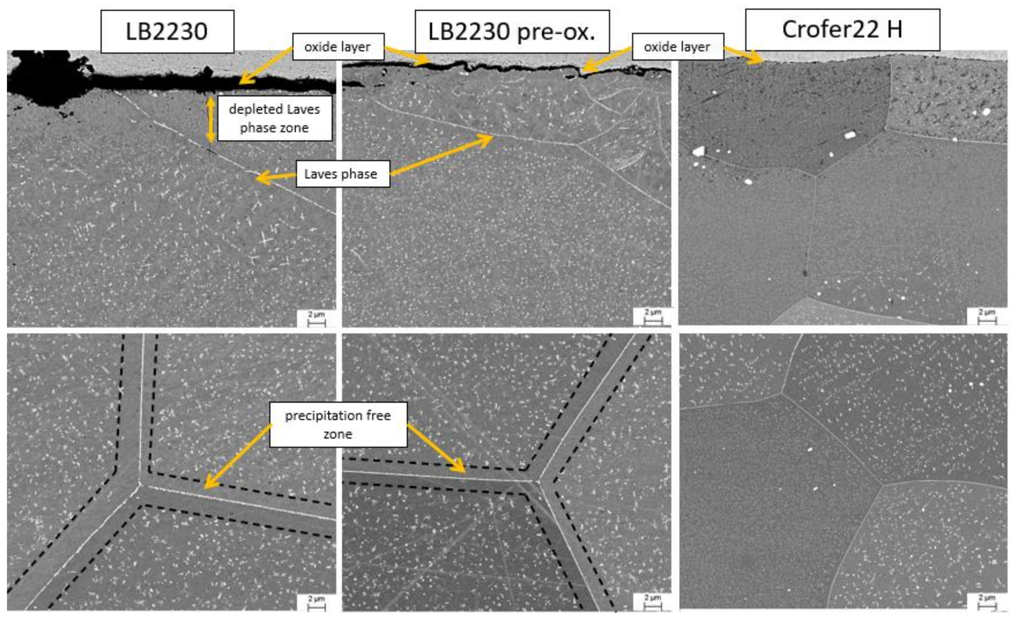
Laves Phase Precipitation
3.4. Salt Analysis
3.4.1. Nitrate Dissociation
3.4.2. Metal Dissolution
4. Conclusions
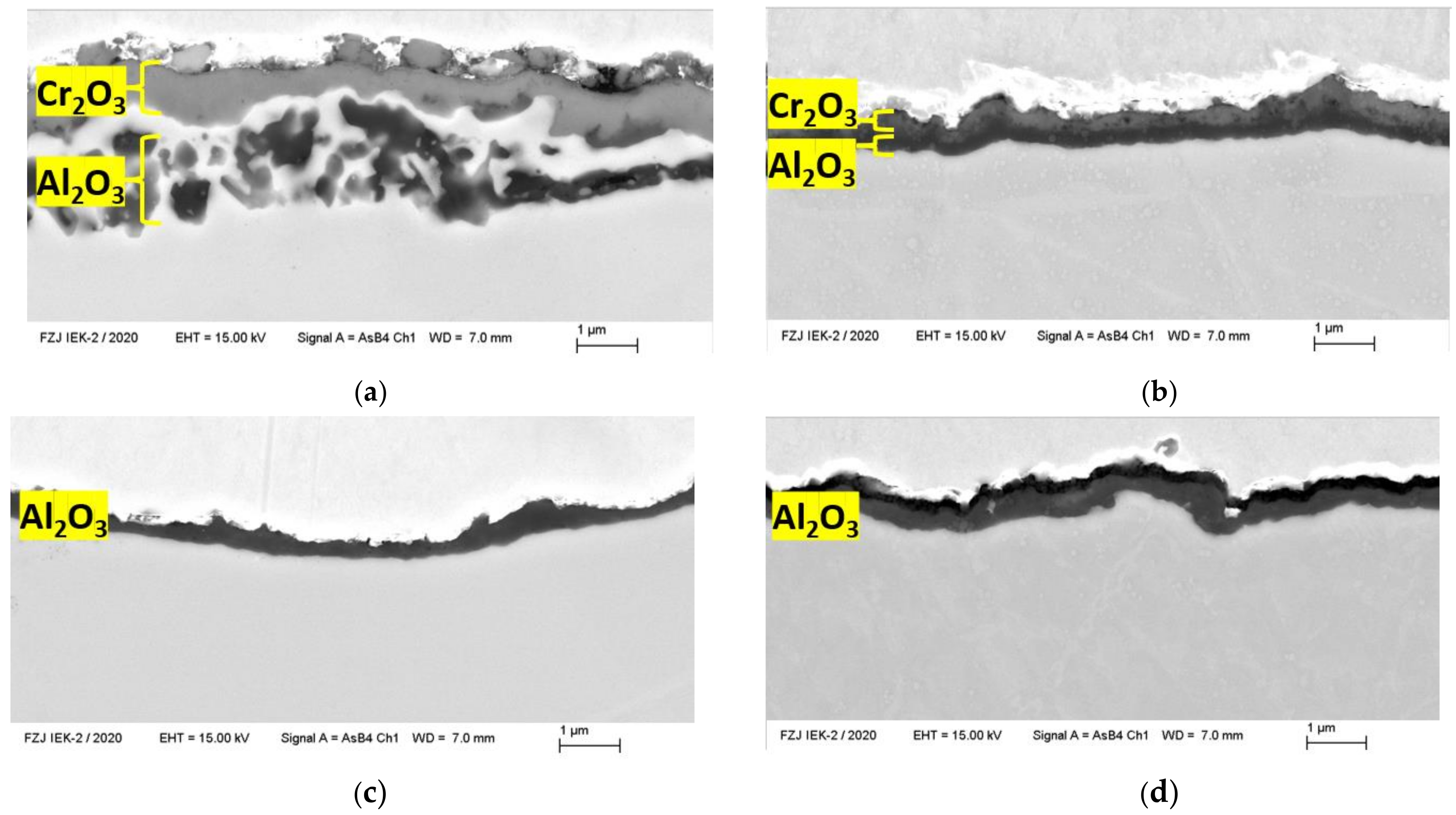
- In air, temperatures typically higher than 1000 °C are needed to grow protective Al2O3 scales on the Al-alloyed trial steel LB2230 and the Ni-base alloy Haynes 214.
- Protective Al mixed oxide scales are obtainable at 600 °C in molten 60 wt.% NaNO3–40 wt.% KNO3 solar salt on these materials.
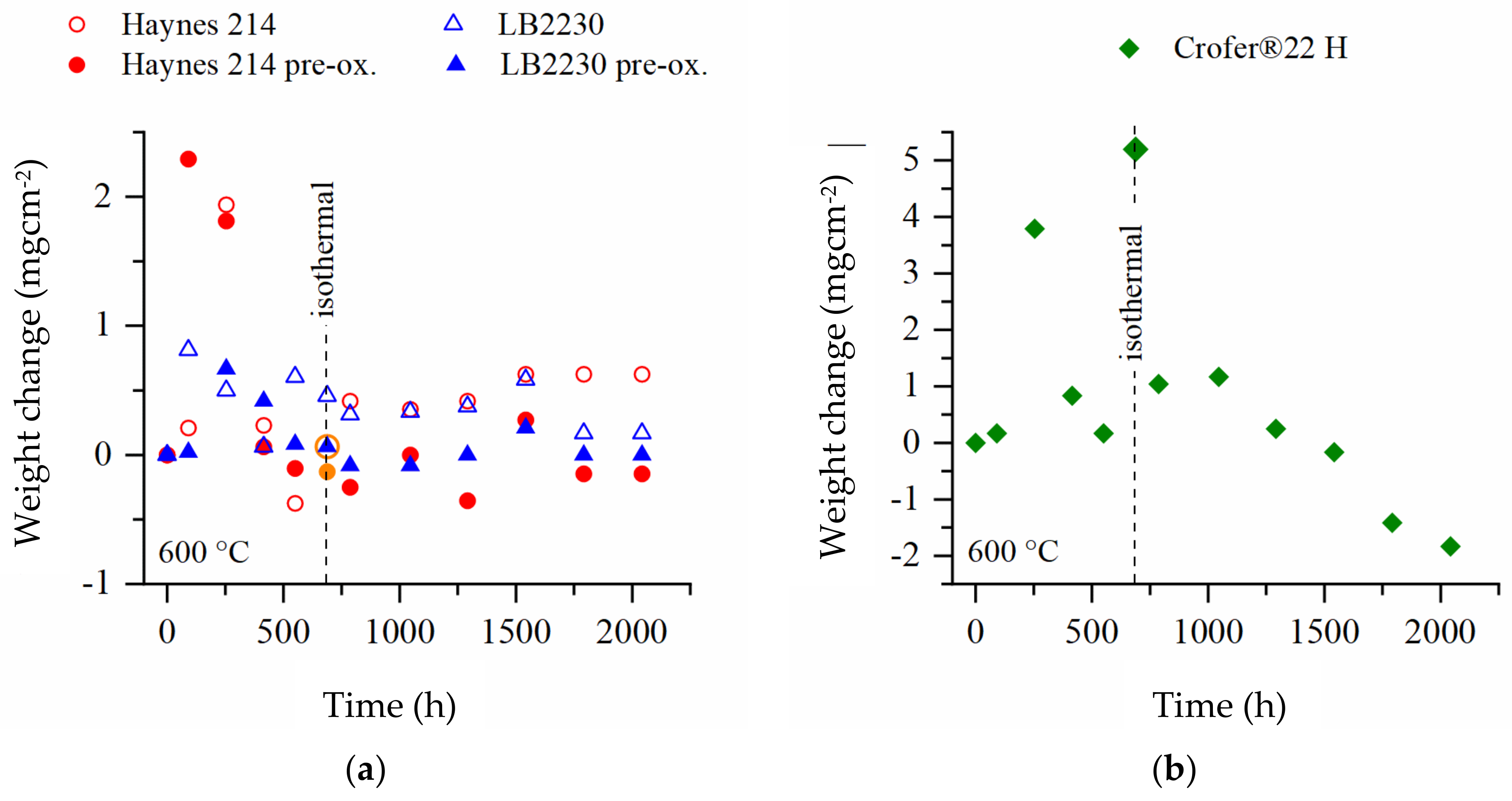
- The Al-alloyed Ni-base superalloy Haynes 214, which was originally developed for application in molten salt environment, demonstrated good performance over a testing period of 2000 h.
- Uniform internal oxidation of Haynes 214 reached a depth of approximately 15 μm.
- The ferritic, stainless, Al-alloyed, Laves phase-strengthened trial steel LB2230 demonstrated weight gains on the niveau of Haynes 214 in discontinous and isothermal salt corrosion experiments.
- Sporadic internal oxidation of LB2230 was limited to a depth of approximately 5 μm.
- LB2230 released a minimum of Cr species into the molten salt.
- With the exception of minimized initial Cr-release in case of Haynes 214, pre-oxidation of the Al-alloyed materials in air did not yield significantly different results.
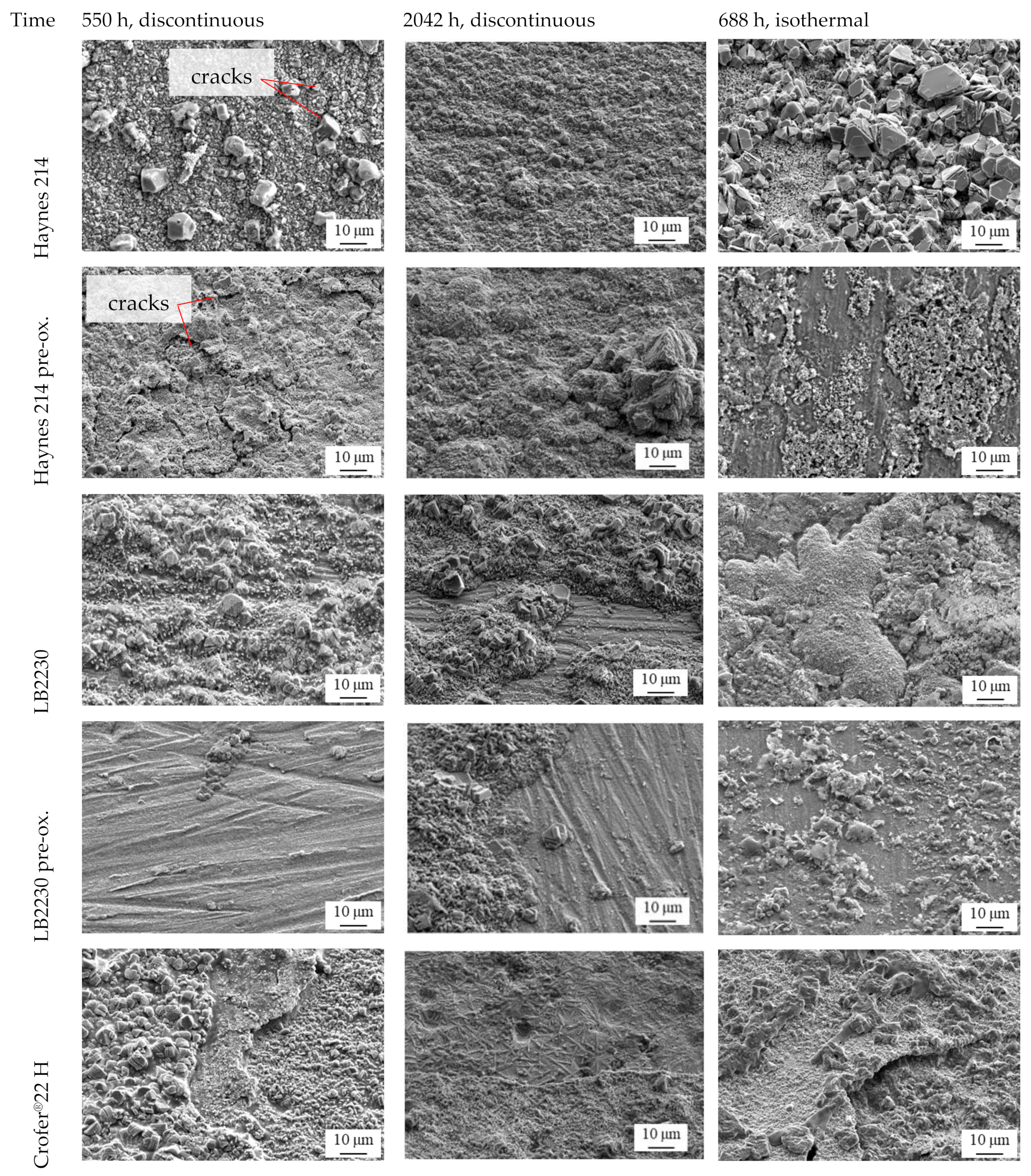
- The ferritic, Cr2O3-forming, Laves phase-strengthened Crofer®22 H steel presented the highest weight changes, did not form stable, protective oxide scales and tended to spallation, especially in discontinous corrosion testing. Therefore, this alloy seems unsuitable for long-term application in molten solar salt.
- In comparison to Haynes 214, decreased internal oxidation, reduced dissolution of Cr species into the molten salt and low material costs make LB2230 a favorable candidate alloy for CSP and TES application.
- NO3 dissociation from solar salt depends on the formation of N-consuming oxide/precipitate phases on/in the immersed metals.
- The strenthening Laves phase precipitates in the ferritic steels were demonstrated to be stable during exposure to molten salt. The strengthening by Laves phase particles in combination with potential self-passivation in case of the Al2O3-forming LB2230 alloy poses immense cost-saving potential over austenitic stainless-steel and especially Ni-base superalloys.
- Increased exposure times to molten salt to safeguard corrosion resistance and microstructural stability.
- In-depth research on corrosion mechanisms and potential competition between oxide scale formation and Laves phase stability in near-surface regions.
- Mechanical property evaluation in molten salt environment.
- Detailed examinatoin of self-healing capacity of cracked oxide scales, especially under thermomechanical fatigue conditions.
Author Contributions
Funding
Institutional Review Board Statement
Informed Consent Statement
Data Availability Statement
Acknowledgments
Conflicts of Interest
References
- Liu, M.; Tay, N.H.S.; Bell, S.; Belusko, M.; Jacob, R.; Will, G.; Saman, W.; Bruno, F. Review on Concentrating Solar Power Plants and New Developments in High Temperature Thermal Energy Storage Technologies. Renew. Sustain. Energy Rev. 2016, 53, 1411–1432. [Google Scholar] [CrossRef]
- Stadler, I.; Kraft, A.; Bauer, T.; Faatz, R.; Grabowski, S.; Harms, G.; Herrmann, U.; Kleimaier, M.; Maximini, M.; Ritterbach, E.; et al. Wärmespeicher in NRW Thermische Speicher in Wärmenetzen Sowie in Gewerbe-Und Industrieanwendungen, Handlungsoptionen Und Ergebnispapier Der Expertengruppe AG3B Wärmespeicher im Netzwerk Netze Und Speicher Der EnergieAgentur. NRW 2020, 36–40. Available online: https://www.energieagentur.nrw/content/anlagen/waermespeicher_in_nrw.pdf (accessed on 16 November 2021).
- Herrmann, U.; Schwarzenbart, M.; Dittmann-Gabriel, S. Speicher Statt Kohle–Integration Thermischer Stromspeicher in Vorhandene Kraftwerksstandorte. BWK 2019, 71, 42–45. [Google Scholar]
- Bauer, T. Energie Aus Dem Salz. BWK 2019, 71, 42–44. [Google Scholar] [CrossRef]
- Steinmann, W.D. Thermo-Mechanical Concepts for Bulk Energy Storage. Renew. Sustain. Energy Rev. 2017, 75, 205–219. [Google Scholar] [CrossRef]
- Herrmann, U.; Schwarzenbart, M.; Sauerborn, M.; Dittmann-Gabriel, S. I-TESS Integration Thermischer Stromspeicher in Existierende Kraftwerksstandorte; SIJ Solar-Institut Jülich: Jülich, Germany, 2017. [Google Scholar]
- Trieb, F.; Thess, A. Storage Plants—A Solution to the Residual Load Challenge of the Power Sector? J. Energy Storage 2020, 31, 101626. [Google Scholar] [CrossRef]
- Vignarooban, K.; Xu, X.; Arvay, A.; Hsu, K.; Kannan, A.M. Heat Transfer Fluids for Concentrating Solar Power Systems—A review. Appl. Energy 2015, 146, 383–396. [Google Scholar] [CrossRef]
- Bauer, T.; Odenthal, C.; Bonk, A. Molten Salt Storage for Power Generation. Chem. Ing. Tech. 2021, 93, 534–546. [Google Scholar] [CrossRef]
- Dunn, R.I.; Hearps, P.J.; Wright, M.N. Molten-Salt Power Towers: Newly Commercial Concentrating Solar Storage. Proc. IEEE 2012, 100, 504–515. [Google Scholar] [CrossRef]
- Bonk, A.; Martin, C.; Braun, M.; Bauer, T. Material investigations on the thermal stability of solar salt and potential filler materials for molten salt storage. AIP Conf. Proc. 2017, 1850, 080008. [Google Scholar]
- Mallco Carpio, A.; Fernandez, A.G.; Preußner, J.; Portillo, C. Corrosion and Mechanical Assessment in LiNO3 Molten Salt as Thermal Energy Storage Material in CSP Plants. In Proceedings of the ISES Solar World Congress, Santiago, Chile, 3–7 November 2019; pp. 1–10. [Google Scholar]
- Siefert, J.A.; Libby, C.; Shingledecker, J. Concentrating Solar Power (CSP) Power Cycle Improvements through Application of Advanced Materials; SolarPACES: Abu Dhabi, United Arab Emirates, 2015. [Google Scholar]
- Ruiz-Cabañas, F.J.; Prieto, C.; Madina, V.; Fernández, A.I.; Cabeza, L.F. Materials Selection for Thermal Energy Storage Systems in Parabolic Trough Collector Solar Facilities Using High Chloride Content Nitrate Salts. Sol. Energy Mater. Sol. Cells 2017, 163, 134–147. [Google Scholar] [CrossRef] [Green Version]
- Thess, A.; Trieb, F.; Wörner, A.; Zunft, S. Herausforderung Wärmespeicher. Phys. J. 2015, 14, 33–39. [Google Scholar]
- Zhang, T. Methods of Improving the Efficiency of Thermal Power Plants. J. Phys. Conf. Ser. 2020, 1449, 012001. [Google Scholar] [CrossRef]
- Ding, W.; Bauer, T. Development of Molten Chloride Salts for Thermal Energy Storage in Next Generation Concentrated Solar Power (CSP) Plants. In Proceedings of the International Forum on Advanced Materials, Shenyang, China, 16–18 September 2018. [Google Scholar]
- Wang, J.; Jiang, Y.; Ni, Y.; Wu, A.; Li, J. Investigation on Static and Dynamic Corrosion Behaviors of Thermal Energy Transfer and Storage System Materials by Molten Salts in Concentrating Solar Power Plants. Mater. Corros. 2019, 70, 102–109. [Google Scholar] [CrossRef] [Green Version]
- Slusser, J.W.; Titcomb, J.B.; Heffelfinger, M.T.; Dunbobbin, B.R. Corrosion in Molten Nitrate-Nitrite Salts. JOM 1985, 37, 24–27. [Google Scholar] [CrossRef]
- Fernández, A.G.; Rey, A.; Lasanta, I.; Mato, S.; Brady, M.P.; Pérez, F.J. Corrosion of Alumina-Forming Austenitic Steel in Molten Nitrate Salts by Gravimetric Analysis and Impedance Spectroscopy. Mater. Corros. 2014, 65, 267–275. [Google Scholar] [CrossRef]
- Kruizenga, A.; Gill, D.D.; LaFord, M.; McConohy, G. Corrosion of High Temperature Alloys in Solar Salt at 400, 500 and 680 °C. Sandia Rep. 2013, 2013–8256. [Google Scholar] [CrossRef] [Green Version]
- Walczak, M.; Pineda, F.; Fernández, Á.G.; Mata-Torres, C.; Escobar, R.A. Materials Corrosion for Thermal Energy Storage Systems in Concentrated Solar Power Plants. Renew. Sustain. Energy Rev. 2018, 86, 22–44. [Google Scholar] [CrossRef]
- García-Martin, G.; Lasanta, M.I.; de Miguel, M.T.; Sánchez, A.I.; Pérez-Trujillo, F.J. Corrosion Behavior of VM12-SHC Steel in Contact with Solar Salt and Ternary Molten Salt in Accelerated Fluid Conditions. Energies 2021, 14, 5903. [Google Scholar] [CrossRef]
- Dorcheh, A.S.; Durham, R.N.; Galetz, M.C. High Temperature Corrosion in Molten Solar Salt: The Role of Chloride Impurities. Mater Corros. 2017, 68, 943–951. [Google Scholar] [CrossRef]
- Chen, H.; Li, B.R.; Wen, B.; Ye, Q.; Zhang, N.Q. Corrosion Behaviours of Iron-Chromium-Aluminium Steel Near the Melting Point of Various Eutectic Salts. Sol. Energy Mater. Sol. Cells 2020, 210, 110510. [Google Scholar] [CrossRef]
- Kuhn, B.; Talik, M.; Niewolak, L.; Zurek, J.; Hattendorf, H.; Ennis, P.J.; Quadakkers, W.J.; Beck, T.; Singheiser, L. Development of High Chromium Ferritic Steels Strengthened by Intermetallic Phases. Mater. Sci. Eng. A 2014, 594, 372–380. [Google Scholar] [CrossRef]
- Hattendorf, H.; Kuhn, B.; Eckardt, T.; Beck, T.; Quadakkers, W.J.; Theisen, W.; Nabiran, N. Hitzebeständige Eisen-Chrom-Aluminium-Legierung Mit Geringer Chromverdampfungsrate Und Erhöhter Warmfestigkeit. EP2723910A1, 13 May 2015. [Google Scholar]
- Kuhn, B.; Asensio Jimenez, C.; Niewolak, L.; Hüttel, T.; Beck, T.; Hattendorf, H.; Singheiser, L.; Quadakkers, W.J. Effect of Laves Phase Strengthening on the Mechanical Properties of High Cr Ferritic Steels for Solid Oxide Fuel Cell Interconnect Application. Mater. Sci. Eng. A 2011, 528, 5888–5899. [Google Scholar] [CrossRef]
- Froitzheim, J.; Meier, G.H.; Niewolak, L.; Ennis, P.J.; Hattendorf, H.; Singheiser, L. Development of High Strength Ferritic Steel for Interconnect Application in SOFCs. J. Power Sources 2008, 178, 10. [Google Scholar] [CrossRef]
- ThyssenKrupp VDM. Crofer 22H—Material Data Sheet No. 4050. 2010. Available online: https://www.metaalmagazine.nl/wp-content/uploads/2012/01/crofer22h_e.pdf (accessed on 16 November 2021).
- Jimenez, C.A. Effect of Composition, Microstructure and Component Thickness on the Oxidation Behaviour of Laves Phase Strengthened Interconnect Steel for Solid Oxide Fuel Cells (SOFC); Forschungszentrum Jülich: Aachen, Germany, 2014. [Google Scholar]
- Niewolak, L.; Young, D.J.; Hattendorf, H.; Singheiser, L.; Quadakkers, W.J. Mechanisms of Oxide Scale Formation on Ferritic Interconnect Steel in Simulated Low and High pO2 Service Enviroments of Solid Oxide Fuel Cells. Oxid Met. 2014, 82, 123–143. [Google Scholar] [CrossRef]
- Garcia-Fresnillo, L.; Patel, R.; Niewolak, L.; Quadakkers, W.J.; Hua, M.; Wang, Q.; Meier, G.H. Oxidation Behaviour and Phase Transformations of an Interconnect Material in Simulated Anode Environment of Intermediate Temperature Solid Oxide Fuel Cells. Energy Mat. 2016, 11, 61–77. [Google Scholar] [CrossRef]
- Zurek, J.; Hejrani, E.; Müller, M.; Quadakkers, W.J. Korrosionsverhalten Metallischer Werkstoffe Für Innovative Vergasungsverfahren. Chem. Ing. Tech. 2014, 86, 1726–1734. [Google Scholar] [CrossRef]
- Kuhn, B.; Talik, M.; Fischer, T.; Fan, X.; Yamamoto, Y.; Lopez Barrilao, J. Science and Technology of High Performance Ferritic (HiperFer) Stainless Steels. Metals 2020, 10, 463. [Google Scholar] [CrossRef] [Green Version]
- Fan, X.; Kuhn, B.; Pöpperlová, J.; Bleck, W.; Krupp, U. Compositional Optimization of High-Performance Ferritic (HiperFer) Steels—Effect of Niobium and Tungsten Content. Metals 2020, 10, 1300. [Google Scholar] [CrossRef]
- Żuk, M.; Czupryński, A.; Czarnecki, D.; Poloczek, T. The Effect of Niobium and Titanium in Base Metal and Filler Metal on Intergranular Corrosion of Stainless Steels. Weld. Tech. Rev. 2019, 91, 30–38. [Google Scholar] [CrossRef] [Green Version]
- Beck, T.; Kuhn, B.; Eckardt, T.; Singheiser, L. Microstructure, Creep and Thermomechanical Fatigue of Novel Solid Solution and Laves Phase Strengthened Cr2O3 and Al2O3 Forming Ferrites for Car Engine Exhaust and Heat Exchanger Systems. Trans. Indian Inst. Met. 2016, 69, 379–385. [Google Scholar] [CrossRef]
- Klein, S.; Nabiran, N.; Weber, S.; Theisen, W. Influence of Formation and Coarsening of the Laves Phase on the Mechanical Properties of Heat-Resistant Ferritic Steels. Steel Res. Int. 2014, 85, 851–862. [Google Scholar] [CrossRef]
- Gomez-Vidala, J.C.; Fernandeza, A.G.; Tirawata, R.; Turchia, C.; Huddleston, W. Corrosion Resistance of Alumina Forming Alloys against Molten Chlorides for Energy Production. II: Electrochemical Impedance Spectroscopy under Thermal Cycling Conditions. Sol. Energy Mater. Sol. Cells 2017, 166, 234–245. [Google Scholar] [CrossRef] [Green Version]
- Gomez-Vidala, J.C.; Fernandeza, A.G.; Tirawata, R.; Turchia, C.; Huddleston, W. Corrosion Resistance of Alumina-Forming Alloys against Molten Chlorides for Energy Production. I: Pre-Oxidation Treatment and Isothermal Corrosion Tests. Sol. Energy Mater. Sol. Cells 2017, 166, 222–233. [Google Scholar] [CrossRef] [Green Version]
- Lopez Barrilao, J.K. Microstructure Evolution of Laves Phase Strengthened Ferritic Steels for High Temperature Applications. Ph.D. Thesis, RWTH Aachen University, Aachen, Germany, 2016. [Google Scholar]
- Lopez Barrilao, J.K.; Kuhn, B.; Wessel, E. Microstructure and Intermetallic Particle Evolution in Fully Ferritic Steels. In Proceedings of the 8th International Conference on Advances in Materials Technology for Fossil Power Plants, Albufeira, Portugal, 11–14 October 2016; pp. 1029–1037. [Google Scholar]
- Klöwer, J. Factors Affecting the Oxidation Behaviour of Thin Fe-Cr-Al Foils Part II: The Effect of Alloying Elements: Overdoping. Mater. Corros. 2000, 51, 373–385. [Google Scholar] [CrossRef]
- Haynes Int. Datenblatt: Haynes 214 Alloy: Principle Features; Haynes Int: Kokomo, Indiana, 2019; Available online: https://haynesintl.com/docs/default-source/pdfs/new-alloy-brochures/high-temperature-alloys/brochures/214-brochure.pdf?sfvrsn=bf7229d4_28 (accessed on 16 November 2021).
- ASME. ASME Boiler and Pressure Vessel Code: Section III Rules for Construction of Nuclear Facility Components Division 5 High-Temperature Reactors; ASME: New York, NY, USA, 2017. [Google Scholar]
- International Test Standard. Corrosion of Metals and Alloys-Test Method for High Temperature Corrosion Testing of Metallic Materials by Immersing in Molten Salt or Other Liquids under Static Conditions (ISO17245:2015); International Test Standard: Geneva, Switzerland, 2015. [Google Scholar]
- Schütze, M.; Quadakkers, W.J. Novel Approaches to Improving High Temperature Corrosion Resistance; EFC: New York, NY, USA, 2008; p. 47. [Google Scholar]
- Bonk, A.; Rückle, D.; Kaesche, S.; Braun, M.; Bauer, T. Impact of Solar Salt Aging on Corrosion of Martensitic and Austenitic Steel for Concentrating Solar Power Plants. Sol. Energy Mater. Sol. Cells 2019, 203, 110–162. [Google Scholar] [CrossRef]
- Bonk, A.; Braun, M.; Sötz, V.A.; Bauer, T. Solar Salt—Pushing an Old Material for Energy Storage to a New Limit. Appl. Energy 2020, 262, 114535. [Google Scholar] [CrossRef]
- Deutsches Institut für Normung e.V. Deutsches Institut für Normung e.V, DIN 50905-1, Korrosion der Metalle-Korrosionsuntersuchungen: Teil 1; Beuth Verlag GmbH: Grundsätze, Germany, 2009; (DIN 50905-1). [Google Scholar]
- Lopez Barrilao, J.K.; Kuhn, B.; Wessel, E. Identification, size classification and evolution of Laves phase precipitates in high chromium, fully ferritic steels. Micron 2017, 101, 221–231. [Google Scholar] [CrossRef]
- Lopez Barrilao, J.K.; Kuhn, B.; Wessel, E. Microstructure Evolution and Dislocation Behaviour in High Chromium, Fully Ferritic Steels Strengthened by Intermetallic Laves Phases. Micron 2018, 108, 11–18. [Google Scholar] [CrossRef]
- Nabiran, N. Entwicklung Hitzebeständiger Ferritischer Stähle Für Anwendungstemperaturen Um 900 °C. Ph.D. Thesis, Ruhr-Universität, Bochum, Germany, 2013. [Google Scholar]
- Maier, H.J.; Niendorf, T.; Bürgel, R. Handbuch Hochtemperatur-Werkstofftechnik; Springer: Wiesbaden, Germany, 2015. [Google Scholar]
- Kruizenga, A.; Gill, D.D.; LaFord, M. Materials Corrosion of High Temperature Alloys Immersed in 600 °C Binary Nitrate Sal. Sandia Rep. 2013, 2013–2526. [Google Scholar] [CrossRef] [Green Version]
- Talik, M.; Kuhn, B. High Temperature Mechanical Properties of a 17 wt% Cr High Performance Ferritic (HiperFer) Steel Strengthened by Intermetallic Laves Phase Particles. In Proceedings of the 9th International Charles Parsons Turbine and Generator Conference, Loughborough, UK, 15–17 September 2016; Loughborough University: Loughborough, UK, 2015; pp. 15–17. [Google Scholar]
- Möller, S.; Kuhn, B.; Rayaprolu, R.; Heuer, S.; Rasinski, M.; Kreter, A. HiperFer, a Reduced Activation Ferritic Steel Tested for Nuclear Fusion Applications. Nucl. Mater. Energy 2018, 17, 9–14. [Google Scholar] [CrossRef]
- Kuhn, B.; Talik, M.; Lopez Barrilao, J.K.; Singheiser, L.; Yamamoto, Y. Ferritische Hochleistungsstähle (HiperFer)–Ein Entwicklungsstatus. In Proceedings of the 38. Vortragsveranstaltung zum Langzeitverhalten Warmfester Stähle und Hochtemperaturlegierungen, Düsseldorf, Germany, 27 November 2015; p. 38. [Google Scholar]
- Kuhn, B.; Fischer, T.; Fan, X.; Talik, M.; Aarab, F.; Yamamoto, Y. HiperFer-Weiterentwicklungs-Und Anwendungspotenziale. In Proceedings of the 43. FVWHT Vortragsveranstaltung Langzeitverhalten Warmfester Stähle und Hochtemperaturwerkstoffe, Online, 27 November 2020; p. 43. [Google Scholar]
- Asensio, C.; Chyrkin, A.; Niewolak, L.; Konoval, V.; Hattendorf, H.; Kuhn, B.; Singheiser, L.; Quadakkers, W.J. Subsurface Depletion and Enrichment Processes During Oxidation of a High Chromium, Laves-Phase Strengthened Ferritic Steel. Electrochem. Solid-State Lett. 2011, 14, 17. [Google Scholar] [CrossRef]
- Fernández, A.G.; Lasanta, M.I.; Pérez, F.J. Molten Salt Corrosion of Stainless Steels and Low-Cr Steel in CSP Plants. Oxid Met. 2012, 78, 329–348. [Google Scholar] [CrossRef]
- Kerridge, D.H.; Tariq, S.A. Molten Sodium Nitrite-Potassium Nitrite Eutectic: The Reactions of Some Compounds of Chromium. Inorg. Chim. Acta 1969, 3, 667–670. [Google Scholar] [CrossRef]
- Rückle, C.D. Das Oxidationsverhalten Und Die Elektrochemische Charakterisierung von Stählen in Nitratschmelzen Bei Hohen Temperaturen. Ph.D. Thesis, Materialprüfungsanstalt (MPA) Universität Stuttgart, Stuttgart, Germany, 2019. [Google Scholar]
- Bradshaw, R.W.; Cordaro, J.G.; Siegel, N.P. Molten Nitrate Salt Development for Thermal Energy Storage in Parabolic Trough Solar Power Systems. Energy Sustain. 2008, 2, 615–624. [Google Scholar]
- VDM Metals. VDM Aluchrom Y Hf: Werkstoffdatenblatt Nr. 4149. 2020. Available online: www.vdm-metals.com/fileadmin/user_upload/Downloads/Data_Sheets/Datenblatt_VDM_Aluchrom_Y_Hf.pdf (accessed on 6 December 2021).

| Material | C + N | Cr | Ni | W | Nb | Si | Al | Mn | Ti | La | Zr | Fe |
|---|---|---|---|---|---|---|---|---|---|---|---|---|
| Crofer®22 H | 0.02 | 22.94 | - | 1.94 | 0.51 | 0.2 | - | 0.43 | 0.07 | 0.08 | - | R |
| LB2230 | <0.01 | 18.9 | - | 2.0 | 0.46 | 0.28 | 3.4 | 0.28 | 0.01 | - | - | R |
| Haynes 214 | 0.05 | 16.0 | 75 | - | - | 0.2 | 4.5 | 0.5 | 0.01 | - | 0.14 | R |
| Material | Purity (%) | pH (25 °C) | Heavy Metals | Cl | IO3 | NH4 | PO4 | SO4 | Ca | Fe | Mg | Cu | Na |
|---|---|---|---|---|---|---|---|---|---|---|---|---|---|
| NaNO3 | ≥99.5 | 5.5–8.3 | ≤5 | ≤5 | ≤10 | ≤20 | ≤5 | ≤30 | ≤20 | ≤3 | ≤20 | - | - |
| KNO3 | ≥99.0 | 5.0–7.5 | ≤5 | ≤5 | ≤5 | ≤10 | ≤5 | ≤30 | ≤10 | ≤3 | ≤15 | ≤1 | ≤200 |
| Material | Test Time | Near-Surface Area (nm) | Bulk Material (nm) |
|---|---|---|---|
| LB2230 | 550 h | 64.40 ± 20.36 | 115.47 ± 51.50 |
| 2042 h | 123 ± 24 | 104.47 ± 49.54 | |
| LB2230 pre-ox. | 550 h | 116.54 ± 53.61 | 116.09 ± 53.41 |
| 2042 h | 152 ± 43 | 109.36 ± 55.85 | |
| Crofer®22 H | 550 h | 82.09 ± 28.80 | 89.07 ± 43.45 |
| 2042 h | 55.17 ± 12.05 | 77.56 ± 34.34 |
| Material in Salt | 550 Hours | 1542–2042 Hours | ||
|---|---|---|---|---|
| Na | K | Na | K | |
| Solar salt (initial) | 65.33 | 34.67 | 65.33 | 34.67 |
| Haynes 214 | 63.60 | 36.40 | 62.73 | 37.27 |
| Haynes 214 pre-ox. | 64.92 | 34.08 | 78.95 | 21.05 |
| LB2230 | 63.60 | 36.40 | 61.16 | 38.84 |
| LB2230 pre-ox. | 63.60 | 36.40 | 61.16 | 38.84 |
| Crofer®22 H | 63.93 | 36.07 | 61.16 | 38.84 |
| Material in Salt | (a) | (b) | |||||
|---|---|---|---|---|---|---|---|
| 550 h | 1542–2042 h | 550 h | |||||
| NO3− | NO2− | NO3− | NO2− | NO3− | NO2− | O2− | |
| Solar salt (initial) | 100.00 | <0.01 | 100.00 | <0.01 | 100.000 | <0.001 | 0.000 |
| Haynes 214 | 90.49 | 9.51 | 91.67 | 8.33 | 90.359 | 9.513 | 0.128 |
| Haynes 214 pre-ox. | 89.95 | 10.05 | 92.55 | 7.45 | 90.099 | 9.768 | 0.132 |
| LB2230 | 88.76 | 11.24 | 90.99 | 9.01 | 90.192 | 9.741 | 0.067 |
| LB2230 pre-ox. | 89.84 | 10.16 | 90.21 | 9.79 | 90.221 | 9.683 | 0.097 |
| Crofer®22 H | 89.22 | 10.78 | 92.15 | 7.85 | 90.333 | 9.563 | 0.104 |
| Material in Salt | (a) | (b) | |||||||
|---|---|---|---|---|---|---|---|---|---|
| Cr | Al | Ni | Fe | W | Nb | Si | Mn | Cr | |
| Solar salt (initial) | 23 | <30 | 13 | 17 | 31 | <30 | <200 | 16 | 23 |
| Haynes 214 | 160 | <30 | 4 | <10 | <30 | <30 | <200 | 6 | 22 |
| Haynes 214 pre-ox. | 83 | <30 | <2 | <10 | <30 | <30 | <200 | 2 | 78 |
| LB2230 | 58 | <30 | <2 | 12 | <30 | <30 | <200 | 1 | 19 |
| LB2230 pre-ox. | 49 | <30 | <2 | <10 | <30 | <30 | <200 | <1 | 25 |
| Crofer®22 H | 135 | <30 | <2 | <10 | <30 | <30 | <200 | <1 | 52 |
Publisher’s Note: MDPI stays neutral with regard to jurisdictional claims in published maps and institutional affiliations. |
© 2021 by the authors. Licensee MDPI, Basel, Switzerland. This article is an open access article distributed under the terms and conditions of the Creative Commons Attribution (CC BY) license (https://creativecommons.org/licenses/by/4.0/).
Share and Cite
Aarab, F.; Kuhn, B.; Bonk, A.; Bauer, T. A New Approach to Low-Cost, Solar Salt-Resistant Structural Materials for Concentrating Solar Power (CSP) and Thermal Energy Storage (TES). Metals 2021, 11, 1970. https://doi.org/10.3390/met11121970
Aarab F, Kuhn B, Bonk A, Bauer T. A New Approach to Low-Cost, Solar Salt-Resistant Structural Materials for Concentrating Solar Power (CSP) and Thermal Energy Storage (TES). Metals. 2021; 11(12):1970. https://doi.org/10.3390/met11121970
Chicago/Turabian StyleAarab, Fadoua, Bernd Kuhn, Alexander Bonk, and Thomas Bauer. 2021. "A New Approach to Low-Cost, Solar Salt-Resistant Structural Materials for Concentrating Solar Power (CSP) and Thermal Energy Storage (TES)" Metals 11, no. 12: 1970. https://doi.org/10.3390/met11121970
APA StyleAarab, F., Kuhn, B., Bonk, A., & Bauer, T. (2021). A New Approach to Low-Cost, Solar Salt-Resistant Structural Materials for Concentrating Solar Power (CSP) and Thermal Energy Storage (TES). Metals, 11(12), 1970. https://doi.org/10.3390/met11121970