Article

Finite-Elements Modeling and Simulation of Electrically-Assisted Rotary-Draw Bending Process for 6063 Aluminum Alloy Micro-Tube

1
Laboratory for Space Environment and Physical Sciences, Harbin Institute of Technology, Harbin 150080, China
2
Key Laboratory of Micro-Systems and Micro-Structures Manufacturing of Ministry of Education, Harbin Institute of Technology, Harbin 150080, China
3
Shanghai Institute of Spacecraft Equipment, Shanghai 200240, China
4
Institute of Advanced Manufacturing and Modern Equipment Technology, Jiangsu University, Zhenjiang 212013, China
*
Author to whom correspondence should be addressed.
Metals 2021, 11(12), 1956; https://doi.org/10.3390/met11121956
Submission received: 8 November 2021 / Revised: 23 November 2021 / Accepted: 24 November 2021 / Published: 5 December 2021

Abstract

:
Bent micro-tubes have been frequently applied in electronics, medical devices and aerospace for heat transfer due to the increasing heat flux in high-density electric packages. Rotary-draw bending (RDB) is a commonly used process in forming tubes due to its versatility. However, the control of forming defects is the key problem in micro-tube bending in terms of wall thinning, cross-sectional deformation and wrinkling. In this paper, a three-dimensional (3D) finite-elements (FE) modeling of electrically-assisted (EA) RDB of 6063 aluminum alloy micro-tubes is developed with the implicit method in ABAQUS. The multi-field coupled behavior was simulated and analyzed during the EA RDB of micro-tubes. Several process parameters such as micro-tube diameter, bending radius, current density and electrical load path were selected to study their effects on the bending defects of the Al6063 micro-tubes. The simulated results showed that the cross-sectional distortion could be improved when electrical current mainly pass through the vicinity of the tangent point in the micro-tube RDB, and the cross-sectional distortion tended to decrease with the increases of current density and tube diameter, and the decreases of bending speed and radius. A trade-off should be made between the benefit and side effect due to electrical current since the risk of wall thinning and wrinkling may increase.

1. Introduction

With the miniaturization of electronics, medical devices and micro-satellites, more and more high-performance electronical systems such as high-resolution CCD have been integrated into increasingly small spaces [1,2]. As a result, the heat flux density soars and the non-uniform temperature distribution in the devices is enhanced, causing the premature failure of the electronical systems [3]. This extreme thermal condition cannot be addressed by solely traditional thermal management technique. In this case, an active heat exchanger called heat pipe is widely used since it has superior thermal conductivity and isothermal behavior without external driving energy [4]. However, limited assembly space makes the dimension of the heat pipe (i.e., diameter, thickness and inner structure) down to submillimeter or micron scale. Also, the micro heat pipes usually need to be bent with different radius and angles in order to follow/match the complex and changeable heat transfer direction in electronical systems [5,6]. Similar to traditional tube bending, micro-tube bending is also a typical nonlinear process affected by various parameters and particularly the so-called size effects, exhibiting multiple defects such as wrinkling, overthinning, cross-section distortion and springback [7]. These forming defects undoubtedly weaken the thermal exchanging ability of the heat pipe or even make it disappear. Therefore, it is necessary to investigate the bending behavior of micro-tubes and explore feasible methods to alleviate or even avoid these multiple defects.
Recently, many studies proved that electrical current tended to locally heat at grain boundaries, which benefits for weakening the incompatibility of deformation among grains and thus reduce the influence of size effect on plasticity [8,9]. Besides, the so-called electroplastic effect has been widely reported in these years to demonstrate that it exists a current-induced non-thermal effect to enhance plasticity and reduce deformation resistance in materials exclusive to the Joule heat effect [10]. It should be noted that the electroplastic effect also has the ability in controlling microstructure such as the formation of fine grains or nanocrystalline grains in materials [11,12]. Specifically for EA bending, the current-induced reduction of springback was commonly observed for various metals [13,14,15]. For example, Jordan et al. [14] found that the strain distribution was more uniform through specimen thickness when micro-bending thin brass sheets, leading to the decrease of residual stress and springback after unloading.
However, few studies focus on EA bending behavior for micro-tubes. Considering the above effects caused by electricity, it is promising to expect the control of the size effect on forming defect and the improvement of bending limit of micro-tubes in EA micro-bending. This work aims to investigate the EA RDB process for 6063 aluminum alloy micro-tube using Finite-elements (FE) modeling and simulation. The evolution of the coupling physical fields and the influence on forming defects will be analyzed to optimize the current loading configuration and the process parameters in EA micro-bending of micro-tubes, providing supporting data for future process experiments.

2. Materials and Methods

2.1. Material Consittutive Model

In this study, the mechanical property of 6063 aluminum alloy thin-walled tubes was directly obtained from literature [16,17], where the parameters of material constitutive model were determined by the Johnson-Cook relationship, i.e.,
σ = ( A + B ε n ) ( 1 + C l n ε ˙ ) ( 1 T m )
In this model, A, B, n , C   and m are material constants, ε ˙ is a dimensionless equivalent strain rate written as ε ˙ = ε ˙ / ε 0 ˙ ( ε ˙ and ε 0 ˙ are equivalent strain rate and reference strain rate, respectively), and T represents the homologous temperature defined as T = ( T T r ) / ( T m T r ) ( T ,   T m ,   T r are current temperature, melting temperature and room temperature, respectively). The values of the constants are listed in Table 1.

2.2. Numerical Methods

The 3D-FE model of the EA RDB process for 6063 micro-tubes was established using Abaqus/Standard. As shown in Figure 1, the assembly was comprised of micro-tube, bend die, clamp die and pressure die. Half of the geometry entity was created for each part in the assembly due to the symmetry through the tube axis in order to improve the computing efficiency. The geometry parameters used for the simulation of EA RDB process were listed in Table 2.
Since the EA RDB is a process with electrical, thermal and mechanical fields coupled together, both the micro-tubes and the dies should be defined as deformable body so that material properties can be assigned to model the material response to the coupled physical fields. As a result, the basic material properties should include Young’s modulus, density, Poisson’s ratio, thermal conductivity, specific heat and electrical conductivity, as listed in Table 3 for the micro-tubes and the dies. The Johnson-Cook relationship (Equation (1)) using the parameters in Table 1 was set as the constitutive model of the micro-tubes in the FE modeling.
The contact interfaces between the tube and the dies are defined with ‘surface-to-surface’ contact mode. The classical Coulomb friction model with penalty function method taken as contact constraint algorithm was used to describe the interacting behavior between tube and pressure die. The nodes contacting each other were defined with no relative slipping on the interface of clamping die and bending die, clamping die and tube, as well as bending die and the clamping part of tube. The friction coefficients between pressure die and tube, as well as bending die and the bending part of tube were set to 0.1. Due to the dynamic contact condition between tube and bend die, both the thermal conductivity and electrical conductivity were set to change with the clearance on the contact interface during EA bending. A threshold of 10 μm was set on the hard contact surfaces beyond of which electrical current cannot pass through. In this study, the convection heat transfer coefficient to the environment in this study was set to 5 W/(m2 °C).
The boundary conditions and loads applied on the micro-tubes were achieved through the interactions on the contact surfaces of tube/dies based on the definition of the velocity or angular velocity of dies. Both bend die and clamp die were constrained with the same degree of freedom, and simultaneously rotate 90° clockwise around the bending center at 90°/s as listed in Table 2. The pressure die was fixed during the EA RDB process. The electrical current loads were applied by setting the positive and negative electrodes to the side surfaces of the bend die and pressure die, respectively, as marked in red in Figure 1. Note that a clearance existed between the pressure die and the clamping die at their initial positions, leading to an open circuit of current flow, also, we can deal with the clamping die as an insulator. It should keep in mind that electrical current always find the shortest path to pass through. Consequently, electrical current mainly flowed through the bending zone in the vicinity of tangent point between tube and bend die all along, called ‘die-to-die’ current passing configuration.
The meshing can be seen in Figure 1, where the arc zone of the bend die and the bending segment of the tube were discretized in a denser manner in order to improve the simulation accuracy. The coupled thermal-electrical-structural element having reduced integration with hourglass control (Q3D8R) was selected to characterize both the discrete tube and dies in the EA RDB process. This 8-node trilinear element can output displacement/strain, electric potential/current and temperature, which is suitable for the multi-physical-field coupling characteristics of the EA RDB process.

3. Results and Discussion

In this section, we first analyze the distribution and evolution behavior of electrical, thermal and stress-strain fields during EA RDB of micro-tubes based on the simulation results under die-to-die configuration. Then, the influences of electrical loading path, current density, tube diameter and bending radius on cross-section distortion and wall thickness variation were investigated. Finally, the forming quality of bending micro-tubes can be evaluated quantitatively, contributing to the optimization of process parameters in the future experimental study on the EA RDB process of micro-tubes.

3.1. Coupling Behavior of Multi-Physical Fields in EA RDB

The evolution of electrical field in micro-tube of 5 mm diameter during EA RDB process is shown in Figure 2. As it can be seen, the highest current density occurred mainly near the tangential point between the pressure die and the bend die throughout the duration of the EA RDB process. This is because the tangential point is the only way that must be passed through by electrical current from the positive electrode to the negative electrode due to the electricity loading path shown in Figure 1. It would result in a much higher current density on the cross section through the tangential point since the micro-tube has very small cross-section area. Note that RDB is a typical local deformation process since bending deformation only takes place on the cross section near the tangential point at each moment. Therefore, locally passing electrical current through local deformation area could be one of the major advantages of EA forming that can be utilized to achieve in-situ local heating for hard-to-deform materials. The evolution of Joule heating temperature distribution with time in micro-tube under EA RDB can be seen in Figure 3. An obvious observation is that the micro-tube was locally heated near the tangential point due to the local distribution of the concentrating electrical current field. Figure 4 and Figure 5 show the evolutions of stress and strain distributions with time, respectively, in non-EA and EA RDB of 5 mm diameter micro-tube with 10 mm bending radius. Lower stresses and higher strains in the bending zone of micro-tubes can be seen during EA RDB compared to the non-EA case. This is a common observation for EA forming due to the electroplastic effect and the Joule heating effect [18]. A careful examination on the stress map show that the affected zone by the maximum stress tends to shrink, although there are little differences in the overall distributions of the stress and strain. This coupling behavior is quite similar to that in local-induction-heating tube bending process where bending deformation mainly occurs at cross sections locally heated by induction coil. It is reported that local induction heating tends to control cross-section distortion and wall thickness variation of bending tube by improving the stress-strain distribution in deformation zone as compared to cold bending [19,20]. Thus, considering the beneficial effects caused by the so-called electroplasticity [18], it is rational to believe that the EA RDB has the advantages of improving bending quality of micro-tubes in terms of controlling cross-section distortion, wall thickness variation, springback and increasing bending limit without the assistance of mandrel or filling materials.

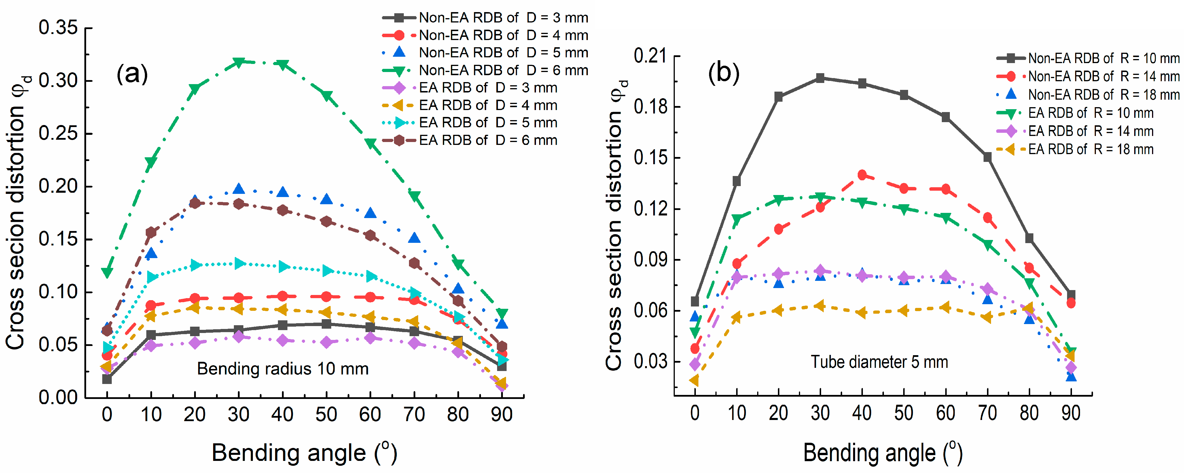
3.2. Size Effects on Bending Defects of Micro-Tube in EA RDB

There are three major bending defects commonly taking place in RDB process, i.e., cross-section distortion, wall thickness variation and wrinkling. In this study, the behaviors of cross-section distortion and wall thickness variation under different process parameters were analyzed except wrinkling. This is because wrinkling is found to play a minor role in bending quality of micro-tubes in EA RDB. Perhaps local Joule heating in the vicinity of the tangential point changes the magnitude and distribution of stress on the cross sections in bending area as shown in Figure 4. Consequently, the difference between the maximum tangent compress stress at the intrados and the maximum tensile stress at the extrados may become smaller, causing the decrease in wrinkling possibility. Due to the radial restriction of the cavity in dies, the cross-section distortion is mainly caused by vertical shrink of the cross section of micro-tube, as shown in Figure 6. Thus, we use the change ratio φ d of the cross section in the vertical direction to evaluate the cross-section distortion of micro-tube, i.e.,
φ d = D D m i n D
where D is the initial diameter of the micro-tube, and D m i n represents the minimum diameter at a certain point after micro-tube bending as shown in Figure 6. Similarly, the wall thickness variation is defined as:
δ t = t t 0 t 0
where t 0 is the initial wall thickness of micro-tube, and t is the minimum or maximum wall thickness on a certain point after bending as shown in Figure 6. Considering the variations in the values of the defects along the bending part, we extracted and calculated the simulation results of cross-section distortion and wall thickness variation of micro-tubes at every 10° along the bending path ranging from 0° to 90° as shown in Figure 6.
The effects of tube diameter and bending radius on the cross-section distortion can be seen in Figure 7. For non-EA RDB, the size effects on the cross-section distortion were found to increase with tube diameter but decrease when bending radius decreases. This is a common result frequently reported in traditional RDB process because the tangential strain at the extrados of micro-tube can be given as D / 2 R , leading to the dependence of the degree of cross-section distortion on the bending radius ratio R / D [21,22]. It is worth noting that the values of cross-section distortion in EA RDB are smaller as compared to those in non-EA case for all the bending angles. For example, the reductions in cross-section distortion of micro-tubes with 3 mm, 4 mm, 5 mm and 6 mm diameters are 2%, 3%, 7% and 14%, respectively, as shown in Figure 7a, when bending the micro-tubes to 90° with 10 mm radius at a speed of 90°/s during the passage of 50 A/mm2 current density. Meanwhile, this current induced reduction is observed to decrease with increasing the bending radius, i.e., 2%, 5% and 7% for R = 18 mm, 14 mm and 10 mm, respectively. These results can be concluded that the size effects (i.e., the tube diameter effect and bending radius effect) on the cross-section distortion tend to be weakened by electrical current in EA RDB of micro-tubes. A possible reason is that the cross-section deformation mainly occurs in the vicinity of tangent point due to local Joule heating as shown in Figure 3, and much smaller deformation may take place on the cross sections next to the local Joule heating area to support the tube wall near the tangent point and avoid distortion. In view of this, the passage of electrical current during RDB has the ability to reduce the degree of cross-section distortion without mandrel or filling material, which may be a simple bending defect control method in RDB, especially suitable for micro-tubes.
The wall thickness variations at different bending angles for 3 mm, 4 mm, 5 mm and 6 mm diameter micro-tubes are compared in Figure 8 between non-EA and EA RDB conditions. As it can be seen, both the thinning at the extrados and the thickening at the intrados of the wall thickness increase with tube diameter in both non-EA and EA RDB processes. This is common since the wall at the extrados is subjected to tensile stress while compressive stress is created at the intrados during the RDB of micro-tube, and the magnitude of these stresses increases with tube diameter [23,24]. Compared to non-EA case, the thickening effect caused by electrical current at the intrados of micro-tube in EA RDB is not obvious, but the passage of electricity during RDB tends to intensify the wall thickness thinning all along the bending path for all the tube diameters. This side effect may be caused by the high sensitivity of EA deformation to tensile stress since local Joule heating can accelerate diffusion necking under tension [25]. Therefore, a reasonable balance of the magnitude of current density is very important in EA RDB of tubes to maximally utilize its beneficial effect but avoid its side effect on bending defect control. Our investigation will be focused on this aspect in future.

3.3. Effect of Electrical Current on RDB Behavior

It is reported that electrical current loading direction plays significant role in EA deformation behavior [26]. In this study, we examined current density and stress distributions in EA RDB under two current passing paths, i.e., die-to-die (Figure 9a) and end-to-end (Figure 9b). For the die-to-die configuration, electrical current would pass from the bend die to the pressure die mainly through the cross sections of micro-tube in the vicinity of the tangential point, while the passage of current follow along the curved micro-tube from one end to another in the end-to-end configuration. As a result, local Joule heating tends to occur near the tangential point in Figure 9a, but in Figure 9b Joule heating expands to nearly all the cross sections along the bending part of micro-tube. As compared to the end-to-end configuration, the die-to-die configuration shows a more uniform distribution of stress with the smaller magnitude, as shown in Figure 9. Then, we obtained the cross-section distortion along the bending part of micro-tubes for the two current passing configurations in EA RDB, as shown in Figure 10. The result reveals the following descending order: EA RDB with end-to-end > Non-EA RDB > EA RDB with die-to-die. Interestingly, the maximum cross-section distortion is about 3 times smaller in die-to-die case (i.e., ~9%) than that in end-to-end case (i.e., ~27.5%). It is known that the nature of tube bending is a localized deformation since the cross-section deformation mainly occurs in the vicinity of the tangent point at every moment. The Joule heating uniformity in the end-to-end configuration cannot guarantee this deformation localization, and continuous softening and deformation take place on most of the cross sections all along the duration of tube bending, causing a significant detrimental effect on cross-section distortion. In contrast, much smaller deformation may occur on the cross sections next to the local Joule heating zone to support the tube wall near the tangent point and avoid cross-section distortion under die-to-die configuration. Therefore, we can conclude that the optimum current loading path in EA RDB could be achieved under the die-to-die configuration since local Joule heating has the ability to reduce the cross-section distortion in micro-tubes. In order to further validate the result, experimental investigation on the effects of bending defect control in EA RDB process under die-to-die configuration would be the priorities of our work in the future. The effects of current density on cross-section distortion and wall thickness variation can be seen in Figure 11. It is found in Figure 11a that the cross-section distortion significantly deceases in EA RDB compared to non-EA RDB, but this reduction slightly increases with current density from 50 A/mm2 to 150 A/mm2. Figure 11b shows that the wall thickness variation at the intrados changes little with current density, but the wall thickness thinning increases with current density at the extrados, leading to the increase in probability of premature cracks at the extrados of micro-tubes. Therefore, a tradeoff faced when controlling the bending defects of micro-tubes is deciding how many current densities to be used in EA RDB. Similar to other EA deformation processes [27,28], a current density threshold would exist in EA RDB as an indicator of the current induced side effect exceeding beneficial effect on the bending quality of micro-tubes. Further investigation would focus on this behavior for various sized tubes of different materials.

4. Conclusions

In this study, 3D FE modeling and simulation of EA RDB process for 6063 aluminum alloy micro-tube was conducted. The evolution of the coupling physical fields and the influences of different process parameters on cross-section distortion and wall thickness variation were analyzed based on the simulation results of EA RDB for micro-tubes. The main conclusions can be given as follows:
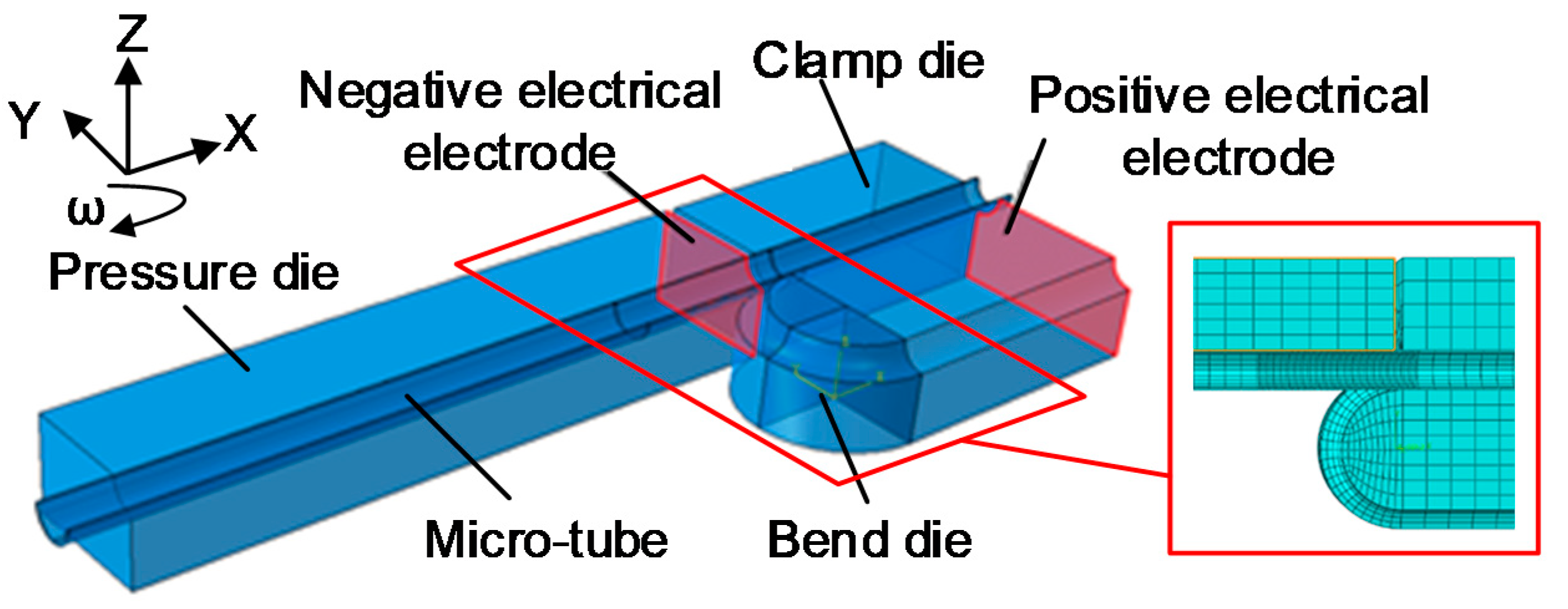
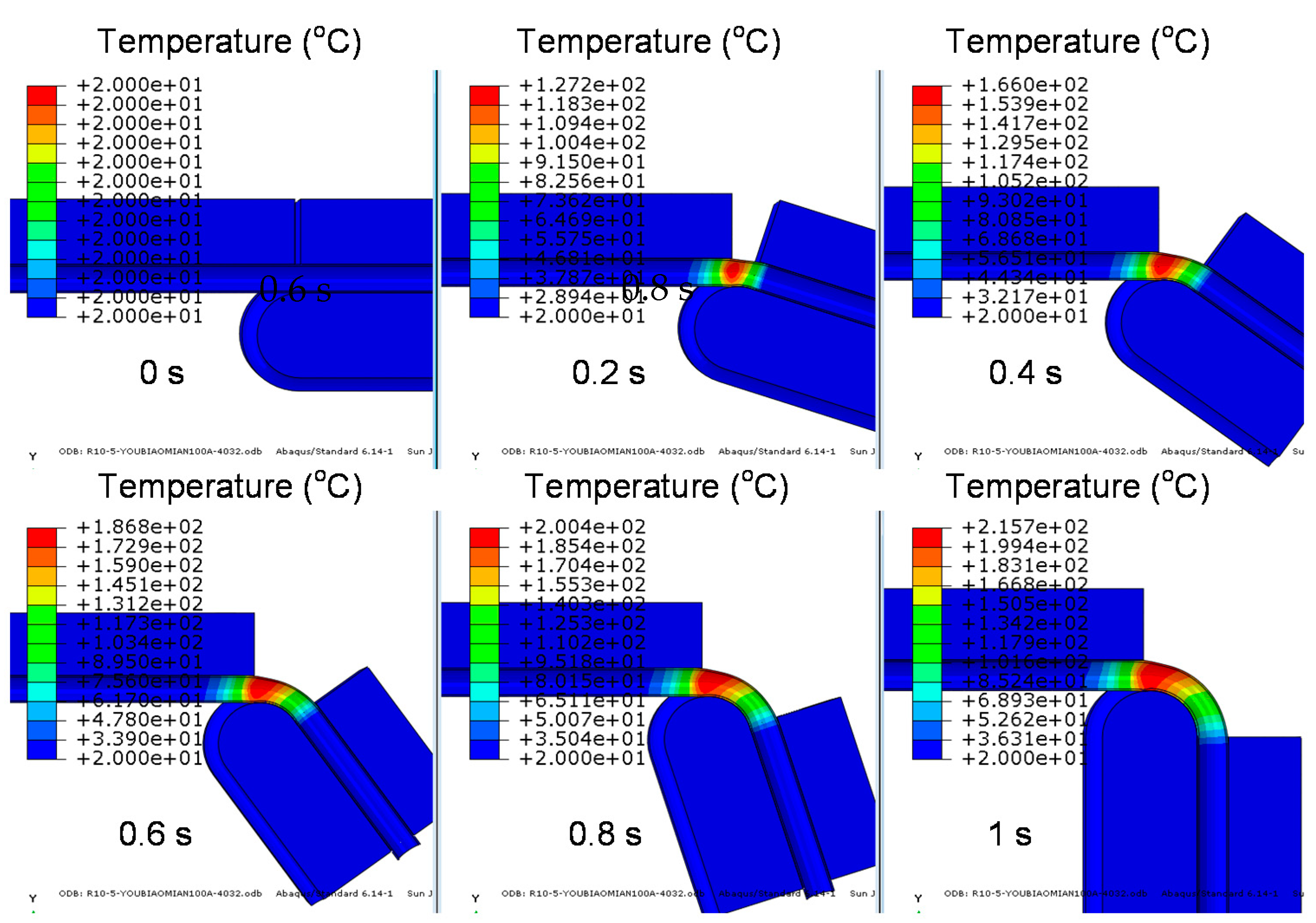
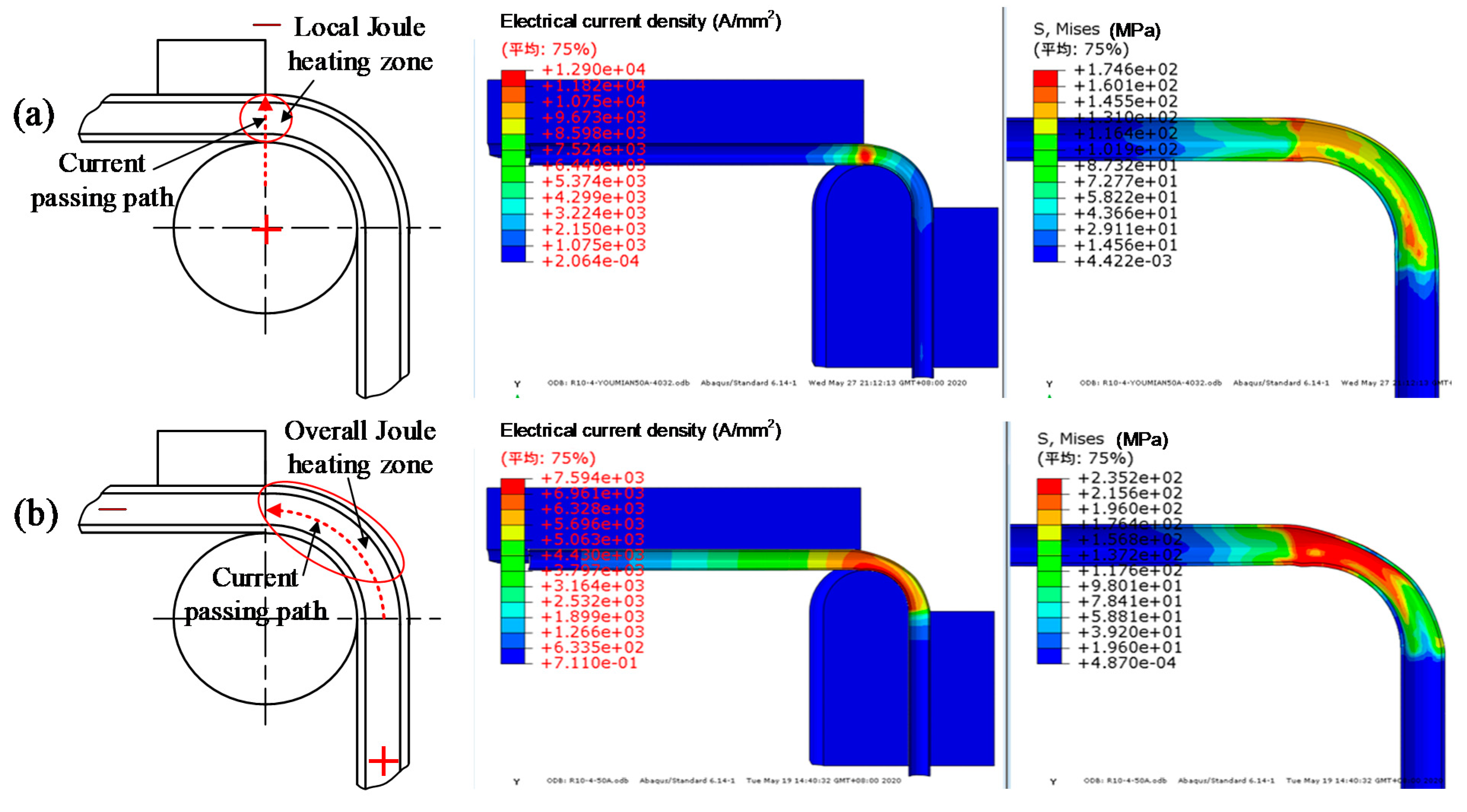
  • Electrical current passing path significantly affected the EA RDB behavior, causing the maximum cross-section distortion in die-to-die configuration ~3 times smaller than that in end-to-end case. The optimum current loading path in EA RDB could be achieved under the die-to-die configuration since micro-tubes were locally heated in the vicinity of the tangential point due to the concentrated distribution of current density throughout the duration of EA RDB, which is exactly on the cross sections where bending deforming mainly occurred.
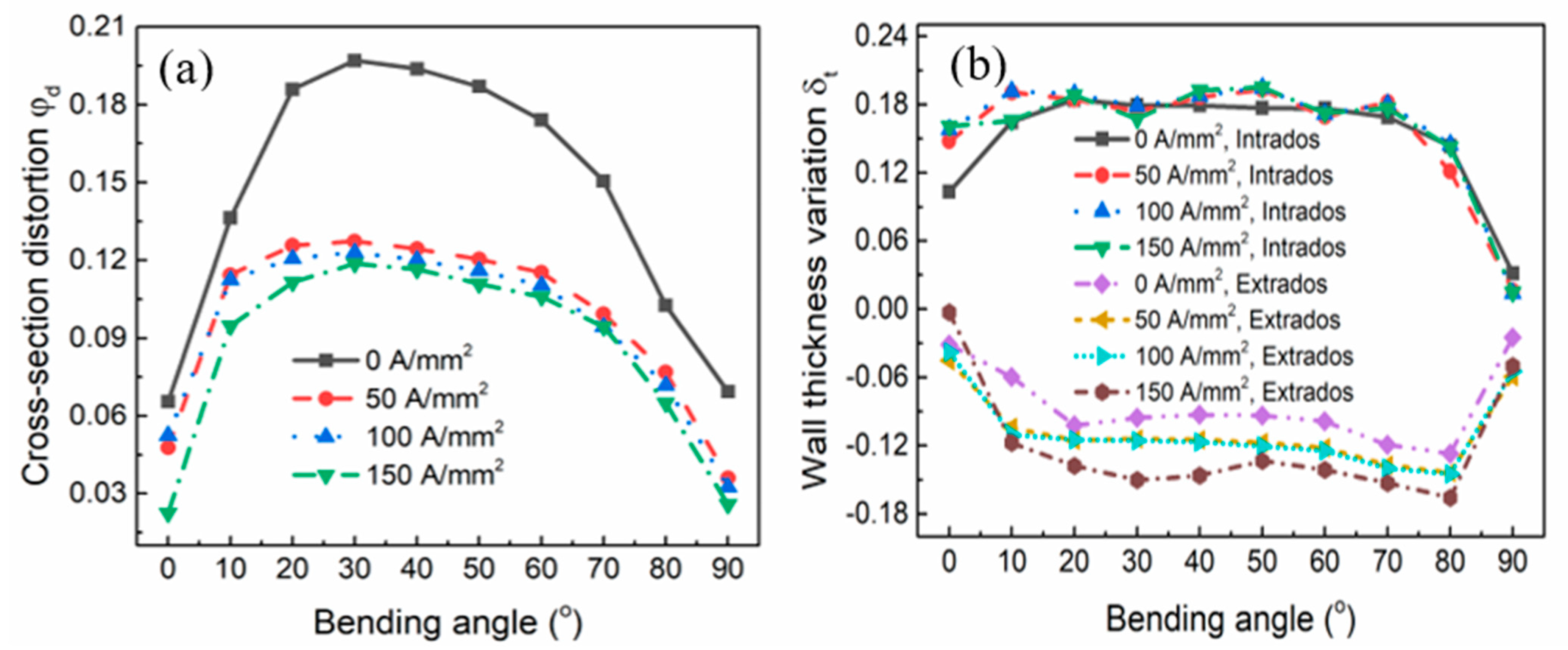
  • The effects of tube diameter and bending radius on the cross-section distortion (i.e., the larger tube diameter and the smaller bending radius leading to the higher cross-section distortion) tend to be weakened by electrical current in EA RDB of micro-tubes.
  • The thickening effect caused by electrical current at the intrados of micro-tube in EA RDB is not obvious, but the passage of electricity during RDB tends to enhance the wall thickness thinning all along the bending path for all the tube diameters as compared to non-EA case.
  • Increasing current density from 50 A/mm2 to 150 A/mm2 can slightly reduce the degree of cross-section distortion, but resulted in the increase of wall thickness thinning at the extrados. Therefore, a current density threshold may exist in EA RDB in terms of the tradeoff of current density between the reduction in cross-section distortion and the over-thinning of wall thickness in micro-tubes.

Author Contributions

Conceptualization, J.X. and B.G.; methodology, X.W.; software, M.D.; validation, X.W. and M.D.; formal analysis, X.W.; investigation, M.D.; resources, J.X. and B.G.; data curation, X.W. and M.D.; writing—original draft preparation, X.W.; writing—review and editing, Y.Z.; visualization, X.W.; supervision, Z.W.; project administration, D.S.; funding acquisition, X.W. and B.G. All authors have read and agreed to the published version of the manuscript.

Funding

The authors would like to thank the National Natural Science Foundation of China (No. 51705101), the Heilongjiang Provincial Natural Science Foundation of China (No. YQ2020E014) and the China Postdoctoral Science Foundation (No. 2018T110293) for the financial support given to this study.

Institutional Review Board Statement

Not applicable.

Informed Consent Statement

Not applicable.

Data Availability Statement

Not applicable.

Conflicts of Interest

The authors declare no conflict of interest.

References

  1. Baturkin, V. Micro-satellites thermal control—Concepts and components. Acta Astronaut. 2005, 56, 161–170. [Google Scholar] [CrossRef] [Green Version]
  2. Vasiliev, L.L. Micro and miniature heat pipes—Electronic component coolers. Appl. Therm. Eng. 2008, 28, 266–273. [Google Scholar] [CrossRef]
  3. Narendran, N.; Gu, Y.; Freyssinier, J.P.; Yu, H.; Deng, L. Solid-state lighting: Failure analysis of white LEDs. J. Cryst. Growth 2004, 268, 449–456. [Google Scholar] [CrossRef]
  4. McGlen, R.J.; Jachuck, R.; Lin, S. Integrated thermal management techniques for high power electronic devices. Appl. Therm. Eng. 2004, 24, 1143–1156. [Google Scholar] [CrossRef]
  5. Wang, X. Study of Wrinkling Defects in Bending Thin-Walled Micro-Heat Pipes. Master’s Thesis, South China University of Technology, Guangzhou, China, 2012. [Google Scholar]
  6. Huang, D. Study of Forming Defects in Bending Micro-Heat Pipe with Micro-Grooves. Master’s Thesis, South China University of Technology, Guangzhou, China, 2010. [Google Scholar]
  7. Heng, L.; He, Y.; Zhiyong, Z.; Zekang, W. ‘Size effect’ related bending formability of thin-walled aluminum alloy tube. Chin. J. Aeronaut. 2013, 26, 230–241. [Google Scholar] [CrossRef] [Green Version]
  8. Wang, X.; Xu, J.; Jiang, Z.; Zhu, W.-L.; Shan, D.; Guo, B.; Cao, J. Size effects on flow stress behavior during electrically-assisted micro-tension in a magnesium alloy AZ31. Mater. Sci. Eng. A-Struct. Mater. Prop. Microstruct. Process. 2016, 659, 215–224. [Google Scholar] [CrossRef] [Green Version]
  9. Fan, R.; Magargee, J.; Hu, P.; Cao, J. Influence of grain size and grain boundaries on the thermal and mechanical behavior of 70/30 brass under electrically-assisted deformation. Mater. Sci. Eng. A-Struct. Mater. Prop. Microstruct. Process. 2013, 574, 218–225. [Google Scholar] [CrossRef]
  10. Xie, L.; Guo, H.; Song, Y.; Liu, C.; Wang, Z.; Hua, L.; Wang, L.; Zhang, L.-C. Effects of electroshock treatment on microstructure evolution and texture distribution of near-beta titanium alloy manufactured by directed energy deposition. Mater. Charact. 2020, 161, 110137. [Google Scholar] [CrossRef]
  11. Stolyarov, V.V. Features of Deformation Behavior at Rolling and Tension under Current in TiNi Alloy. Rev. Adv. Mater. Sci. 2010, 25, 194–202. [Google Scholar]
  12. Stolyarov, V.; Calliari, I.; Gennari, C. Features of the interaction of plastic deformation and pulse current in various materials. Mater. Lett. 2021, 299, 130049. [Google Scholar] [CrossRef]
  13. Zhao, Y.; Peng, L.; Lai, X. Influence of the electric pulse on springback during stretch U-bending of Ti6Al4V titanium alloy sheets. J. Mater. Process. Technol. 2018, 261, 12–23. [Google Scholar] [CrossRef]
  14. Jordan, A.; Kinsey, B.L. Investigation of thermal and mechanical effects during electrically-assisted microbending. J. Mater. Process. Technol. 2015, 221, 1–12. [Google Scholar] [CrossRef]
  15. Ao, D.; Chu, X.; Yang, Y.; Lin, S.; Gao, J. Effect of electropulsing on springback during V-bending of Ti-6Al-4V titanium alloy sheet. Int. J. Adv. Manuf. Technol. 2018, 96, 3197–3207. [Google Scholar] [CrossRef]
  16. Zhu, H.; Qin, C.; Wang, J.Q.; Qi, F.J. Characterization and Simulation of Mechanical Behavior of 6063 Aluminum Alloy Thin-walled Tubes. Adv. Mater. Res.-Switz. 2011, 197–198, 1500–1508. [Google Scholar]
  17. Rajput, D.; Singh, A.; Kumar, S. Evaluation of Johnson-Cook Material Model Parameters of AA6063-T6. Int. Res. J. Eng. Technol. 2020, 07, 1476–1481. [Google Scholar]
  18. Ruszkiewicz, B.J.; Grimm, T.; Ragai, I.; Mears, L.; Roth, J.T. A Review of Electrically-Assisted Manufacturing with Emphasis on Modeling and Understanding of the Electroplastic Effect. J. Manuf. Sci. Eng.-Trans. Asme 2017, 139, 110801. [Google Scholar] [CrossRef]
  19. Ding, Y. Research on Hot Bending Forming without Mould of BR1500HS High-Strength Streel Tube. Master’s Thesis, Harbin Institute of Technology, Harbin, China, 2016. [Google Scholar]
  20. Chen, X. Finite Element Simulation for Axis-Thrust Bending Process of Thin-Walled Tube. Master’s Thesis, Yanshan University, Qinhuangdao, China, 2006. [Google Scholar]
  21. Liu, Y.; Daxin, E. Effects of Cross-Sectional Ovalization on Springback and Strain Distribution of Circular Tubes Under Bending. J. Mater. Eng. Perform. 2011, 20, 1591–1599. [Google Scholar] [CrossRef]
  22. Li, H.; Yang, H.; Zhan, M.; Kou, Y.L. Deformation behaviors of thin-walled tube in rotary draw bending under push assistant loading conditions. J. Mater. Process. Technol. 2010, 210, 143–158. [Google Scholar] [CrossRef]
  23. Zhao, G.Y.; Liu, Y.L.; Yang, H.; Lu, C.H.; Gu, R.J. Three-dimensional finite-elements modeling and simulation of rotary-draw bending process for thin-walled rectangular tube. Mater. Sci. Eng. A 2009, 499, 257–261. [Google Scholar] [CrossRef]
  24. Zhang, Q.; Tang, D.; Li, D.; Peng, Y. Numerical and experimental study on in-plane bending of microchannel aluminum flat tube. J. Mater. Process. Technol. 2010, 210, 1876–1884. [Google Scholar] [CrossRef]
  25. Wang, X.W.; Xu, J.; Shan, D.B.; Guo, B.; Cao, J. Modeling of thermal and mechanical behavior of a magnesium alloy AZ31 during electrically-assisted micro-tension. Int. J. Plast. 2016, 85, 230–257. [Google Scholar] [CrossRef] [Green Version]
  26. Ma, Y.R.; Yang, H.J.; Ben, D.D.; Shao, X.H.; Tian, Y.Z.; Wang, Q.; Zhang, Z.F. Anisotropic Electroplastic Effects on the Mechanical Properties of a Nano-Lamellar Austenitic Stainless Steel. Acta Metall. Sin.-Engl. Lett. 2021, 34, 534–542. [Google Scholar] [CrossRef]
  27. Chu, X.R.; Wang, L.; Lin, S.X.; Yue, Z.M.; Gao, J. Experimental Investigation on Formability of AZ31B Magnesium Alloy V-Bending Under Pulse Current. Acta Metall. Sin.-Engl. Lett. 2018, 31, 1249–1257. [Google Scholar] [CrossRef] [Green Version]
  28. Adams, D.; Jeswiet, J. Single-point incremental forming of 6061-T6 using electrically assisted forming methods. Proc. Inst. Mech. Eng. Part B-J. Eng. Manuf. 2014, 228, 757–764. [Google Scholar] [CrossRef]
Figure 1. The three-dimensional (3D) finite-elements (FE) model of electrically-assisted rotary-draw bending (EA RDB) process of micro-tube.
Metals 11 01956 g001
Figure 2. Evolution of current density distribution with time in micro-tube when 50 A/mm2 passing through the side surface of bend die in EA RDB process: (a) 0 s, (b) 1 × 10⁻⁵ s, (c) 0.5 s, (d) 1 s.
Metals 11 01956 g002
Figure 3. Evolution of Joule heating temperature distribution with time in micro-tube during EA RDB process.
Metals 11 01956 g003
Figure 4. Variation of Mises stress distribution with time in (a) non-EA and (b) EA RDB process of micro-tube with 5 mm diameter and 10 mm bending radius.
Metals 11 01956 g004
Figure 5. Variation of equivalent strain distribution with time in (a) non-EA and (b) EA RDB process of micro-tube with 5 mm diameter and 10 mm bending radius.
Metals 11 01956 g005
Figure 6. Schematic diagram of micro-tube RDB and bending defects.
Metals 11 01956 g006
Figure 7. The influence of (a) tube diameter and (b) bending radius on cross-section distortion in non-EA RDB and EA RDB.
Metals 11 01956 g007
Figure 8. Wall thickness variation at different bending angles in non-EA and EA RDB with 10 mm bending radius of different micro-tube diameters: (a) 3 mm, (b) 4 mm, (c) 5 mm, (d) 6 mm.
Metals 11 01956 g008
Figure 9. A comparison of current density and stress distributions under different electrical current passing path in EA RDB: (a) die-to-die, (b) end-to-end.
Metals 11 01956 g009
Figure 10. Cross section distortion at different bending angles of micro-tubes for different current passing configurations in RDB.
Metals 11 01956 g010
Figure 11. Effects of current density on (a) cross-section distortion and (b) wall thickness variation at different bending angles in EA RDB of micro-tubes.
Metals 11 01956 g011
Table 1. Parameters of Johnson-Cook model for 6063 aluminum alloy.
A (Mpa)B (Mpa)nCm
176.4563.990.070.00361.003
Note: the value of m was obtained from [17], and the other constants used the values in [16].
Table 2. Parameters used for the simulation of EA RDB process.
ParametersValue
Tube diameter (mm)3, 4, 5, 6
Tube thickness (mm)0.3
Bending radius (mm)10, 14, 18
Bending angle (°)90
Current density (A/mm2)0, 50, 100, 150
Table 3. The material properties of micro-tubes and dies.
Part Density ρ
(kg/m3)
Young’s Modulus E
(Gpa)
Poisson’s Ratio v Thermal Conductivity k
(W/m/°C)
Specific Heat c
(J/kg/°C)
Electrical Conductivity σ e
(S/mm)
Micro-tubes270066.70.3311990034,800
Dies78502100.344.54754032
Publisher’s Note: MDPI stays neutral with regard to jurisdictional claims in published maps and institutional affiliations.

