Article

Analysis of Dynamic Response Behavior of Crack under Impact Stress Wave

National Engineering Research Center for Equipment and Technology of Cold Rolled Strip, Yanshan University, Qinhuangdao 066004, China
*
Author to whom correspondence should be addressed.
Metals 2021, 11(12), 1920; https://doi.org/10.3390/met11121920
Submission received: 31 October 2021 / Revised: 20 November 2021 / Accepted: 25 November 2021 / Published: 28 November 2021
(This article belongs to the Section Metal Failure Analysis)

Abstract

:
The structural parts of construction machinery mostly fail due to impact load, but current research on the failure behavior of the impact load has not established a complete theoretical system. Based on wave theory and fracture mechanics, this paper analyzed the wave behavior of shock stress waves and established a model of shock stress wave propagation. Given the dynamic response behavior of the stress and strain field at the crack tip, dynamic fracture mechanics theory was used to solve the dynamic fracture strength stress factor and evaluate the dynamic fracture performance of the structure with crack damage under shock waves. Through dynamic response analysis and numerical calculation of the typical SHPB (split Hopkinson pressure bar) test standard compact tension (CT) specimens under the short-term strong shock stress wave, the stress and strain evolution law of the material under the shock wave was analyzed, and the correlation of the shock stress wave was verified. This research work can meet the requirements of engineering design and has practical engineering significance, playing an important role in material safety design.

1. Introduction

In modern industry, the service conditions of engineering components are becoming more and more complex. Given the dynamic response and failure characteristics of structures under dynamic loads, such as impact loads, traditional mechanical performance indicators are insufficient to reflect the service characteristics of engineering components. Therefore, there is an urgent need to study the dynamic mechanical behavior of materials. At the same time, under the action of impact load (the inertial effect cannot be ignored), the service performance of damaged metal materials becomes very complicated [1,2]. Therefore, the in-depth study of the dynamic response behavior and failure characteristics of metal materials under impact loads has become the frontier of current scientific research [3]. In addition to static load, various structures are often involved in dynamic loads such as impact and explosion during their work and use. Generally, an impact load has a very short-acting time, fast speed, and high strain rate. Therefore, the propagation of stress waves and the dynamic response behavior of the structure under the impact load has an extremely important influence on the safety and reliability of the components [4,5,6,7,8]. When the metal material is subjected to an external impact load, the wave will propagate outward from the impact area, and the shock wave will pass through the material and cooperate with the boundary [9,10,11,12]. Since the shock stress wave will contain the physical properties and mechanical properties of the metal component materials, the stress wave propagation method is widely used in various engineering fields. The propagation behavior of stress waves provides the main means for non-destructive testing of defects and inhomogeneities in opaque materials and is the only means to study the response of materials under different conditions [13]. Therefore, the study of stress wave propagation helps in understanding the behavior of materials when subjected to impact loads or collisions [14]. At the same time, modeling and numerical simulation analysis of the amplitude, velocity, and impedance of the shock stress wave show that the stress wave propagation method provides the best solution for studying the behavior of materials under shock loads [13,15,16,17]. Consequently, the establishment of an effective model of stress wave propagation to accurately characterize the behavior of strain waves is extremely important for the safety design of structural materials against impact and the reliability of service.
The wave equation is one of the 17 equations that “change the world”, and it plays an important role in mechanics [18]. The mathematical description of wave phenomena is not only the basis of mechanics but also the basis of many other fields of physics. The classical wave equation is the cornerstone of mathematical physics and mechanics, widely used to describe wave phenomena [19,20,21]. Since the shock load has the characteristics of significant load changes on a short time scale [22,23,24], the shock stress wave is mainly concerned with the non-uniform and unsteady movement of the medium that changes continuously with coordinates and time, focusing on the local effect of the shock load on the medium and early stages. Stress wave analysis focuses on the coupling between the load and the medium, and the close relationship between the stress wave and the dynamic mechanical properties of the material [25,26].
The propagation law of stress waves in crack defects is one of the hot spots in the field of engineering [27]. Considering the mutual coupling effect of stress and strain fields in the crack tip area during the propagation of shock stress waves, it is very important to establish a model that can characterize the propagation of stress waves at the crack [28,29]. On this basis, the mechanical behavior of cracks under impact load and the propagation law of stress waves near the cracks are studied [30,31,32,33]. Aimed at the linear elastic dynamic fracture characteristics of the material, a dynamic analysis method of the dynamic crack initiation and propagation process under stress wave load was established [34,35]. To characterize the dynamic response of the crack tip, the dynamic energy release rate under dynamic loading was proposed to describe the dynamic mode of crack propagation [36]. At the same time, using incident wave shaping technology and force sensor technology, a calculation method for determining dynamic stress intensity factors was proposed [37]. However, a method for accurately evaluating the dynamic response of zero components under impact load and the construction of a unified theoretical system for impact failure research are difficult points in impact research.
The shock wave equation was the cornerstone of mathematics, physics, and mechanics. Stress wave propagation behavior had extremely important scientific research value and practical engineering significance for the evaluation of the service performance of metal materials containing cracks [38]. Based on wave theory and the characterization method of the traced stress wave behavior, the paper established the shock stress wave propagation model. Aimed at the dynamic response behavior of the stress and strain field at the crack tip, the dynamic fracture strength stress factor was introduced to evaluate the dynamic fracture performance of the crack-damaged structure under shock wave action. Finally, using the SHPB test data analysis of the compact tensile specimens and the numerical simulation analysis of the Abaqus finite element combination, the evolutionary behavior of the stress–strain field under the shock stress wave and the fracture toughness of the cracked component were characterized. The interaction between the propagation behavior of stress waves and the dynamic evolution of cracking was analyzed.

2. Stress Wave Propagation Equation in Metal

A stress wave is a state that enters another state at a finite speed and belongs to a type of disturbance wave without giving the medium as a whole any permanent displacement [39,40]. Therefore, waves can occur in media in which energy can be stored in both kinetic and potential forms [11]. The physical process can be better simulated by modifying the classical wave equation. In this section of the paper, the general stress wave model is introduced in detail, and the evolution equation controlling single-wave distortion is described. At the same time, a characterization method for the evolution of the stress and strain field at the tip of the crack under the action of the shock stress wave is constructed.

2.1. Wave Equation of Material under Stress Wave

In solid media, different types of elastic–plastic waves can propagate. The types and properties of the waves mainly depend on the relationship between the direction of particle motion and the direction of wave propagation, in addition to the boundary conditions. A “particle” can be regarded as a tiny discrete part of a solid, but it is not an atom, because a particle is a combination of many atoms, and atoms can move irregularly in the particle. Relevant characteristics are confirmed by the literature [41]. There are different kinds of stress waves that can propagate through a material.
Stress waves are characterized by the motion of the particles in the material [42]. In a solid, when the propagation direction of the wave is parallel to the motion direction of particle, it is called a longitudinal wave or pressure wave ( P -wave). If the motion direction of the particle is perpendicular to the propagation direction of the wave itself, it is called a shear wave ( S -wave; also known as a distorted wave, transverse wave or isochoric wave), and the solid surface can move upward, downward, vertical, or backward. Forward-moving waves are called surface waves (Rayleigh waves). In a solid medium, the velocity of the surface wave is the slowest, and the velocity of a longitudinal wave is the fastest, which are confirmed by the literature [43]. The amplitude changes of a longitudinal wave, shear wave, and surface wave in half-space coordinates are shown in Figure 1 [44].
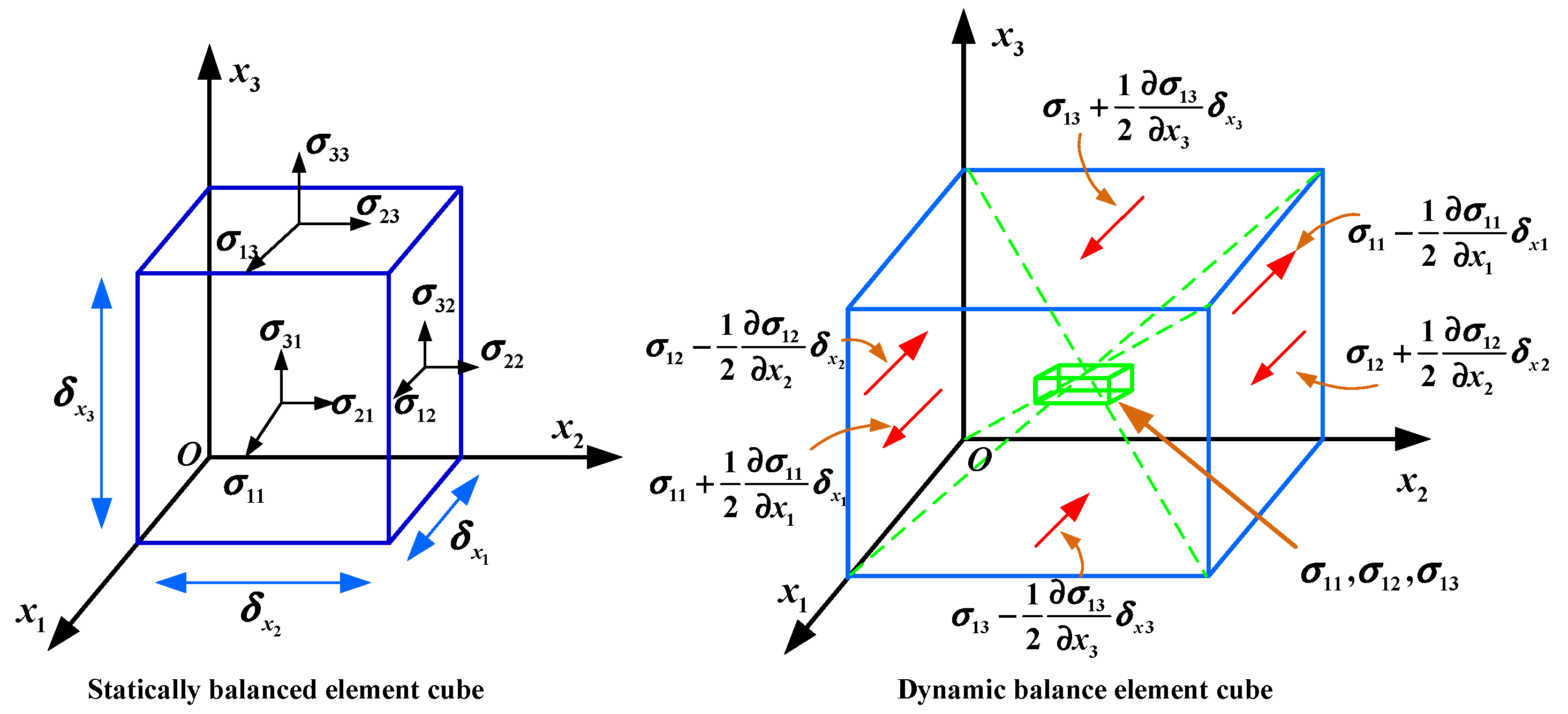
P- and S-waves are reflected by stress-free boundaries and by internal defects of sufficient size. In a P -wave, the amplitude of the displacements is maximum at the centerline of the plate and decreases to zero at the surface. In an S -wave, the amplitude of displacements is zero at the centerline of the plate and the surface and is maximum along a ray located approximately 40 degrees from the centerline. In all types of waveforms, the surface wave transmits 67% of the total energy, the shear wave transmits 26% of the total energy, and the compression wave transmits 7% of the total energy [45]. The cube element with infinitesimal elements in the solid is in the state of dynamic equilibrium, that is, static non-equilibrium. The stress acting on the opposite surface will not be equal, and its elastic–plastic wave propagation equation in the continuum will be solved by solving the force acting on the infinitesimal elements (see Figure 2).
The stress equation of each principal stress direction in the element is:
{ σ 11 x 1 + σ 12 x 2 + σ 13 x 3 = ρ 2 u 1 t 2 σ 21 x 1 + σ 22 x 2 + σ 23 x 3 = ρ 2 u 2 t 2 σ 31 x 1 + σ 32 x 2 + σ 33 x 3 = ρ 2 u 3 t 2
where u i is displacement, σij is the stress, ρ is density, and xi is direction displacement of space principal coordinate.
By solving the second-order partial differential equation, the wave propagation equation of various pulse waves can be solved.
{ x ( E u x ) = ρ 2 u t 2 μ 2 x i x j ( u i x k u k x i ) = ρ t 2 ( u i x k u k x i ) ( λ + 2 μ ) 2 Δ x i x j = ρ 2 Δ t 2
The velocity of P-wave, shear wave, and surface wave (CL, CS) are obtained by:
{ c l = 1 2 Δ λ + 2 μ ρ = 1 v ( 1 + v ) ( 1 2 v ) E ρ = 2 G ( 1 v ) ρ ( 1 2 v ) c S = μ ρ = E 2 ρ ( 1 + v ) = G ρ c R = 0.862 + 1.14 v 1 + v μ ρ
where λ = v E / [ ( 1 + v ) ( 1 2 v ) ] , G is the shear modulus, v is Poisson’s ratio, and μ is the shear modulus.
Under the action of the stress wave, the general solution of the material wave equation is:
u ( x , t ) = F ( x C 0 t ) + G ( x ) + C 0 ( t )
where F and G describe the pulse waveforms propagating in the positive and negative directions, respectively, at velocity C0.
In the process of one-dimensional stress wave propagation, the expression of stress wave is as follows:
u ( x , t ) = f ( x + c t ) + g ( x c t ) = { A e ± a x e i ( w t ± κ x ) Time domain A e i ( w t f 1 x ) + B e i ( w t ± f 1 x ) Frequency domain

2.2. Crack Dynamic Response under İmpact Load

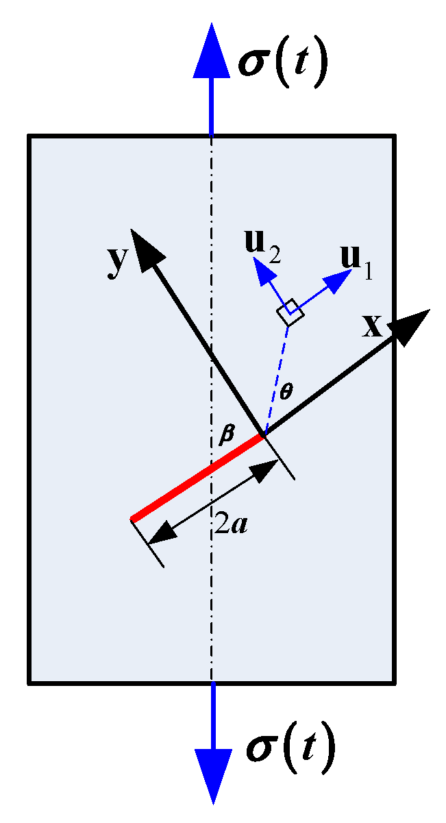
The crack tip stress and displacement fields are the basis of fracture analysis. There is a I/II mixed-mode (see Figure 3) fracture during crack propagation. According to Chen–Sih fracture analysis [46], the expressions of stress and displacement fields at the crack tip under dynamic loading are similar to expressions under quasi-static conditions, that is, the linear elastic displacement component at the crack tip is:
{ u 1 ( r , θ , t ) = K I 4 μ r 2 π [ ( 2 k 1 ) cos θ 2 cos 3 θ 2 ] + K II 4 μ r 2 π [ ( 2 k + 3 ) sin θ 2 + sin 3 θ 2 ] u 2 ( r , θ , t ) = K I 4 μ r 2 π [ ( 2 k + 1 ) sin θ 2 sin 3 θ 2 ] K II 4 μ r 2 π [ 2 ( k 1 ) sin θ 2 + cos 3 θ 2 ] u 3 = { 0 p l a i n   s t r a i n v E [ σ x ( r , θ , t ) + σ y ( r , θ , t ) ] d z p l a i n   s t r e s s
where k is 3 4 v for plain strain or ( 3 v ) / ( 1 + v ) for plane stress.
There is a certain range of plastic zone at the crack tip. Under an impact load, the size of the plastic zone at the crack tip will change with the change of the load. According to the analysis of elastoplastic materials [47], the size of the plastic zone under impact load is:
r t i p = { 1 2 π ( K C d y n σ y ) 2 plane stress 1 2 π ( ( 1 2 v ) K C d y n σ y ) 2 plane strain
where r t i p is the size of the plastic zone.
Maximum circumferential tensile stress preparation is used to analyze the crack propagation. Because the crack cracks along the direction of the maximum circumferential tensile stress intensity factor, when the maximum circumferential tensile stress intensity factor reaches the critical value, the crack instability propagation can be obtained.
{ K θ d y n ( t ) = cos θ 2 [ K I d y n ( t ) 2 ( 1 + cos θ ) 3 K II d y n ( t ) 2 sin θ ] K θ d y n ( t ) θ | θ = θ 0 = 0 2 K θ d y n ( t ) θ 2 | θ = θ 0 < 0
The crack propagation direction under the action of impact stress wave is:
θ = 2 a tan [ 1 4 ( K I d y n ( t ) K II d y n ( t ) sign ( K II d y n ( t ) ) [ ( K I d y n ( t ) K II d y n ( t ) ) 2 + 8 ] 1 / 2 ) ]
where θ is the crack angle, and K I d y n ( t ) and K II d y n ( t )   are the dynamic fracture factors of mode I and II, respectively.

3. Numerical Simulation Process and Result Analysis

The numerical simulation of the dynamic instability of crack propagation in structures is challenging work. When the traditional finite element method is used to simulate crack propagation, mesh reconstruction needs to be carried out continuously [48]. For the three-dimensional problem, the calculation scale is difficult to accept. A modified finite element method, named the extended finite element method (XFEM), is proposed to simulate discontinuity problems. The core idea of XFEM is to add function terms with discontinuity characteristics to the displacement approximation function to simulate the characteristics of discontinuity. The level set function is used to describe the location and characteristics of the discontinuity interface so that the description of discontinuity can be independent of the finite element mesh. Therefore, the XFEM method can simulate crack propagation along any path without mesh reconstruction.

3.1. Establishment of Finite Element Model

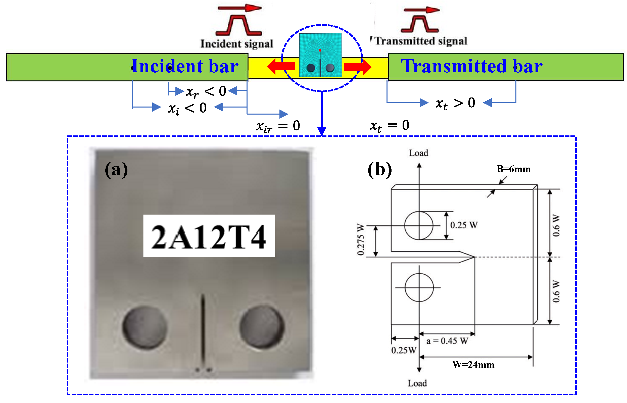
Numerical simulation of the impact failure process of 2A12T4 aluminum alloy was carried out using the extended finite element method. Based on commercial finite element software ABAQUS technology, the SHPB [49] experiment (see Figure 4) for compact tension specimens (CT sample, W = 24   mm , a = 10.8   mm , b = 6   mm ) was carried out, and the stress fluctuation diagram was obtained at different times to determine the fracture time of the CT specimen. The propagation finite element model of aluminum alloy was established, and the numerical simulation analysis of the failure process was carried out using the extended finite element method (XFEM). By comparison with the experimental results, the dynamic crack propagation process and dynamic failure law of the 2A12T4 aluminum alloy were studied. Over recent years, the dynamic tensile fracture of materials has gradually become the forefront of scientific research, but there is not yet a unified standard and evaluation criteria for dynamic fracture. As the crack propagation problem is strongly discontinuous and nonlinear, the convergence of iterative calculation is more difficult.
A three-dimensional eight node continuum element (C3D8R) was used to simulate 2A12T4 aluminum alloy, showing that the strain rate hardening effect was insignificant [50,51]. The stress–strain behavior of 2A12 aluminum alloy (see Table 1) has been fully studied [52]. The ABAQUS finite element package was used to carry out the analysis [53]. The basic material parameters are presented in Table 2.
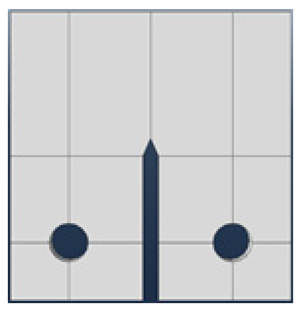
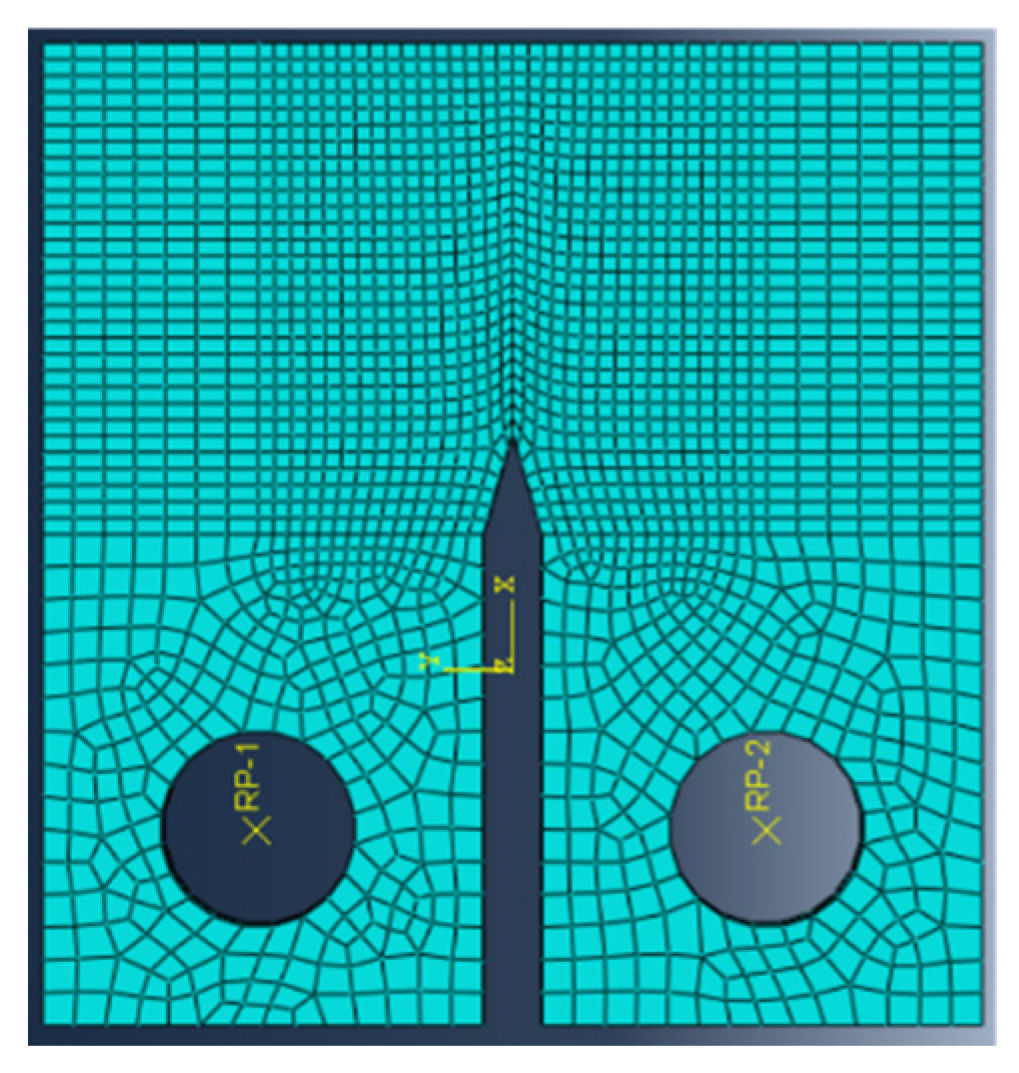
The geometric model of the compact tensile specimen was constructed, and is presented in Figure 5. Through scanning and mapping, the finite element model after meshing is presented in Figure 6. The grid size and layout in the finite element directly determined the accuracy of the simulation results. Therefore, it was best to use as much elemental analysis as possible. However, the analysis of a large number of elements would require too much computer time. Therefore, for best results without excessive computer use, the closer to the hole, the finer the mesh. As such, the 3D mesh generation of the finite element model was created by sweeping and mapping. To improve the simulation accuracy, mesh optimization of different units in the structural modeling was carried out. After gridding, there were 18304 cells for the perforated plate and 8544 cells for the mandrel area.
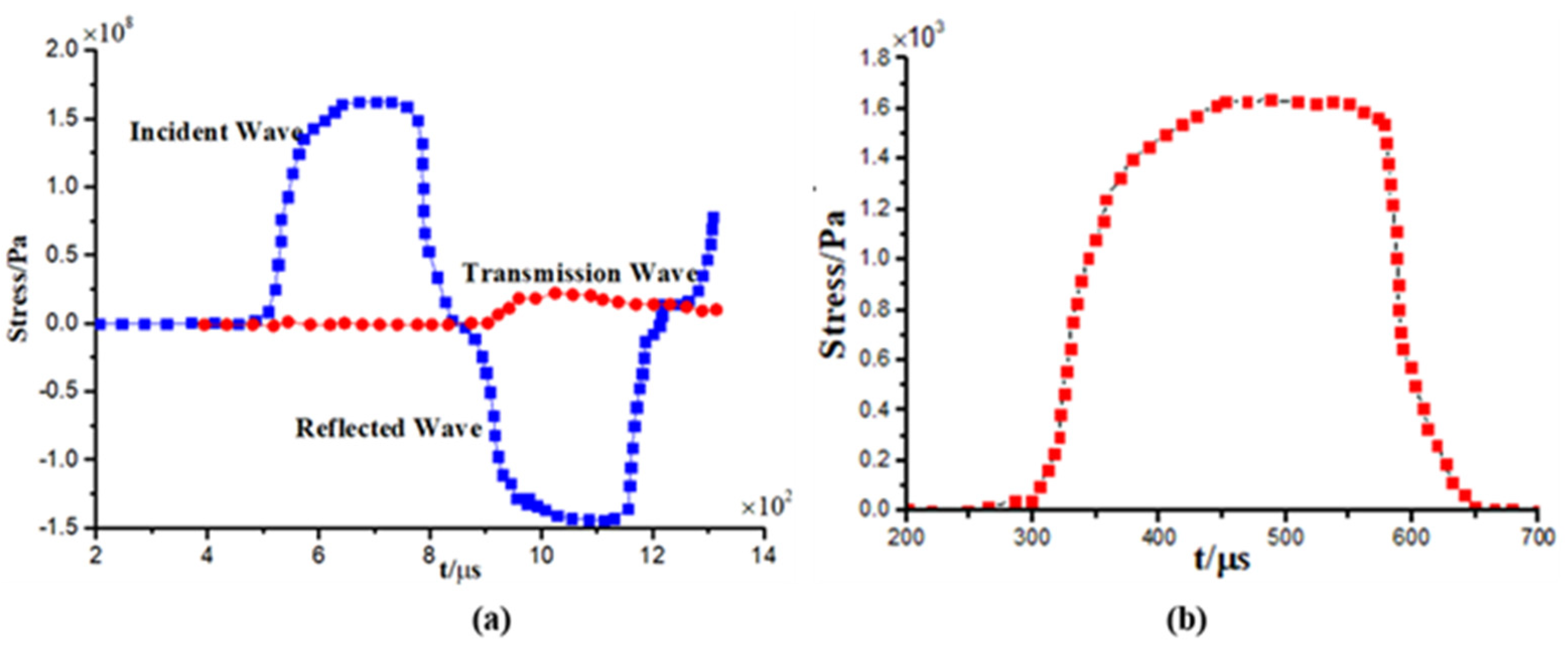
The waveform data of shock loading was obtained by the SHPB experimental system, and the incident waveform curve was obtained by filtering, smoothing and waveform trimming technology [54], as presented in Figure 7.
In dynamic fracture mechanics, the dynamic stress intensity factor K I ( t )   of material is expressed as:
K I ( t ) = lim r 0 2 π r σ y y ( r , 0 , t )
In linear elastic fracture mechanics, the stress and displacement at the crack tip are expressed as:
{ σ x = K I 2 π r cos θ 2 ( 1 sin θ 2 sin 3 θ 2 ) K II 2 π r sin θ 2 ( 2 + cos θ 2 cos 3 θ 2 ) σ y = K I 2 π r cos θ 2 ( 1 + sin θ 2 sin 3 θ 2 ) + K II 2 π r sin θ 2 cos θ 2 cos 3 θ 2 σ z = { 0 plate stress 2 ν K I 2 π r cos θ 2 2 ν K II 2 π r sin θ 2 plate strain τ x y = K I 2 π r cos θ 2 sin θ 2 cos 3 θ 2 + K II 2 π r cos θ 2 ( 1 sin θ 2 sin 3 θ 2 )

3.2. Dynamic Stress intensity factor

The calculation formula of stress intensity factor K q for compact tensile specimen is expressed as:
K q = P q B W ( 2 + a / W ) ( 0.886 + 4.64 a / W 13.32 a 2 / W 2 + 14.72 a 3 / W 3 5.6 a 4 / W 4 ) ( 1 a / W ) 3
where B is the CT sample thickness, W is the CT sample width, and a is the crack length.
Assuming that the stress-intensity factor is still proportional to the displacement in the vicinity of the crack tip under dynamic loading, Kishimoto [55] derived a simple formula for calculating the dynamic stress-intensity factor for the first time. Therefore, the dynamic stress intensity factor KI(t) is expressed as:
K q = P q B W ( 2 + a / W ) ( 0.886 + 4.64 a / W 13.32 a 2 / W 2 + 14.72 a 3 / W 3 5.6 a 4 / W 4 ) ( 1 a / W ) 3
where K I S is the quasistatic stress-intensity factor, w 1 is the natural frequency of a cracked sample, and P ( t ) is the dynamic load applied on the sample.
Due to the limitation of linear elastic fracture mechanics in solving the fracture problem of elastic–plastic metal materials, when the elastic–plastic materials and components with cracks are subjected to an external load, the stress concentration near the crack tip is bound to appear, and the value of stress concentration is very large, which leads to the plastic zone at the crack tip. It has an extremely important influence on crack initiation and reliability of components. Based on the path-independent integrals derived from nonlinear elasticity, Rice and Cherepanov [56] proposed a J-integral criterion to characterize the fracture under elastic–plastic conditions. Due to the inertial effect of materials under the impact stress wave load, Kishimoto [57] and Nishioka [58], respectively, proposed the path independent dynamic J-integral considering the inertial effect. The expressions are as follows:
{ J K = Γ + Γ s ( U n k t i u i , k ) d Γ + Ω ρ u ¨ i u i , k d Ω Kishimoto J-integral J N = Γ + Γ s [ ( U + T ) n k t i u i , k ] d Γ + Ω ( ρ u ¨ i u i , k ρ u ˙ i u ˙ i , k ) d Ω Nishioka J-integral
where Ω is the area of the area surrounded by a closed-loop, ti = σijnj is the component of surface force in I coordinates, n k   is the exterior normal vector of the bin, u i is the displacement vector, üi is the acceleration vector, T is the unit volume kinetic energy, and ρ is the material density.
Considering the inertia effect, the dynamic J-integral expression of the material is obtained as follows:
J = 1 2 i = 1 n ( σ 11 ε 11 + 2 τ 12 ε 12 + σ 22 ε 22 ) i Δ y i + Ω ( σ x u x + σ y v x ) d Ω i n [ ( σ x i Δ u i Δ x + τ x y i Δ v i Δ x ) Δ y s i ( σ y i Δ v i Δ x + τ y x i Δ u i Δ x ) Δ x s i ]
According to the relationship between J-integral and stress intensity factor K I ( t ) in-plane stress state [59,60], it can be concluded that:
K ( t ) = E · J ( t )
For linear attenuation pulse, triangular pulse, non-sine wave, and other non-rectangular pulses, the response analysis was conducted after equivalent replacement with a rectangular pulse, and the corresponding transformation form is as follows:
{ P e = ( t y t f P ( t ) d t ) 2 2 t y t f ( t t y ) P ( t ) d t P y ( t f t y ) = t y t f P ( t ) d t
where Pe is equivalent external force, Py is stress value at a different time, and ty and tf are the upper and lower limit of the corresponding time of equivalent stress, respectively.
By analyzing the dynamic response of a typical structure, it was found that the error caused by replacing the impact response with rectangular load was very small, so an arbitrary shape pulse can be equivalent to a rectangular pulse.

3.3. Numerical Simulation Results and Analysis

Wave propagation in plate-like structural elements can be simulated using analytical methods, solving the dynamic equation of motion [61,62], semi-analytical methods [63], or using numerical methods. Most of the practical problems of wave propagation for detection, localization, or characterization of damage can only be performed by using numerical methods, because the analytical procedures are complicated and limited to special cases of boundary conditions, material models, or geometry of the model. Several different numerical computational techniques can be used for the analysis of wave propagation. The numerical approach which uses the spectral element method has also successfully been implemented [64]. The most commonly used numerical approach for wave propagation modeling is certainly the XFEM [65].

3.3.1. Wave Propagation Modeling using Explicit FEA

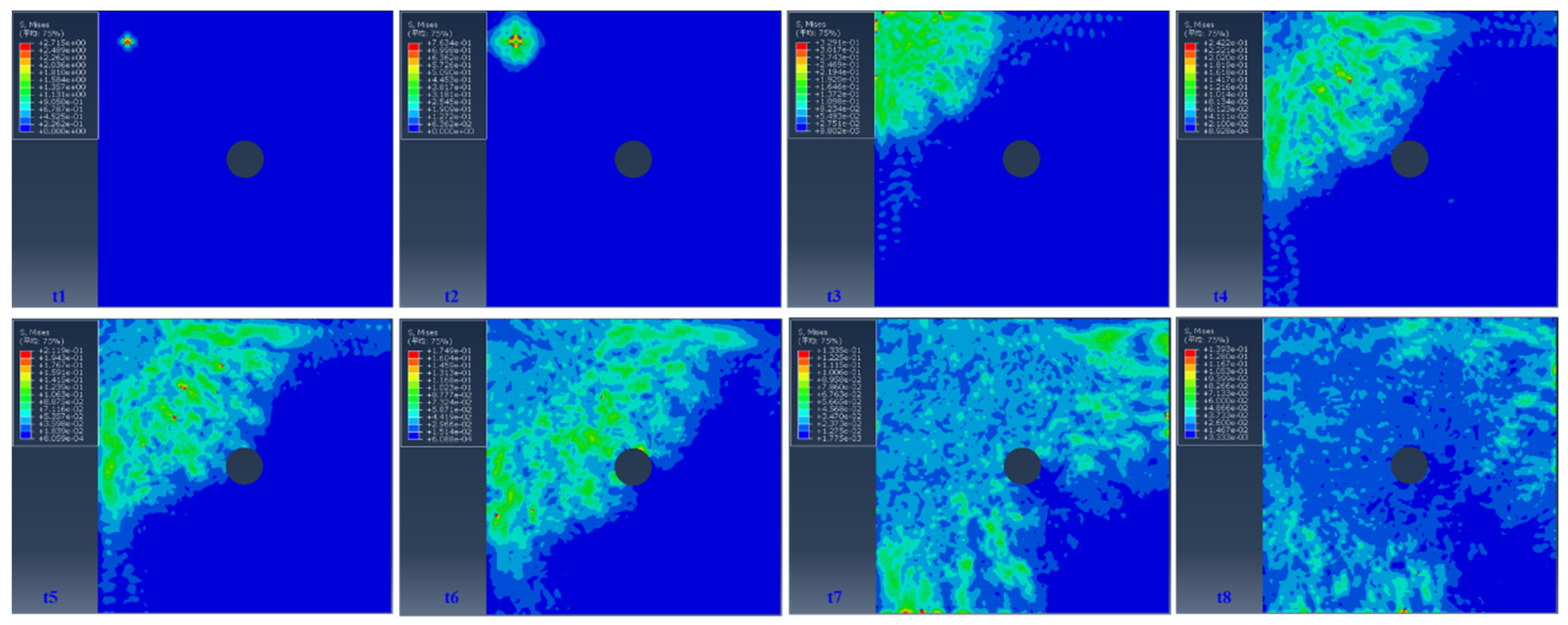
The simulation analysis of the stress wave behavior of different crack forms (circular defects with different diameters in the core, elliptical cracks, and edge cracks) in the thin plate under the impact load indicated that stress wave propagation behavior had an important influence on the damage evolution of the structure containing defects [66]. Therefore, it is of great relevance to study the dynamic response of shock stress wave propagation in metallic materials.
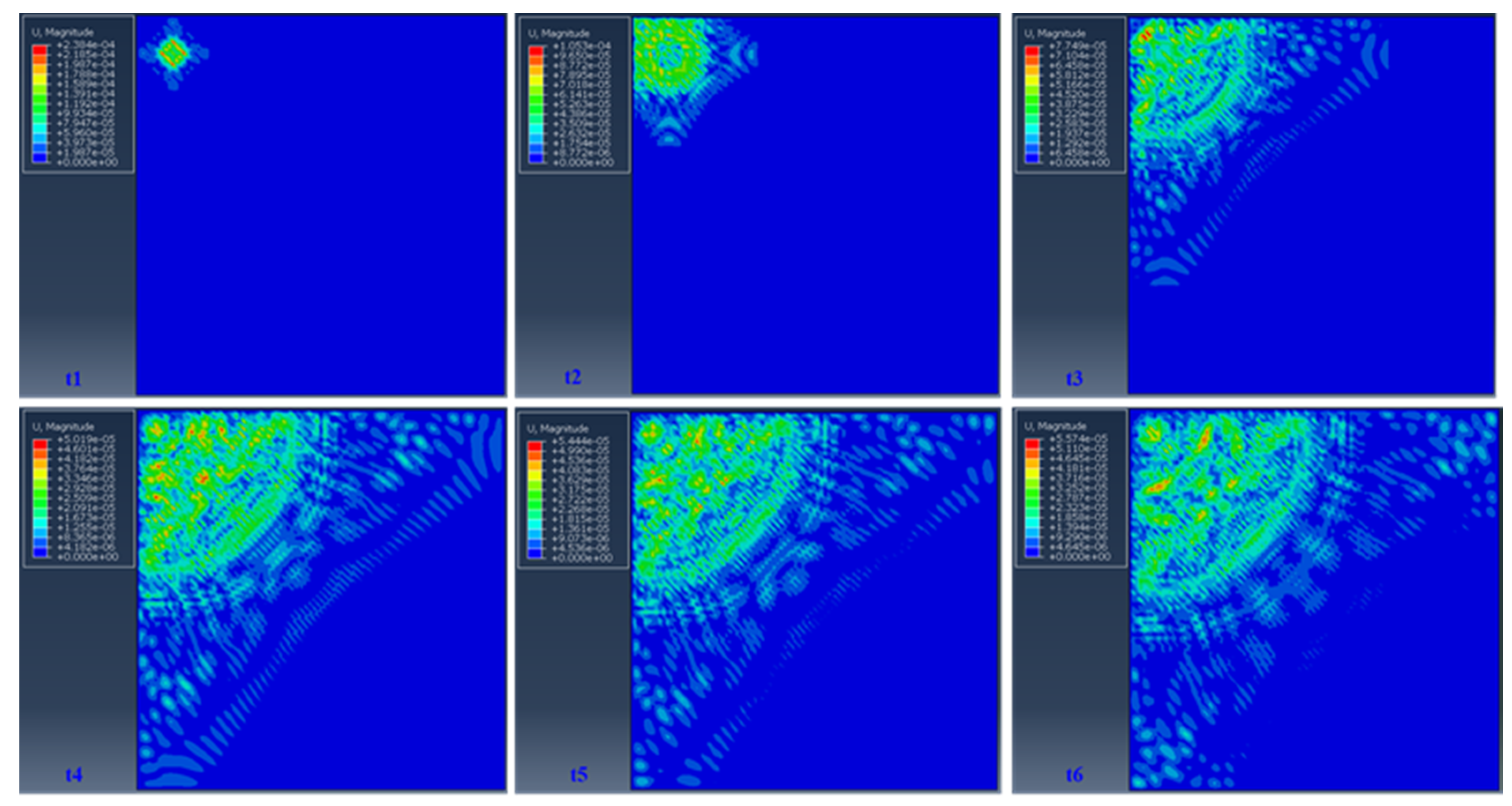
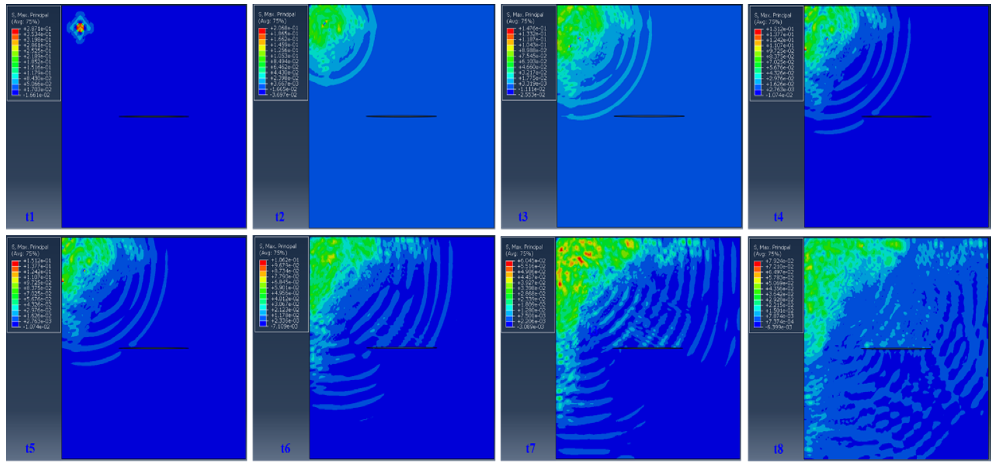
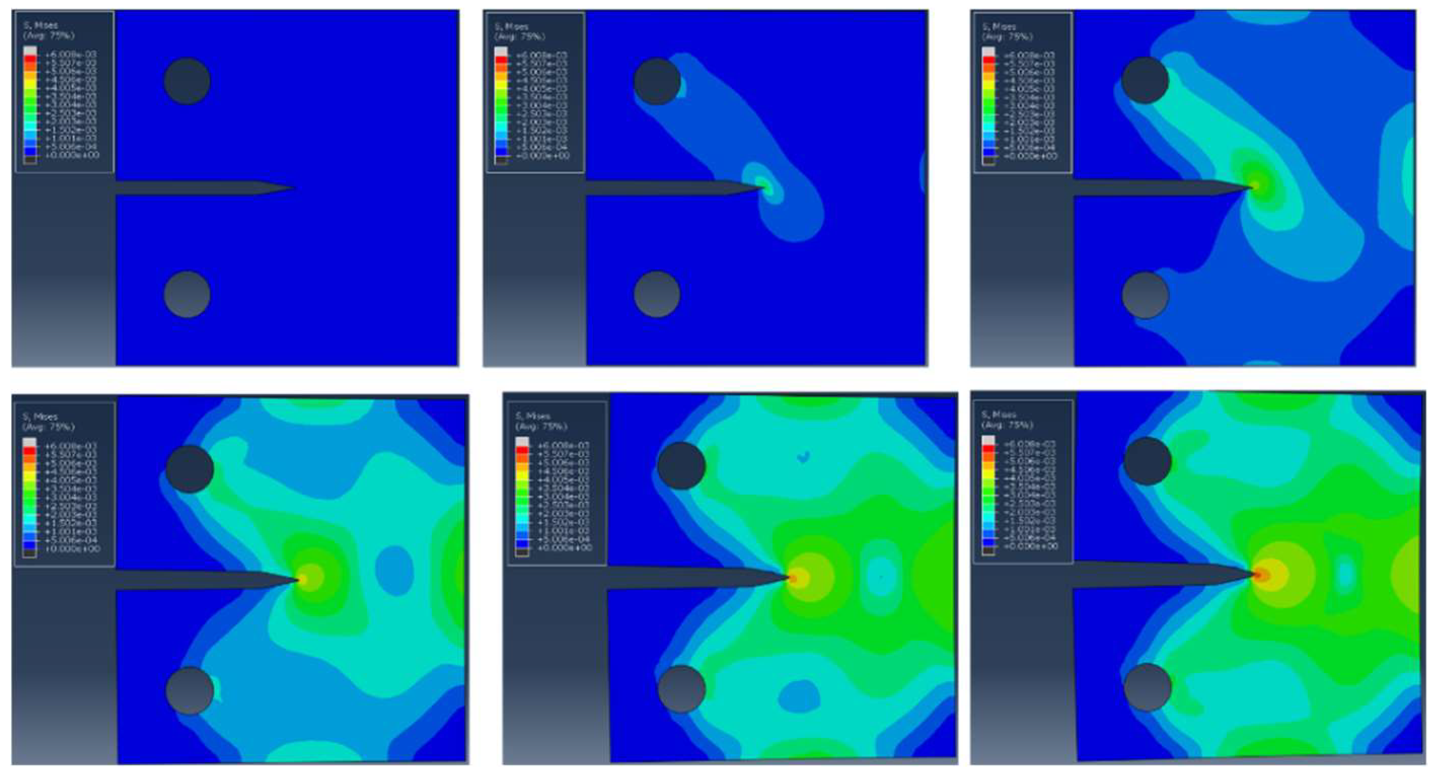
Considering the influence of different damage defects on the propagation behavior of stress waves in a flat plate, the explicit finite element method was presented in the case of the steel plate. The comparative analysis of the propagation behavior of stress waves in a two-dimensional thin plate without crack, with circular hole crack, elliptical crack, and other crack defects was considered. The geometry of the plates, and position and size of the damage, and the stress wave behavior of different defects are presented in Figure 8, Figure 9 and Figure 10.
In Figure 8, Figure 9 and Figure 10, the propagation of Lamb waves through thin aluminum plates is presented. Figure 8 presents the initial wave propagation and reflection from the position of the actuator without damage. Figure 9 and Figure 10 present the moment of wave reflection of the plate sides with edge crack and circular hole crack. All figures present the Mises stress perpendicular to the plate at the moment suitable for the visual inspection of the wave propagation through the plate. The shock stress wave propagated rapidly in the metal material. At the same time, the defect location and defect morphology had an important influence on the propagation of stress waves. The stress wave was reflected in the crack defect, and the stress wave at the tip of the crack made the tip stress and strain field more complicated. Therefore, accurate characterization of the evolutionary behavior of the stress–strain field at the tip of the crack under the action of shock stress waves is of great value for improving the design of metal components against shock.

3.3.2. Numerical Simulation of Stress Wave Propagation in the CT Sample under Impact

The dynamic fracture experiment of 2A12T4 aluminum alloy rate-independent material was carried out using a split Hopkinson pull rod device, and the corresponding fracture parameters were obtained, then the elastic–plastic fracture of 2A12T4 aluminum alloy rate-independent material under stress wave loading was analyzed by ABAQUS finite element simulation. According to the factors of crack initiation and dynamic stress balance, the mechanical response of rate-independent material under dynamic load was discussed, and the fracture parameters characterizing the material properties were obtained.
By observing the change of Mises stress field over time in the CT specimen during loading, the propagation law of stress wave in the specimen and the change process of the specimen from loading to dynamic equilibrium was obtained. The symmetrical section along the thickness direction of the specimen was selected for observation, and the results obtained are presented in Figure 11. It was observed that the stress distribution in the specimen was asymmetric at the beginning, then the stress wave began to enter the specimen and bypassed the crack tip of the specimen. After some time, the stress in the CT specimen finally reached the symmetrical distribution.
The stress values of the elements at the left and right ends of the crack tip under the impact stress wave were extracted, and the corresponding dynamic J-integral was calculated according to Equation (15) to obtain the change history of J-integral. According to the relationship (16) between J and K of linear elastic material, the stress intent was obtained, and the calculation results are presented in Figure 12.
It can be seen from Figure 12 that the K value at the crack cracking time of the sample was selected as the fracture toughness of the 2A12T4 aluminum alloy. According to the numerical simulation results, the CT sample had reached the dynamic equilibrium before fracture, and the crack cracking time of the sample was less than the maximum stress, which was consistent with the results of the sample. The research results will provide a reference for testing the dynamic fracture toughness of compact tensile specimens.

3.3.3. Numerical Simulation Analysis of Crack Growth under Impact Load

As the extended finite element method (XFEM) adds discontinuous characteristics to the displacement approximation function [67,68], an additional function item (enrichment function enrichment functions) was used to simulate the characteristics of the discontinuous surface, and the level set function was used to describe the position and geometric characteristics of the discontinuous interface so that the description of the discontinuous surface could be independent of the finite element mesh [69]. Therefore, the XFEM method did not require mesh reconstruction and could simulate the arbitrary path propagation of cracks, which was helpful for numerical simulation of impact damage [70].
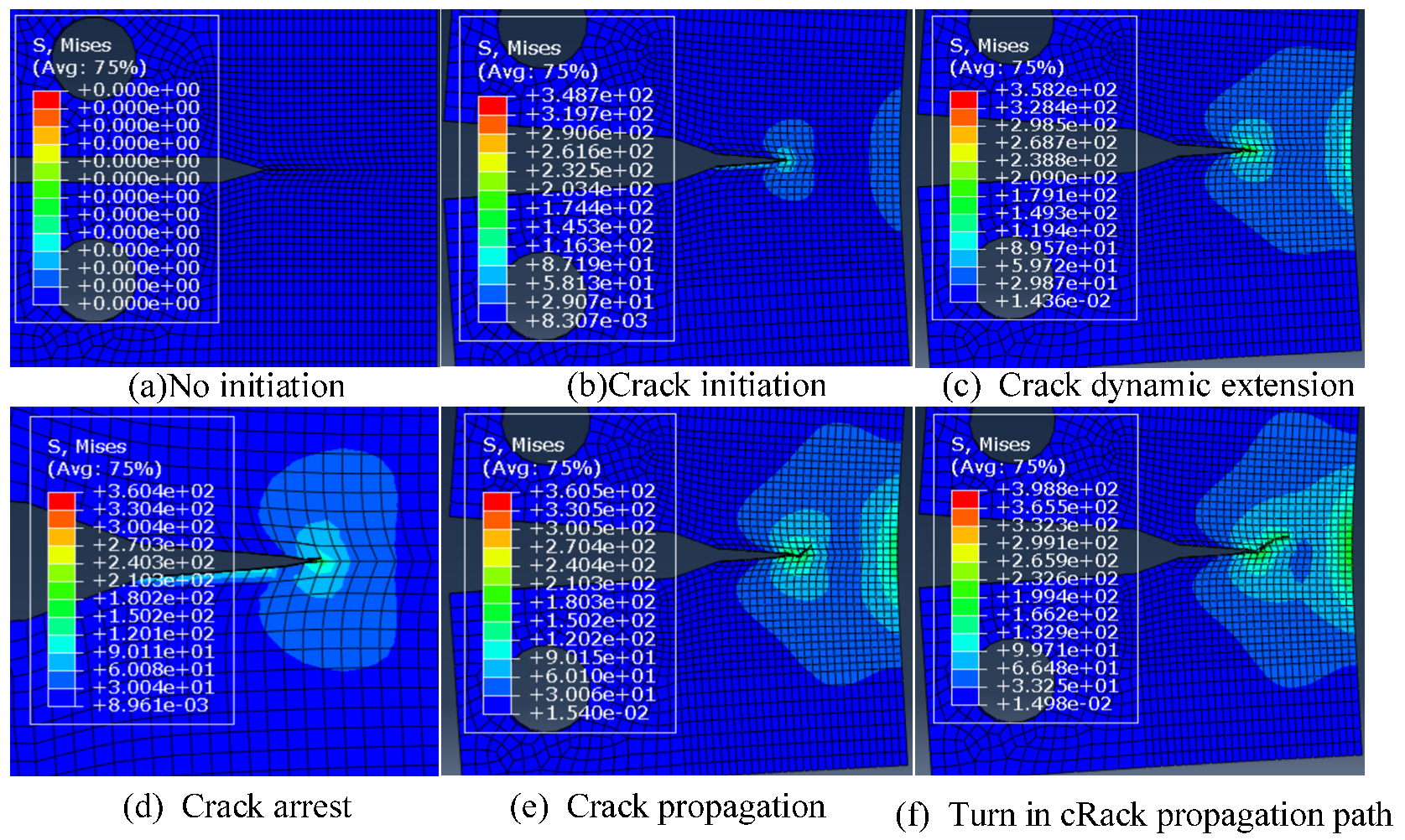
Using the extended finite element method, the numerical simulation of crack propagation under impact load of 2A12 aluminum alloy CT specimens was carried out. The simulation results are presented in Figure 13. It was observed that the sample was completely disconnected, and the crack propagated rapidly to a certain extent. The crack propagated away from the original direction and appeared in a compound fracture mode. The main reason was the shock stress wave effect and the large deformation factors of local shaping, which made the stress state of the crack tip more complicated and caused the crack propagation mode to change. The simulation results accorded with the crack growth characteristics [71].
Through the numerical simulation of the 2A12 aluminum alloy CT specimen under the impact load, coupled with the shock stress wave fluctuation model, the evolution law of the stress and strain field stimulated by the external impact of the metal material was effectively conducted. The numerical description of the crack initiation characteristics and the rapid propagation and evolutionary behavior of metal components under the action of shock stress waves lays an important foundation for the impact of deteriorating component service life and perfecting the impact fatigue life theory. Since the structure of the material determines the mechanical properties of the component, the study of the evolution of the microstructure of the metal material under the impact load will more accurately assess the impact degradation performance of the metal component, which will help with impact-resistant safety design.

4. Conclusions

Impact load has the characteristics of extremely short time, fast speed, and high strain rate. Its typical characteristics are stress fluctuation effect and strain rate effect. The study of stress wave propagation is helpful to understand the response behavior of metal materials when subjected to shock loads and to evaluate the service performance of the materials, which is of great significance. The following conclusions were obtained:
  • Based on wave theory, the evolutionary characteristics of shock stress wave behavior were explored;
  • A characterization method for the dynamic response of metallic materials under impact load was proposed, and a shock stress wave propagation model was established;
  • Through the numerical simulation of 2A12 aluminum alloy under the impact load, combined with the established wave equation, the characterization of the shock stress wave behavior was conducted;
  • At the same time, the fluctuation of the evolutionary characteristics of a shock stress wave at different defects was researched. Aimed at the dynamic response behavior of the stress and strain field at the crack tip, the dynamic fracture strength stress factor was introduced to conduct the dynamic fracture performance evaluation of the crack-damaged structure under shock waves. Numerical analysis of CT samples loaded by SHPB dynamic tie rods demonstrated that the stress wave quickly reached a state of stress equilibrium in the metal component, and the crack had begun to crack before the stress intensity factor reached the maximum.
The extended finite element method was used to numerically simulate and analyze the rapid growth of CT specimen cracks under the impact load. Due to the large local plastic deformation and impact effect under the impact load, the rapid crack propagation deviated from the original path, resulting in a compound fracture. This research work has laid an important foundation for the advancement of research on impact failure.

Author Contributions

Conceptualization, Y.L. and Y.P.; methodology, Y.L.; software, Y.L.; validation, Y.P., Y.L. and W.Z.; formal analysis, W.Z.; investigation, Y.L.; resources, W.Z.; data curation, Y.L.; writing—original draft preparation, Y.L. and Y.P.; writing—review and editing, Y.L. and Y.P.; visualization, Y.L.; supervision, Y.P.; project administration, Y.P.; funding acquisition, Y.P. All authors have read and agreed to the published version of the manuscript.

Funding

This research was funded by the National Natural Science Foundation of China grant number 52075471.

Institutional Review Board Statement

Not applicable.

Informed Consent Statement

Not applicable.

Data Availability Statement

All relevant data are obtained from the article.

Acknowledgments

The research described in this paper was financially supported by the National Natural Science Foundation of China (No. 52075471).

Conflicts of Interest

The authors declare no conflict of interest.

References

  1. Oda, J.; Murotsu, Y. (Eds.) Mechanical Design Engineering (I), Element & Design; Baifukan: Tokyo, Japan, 2000; Volume 5. [Google Scholar]
  2. Gerlach, R.; Siviour, C.R.; Petrinic, N.; Wiegand, J. Experimental characterisation and constitutive modelling of RTM-6 resin under impact loading. Polymer 2008, 49, 2728–2737. [Google Scholar] [CrossRef]
  3. Dannemann, K.A.; Chalivendra, V.B.; Song, B. Dynamic behavior of materials. Exp. Mech. 2012, 52, 117–118. [Google Scholar] [CrossRef] [Green Version]
  4. Ramesh, K.T. High Rates and Impact Experiments. In Springer Handbook of Experimental Solid Mechanics; Springer Handbooks; Sharpe, W., Ed.; Springer: Boston, MA, USA, 2008. [Google Scholar] [CrossRef]
  5. Florando, J.N.; Jiao, T.; Grunschel, S.E.; Clifton, R.J.; Lassila, D.H.; Ferranti, L.; Becker, R.C.; Minich, R.W.; Bazan, G. High Rate Plasticity Under Pressure Using a Windowed Pressure-Shear Impact Experiment; American Institute of Physics: College Park, MD, USA, 2009; pp. 723–726. [Google Scholar]
  6. Menard, K.P.; Menard, N.R. Dynamic Mechanical Analysis, 3rd ed.; CRC Press: Boca Raton, FL, USA, 2020. [Google Scholar] [CrossRef]
  7. Radović, A.; Radovanović, J. Dynamic analysis and response of systems under impact loads. In Proceedings of the 6th International Conference on Contemporary Achievements in Civil Engineering, Subotica, Serbia, 20 April 2018. [Google Scholar] [CrossRef] [Green Version]
  8. Horn, J.-T.; Krokstad, J.R.; Leira, B.J. Impact of model uncertainties on the fatigue reliability of offshore wind turbines. Mar. Struct. 2019, 64, 174–185. [Google Scholar] [CrossRef]
  9. Dodd, R.K.; Eilbeck, J.C.; Gibbon, J.D.; Morris, H.C. Soliton and Nonlinear Wave Equations; Academic Press: Cambridge, MA, USA, 1982. [Google Scholar]
  10. Mc Kean, H.P.; Vaninsky, K.L. Statistical mechanics of nonlinear wave equations. In Trends and Perspectives in Applied Mathematics; Springer: New York, NY, USA, 1994; pp. 239–264. [Google Scholar]
  11. Engelbrecht, J. Wave equations in mechanics. Est. J. Eng. 2013, 19, 273–282. [Google Scholar] [CrossRef] [Green Version]
  12. Wheeler, G.F.; Crummelt, W.P. The vibrating string contraversy. Am. J. Phys. 1987, 55, 33–37. [Google Scholar] [CrossRef]
  13. van Hoof, J.F.A.M. One and Two Dimensional Wave Propagation in Solids. WFW Reporter, 1994. Available online: https://research.tue.nl/en/studentTheses/one-and-two-dimensional-wave-propagation-in-solids (accessed on 31 October 2021).
  14. Shantharaja, M.; Sandeep, G.M. Experimental and numerical analysis of propagation of stress wave in sheet metal. Int. J. Sci. Technol. Res. 2014, 3, 40–42. [Google Scholar]
  15. Sandeep, G.M.; Avinash, D.N. A Comparative Study on Behavior of Stress Wave Propagation in Different Sheet Metals under Impact Loads. Int. J. Eng. Res. Technol. (IJERT) Etmet 2016, 4. Available online: https://www.ijert.org/a-comparative-study-on-behavior-of-stress-wave-propagation-in-different-sheet-metals-under-impact-loads (accessed on 31 October 2021).
  16. Kolsky, H.; Douch, L.S. Experimental studies in plastic wave propagation. J. Mech. Phys. Solids 1962, 10, 195–223. [Google Scholar] [CrossRef]
  17. Sadighi, M.; Pärnänen, T.; Alderliesten, R.; Sayeaftabi, M.; Benedictus, R. Experimental and numerical investigation of metal type and thickness effects on the impact resistance of fiber metal laminates. Appl. Compos. Mater. 2012, 19, 545–559. [Google Scholar] [CrossRef]
  18. Seife, C. Seventeen Equations That Changed the World; Times Higher Education: London, UK, 2012. [Google Scholar]
  19. Wang, L. Tide Wave Basics [M], 2nd ed.; National Defense Industry Press: Beijing, China, 2005. [Google Scholar] [CrossRef]
  20. Friedrichs, K.O. Asymptotic phenomena in mathematical physics. Bull. Am. Math. Soc. 1955, 61, 485–504. [Google Scholar] [CrossRef] [Green Version]
  21. French, A.P. Vibrations and Waves, 1st ed.; CRC Press: Boca Raton, FL, USA, 1971. [Google Scholar] [CrossRef]
  22. Leppänen, J. Splitterverkan; (Report: MSB345); Myndigheten för Samhällskydd Och beredskap: Karlstad, Sweden, 2012. [Google Scholar]
  23. Tell, F.; Svensson, T. Stress Wave Propagation between-Different Materials. Master’s Thesis, Chalmers University of Technology, Gothenburg, Sweden, May 2015. [Google Scholar]
  24. Khodaei, Z.S.; Aliabadi, M.H. Assessment of delay-and-sum algorithms for damage detection in aluminium and composite plates. Smart Mater. Struct. 2014, 23, 075007. [Google Scholar] [CrossRef]
  25. Dennis, G. Physics of Shock and Impact; IOP Publishing: Bristol, UK, 2017. [Google Scholar] [CrossRef]
  26. Meyers, M.A.; Thadhani, N.N.; Yu, L.H. Shock waves for industrial applications. Noyes: Hammonton, NJ, USA, 1988; p. 265. [Google Scholar]
  27. Ha, Y.D.; Bobaru, F. Studies of dynamic crack propagation and crack branching with peridynamics. Int. J. Fract. 2010, 162, 229–244. [Google Scholar] [CrossRef] [Green Version]
  28. Gao, L.; Liu, K.; Ying, L. A meshless method for stress-wave propagation in anisotropic and cracked media. Int. J. Eng. Sci. 2007, 45, 601–616. [Google Scholar] [CrossRef]
  29. Tian, Z.; Huo, L.; Gao, W.; Li, H.; Song, G. Modeling of the attenuation of stress waves in concrete based on the rayleigh damping model using time-reversal and put transducers. Smart Mater. Struct. 2014, 23, 075007. [Google Scholar]
  30. Liu, K.; Gao, L.; Tanimura, S. Application of discrete element method in impact problems. JSME Int. J. 2005, 47, 138–145. [Google Scholar] [CrossRef] [Green Version]
  31. Azari, H.; Nazarian, S.; Yuan, D. Assessing the sensitivity of impact echo and ultrasonic surface waves methods for nondestructive evaluation of concrete structures. Constr. Build. Mater. 2014, 71, 384–391. [Google Scholar] [CrossRef]
  32. Dziedziech, K.; Pieczonka, L.; Kijanka, P.; Staszewski, W.J. Enhanced nonlinear crack-wave interactions for structural damage detection based on guided ultrasonic waves. Struct. Control Health Monit. 2016, 23, 1108–1120. [Google Scholar] [CrossRef]
  33. Carino, N.J. Stress Wave Propagation Methods; CRC Press: Boca Raton, FL, USA, 2003. [Google Scholar]
  34. Owen, D.M.; Zhuang, S.; Rosakis, A.J.; Ravichandran, G. Experimental determination of dynamic crack initiation and propagation fracture toughness in thin aluminum sheets. Int. J. Fract. 1998, 90, 153–174. [Google Scholar] [CrossRef]
  35. Rittel, D.; Maigre, H. An investigation of dynamic crack initiation in Emma. Mech. Mater. 1996, 23, 229–239. [Google Scholar] [CrossRef]
  36. Yue, Z.W.; Yang, R.S.; Guo, D.M.; Cao, H.; Dong, J.C. Dynamic analysis of crack propagation in media containing flaws under the explosive stress wave. Rock Soil Mech. 2009, 30, 949–954. [Google Scholar]
  37. Cui, X.; Fan, Y.; Wei, J.I.; Chen, J. Progress in the research of dynamic fracture toughness based on hopkinson Hopkinson bar technique. Ordnance Mater. Sci. Eng. 2010, 32, 118–122. [Google Scholar]
  38. Li, H.; Wong, L. Influence of flaw inclination angle and loading condition on crack initiation and propagation. Int. J. Solids Struct. 2012, 49, 2482–2499. [Google Scholar] [CrossRef] [Green Version]
  39. Truesdell, C.; Noll, W. The non-linear field theories of mechanics. In The Non-Linear FIELD Theories of Mechanics; Springer: Berlin/Heidelberg, Germany, 2004; pp. 1–579. [Google Scholar]
  40. Engelbrecht, J. Nonlinear Wave Dynamics: Complexity and Simplicity; Springer Science & Business Media: Berlin, Germany, 2013; Volume 17. [Google Scholar]
  41. Meyers, M.A.; Murr, L.E. Propagation of Stress Waves in Metals; Springer: Amsterdam, The Netherlands, 1983. [Google Scholar]
  42. Noël, J.P.; Renson, L.; Grappasonni, C.; Kerschen, G. Dynamic Behavior of Materials; Springer: New York, NY, USA, 2016. [Google Scholar]
  43. Bolt, B.A. Seismic input motions for nonlinear structural analysis. ISET J. Earthq. Technol. 2004, 41, 223–232. [Google Scholar]
  44. Barkan, D.D. Dynamics of Bases and Foundations; McGraw-Hill: New York, NY, USA, 1948; Volume 1962, 434p. [Google Scholar]
  45. Sansalone, M.; Carino, N.J.; Hsu, N.N. A finite element study of transient wave propagation in plates. J. Res. Natl. Bur. Stand. 1987, 92, 267–278. [Google Scholar] [CrossRef]
  46. Chen, F.; Shield, R.T. Conservation laws in elasticity of the J-integral type. Z. Angew. Math. Phys. 1977, 28, 1–22. [Google Scholar] [CrossRef]
  47. Schwalbe, K.H. Comparison of several fatigue crack propagation laws with experimental results. Eng. Fract. Mech. 1974, 6, 325–341. [Google Scholar] [CrossRef]
  48. Li, X.; Lu, X.; Li, M.; Hao, J.; Xu, Y. Numerical Study on Evaluating the Concrete-Bedrock Interface Condition for Hydraulic Tunnel Linings Using the SASW Method. Appl. Sci. 2018, 8, 2428. [Google Scholar] [CrossRef] [Green Version]
  49. Zhao, H.; Gary, G. On the use of SHPB techniques to determine the dynamic behavior of materials in the range of small strains. Int. J. Solids Struct. 1996, 33, 3363–3375. [Google Scholar] [CrossRef]
  50. Zhang, W.; Gang, W.; Xiao, X. The constitutive relationship and failure model of 2A12 aluminum alloy. Acta Armamentarii 2013, 34, 276–282. [Google Scholar]
  51. Ramulu, P.J. Aluminum Alloys Behavior during Forming. Aluminium Alloys and Composites; IntechOpen: Adama, Ethiopia, 2019. [Google Scholar]
  52. Liu, J.; Shao, X.J.; Liu, Y.S.; Yue, Z.F. Effect of cold expansion on fatigue performance of open holes. Mater. Sci. Eng. A 2008, 477, 271–276. [Google Scholar] [CrossRef]
  53. ABAQUS/Standard User’s Manual; Version 6.1; HKS Inc.: Providence, RI, USA, 2000.
  54. Chen, G. A method of incident pulse shaping for SHPB. WIT Trans. Built Environ. 2014, 141, 181–189. [Google Scholar]
  55. Kishimoto, K.; Aoki, S.; Sakata, M. Simple formula for dynamic stress intensity factor of pre-cracked Charpy specimen. Eng. Fract. Mech. 1980, 13, 501–508. [Google Scholar] [CrossRef]
  56. Li, C. Experimental Study on the Constitutive Relationship of 2A12 Aluminum Alloy; Harbin Institute of Technology: Harbin, China, 2006. [Google Scholar]
  57. Kishimoto, K.; Aoki, S.; Sakata, M. On the path independent integral-j. Eng. Fract. Mech. 1980, 13, 841–850. [Google Scholar] [CrossRef]
  58. Nishioka, T. Computational dynamic fracture mechanics. Int. J. Fract. 1997, 86, 127–159. [Google Scholar] [CrossRef]
  59. Rice, J.R. A Path Independent Integral and the Approximate Analysis of Strain Concentration by Notches and Cracks. J. Appl. Mech. 1968, 35, 379–386. [Google Scholar] [CrossRef] [Green Version]
  60. Zhou, H.-L. The derivation of the relationship between J integral and KI in view of the plane stress state. J. Chongqing Jiaotong Univ. 2006, 02, 35–37. [Google Scholar]
  61. Sun, H.; Zhu, J. Monitoring early age properties of cementitious material using ultrasonic guided waves in embedded rebar. J. Nondestruct. Eval. 2017, 36, 5. [Google Scholar] [CrossRef] [Green Version]
  62. Moreno-Garcia, P.; Lopes, H.; Araujo, d.S.J.V. Application of higher-order finite differences to damage localization in laminated composite plates. Compos. Struct. 2016, 156, 385–392. [Google Scholar] [CrossRef]
  63. Moll, J.; Golub, M.V.; Glushkov, E.; Glushkova, N.; Fritzen, C.P. Non-axisymmetric lamb wave excitation by piezoelectric wafer active sensors. Sens. Actuators A Phys. 2012, 174, 173–180. [Google Scholar] [CrossRef]
  64. Peng, H.; Meng, G.; Li, F. Modeling of wave propagation in plate structures using three-dimensional spectral element method for damage detection. J. Sound Vib. 2009, 320, 942–954. [Google Scholar] [CrossRef]
  65. Ham, S.; Bathe, K.J. A finite element method enriched for wave propagation problems. Comput. Struct. 2012, 94–95, 1–12. [Google Scholar] [CrossRef] [Green Version]
  66. Stojić, D.; Nestorović, T.; Marković, N.; Marjanović, M. Experimental and numerical research on damage localization in plate-like concrete structures using hybrid approach. Struct. Control Health Monit. 2018, 25, e2214. [Google Scholar] [CrossRef]
  67. Li, H.; Li, J.; Huang, Y. A review of the extended finite element method on macrocrack and microcrack growth simulations. Theor. Appl. Fract. Mech. 2018, 97, 236–249. [Google Scholar] [CrossRef]
  68. Prabel, B.; Combescure, A.; Gravouil, A.; Marie, S. Level set X-FEM non-matching meshes: Application to dynamic crack propagation in elastic–plastic media. Int. J. Numer. Methods Eng. 2007, 69, 1553–1569. [Google Scholar] [CrossRef] [Green Version]
  69. Remmers, J.J.; de Borst, R.; Needleman, A. The simulation of dynamic crack propagation using the cohesive segments method. Opt. Commun. 2008, 56, 70–92. [Google Scholar] [CrossRef]
  70. Guo, L.; Zhong, W.; Chen, Z.; Luo, J. Numerical simulation of dynamic crack propagation process of magnesium-aluminum alloy under impact load. Explos. Shock. 2016, 36, 7. [Google Scholar]
  71. Wu, L.; Zhang, L.X.; Guo, Y.K. A review of the extended finite element for fracture analysis of structures. In Applied Mechanics and Materials; Trans Tech Publications Ltd.: Wollerau, Switzerland, 2014; Volume 444. [Google Scholar]
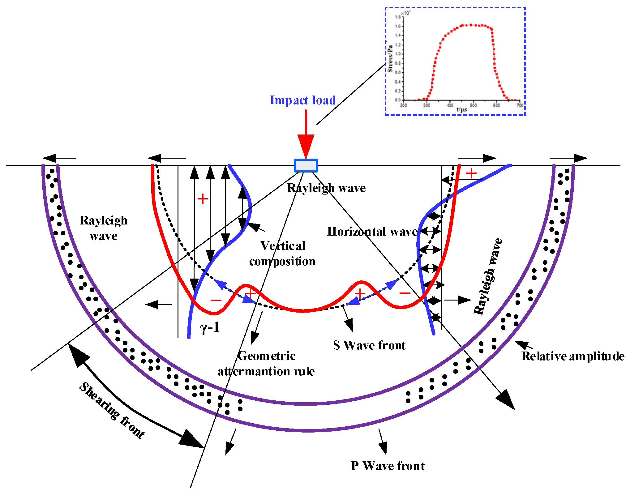
Figure 1. Schematic elastic wave propagation generated by impact excitation.
Metals 11 01920 g001
Figure 2. Stress diagram of equilibrium microelement.
Metals 11 01920 g002
Figure 3. Coordinate system at the crack tip under transient loading.
Metals 11 01920 g003
Figure 4. A schematic diagram of the tension SHPB test.
Metals 11 01920 g004
Figure 5. Two-dimensional section model of a compact tensile specimen.
Metals 11 01920 g005
Figure 6. Three-dimensional finite element model of a compact tensile specimen.
Metals 11 01920 g006
Figure 7. Stress load curve under impact: (a) curves of the incident wave, reflected wave, and transmitted wave; (b) curve of stress waves.
Metals 11 01920 g007
Figure 8. Simulation of stress wave propagation in the thin plate under impact load.
Metals 11 01920 g008
Figure 9. Simulation of stress wave propagation in a thin plate with a long core crack.
Metals 11 01920 g009
Figure 10. Simulation analysis of stress wave propagation in a thin plate with circular defects.
Metals 11 01920 g010
Figure 11. Stress program of stress wave at crack at different times.
Metals 11 01920 g011
Figure 12. The curves of JI(t) and KI(t).
Metals 11 01920 g012
Figure 13. Simulation of impact crack growth using XFEM method.
Metals 11 01920 g013
Table 1. 2A12 aluminum alloy mechanical model parameters.
Johnson-Cook ModelA(MPa)B(MPa)nCm
σ y = [ A + B ε n ] ( 1 + C l n ε * ˙ ) ( 1 T * m ) 370.41798.70.733150.01281.5282
Table 2. Quasi-static mechanical material properties.
2A12T4Value
Density (ρ) [kg/m3]2800
Modulus elasticity (E) [GPa]68.3
Poisson ratio (ν)0.33
Yield stress (MPa)330
Failure strain0.12
Publisher’s Note: MDPI stays neutral with regard to jurisdictional claims in published maps and institutional affiliations.