Review

Strengthening Mechanisms in Carbon Nanotubes Reinforced Metal Matrix Composites: A Review

1
DEMM, Department of Metallurgical and Materials Engineering, University of Porto, R. Dr. Roberto Frias, 4200-465 Porto, Portugal
2
LAETA/INEGI, Institute of Science and Innovation in Mechanical and Industrial Engineering, R. Dr. Roberto Frias, 4200-465 Porto, Portugal
*
Author to whom correspondence should be addressed.
Metals 2021, 11(10), 1613; https://doi.org/10.3390/met11101613
Submission received: 3 September 2021 / Revised: 4 October 2021 / Accepted: 8 October 2021 / Published: 11 October 2021

Abstract

:
Carbon nanotubes (CNTs)-reinforced metal matrix composites are very attractive advanced nanocomposites due to their potential unusual combination of excellent properties. These nanocomposites can be produced by several techniques, the most reported being powder metallurgy, electrochemical routes, and stir or ultrasonic casting. However, the final mechanical properties are often lower than expected. This can be attributed to a lack of understanding concerning the strengthening mechanisms that act to improve the mechanical properties of the metal matrix via the presence of the CNTs. The dispersion of the CNTs is the main challenge in the production of the nanocomposites, and is independent of the production technique used. This review describes the strengthening mechanism that act in CNT-reinforced metal matrix nanocomposites, such as the load transfer, grain refinement or texture strengthening, second phase, and strain hardening. However, other mechanisms can occur, such as solid solution strengthening, and these depend on the metal matrix used to produce the nanocomposites. Different metallic matrices and different production techniques are described to evaluate their influence on the reinforcement of these nanocomposites.

1. Introduction

In the last 20 years, an increase in studies on the production and development of metallic matrix nanocomposites reinforced with CNTs has been observed [1,2,3,4,5,6,7,8,9,10,11,12,13,14]. This interest is due to the enormous potential of these nanocomposites to respond to the high challenges imposed by the development of novel materials and components [15,16,17,18,19,20,21,22,23,24,25,26,27,28,29,30,31,32,33,34,35]. There is an increasing interest in developing new lightweight materials with attractive properties in order to establish a more sustainable industry [36,37,38,39,40,41,42,43,44,45,46,47].
It is known that due to the attractive properties of CNTs, such as high mechanical resistance, high electrical and thermal conductivities, this material has enormous potential to be used as a reinforcement material. The combination of metallic materials (pure or alloys) and CNTs allows for obtaining nanocomposites with high potential for a range of applications, such as in the aerospace, automotive, transportation, electronics, nanotechnology, and energy industries [48,49,50,51,52,53,54,55,56,57].
Since the first work was published on Al/CNTs composites [1], an exponential increase has been observed in works published on the production and characterization of metal matrix/CNT composites (MM/CNT). The main pure materials used as a matrix are Al [1,2,3,4,5,6,7,8,9,10,11,12,13,14], Cu [15,16,17,18,19,20,21,22,23,24], Ni [25,26,27,28,29,30,31,32,33,34,35], Mg [36,37] and Ti [38,39,40,41]. Some works also use Al, Mg, and Ni alloys in matrices reinforced by CNTs [46,47,58,59,60,61]. Figure 1 shows the evolution of the number of published papers on pure metal matrices reinforced by CNTs.
These nanocomposites can be produced via various manufacturing processes. Those with the greatest potential are (i) powder metallurgy, (ii) electrochemical techniques, (iii) casting associated with stirring or ultrasonic mixing, (iv) thermal spraying, and (v) other novel techniques. Figure 2 shows the main production techniques used to obtain MM/CNT composites.
Regardless of the technique used, the main challenge is obtaining composites with a uniform dispersion of CNTs and strong interface bonding, and which avoids a chemical reaction between the CNTs and the matrix [56,62,63,64].
Powder metallurgy route is the most reported technique to produce CNT-reinforced metal matrix composites. This is a simple, flexible, and near-net-shape process. The success of the CNTs’ dispersion will depend on the dispersion and mixture techniques performed prior to processing [55,62,63,64]. Dispersion techniques can be applied before the pressing and sintering process. The pressing and sintering processes can be performed in different routes, which can be divided into (1) conventional sintering, (2) hot pressing, (3) spark plasma sintering, and (4) deformation processing after the sintering. Conventional sintering is a very attractive technique. It was the first approach described for MM/CNT production but is characterized by the production of composites with poor densities [62,63,64]. The other processes allow for improving the density of the composites and even the dispersion of the reinforced materials, such as deformation processing after sintering.
Electrochemical routes can be used to produce MM/CNT coatings or thin films. This process is very effective in producing nanocomposites. However, it is limited to freestanding or bulk samples and is typically only used with Cu and Ni metal matrices [62,63,64].
Casting is an attractive processing technique since it is economical and straightforward when used to produce nanocomposites in large quantities. However, due to the problem of the wettability of the CNTs, the metal matrices promote the formation of nanocomposites with a poor dispersion of CNTs. Using stir-assistance, introducing the reinforcement into a liquid–metal matrix seems to be an excellent approach to obtain a more uniform dispersion of the CNTs [55,62,63,64]. Novel techniques have been developed to overcome the challenges of the conventional methods employed in the production of MM/CNTs. These techniques use sputtering, sandwich processing, nanoscale dispersion, or laser deposition to obtain a good dispersion of the CNTs throughout the metal matrix composites without damaging them [62,63,64].
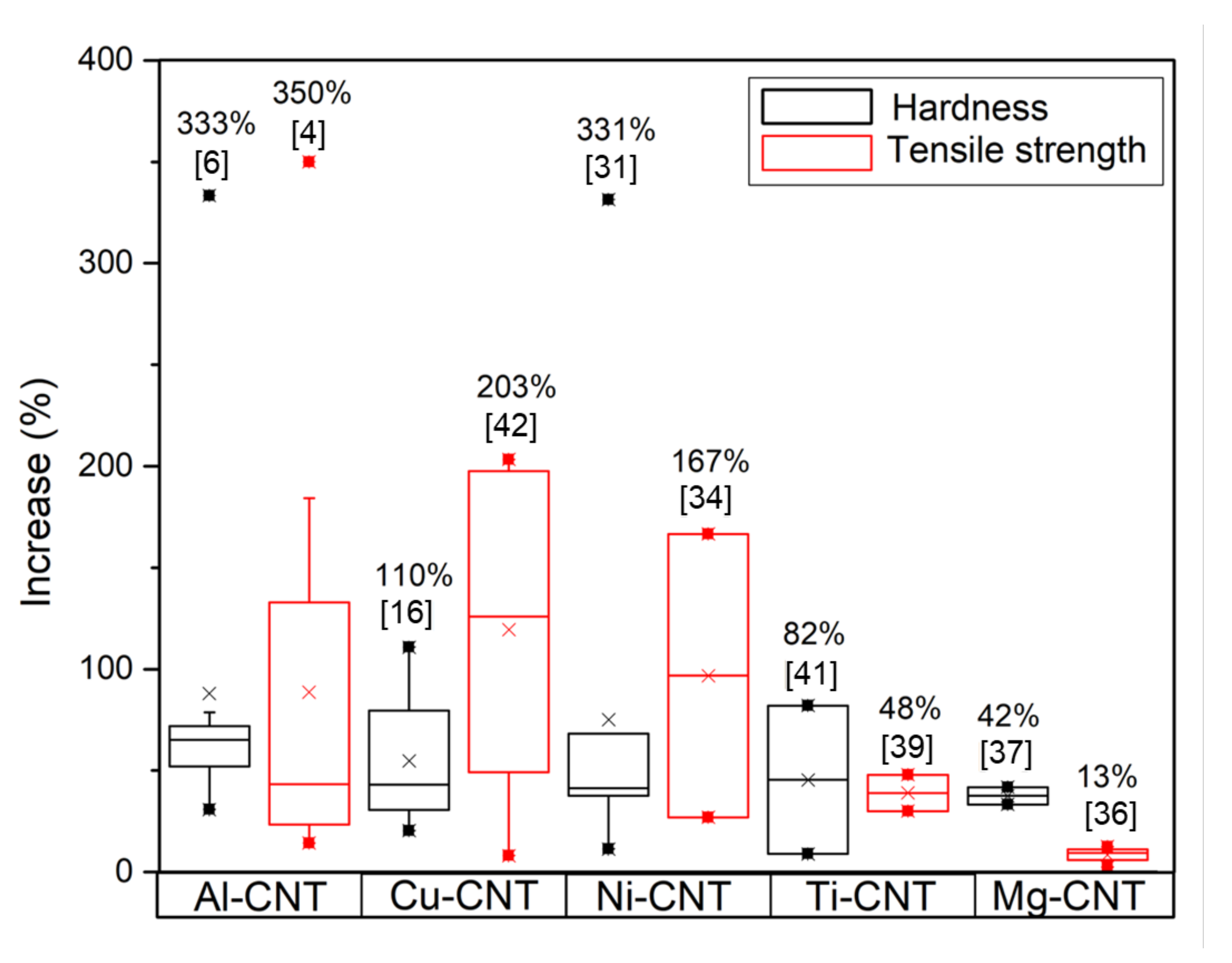
In recent years, a considerable number of publications [44,45,46,47,48,49,50,51,52,53,54,55,56,57,58,59,60,61] have shown that the achieved increases in the mechanical properties of MM/CNT composites are significantly less than their potential, considering the extraordinarily high resistance of carbon nanotubes (up to 100 GPa). This observation is even more significant in composites produced with CNTs at levels higher than >2 vol.%. The agglomeration of CNTs decreases the strengthening effect of this reinforcement when it is introduced into metallic matrices. This effect is critical when using greater amounts of CNTs, and the nanocomposites cause deterioration of mechanical properties. Controlling the metal matrix’s microstructure is also essential to obtaining the expected improvement in the mechanical properties. Figure 3 shows the improvements obtained in different metal matrix composites reinforced with CNTs produced by other processing techniques and using different approaches to CNT dispersion.
Different approaches have been investigated to improve the dispersion of CNTs into metallic matrices. For instance, in the nanocomposites produced by powder metallurgy, ultrasonication and ball milling with or without such pre-treatments as functionalization are the two main techniques reported. In contrast, for casting, pre-treatment and stir- or ultrasonic mixing are the approaches that promote the best dispersion of the reinforcement. Some authors have reported that post-processing techniques such as rolling and hot extrusion can improve the dispersion and the density of the nanocomposites. However, the damage that the CNTs can suffer during these techniques can be key to the success of the production of the MM/CNT. Some of the dispersion/mixture techniques induce structural damage that strongly influences the properties of the CNTs.
The chemical reaction between the CNTs and the metallic matrices is also an essential factor that needs to be evaluated during the production of the MM/CNT. On the one hand, the chemical reaction may result in the formation of a second phase with less attractive characteristics than those of the CNTs; on the other hand, the reaction may be beneficial if the particles fraction is not significant. The presence of a second phase may affect the strengthening mechanism directly when it interacts with the dislocation movement, and indirectly when it promotes a stronger interface between the matrix and the CNT.
The reinforcement effect occurs due to several strengthening mechanisms that act simultaneously, and therefore, its identification presents several difficulties. For this reason, the potential of these nanocomposites can be compromised by the lack of scientific knowledge regarding the identification of the individual strengthening mechanisms and the effect of the presence of CNTs in the microstructure, which determines the MM/CNT’s properties.
This review provides a broad description of the strengthening mechanisms identified in the metal matrix nanocomposites reinforced by CNTs.

2. Strengthening Mechanisms

Several strengthening mechanisms can act simultaneously to improve the metal matrix properties due to the introduction of CNTs. The different mechanisms will contribute to the improvement of the mechanical properties [61,62,63,64,65,66,67,68,69,70,71,72,73,74,75,76,77]. The most widely reported in CNT-reinforced metal matrix composites are: (1) load transfer; (2) grain refinement or texture strengthening; (3) second phase hardening and (4) strain hardening. However, other mechanisms such as solid solution strengthening can occur, and these depend on the metal matrix used to produce the nanocomposites. The following sections will describe each of the mechanisms and present works on MM/CNTs wherein these mechanisms have been identified.

2.1. Load Transfer Mechanism

Load transfer is the most commonly reported strengthening mechanism for metal matrix nanocomposites reinforced by CNTs [61,66,67,68,69,70,71,72,73,74,75,76,77]. This is achieved by transferring the load from the matrix to the CNTs through their interface. The strengthening of the nanocomposite occurs since the CNTs exhibit higher strength and hardness than the metal matrix. The load transfer depends on the bonding strength between the reinforcement and the matrix, and the CNTs’ volume fraction and aspect ratio.
The CNT/matrix interface is a significant factor in the strengthening of the nanocomposites. A strong interface between the CNT and the matrix is necessary for effective load transfer [66].
Kelly and Tyson’s modified shear lag model [78] is the most typically used to characterize the load transfer mechanism. Based on this model, the yield strength of the composite, σc, can be obtained by:
σ C = σ M V C N T S e f f + 2 2 + 1 V C N T
where VCNT is the volume fraction of the CNTs, σM is the matrix yield strength and Seff is the effective aspect ratio of the CNTs.
Observations of surface fractures in the nanocomposites are one possible way to identify the load transfer mechanism.
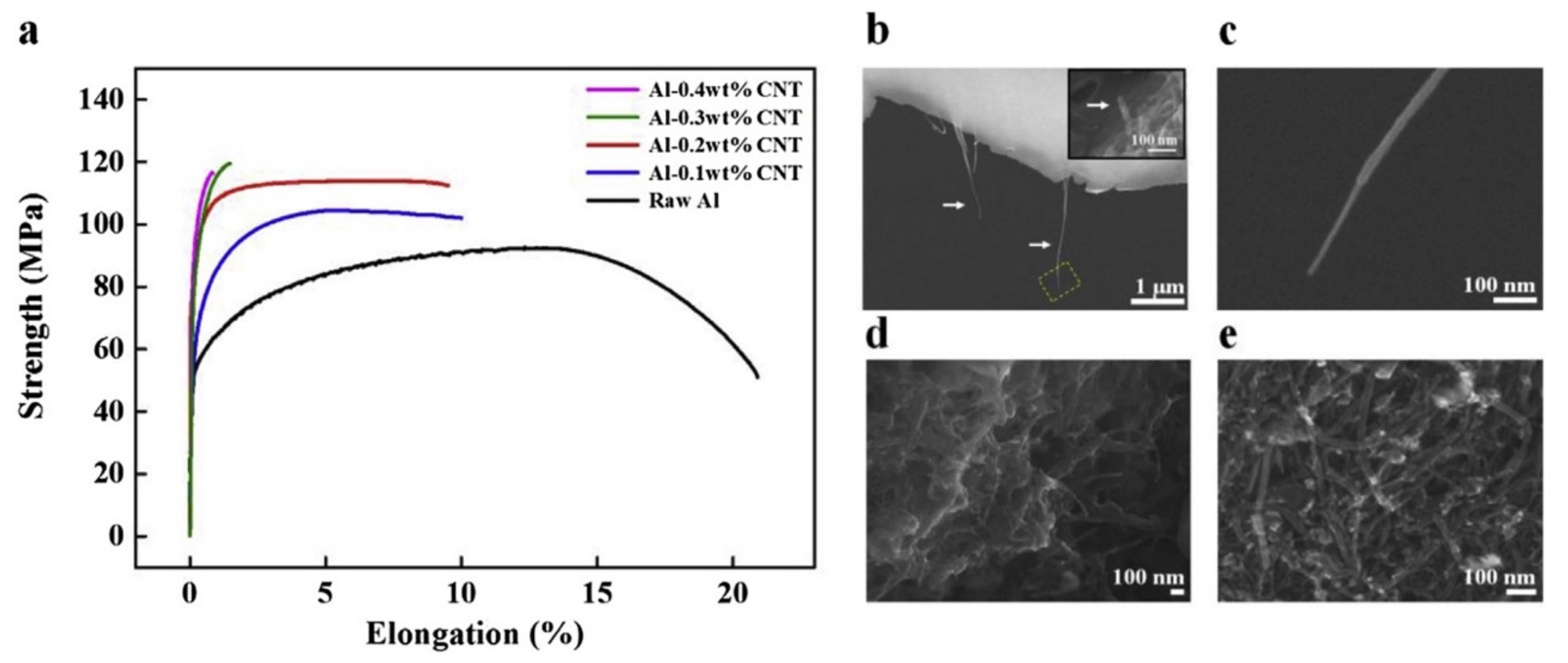
Park et al. [68] investigated the strengthening mechanism of carbon nanotube-reinforced aluminum composites. The yield strength of the nanocomposites was improved by 60% in those produced with 0.2 wt.% of CNTs. Different strengthening mechanisms were identified, such as load transfer, the increasing of the dislocation density, and the Orowan mechanism. The load transfer mechanism was found to be dominant. Figure 4 shows the tensile curves and fracture surfaces of the nanocomposites, showing the CNT was fractured and pulled out.
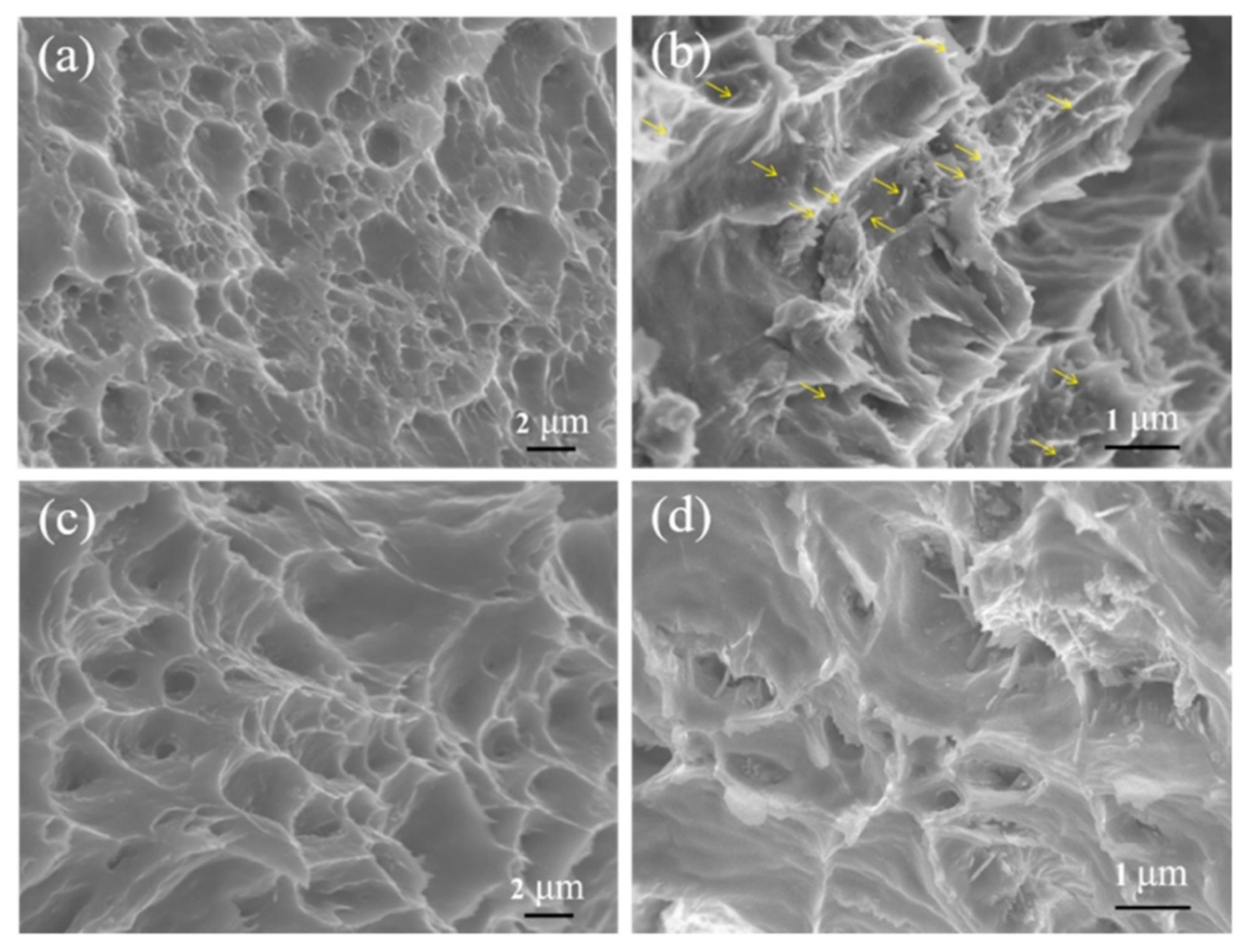
Xie et al. [72] produced Al/CNT composites with a large and small aspect ratio of CNTs by conventional sintering followed by hot extrusion. The uniform dispersion of the CNTs in the Al matrix was observed for 1.0 wt.% CNTs. The tensile curves prove the reinforcement effect of the introduction of the CNTs on the Al matrix. The surface fracture observations reveal that CNTs could be observed after the tensile tests, indicating that one possible strengthening mechanism is load transfer. Figure 5 shows the scanning electron microscopy (SEM) images of the fracture surfaces of the nanocomposites produced with large and small aspect ratios of CNTs. The observation of these images reveals holes, and some CNTs with a free end can be found in dimples, suggesting that they may be fractured.
The observation of the fracture surfaces of the tensile specimens of the MM/CNT to assess the strengthening mechanism in action has also been performed by other authors and for different matrices. For instance, Hwang et al. [75] and Nguyen et al. [76] observed the surface fractures of the Ni/CNT in order to assess the presence of CNTs after the tensile testing of the composites, and Kondoh et al. [38] identified the load transfer mechanism for pure Ti/CNT composites produced by powder metallurgy.
However, observing CNT failure via in situ tensile tests is the best approach to evaluating this strengthening mechanism in the nanocomposites [69,79,80,81].
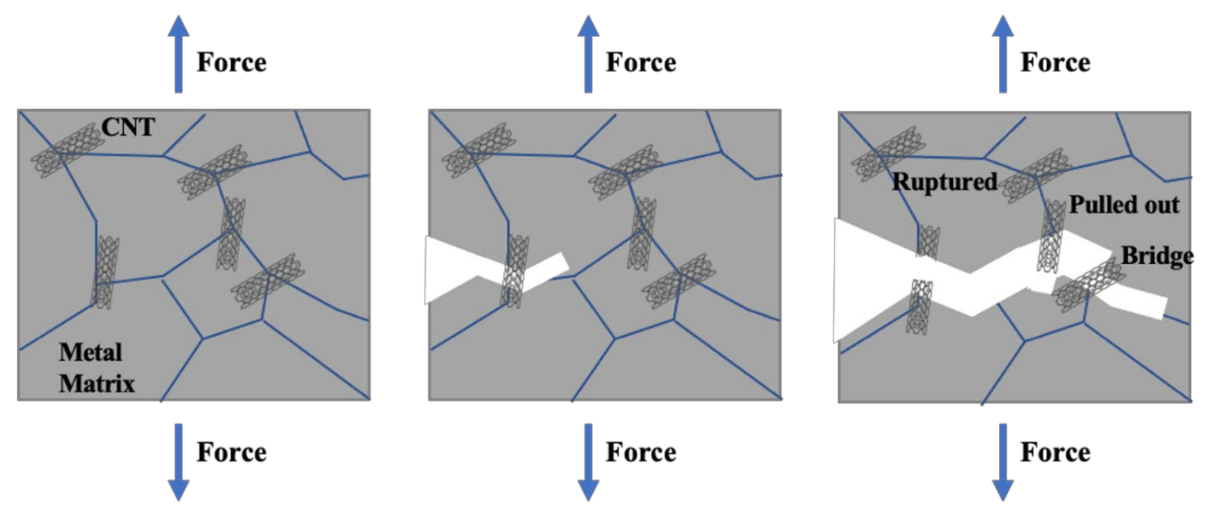
In situ tests revealed that the CNTs acted as a bridge and restrained the growth of the crack during the tensile tests. As the tensile displacement increased, when the interface bonding was strong, the CNT started to fracture, but when the interface was weak, the CNT was pulled out. Figure 6 shows a schematic of possible CNT behavior during the tensile testing of the MM/CNT. As the cracks expanded towards the CNT, the CNT acted as a bridge and restrained the growth of the crack. As the tensile displacement increased, the cracks approached the CNTs, and if the interface of the CNT/matrix was strong, then CNT fracturing occurred. On the contrary, when the interface of CNT/matrix was poor, CNT was pulled out.
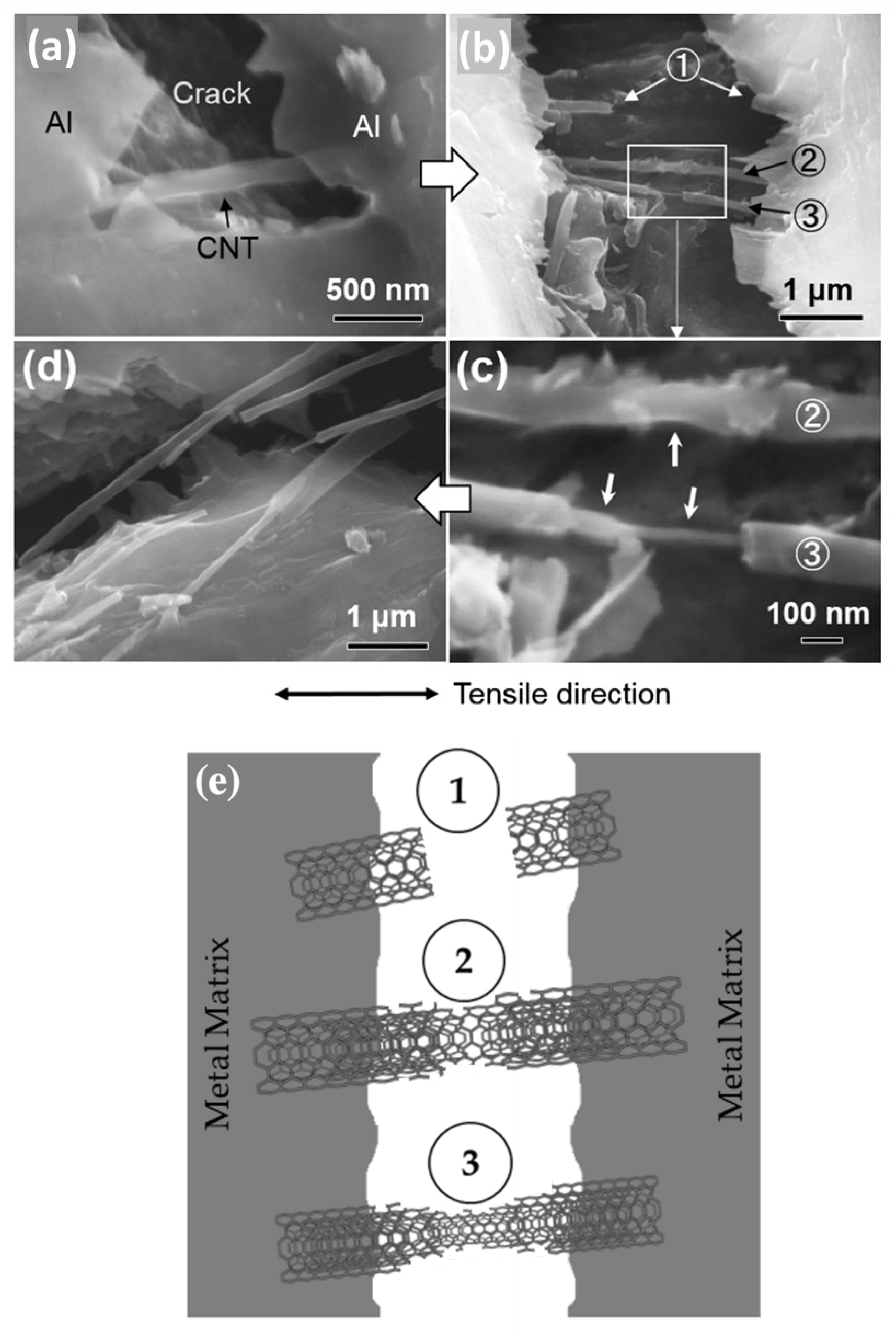
Chen et al. [69] studied the failure behavior of Al matrix composites reinforced with CNTs via in situ SEM tensile testing. The facture observations revealed that the CNTs could fracture in different ways. Figure 7 shows the SEM images of the nanocomposites, revealing the three means of rupture of the CNTs. The fracture surface of the nanocomposites reveals that CNTs (marked as (1)) and experienced a kind of multiple peeling fracture process of the outer walls, marked as (2) and (3) (Figure 7e). This occurred due to the load transfer between the CNT walls. If the CNT presents defects, all its walls will fracture, marked as (1) in Figure 7b. When an effective load transfer occurs, the outer walls of CNT fractures and inner walls form a bridge, as shown by the example marked as (3) in Figure 7c.
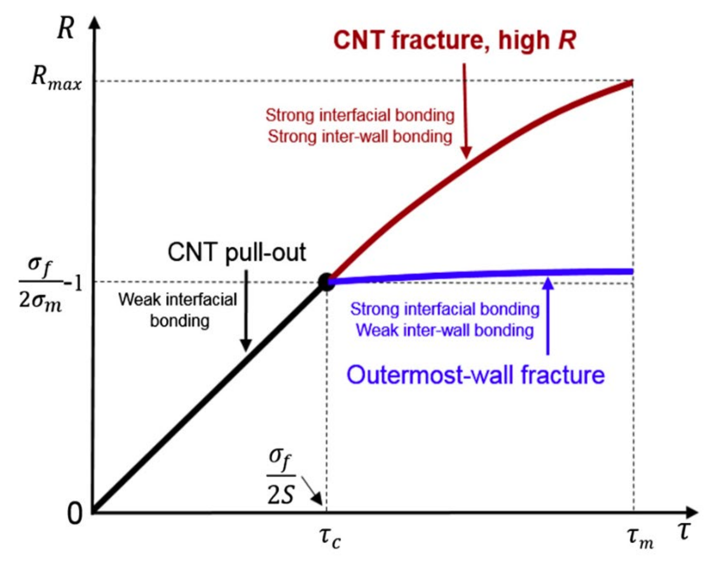
Figure 8 shows the effect of the CNT failure mode proposed by Chen et al. [69] on the strengthening efficiency (R) of composites as a function of interfacial stress (τ) between the CNT and the matrix based on the shear–lag model.
Stress on the CNT comprises two individual stresses, one causing CNT pull-out and the other causing outermost wall fracturing. The R of the outermost wall fracture must be slightly higher than the maximum R in pull-out mode at the critical interfacial stress (τc), due to the small volume fraction of the outermost wall. To determine τc, it is essential to consider the matrix yield strength (σM), the CNT yield strength (σf), and the aspect ratio of the CNT (S). The currently observed CNT fracture mode has the highest R. In this mode, because R increases with the increase in τ, the maximum R (Rmax) is attained when τ reaches its maximum value, τm. When all walls of the CNT fail in the same mode, pull-out or CNT fracture will occur depending on the interface bonding. However, outermost wall fractures occur when the tensile load is effectively transferred to the outer wall via strong interfacial stress but is insufficient between walls.
Zhou et al. [79] performed the in situ characterization of interfacial shear strength in carbon nanotube-reinforced aluminum matrix composites. A scheme of the behavior of a CNT during the fracture of an Al matrix after tensile testing can be seen in Figure 9. With the additional increase in load displacement, a CNT bridge of a relatively shorter embedded length will be detached and pulled out of the matrix. In this case, the total exposed part of the CNT is on the fracture surface.
The effective embedded length and diameter of the multi-walled carbon nanotubes (MWCNTs) incorporated into the Al matrix were evaluated by observing the pulled out MWCNTs under high-resolution transmission electron microscopy (HRTEM). Figure 10 shows the HRTEM of the CNT embedded in the matrix after and before the tensile tests. When local interfacial slippage occurs, low interface bonding is observed, while the lack of interfacial slippage is associated with high interface bonding between the CNT and matrix.
Boesl et al. [81] also performed in situ tensile tests of Al/CNT nanocomposites to understand the strengthening and deformation mechanisms. The failure occurs via the CNT being pulled out from the Al matrix; however, the telescopic sliding of the CNT walls was also observed, which aids the reinforcement effect.

2.2. Grain Refinement or Texture Hardening

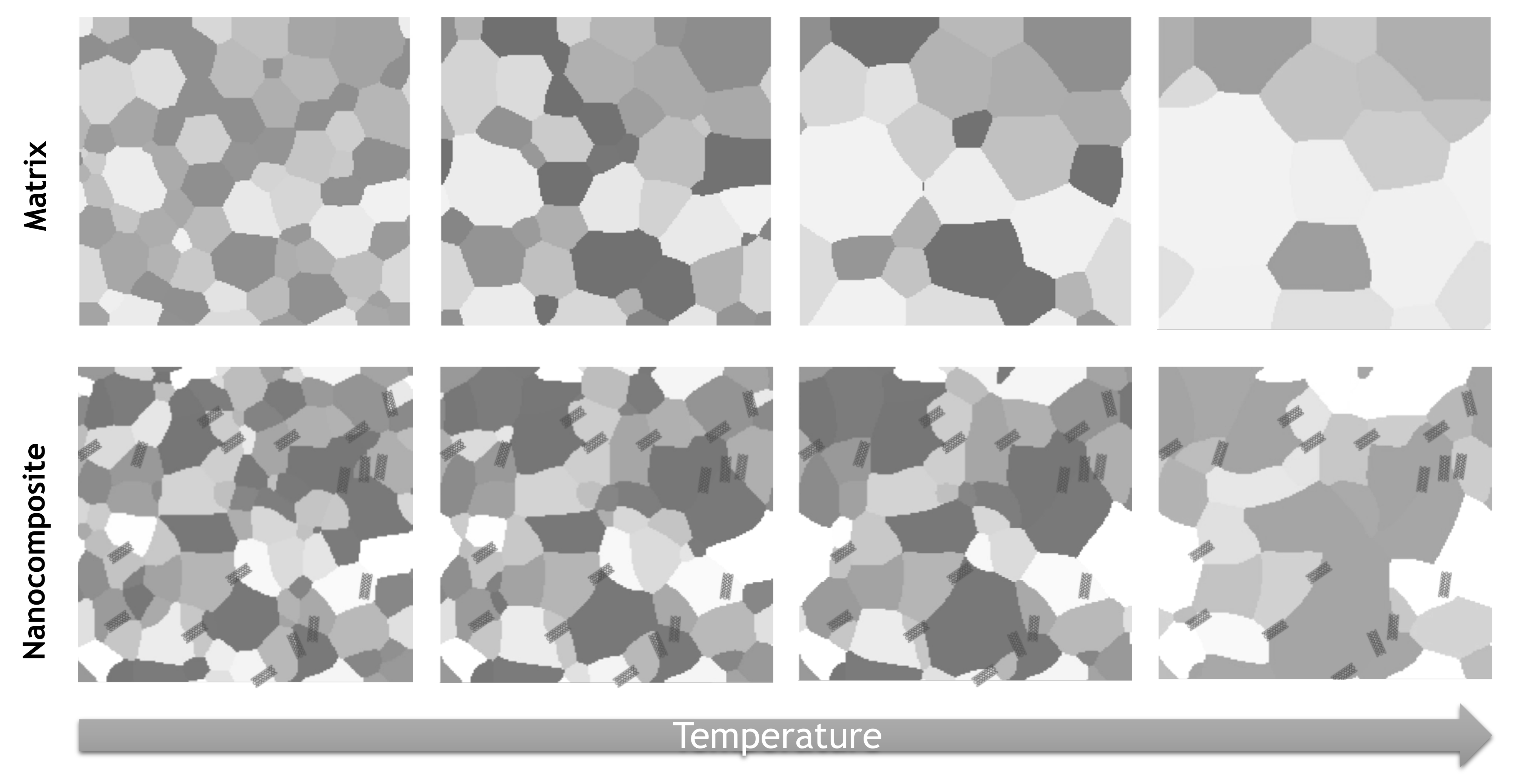
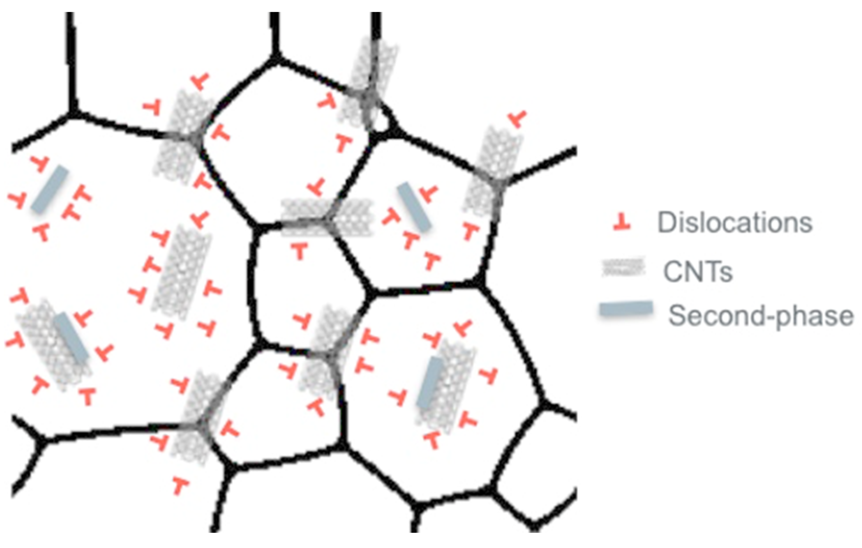
The improvement in the mechanical properties of the nanocomposites can be attributed to the grain refinement resulting from the introduction of the CNTs. The presence of CNTs, mainly at grain boundaries, can significantly affect boundary pinning during production, resulting in smaller grain sizes in the nanocomposites. Grain refinement increases with the increase in the amount of CNTs. Figure 11 shows a schematic of a matrix with and without CNTs. When the matrix with CNTs is subjected to different temperatures during the production process or even in post-processing, the CNTs will affect the grain boundary motion via pinning and rotation, giving rise to a final microstructure with a different grain size or/and orientation.
The Zener pinning equation (2) can estimate the mean grain size (D) of the composites:
D = k r f n ,
where k is a proportional dimensionless constant, f is the volume fraction of the reinforcement, n is the exponent for f in the general form of the Zener equation, and r is the mean reinforcement radius. The CNTs acts as a frictional force against the grain boundary migration and hinder grain growth. Grain refinement depends on the CNTs’ diameters, quantity, and length. A smaller diameter, greater quantity, and shorter CNTs promote a stronger pinning effect, which results in a smaller grain size of the composite.
Grain refinement or modification in the crystallographic orientation of the nanocomposites compared to the unreinforced material can allow for microstructural tailoring and, consequently, control of its properties. For metal matrix composites reinforced with CNTs, grain refinement strengthening has been identified in several different matrices such as Al [82,83,84], Cu [85,86], Ni [87,88,89], and Al alloys [90,91]. It has been observed that an increment in the relative CNT volume manifests an improvement in the mechanical properties (hardness and/or yield strength) due to microstructural refinement.
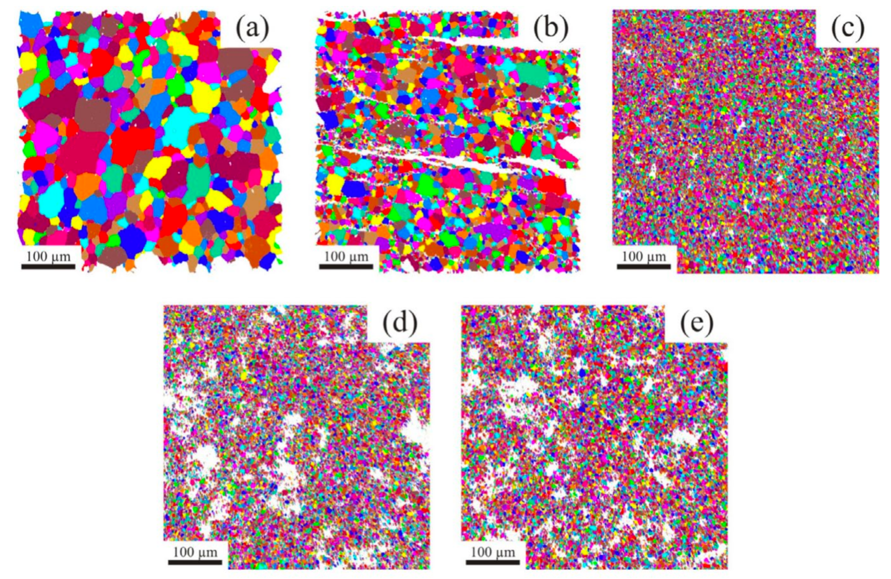
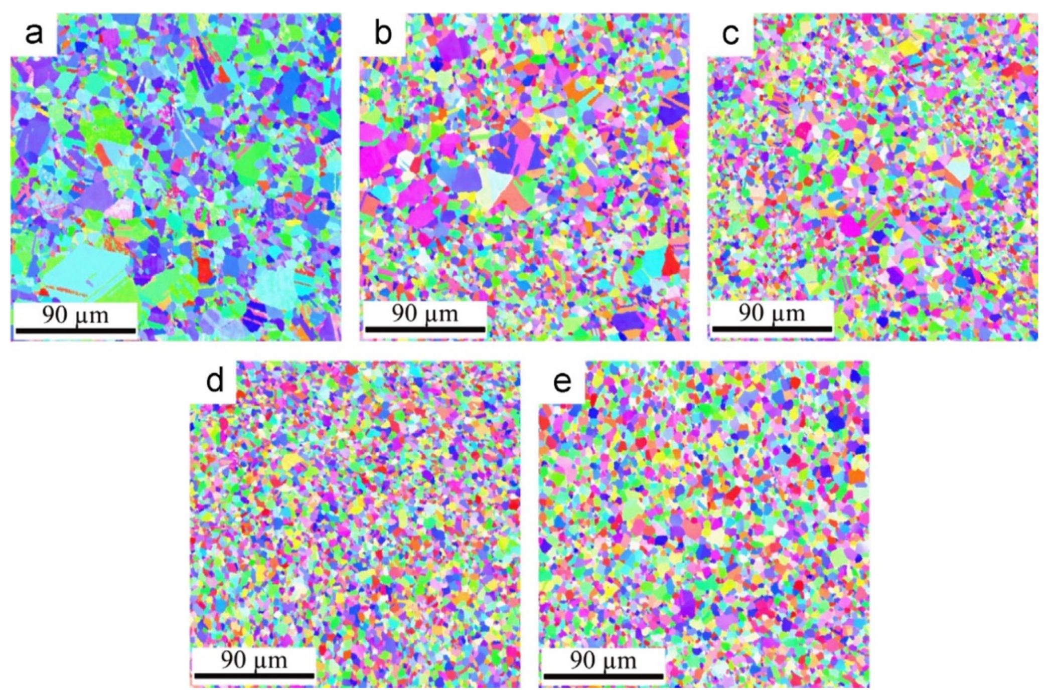
Suarez et al. [87] investigated the grain sizes of Ni/CNT nanocomposites produced by cold pressing under 990 MPa and sintering at 6.5, 12, 18, and 27 vol.% CNTs. Figure 12 shows the electron backscatter diffraction (EBSD) results of the Ni and Ni/CNT with varying CNTs produced under the same conditions. The grain sizes decrease with the increase in the CNT volume fraction. Another important factor is that, for the nanocomposites, the quantity of pores also increases with the increase in the CNT fraction. This can be due to the difficulty of the dispersion of a large quantity of CNTs. Moreover, no significant change in the final size is observed in the 27 vol.% sample compared to the 12 and 18 vol.% samples.
Figure 13 shows the inverse pole figure maps of the Ni/CNT nanocomposites produced at different volume fractions by Suarez et al. [88] via the powder metallurgy route. The introduction of CNTs changes the grain size of the nanocomposite, as well as the grain orientation. For the Ni sample, produced under the same conditions, the predominant colors of the grains are purple, blue, and green, while the nanocomposites manifest other colors. This means that during sintering, due to the presence of CNTs, the grain boundary mobility and grain rotation are different, resulting in samples with different crystalline orientations. Grain size and texture are essential microstructural characteristics because they directly affect the mechanical properties of materials, and can be considered reinforcement mechanisms in nanocomposites reinforced with carbon nanotubes.

2.3. Second Phase Hardening

Due to the thermal decomposition of the structure of the CNTs, a chemical reaction between the CNTs and the metallic matrices can occur. The production conditions have a significant effect on the extension of this reaction. This depends on the free energy of the reaction and the processing technology used, the temperature and pressure used, the degree of CNT structural damage that can occur during the dispersion/mixture processes, and the matrix material used [56].
The formation of a second phase can improve the interface’s shear strength, resulting in an effective load transfer mechanism. Besides this, the second phase will interact with dislocations and even grain boundary motion, increasing the nanocomposite’s strength [55,56,65,92,93].
A chemical reaction can occur, causing the total transformation of the CNTs (full reaction) or a partial transformation of the CNTs (partial reaction), resulting in the formation of carbides [55,56,74,92,93,94]. The kind of reaction will directly determine the type of strengthening mechanism that will most contribute to improving the properties of the nanocomposite. If a partial transformation occurs, the interface between the CNT and the matrix will become stronger, enhancing the load transfer mechanism. On the other hand, if the transformation is complete, hardening due to the presence of a second phase will have a greater contribution.
For a pure Al matrix reinforced with CNTs, the formation of Al4C3 is commonly reported [55,56,74,92,93,94]. The formation, volume fraction, morphology, and size of this intermetallic phase strongly depend on the temperature used for the fabrication, the type and size of the CNTs, and the pre- and post-treatments. At elevated temperatures, this carbide probably forms as the free energy of the reaction is negative at the melting temperature of the Al.
Different morphologies of Al4C3 have been observed: (1) whisker-like, (2) dumbbell-like, (3) needle-like, and (4) tube-like.
Most studies state that the presence of Al4C3 can improve the interface between the CNTs and the Al matrix, leading to a more effective load transfer [74,92,93]. Although the interaction of the carbide with the dislocation motion leads to an increase in the density near these particles affects the nanocomposites’ mechanical properties. Nevertheless, the strengthening effect will be influenced by the thickness of the Al4C3.
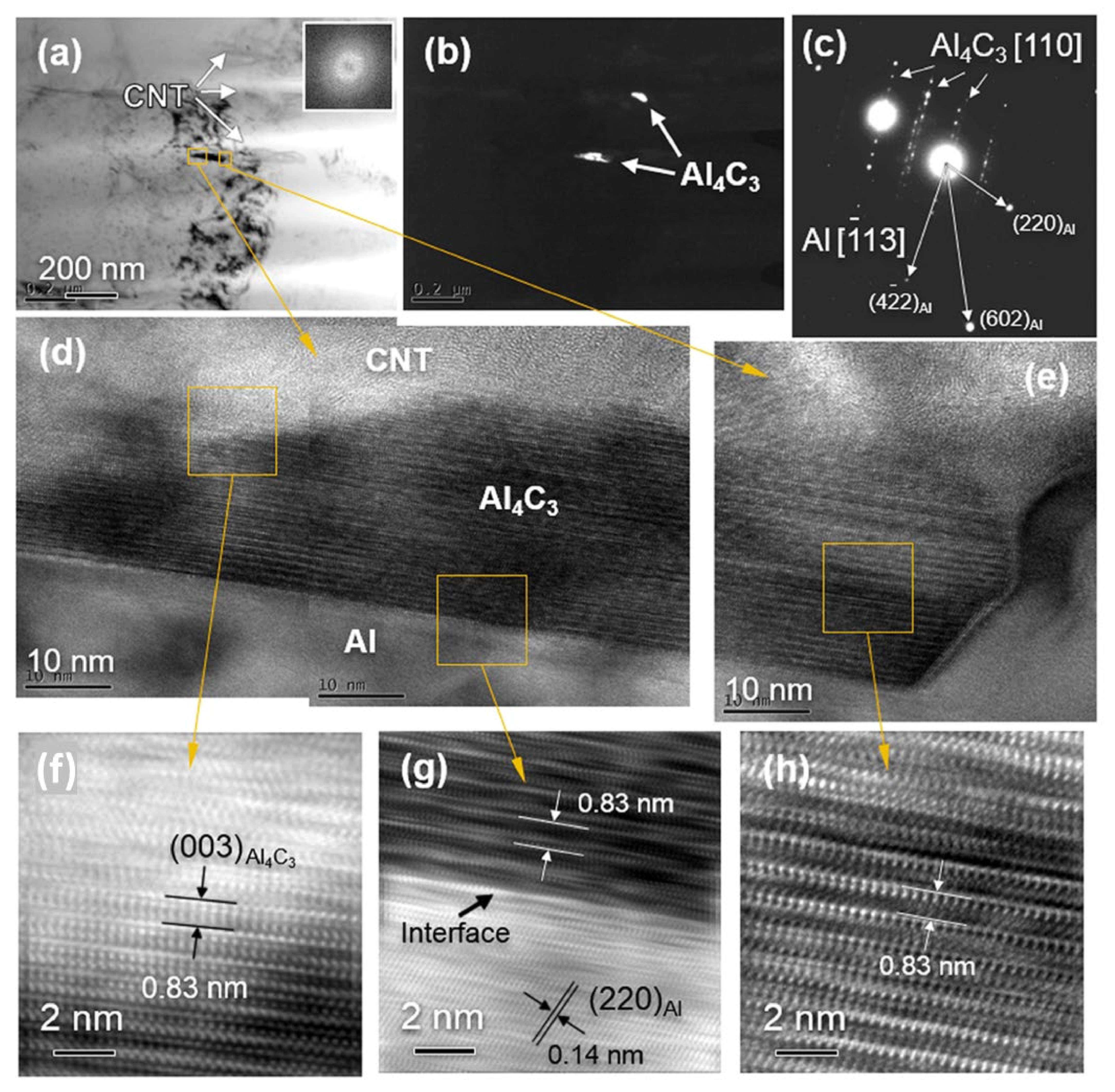
Figure 14 shows transmission electron microscopy (TEM) and HRTEM images of the Al/CNT nanocomposites produced via powder metallurgy by Chen et al. [74]. These images show the interfacial interaction between the CNT and the matrix, showing the Al4C3 formation that is often observed near the ends of the CNTs. However, the middle part was also detected, but this strongly depended on the composites’ production conditions.
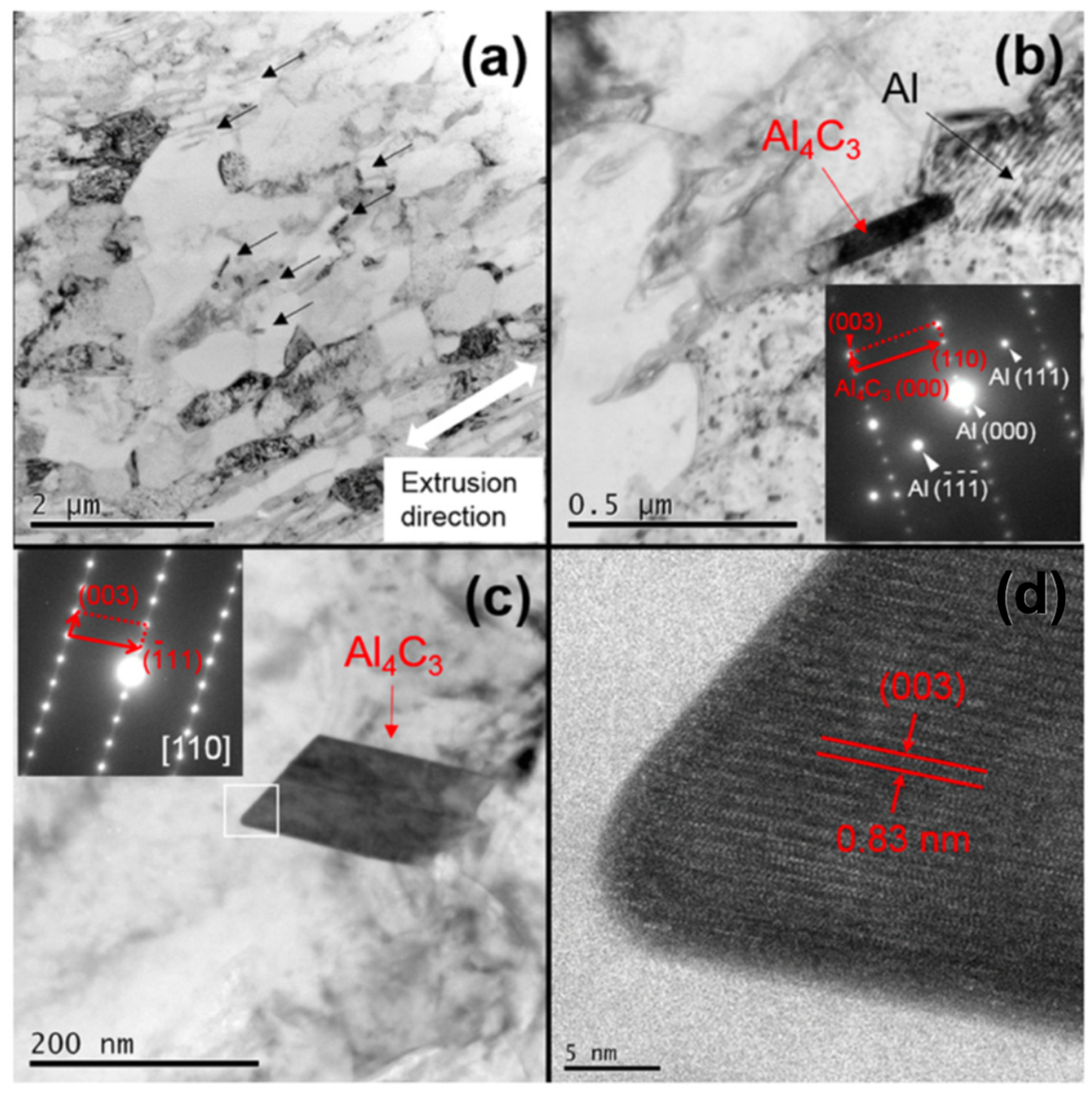
In another work by Chen et al. [94], the authors investigated the in situ-synthesized Al4C3 in the context of strengthening aluminum matrix composites. The authors produced nanocomposites with the CNTs, and then induced the chemical reaction to form the Al4C3. Figure 15 shows a TEM observation of the Al4C3 formed. The tensile tests demonstrated that high strength, high Young´s modulus, and good elongation could be achieved via a strong bonding interface between the Al4C3 and Al matrix.
Guo et al. [95] also investigate the effects of the Al4C3 on the mechanical properties of Al-based composites reinforced with CNTs and SiC. The authors state that the size and amount of Al4C3 depend on the temperature of the composite’s post-heat treatment (spark plasma sintering (SPS) and hot-rolling). Nanosized Al4C3 has a positive effect on the mechanical properties of composites since it improves interfacial bonding. On the contrary, microsized Al4C3 has a negative effect on the mechanical properties of the composites.
When other Al alloys besides Al4C3 are used in the matrix, other reactions can occur. For instance, Bakshi et al. [61] observed the formation of SiC and Al4C3 in an Al-Si alloy matrix composite reinforced by carbon nanotubes.
In CNT-reinforced Ti matrix nanocomposites, TiC is the most commonly reported second phase observed due to the chemical reaction, and is commonly formed at the grain boundaries of the Ti matrix [38,58,59]. Kondoh et al. [38] showed the formation of spherical and elongated particles of TiC. The morphology of the particles will depend on the type of CNTs, and the type of processing technique used. For instance, the spherical form can be observed when using MWCNTs, and they are elongated when plastic deformation is used to produce the composites. As with the Al4C3 phase formed in the Al matrix, the TiC phase is formed as a result of the elevated temperatures required to produce the Ti metal matrix nanocomposites. Some authors [38,58] refer to the positive influence of the presence of TiC on the mechanical properties of nanocomposites. The higher the volume fraction of incorporated CNTs, the better the mechanical properties of the composites.
Although it is not possible to form a second phase between Ni and CNTs due to the negative Gibbs energy, in some works, the appearance of a Ni3C phase is reported. This can be explained by the defects in the CNTs, which result in elevated temperatures and demanding dispersion/mixture conditions. Hwang et al. [75] observed the formation of an intermetallic compound at the interface of a pure Ni matrix reinforced by CNT. The formation of a metastable hexagonal Ni3C at the defect sites of the carbon nanotube can significantly improve the mechanical properties of the nanocomposites, as reported for Al and Ti matrices reinforced by CNTs.
For Mg and Cu pure matrix composites reinforced with CNTs, due to the low wettability and poor compatibility between the CNT and metal matrix, we should not expect the formation of carbides [56]. Improvements in the dispersion and bonding between the CNTs and matrix can be achieved by coating the CNTs. The reaction occurs between the coating and the metal matrix. The problem is significant for the Cu metal matrix, since a reaction is not expected, but the formation of cracks between the CNT and metal matrix is. This problem can also be overcome by alloying the Cu matrix with carbide-forming elements such as Cr and Ti. The improvement in the strength of these nanocomposites is lower than that for Al/CNT, Ti/CNT, and Ni/CNT due to the poor transfer of stress at the interface of the reinforcement and this metal matrix.
For the Mg-Al alloy matrix composite coating, several intermetallic phases were observed depending on the chemical composition [96], due to the easy formation of Al-Mg-C carbides. For Cu metal matrix composites, adding alloy elements could be an excellent way to improve the interfacial bonding between the CNT and metal matrix [97].
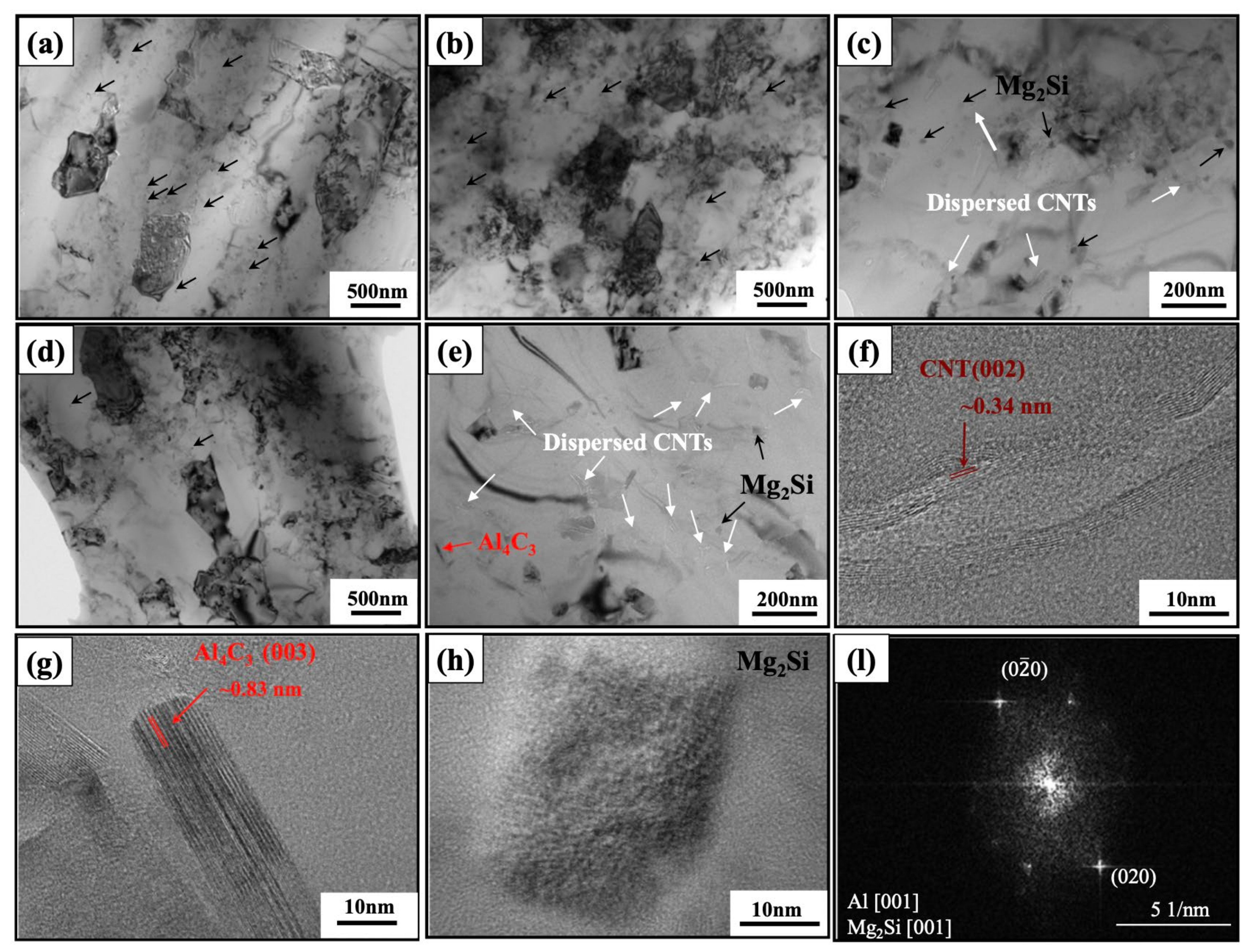
The presence of CNTs in the alloy matrix composites can also affect the precipitate-phase alloy. Figure 16 shows an example observed by Chen et al. [98], here involving 6061Al/CNT. TEM and HRTEM observations revealed dispersed CNT in the matrix. Mg2Si can also be observed. The introduction of the CNTs induces a reduction in the content of the Mg2Si phase. The presence of Al4C3 can also be identified via the reaction between the CNT and matrix.

2.4. Strain Hardening

The increase in dislocation density due to the presence of the CNTs in metal matrices can occur due to the interaction of the CNTs with the dislocation motion and the thermal mismatch between the CNT and matrix. Furthermore, this effect is enhanced due to the presence of the second phase, which results from the reaction between the CNT and the matrix. Figure 17 is a schematic showing the presence of pinned dislocation inside the grains, due either to the presence of CNTs or to the particles partially or totally formed at the interface between the CNTs and the matrix. The Orowan mechanism occurs when the dislocation motion is affected by the presence of CNTs on the metal matrix. Residual dislocation loops close to the CNTs result in back stress formation [67]. The dislocation loops result in strengthening and contribute to the improvement of the properties of the composites.
The significant difference in the thermal expansion coefficient (CTE) between the CNTs and the metal matrices can also increase dislocation density. This can be attributed to the high internal stress observed in the composites and the dislocation generated around the reinforcement to reduce the stored energy. This occurs during the cooling to room temperature in the production of the nanocomposite. An apparent thermal mismatch strengthening effect is reported for the nanocomposites produced via techniques that require higher rolling rates.
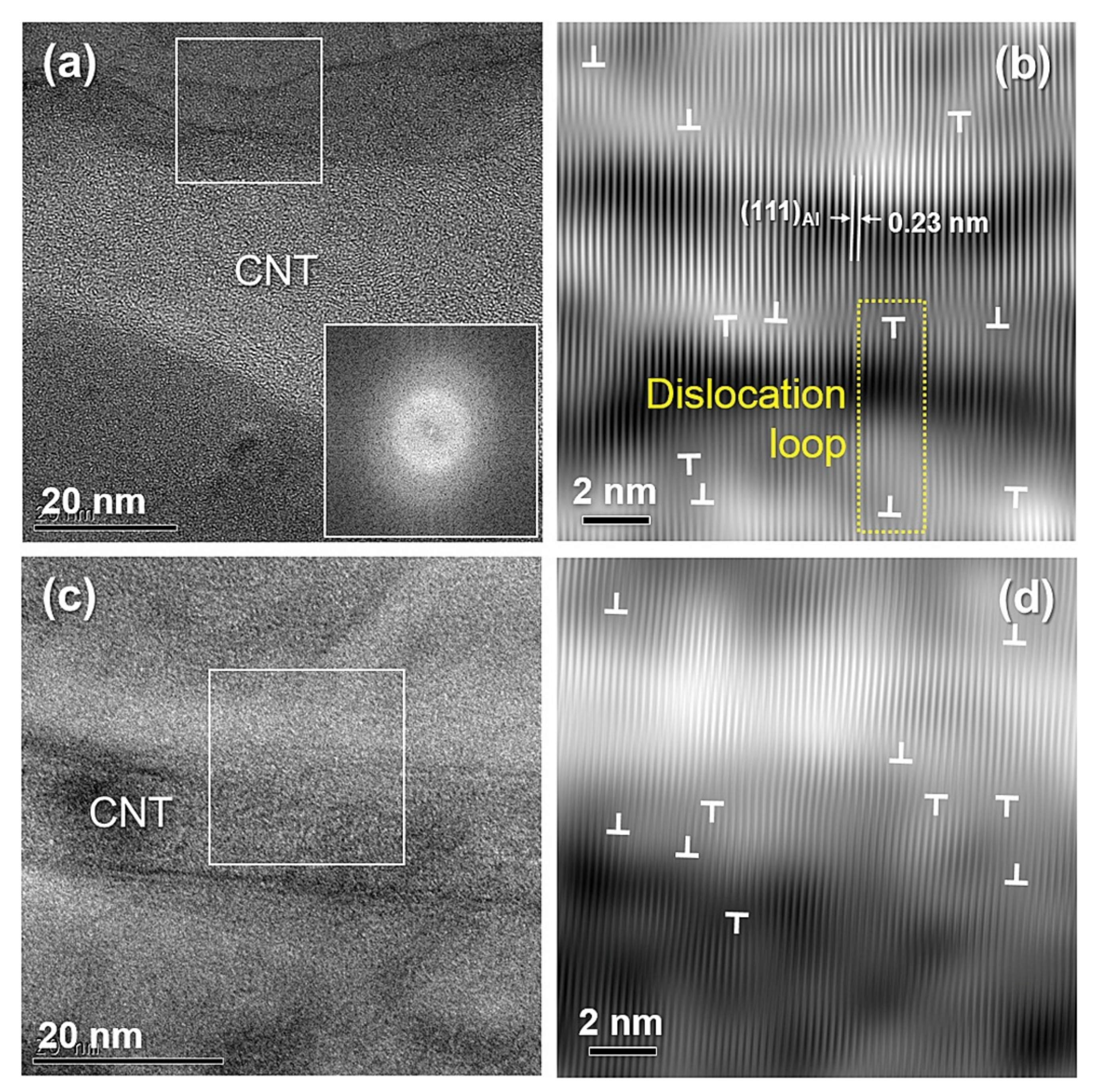
Chen et al. [99] observed by TEM and HRTEM the effect of thermal mismatch on increasing the dislocation near the CNT interface and the Al matrix. The nanocomposites were produced by spark plasma sintering followed by hot extrusion. In Figure 18, a few dislocations observable at the CNT/matrix interface can be explained by the low cooling rate used in the hot extrusion process.
The conditions of the interaction of a second phase particle or precipitates with the dislocation motion are already well known, but those of CNTs are not. However, some researchers have dedicated themselves to investigating, through in situ tests, the interaction of CNTs with the movement of dislocation. So et al. [100] studied the interaction between CNTs and an Al matrix during an in situ tensile rupture test by TEM. The TEM observation during the in situ tests indicates that the CNT promotes the pinning of the dislocation motion. For understanding the CNTs’ influence on the Orowan strengthening mechanism, it is vital to consider their aspect ratio and their volume fraction in the matrix. Short CNTs with a length (LCNT) much smaller than the dislocation (Ldislocation) will behave like particles that can trap loops [99,100].
Xu et al. [101] also investigated the strain hardening in Al/CNT nanocomposites produced by sintering following hot extrusion. The authors produced nanocomposites using different extrusion temperatures to achieve different Al grain sizes in the matrix samples (350, 320, and 300 °C), and two different volume fractions of CNTs (1.00 and 2.00 vol.%). The microstructure-based strain hardening model was developed by modifying and combining the Kocks–Mecking approach of dislocation density evolution, the back stress models for grain boundaries, and the back stress models for the second phases (Figure 19). For the low-aspect ratio CNTs, the Orowan mechanism is essential to the strengthening improvement.
The interaction between the CNTs and the dislocation motion depends on the aspect ratio of the CNTs. While for those with a low aspect ratio, the Orowan mechanism is observed, for those with a higher aspect ratio, the dislocation pinning of the nanocomposites is observed. This effect also contributes to the increase in the dislocation density and the strain hardening of the nanocomposites.
Some works state that for nanocomposites reinforced with CNTs, an increase in low-angle grain boundaries is observed, combined with regions with high misorientation.
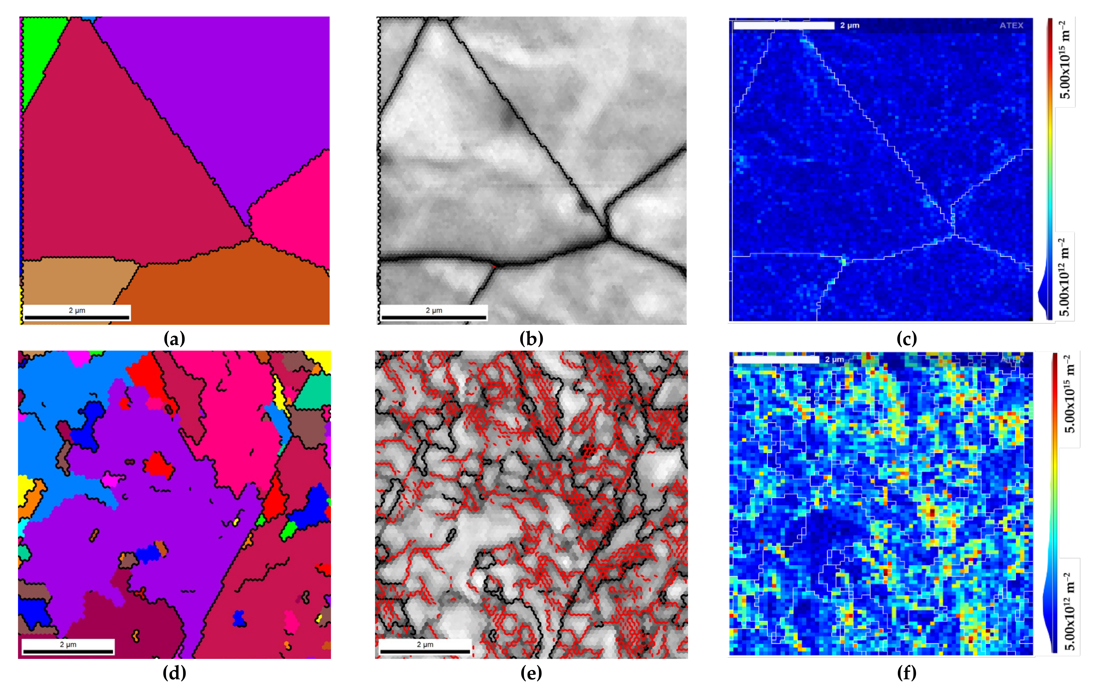
Carneiro et al. [102,103] showed that introducing CNTs into metallic matrices induces an increase in the low-angle grain boundaries associated with the dislocation density. The nanocomposites were produced via powder metallurgy, and during the mixture and dispersion, the authors reported an increase in plastic deformation. The microstructure of the sintered samples revealed a decrease in the dislocation density during the sintering since the activation of recovery and recrystallization mechanisms promotes dislocation annihilation. In nanocomposites, high estimation of geometrically necessary dislocation (GND) density is observed, mainly close to the CNT clusters.
Figure 20 shows the high-magnification EBSD maps of Ni and Ni/CNT, and the GND density maps [104], which demonstrate that for the nanocomposites produced by powder metallurgy, a higher density of dislocations is observed.
Chen et al. [105] performed in situ observations to understand the effects of the increase in the low-angle grain boundaries (LAGB) associated with dislocation density for the Al/CNT nanocomposites. The nanocomposites were produced by SPS following hot extrusion. Figure 21 shows the TEM results from the in situ high-temperature TEM study performed on the TEM sample of the Al/CNT composite sintered at 526.85 °C (800 K). Well-dispersed and unreacted CNTs are observed in the Al matrix in the initial state. As the temperature increases to 576.85 °C (850 K), a dislocation band (the black arrows in Figure 21c) moves to the position shown by the red arrow in Figure 21d, which is pinned by CNTs. The grey contractions surrounding the CNTs result from the strain at the Al/CNT interface because of the significant difference in the thermal expansion coefficients between the Al and CNTs. Even at higher temperatures (626.85 °C), the dislocation no long moves forward, and stays steady when in contact with CNTs (Figure 21e). After cooling down, a LAGB with a misorientation angle of ~4° forms.

3. Contributions of the Different Strengthening Mechanisms

The strengthening of the metal matrix composites by CNT can be achieved by different mechanisms. Depending on the metal and the production technique, the different mechanisms can affect the contribution, significance, and relationship of the total reinforcement of the composite. This section aims to describe the contribution of the different mechanisms to the strengthening of the metal matrix nanocomposites reinforced by CNTs.
To fully understand the effects of the microstructure on the strength of composites, the contribution of the related strengthening mechanisms to the yield strength is quantitatively calculated. Based on the available literature and the obtained microstructures, the enhanced yield strength should be derived from the sum of the yield strength of the unreinforced matrix and the strengthening mechanisms.
The contributions of the different strengthening mechanisms will depend on the volume fraction of the CNTs, the interface bonding of the CNT, the use of a pure or alloyed matrix, and the aspect ratio of the CNTs.
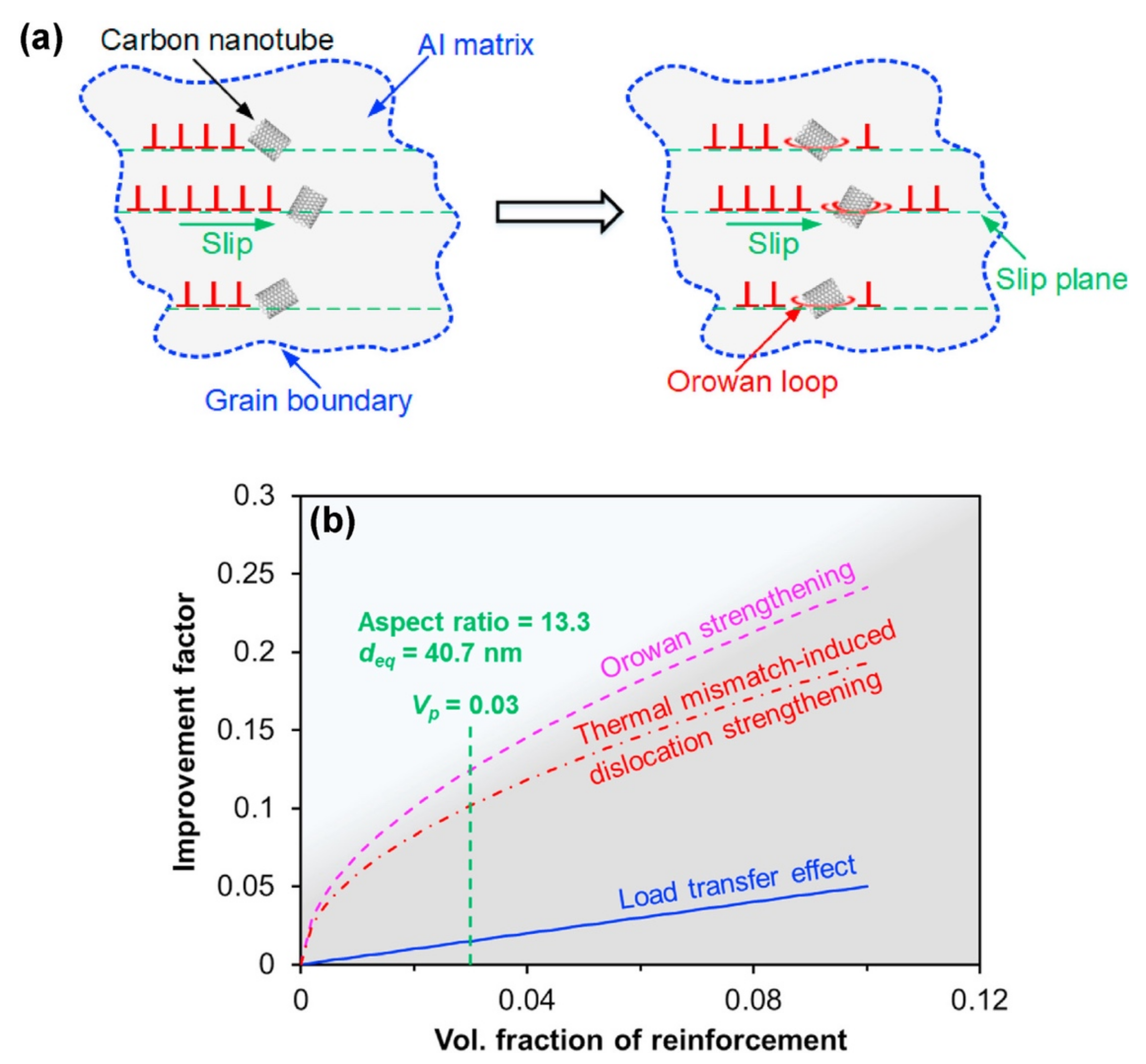
The aspect ratio of the CNTs will determine the type of interaction between the CNTs and dislocations. At a lower aspect ratio, the Orowan mechanism is predominant. A schematic showing the Orowan looping mechanism after dislocations gliding over and bypassing the CNTs can be observed in Figure 22a.
The individual contributions of these strengthening mechanisms concerning the volume fraction of CNTs, calculated by Mohammed et al. [106], are presented in Figure 22b. All the contribution factors increase with increasing volume fraction. The strengthening contribution is relatively low from the load transfer and is high from the Orowan strengthening mechanism, while the contribution of thermal mismatch-inducing dislocation strengthening lies in the middle. The relatively low contribution of load transfer is related to the equivalent spherical particle consideration. This investigation was performed for CNT-reinforced bimodally grained aluminum matrix nanocomposites.
Guo et al. [107] investigated the synergic strengthening effects of stacking faults in carbon nanotube-reinforced aluminum matrix composites on enhanced mechanical properties. The results also demonstrate that with the increase in CNT volume fraction, the contributions of grain refinement, Orowan looping, load transfer, and stacking fault to the experimentally improved yield strength all monotonically increase, resulting in the obtaining of better mechanical properties.
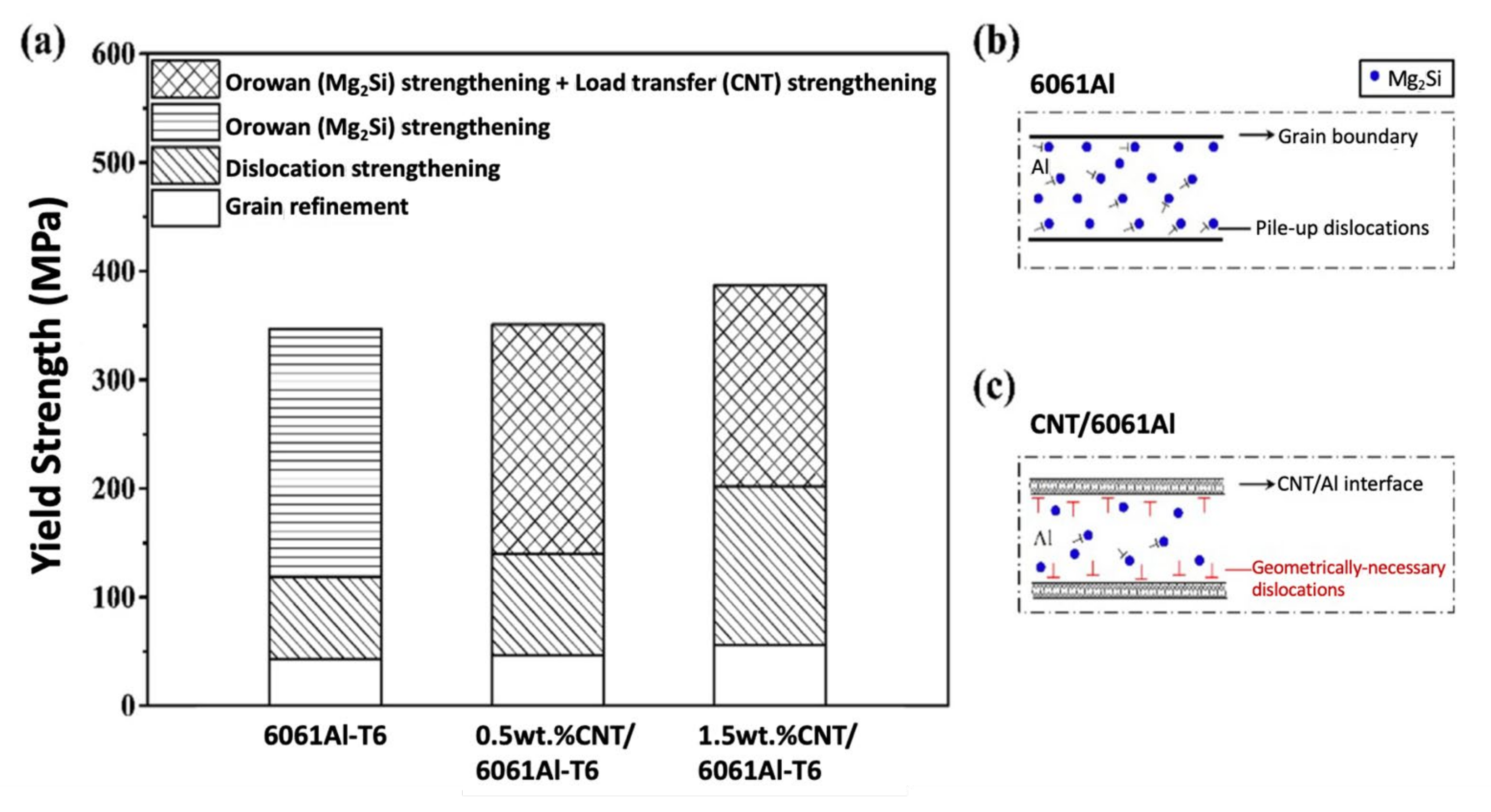
Chen et al. [98] showed that for 6061Al/CNT, the increase in the amount of CNT can significantly refine the grain size of the matrix and increase the dislocation density, as can be observed in Figure 23a. For the 6061 Al alloy, the dislocation motion is hindered by dispersed Mg2Si particles (Orowan reinforcement, Figure 23b). At the same time, for the 6061Al/CNT composites, beyond this effect, the CNTs located mainly at the grain boundaries exert a load transfer strengthening effect (Figure 23c).
The interfacial bonding between the CNTs and matrix also plays a critical role in determining the strengthening effect. Generally, a strong transition interface is required between the matrix and the CNTs to form a strong bond.
The CNT–metal interface is characterized as mechanically bonded when there is no interfacial reaction. Typically, this bond is relatively weak due to the significant surface energy difference between the matrix and the CNTs. When the formation of a suitable carbide occurs following an interfacial chemical reaction and is characterized as a chemical bond, the bonding of the interface between the CNTs and the matrix is characterized as stronger.
For instance, Chen et al. [74] showed that grain refinement contributed a small portion to the strengthening of the Al/CNT composites produced by powder metallurgy at a sintering temperature range of 426.85–626.85 °C. On the other hand, the load transfer of CNTs mainly contributed to the total strength of the nanocomposites, and this was dependent on sintering temperatures. At low sintering temperatures, the CNTs were stable in the nanocomposites, and a low number of nanoparticles of Al4C3 were observed at the interface between the CNT and matrix. At medium sintering temperatures, the quantity of Al4C3 nanoparticles increased at the interface between partially reacted CNTs and the Al matrix. Pull-out was identified as the failure mechanism of CNTs from in situ tensile studies. The interface strength and load transfer efficiency were increased significantly compared to low-temperature-sintered composites. At high temperatures, some mono-crystal Al4C3 phases with rod shapes were formed in the Al matrix, resulting in a decreased strengthening effect. Therefore, it is expected that partially reacted CNTs with interfacial carbides may possess an ideal reinforcement structure for achieving a high load transfer efficiency in the nanocomposites.

4. Conclusions

In recent years, research on metallic matrix nanocomposites reinforced with carbon nanotubes has been widely pursued. This is due to the considerable potential for developing advanced components with unique mechanical properties that can boost the transport industry market via the construction of lightweight and strong components. However, the studies show that the mechanical properties obtained are not as good as they could be, even though nanocomposites have better properties than matrices without the introduction of CNTs. This is because the strengthening mechanisms depend on many factors, and there is still a lack of knowledge about how they act in these nanocomposites. These mechanisms will depend on the type of matrix, and therefore different matrices present different reinforcement potentials, related to the different production and dispersion methods. The main strengthening mechanisms that may improve the properties of nanocomposites are load transfer, grain refinement or texture strengthening, second phase hardening, and strain hardening. Load transfer is the most commonly reported strengthening mechanism for metal matrix nanocomposites reinforced by CNTs. This mechanism occurs by transferring the load from the matrix to the CNTs through their interface, and depends on the bonding strength between the reinforcement and matrix, as well as the CNTs’ volume fraction and aspect ratio. The mechanical properties can also be improved by decreasing the grain size of the matrix by including more CNTs, mainly at grain boundaries, which can significantly affect the boundary pinning during production, resulting in a smaller grain size for the nanocomposites. Chemical reactions between the CNTs and the metallic matrices can occur due to the thermal decomposition of the structure of the CNTs, forming a second phase that also contributes to the improvement of the mechanical properties of the nanocomposites. The increase in dislocation density due to the presence of CNTs on the metal matrices can occur due to the interaction of the CNTs with the dislocation motion and the thermal mismatch between the CNT and the matrix. The contributions of the different strengthening mechanisms will depend on the volume fraction of the CNTs, the interface bonding of the CNT, the use of pure or alloyed matrix, and the aspect ratio of the CNTs.

Author Contributions

Conceptualization, Í.C. and S.S.; validation, S.S.; investigation, Í.C. and S.S.; writing—original draft preparation, Í.C. and S.S.; writing—review and editing, Í.C. and S.S.; supervision, S.S. All authors have read and agreed to the published version of the manuscript.

Funding

This research was funded by the Portuguese Foundation for Science and Technology (FCT), through PhD grant attributed to Íris Carneiro, with the reference PD/BD/143030/2018, and the P2020|Norte2020 program with the reference NORTE-08-5369-FSE-000051.

Institutional Review Board Statement

Not applicable.

Informed Consent Statement

Not applicable.

Data Availability Statement

Data are available upon request from the authors.

Conflicts of Interest

The authors declare no conflict of interest.

References

  1. Xu, C.L.; Wei, B.Q.; Ma, R.Z.; Liang, J.; Ma, X.K.; Wu, D.H. Fabrication of Aluminum–Carbon Nanotube Composites and Their Electrical Properties. Carbon 1999, 37, 855–858. [Google Scholar] [CrossRef]
  2. Zhong, R.; Cong, H.; Hou, P. Fabrication of Nano-Al Based Composites Reinforced by Single-Walled Carbon Nanotubes. Carbon 2003, 41, 848–851. [Google Scholar] [CrossRef]
  3. Laha, T.; Agarwal, A.; McKechnie, T.; Seal, S. Synthesis and Characterization of Plasma Spray Formed Carbon Nanotube reinforced Aluminum Composite. Mater. Sci. Eng. A 2004, 381, 249–258. [Google Scholar] [CrossRef]
  4. Noguchi, T.; Magario, A.; Fukuzawa, S.; Shimizu, S.; Beppu, J.; Seki, M. Carbon Nanotube/Aluminum Composites with Uniform Dispersion. Mater. Trans. 2004, 45, 602–604. [Google Scholar] [CrossRef] [Green Version]
  5. Laha, T.; Agarwal, A.; McKechnie, T. Comparative Evaluation of Plasma and High Velocity Oxy-Fuel Spray Formed Carbon Nanotube Reinforced Al-Based Composite. In Surface Engineering in Materials Science-III.; Agarwal, A., Dahotre, N.B., Seal, S., Moore, J.J., Blue, C., Eds.; The Minerals, Metals and Materials Society: Warrendale, PA, USA, 2005. [Google Scholar]
  6. He, C.; Zhao, N.; Shi, C.; Du, X.; Li, J.; Li, H.; Cui, Q. An Approach to Obtaining Homogeneously Dispersed Carbon Nanotubes in Al Powders for Preparing Reinforced Al-Matrix Composites. Adv. Mater. 2007, 19, 1128–1132. [Google Scholar] [CrossRef]
  7. Deng, C.F.; Zhang, X.X.; Ma, Y.X.; Wang, D.Z. Fabrication of Aluminum Matrix Composite Reinforced with Carbon Nanotubes. Rare Met. 2007, 26, 450–455. [Google Scholar] [CrossRef]
  8. Zhou, S.-M.; Zhang, X.-B.; Ding, Z.-P.; Min, C.-Y.; Xu, G.-L.; Zhu, W.-M. Fabrication and Tribological Properties of Carbon Nanotubes Reinforced Al Composites Prepared by Pressureless Infiltration Technique. Compos. Part A Appl. Sci. Manuf. 2007, 38, 301–306. [Google Scholar] [CrossRef]
  9. Deng, C.F.; Zhang, X.X.; Wang, D.Z.; Lin, Q.; Li, A.B. Preparation and Characterization of Carbon Nanotubes/Aluminum Matrix Composites. Mater. Lett. 2007, 61, 1725–1728. [Google Scholar] [CrossRef]
  10. Deng, C.F.; Wang, D.Z.; Zhang, X.X.; Li, A.B. Processing and Properties of Carbon Nanotubes Reinforced Aluminum Composites. Mater. Sci. Eng. A 2007, 444, 138–145. [Google Scholar] [CrossRef]
  11. Esawi, A.M.K.; Borady, M.A.E. Carbon Nanotube-Reinforced Aluminum Strips. Compos. Sci. Technol. 2008, 68, 486–492. [Google Scholar] [CrossRef]
  12. Choi, H.J.; Kwon, G.B.; Lee, G.Y.; Bae, D.H. Reinforcement with Carbon Nanotubes in Aluminum Matrix Composites. Scr. Mater. 2008, 59, 360–363. [Google Scholar] [CrossRef]
  13. Tokunaga, T.; Kaneko, K.; Horita, Z. Production of Aluminum-Matrix Carbon Nanotube Composite Using High Pressure Torsion. Mater. Sci. Eng. A 2008, 490, 300–304. [Google Scholar] [CrossRef]
  14. Lim, D.K.; Shibayanagi, T.; Gerlich, A.P. Synthesis of Multi-Walled CNT Reinforced Aluminum Alloy Composite via Friction Stir Processing. Mater. Sci. Eng. A 2009, 507, 194–199. [Google Scholar] [CrossRef]
  15. Dong, S.R.; Tu, J.P.; Zhang, X.B. An Investigation of the Sliding Wear Behavior of Cu-Matrix Composite Reinforced by Carbon Nanotubes. Mater. Sci. Eng. A 2001, 313, 83–87. [Google Scholar] [CrossRef]
  16. Tu, J.P.; Yang, Y.Z.; Wang, L.Y.; Ma, X.C.; Zhang, X.B. Tribological Properties of Carbon-Nanotube-Reinforced Copper Composites. Tribol. Lett. 2001, 10, 225–228. [Google Scholar] [CrossRef]
  17. Kim, K.T.; Lee, K.H.; Cha, S.I.; Mo, C.B.; Hong, S.H. Characterization of Carbon Nanotubes/Cu Nanocomposites Processed by Using Nano-Sized Cu Powders. Mater. Res. Soc. Symp. Proc. 2004, 821. [Google Scholar] [CrossRef]
  18. Chen, X.H.; Li, W.H.; Chen, C.S.; Xu, L.S.; Yang, Z.; Hu, J. Preparation, and Properties of Cu Matrix Composite Reinforced by Carbon Nanotubes. Trans. Nonferrous Met. Soc. China. 2005, 15, 314–318. [Google Scholar]
  19. Kim, K.T.; Cha, S.I.; Hong, S.H.; Hong, S.H. Microstructures and Tensile Behavior of Carbon Nanotube Reinforced Matrix Nanocomposites. Mater. Sci. Eng. A 2006, 430, 27–33. [Google Scholar] [CrossRef]
  20. Li, Y.-H.; Housten, W.; Zhao, Y.; Zhu, Y.Q. Cu/Single-Walled Carbon Nanotube Laminate Composites Fabricated by Cold Rolling and Annealing. Nanotechnology 2007, 18, 205607. [Google Scholar] [CrossRef]
  21. Kim, K.T.; Cha, S.I.; Hong, S.H. Hardness and Wear Resistance of Carbon Nanotube Reinforced Cu Matrix Nanocomposites. Mater. Sci. Eng. A 2007, 449–451, 46–50. [Google Scholar] [CrossRef]
  22. Yang, Y.L.; Wang, Y.D.; Ren, Y.; He, C.S.; Deng, J.N.; Nan, J.; Chen, J.G.; Zuo, L. Single-Walled Carbon Nanotube-Reinforced Copper Composite Coatings Prepared by Electrodeposition under Ultrasonic Field. Mater. Lett. 2008, 62, 47–50. [Google Scholar] [CrossRef]
  23. Kim, H.N.; Chang, S.N.; Kim, D.K. Enhanced Microhardness of Nanocrystalline Carbon Nanotube Reinforced Cu Composite Using Planar Shock-Wave Compaction. Scr. Mater. 2009, 61, 871–874. [Google Scholar] [CrossRef]
  24. Li, H.; Misra, A.; Horita, Z.; Koch, C.C.; Mara, N.A.; Dickerson, P.O.; Zhu, Y. Strong and Ductile Nanostructured Cu-Carbon Nanotube Composite. Appl. Phys. Lett. 2009, 95, 071907. [Google Scholar] [CrossRef] [Green Version]
  25. Chen, X.; Zhang, G.; Chen, C.; Zhou, L.; Li, S.; Li, X. Carbon Nanotube Composite Deposits with High Hardness and High Wear Resistance. Adv. Eng. Mater. 2003, 5, 514–518. [Google Scholar] [CrossRef]
  26. Chen, W.X.; Tu, J.P.; Xu, Z.D.; Chen, W.L.; Zhang, X.B.; Cheng, D.H. Tribological Properties of Ni–P-Multi-Walled Carbon Nanotubes Electroless Composite Coating. Mater. Lett. 2003, 57, 1256–1260. [Google Scholar] [CrossRef]
  27. Wang, L.Y.; Tu, J.P.; Chen, W.X.; Wang, Y.C.; Liu, X.K.; Olk, C.; Cheng, D.H.; Zhang, X.B. Friction and Wear Behavior of Electroless Ni-Based CNT Composite Coatings. Wear 2003, 254, 1289–1293. [Google Scholar] [CrossRef]
  28. Yang, Z.; Xu, H.; Li, M.K.; Shi, Y.L.; Huang, Y.; Li, H.L. Preparation and Properties of Ni/P/Single-Walled Carbon Nanotubes Composite Coatings by Means of Electroless Plating. Thin Solid Film 2004, 466, 86–91. [Google Scholar] [CrossRef]
  29. Tu, J.P.; Zhu, L.-P.; Chen, W.-X.; Zhao, X.-B.; Liu, F.; Zhang, X.-B. Preparation of Ni-CNT Composite Coatings on Aluminum Substrate and its Friction and Wear Behavior. Trans. Nonferrous Met. Soc. China 2004, 14, 880–884. [Google Scholar]
  30. Deng, F.M.; Chen, X.H.; Chen, W.X.; Li, W.Z. Electroless Plating Ni-P Matrix Composite Coating Reinforced by Carbon Nanotubes. Trans. Nonferrous Met. Soc. China 2004, 14, 681–685. [Google Scholar]
  31. Shen, G.R.; Cheng, Y.T.; Tsai, L.T. Synthesis and Characterization of Ni–P-CNT’s Nanocomposite Film for MEMS Applications. IEEE Trans. Nanotech. 2005, 4, 539–547. [Google Scholar] [CrossRef]
  32. Yang, Z.; Xu, H.; Shi, Y.L.; Li, M.K.; Huang, Y.; Li, H.L. The Fabrication and Corrosion Behavior of Electroless Ni–P-Carbon Nanotube Composite Coatings. Mater. Res. Bull. 2005, 40, 1001–1009. [Google Scholar] [CrossRef]
  33. Chen, C.S.; Chen, X.H.; Yang, Z.; Li, W.H.; Xu, L.S.; Yi, B. Effect of Multi-Walled Carbon Nanotubes as Reinforced Fibres on Tribological Behavior of Ni–P Electroless Coatings. Diam. Relat. Mater. 2006, 15, 151–156. [Google Scholar] [CrossRef]
  34. Sun, Y.; Sun, J.; Liu, M.; Chen, Q. Mechanical Strength of Carbon Nanotube–Nickel Nanocomposites. Nanotechnology 2007, 18, 505704. [Google Scholar] [CrossRef]
  35. Dai, P.Q.; Xu, W.C.; Huang, Q.Y. Mechanical Properties, and Micro-Structure of Nanocrystalline Nickel-Carbon Nanotube Composites Produced by Electrodeposition. Mater. Sci. Eng. A 2008, 483–484, 172–174. [Google Scholar] [CrossRef]
  36. Goh, C.S.; Wei, J.; Lee, L.C.; Gupta, M. Simultaneous Enhancement in Strength and Ductility by Reinforcing Magnesium with Carbon Nanotubes. Mater. Sci. Eng. A 2006, 423, 153–156. [Google Scholar] [CrossRef]
  37. Goh, C.S.; Wei, J.; Lee, L.C.; Gupta, M. Development of Novel Carbon Nanotube Reinforced Magnesium Nanocomposites Using the Powder Metallurgy Technique. Nanotechnology 2006, 17, 7–12. [Google Scholar] [CrossRef]
  38. Kondoh, K.; Threrujirapapong, T.; Imai, H.; Umeda, J.; Fugetsu, B. Characteristics of Powder Metallurgy Pure Titanium Matrix Composite Reinforced with Multi-Wall Carbon Nanotubes. Compos. Sci. Technol. 2009, 69, 1077–1081. [Google Scholar] [CrossRef] [Green Version]
  39. Xue, F.; Jiehe, S.; Yan, F.; Wei, C. Preparation and Elevated Temperature Compressive Properties of Multi-Walled Carbon Nanotube Reinforced Ti Composites. Mater. Sci. Eng. A 2010, 527, 1586–1589. [Google Scholar] [CrossRef]
  40. Li, S.; Sun, B.; Imai, H.; Mimoto, T.; Kondoh, K. Powder Metallurgy Titanium Metal Matrix Composites Reinforced with Carbon Nanotubes and Graphite. Compos. Part A Appl. Sci. Manuf. 2013, 48, 57–66. [Google Scholar] [CrossRef]
  41. Munir, K.S.; Zheng, Y.; Zhang, D.; Lin, J.; Li, Y.; Wen, C. Improving the Strengthening Efficiency of Carbon Nanotubes in Titanium Metal Matrix Composites. Mater. Sci. Eng. A 2017, 696, 10–25. [Google Scholar] [CrossRef]
  42. Cha, S.I.; Kim, K.T.; Arshad, S.N.; Mo, C.B.; Hong, S.H. Extraordinary Strengthening Effect of Carbon Nanotubes in Metal-Matrix Nanocomposites Processed by Molecular-Level Mixing. Adv. Mater. 2008, 17, 1377–1381. [Google Scholar] [CrossRef] [PubMed]
  43. Kim, K.T.; Cha, S.I.; Gemming, T.; Eckert, J.; Hong, S.H. The Role of Interfacial Oxygen Atoms in the Enhanced Mechanical Properties of Carbon-Nanotube-Reinforced Metal Matrix Nanocomposites. Small 2008, 4, 1936–1940. [Google Scholar] [CrossRef]
  44. Li, H.; Misra, A.; Zhu, Y.; Horita, Z.; Koch, C.C.; Holesingerd, T.G. Processing and Characterization of Nanostructured Cu-carbon Nanotube Composites. Mater. Sci. Eng. A 2009, 523, 60–64. [Google Scholar] [CrossRef]
  45. Harris, P.J.F. Carbon Nanotube Composites. Int. Mater. Rev. 2004, 49, 31–43. [Google Scholar] [CrossRef]
  46. Kwon, H.; Estili, M.; Takagi, K.; Miyazaki, T.; Kawasaki, A. Combination of Hot Extrusion and Spark Plasma Sintering for Producing Carbon Nanotube Reinforced Aluminum Matrix Composites. Carbon 2009, 47, 570–577. [Google Scholar] [CrossRef]
  47. Choi, H.; Shin, J.; Min, B.; Park, J.; Bae, D. Reinforcing Effects of Carbon Nanotubes in Structural Aluminum Matrix Nanocomposites. J. Mater. Res. 2009, 24, 2610–2616. [Google Scholar] [CrossRef]
  48. Pérez-Bustamante, R.; Gómez-Esparza, C.D.; Estrada-Guel, I.; Miki-Yoshida, M.; Licea-Jiménez, L.; Pérez-García, S.A.; Martínez-Sánchez, R. Microstructural and Mechanical Characterization of Al–MWCNT Composites Produced by Mechanical Milling. Mater. Sci. Eng. A 2009, 502, 159–163. [Google Scholar] [CrossRef]
  49. He, C.N.; Zhao, N.Q.; Shi, C.S.; Song, S.Z. Mechanical Properties and Microstructures of Carbon Nanotube-Reinforced Al Matrix Composite Fabricated by In Situ Chemical Vapor Deposition. J. Alloy. Compd. 2009, 487, 258–262. [Google Scholar] [CrossRef]
  50. Sridhar, I.; Narayanan, K.R. Processing and Characterization of MWCNT Reinforced Aluminum Matrix Composites. J. Mater. Sci. 2009, 44, 1750–1756. [Google Scholar] [CrossRef]
  51. Esawi, A.M.K.; Morsi, K.; Sayed, A.; Gawad, A.A.; Borah, P. Fabrication and Properties of Dispersed Carbon Nanotube–Aluminum Composites. Mater. Sci. Eng. A 2009, 508, 167–173. [Google Scholar] [CrossRef]
  52. Paramsothy, M.; Hassan, S.F.; Srikanth, N.; Gupta, M. Adding Carbon Nanotubes and Integrating with AA5052 Aluminum Alloy Core to Simultaneously Enhance Stiffness, Strength and Failure Strain of AZ31 magnesium Alloy. Compos. A Appl. Sci. Manuf. 2009, 40, 1490–1500. [Google Scholar] [CrossRef]
  53. Li, Q.; Viereckl, A.; Rottmair, C.A.; Singer, R.F. Improved Processing of Carbon Nanotube/Magnesium Alloy Composites. Compos. Sci. Technol. 2009, 69, 1193–1199. [Google Scholar] [CrossRef]
  54. Daoush, W.M.; Lim, B.K.; Mo, C.B.; Nam, D.H.; Hong, S.H. Electrical and Mechanical Properties of Carbon Nanotube Reinforced Copper Nanocomposites Fabricated by Electroless Deposition Process. Mater. Sci. Eng. A 2009, 513, 247–253. [Google Scholar] [CrossRef]
  55. Sun, Y.; Chen, Q. Diameter Dependent Strength of Carbon Nanotube Reinforced Composite. Appl. Phys. Lett. 2009, 95, 021901. [Google Scholar] [CrossRef] [Green Version]
  56. Choi, H.J.; Shin, J.H.; Min, B.H.; Bae, D.H. Deformation Behavior of Al–Si Alloy Based Nanocomposites Reinforced with Carbon Nanotubes. Compos. A Appl. Sci. Manuf. 2010, 41, 327–329. [Google Scholar] [CrossRef]
  57. Yang, K.; Yang, X.; Liu, E.; Shi, C.; Ma, L.; He, C.; Li, Q.; Li, J.; Zhao, N. High Strain Rate Dynamic Compressive Properties and Deformation Behavior of Al Matrix Composite Foams Reinforced by In-Situ Grown Carbon Nanotubes. Mater. Sci. Eng. A 2018, 729, 487–495. [Google Scholar] [CrossRef]
  58. Kearney, A.L. Properties of Cast Aluminum Alloys. In Properties and Selection: Nonferrous Alloys and Special—Purpose Materials; ASM International: Almere, The Netherlands, 1990; Volume 2, pp. 152–177. ISBN 9780871703781. [Google Scholar]
  59. Tjong, S.C. Recent Progress in the Development and Properties of Novel Metal Matrix Nanocomposites Reinforced with Carbon Nanotubes and Graphene Nanosheets. Mater. Sci. Eng. 2013, 74, 281–350. [Google Scholar] [CrossRef]
  60. Azarniya, A.; Safavi, M.S.; Sovizi, S.; Azaeniya, A.; Chen, B.; Hosseini, A.R.M.; Ramakrishna, S. Metallurgical Challenges in Carbon Nanotube-Reinforced Metal Matrix Nanocomposites. Metals 2017, 7, 384. [Google Scholar] [CrossRef] [Green Version]
  61. Bakshi, S.R.; Keshri, A.K.; Singh, V.; Seal, S.; Agarwal, A. Interface in Carbon Nanotube Reinforced Aluminum Silicon Composites: Thermodynamic Analysis and Experimental Verification. J. Alloys Compd. 2009, 481, 207–213. [Google Scholar] [CrossRef]
  62. Clyne, T.W.; Withers, P.J. An Introduction to Metal Matrix Composites; Cambridge University Press: Cambridge, UK, 1995; pp. 1–43. ISBN 9780521483575. [Google Scholar]
  63. Fridlyander, J. Metal Matrix Composites; Springer: Amsterdam, The Netherlands, 1995; Volume 3, ISBN 9789401112666. [Google Scholar]
  64. Nieto, A.; Agarwal, A.; Lahiri, D.; Bisht, A.; Bakshi, R.S. Carbon Nanotubes Reinforced Metal Matrix Composites; CRC Press, Taylor and Francis Group: Boca Raton, FL, USA, 2021; ISBN 9780367274924. [Google Scholar]
  65. Esawi, A.; Morsi, K.; Sayed, A.; Taher, M.; Lanka, S. Effect of Carbon Nanotube (CNT) Content on the Mechanical Properties of CNT-Reinforced Aluminium Composites. Compos. Sci. Technol. 2010, 70, 2237–2241. [Google Scholar] [CrossRef]
  66. Bakshi, S.R.; Agarwal, A. An Analysis of the Factors Affecting Strengthening in Carbon Nanotube Reinforced Aluminum Composites. Carbon 2011, 49, 533–544. [Google Scholar] [CrossRef]
  67. George, R.; Kashyap, K.T.; Rahul, R.; Yamdagni, S. Strengthening in Carbon Nanotube/Aluminium (CNT/Al) Composites. Scr. Mater. 2005, 53, 1159–1163. [Google Scholar] [CrossRef]
  68. Park, J.G.; Keum, D.H.; Lee, Y.H. Strengthening Mechanism in Carbon Nanotube-Reinforced Aluminum Composites. Carbon 2015, 95, 690–698. [Google Scholar] [CrossRef]
  69. Chen, B.; Li, S.; Imai, H.; Jia, L.; Umeda, J.; Takahashi, M.; Kondoh, K. Load Transfer Strengthening in Carbon Nanotubes Reinforced Metal Matrix Composites via In Situ Tensile Tests. Compos. Sci. Technol. 2015, 113, 1–8. [Google Scholar] [CrossRef]
  70. Kwon, H.; Kawasaki, A. Effect of Spark Plasma Sintering in Fabricating Carbon Nanotube Reinforced Aluminum Matrix Composite Materials. In Composite Materials for Medicine and Nanotechnology; Brahim, A., Ed.; InTech: Vienna, Austria, 2011; ISBN 9789533072357. [Google Scholar]
  71. Yoo, S.J.; Han, S.H.; Kim, W.J. Strength and Strain Hardening of Aluminum Matrix Composites with Randomly Dispersed Nanometer-Length Fragmented Carbon Nanotubes. Scr. Mater. 2013, 68, 711–714. [Google Scholar] [CrossRef]
  72. Xie, K.; Zhang, G.; Huang, H.; Zhang, J.; Liu, Z.; Cai, B. Investigation of the Main Strengthening Mechanisms of Carbon Nanotube Reinforced Aluminum Composites. Mater. Sci. Eng. A 2021, 804, 140780. [Google Scholar] [CrossRef]
  73. Wang, M.; Li, Y.; Chen, B.; Shi, D.; Umeda, J.; Kondoh, K.; Shen, J. The Rate-Dependent Mechanical Behavior of CNT-Reinforced Aluminum Matrix Composites under Tensile Loading. Mater. Sci. Eng. A 2021, 808, 140893. [Google Scholar] [CrossRef]
  74. Chen, B.; Shen, J.; Ye, X.; Imai, H.; Umeda, J.; Takahashi, M.; Kondoh, K. Solid-State Interfacial Reaction and Load Transfer Efficiency in Carbon Nanotubes (CNTs)-Reinforced Aluminum Matrix Composites. Carbon 2017, 114, 198–208. [Google Scholar] [CrossRef]
  75. Hwang, J.; Lim, B.; Tiley, J.; Banerjee, R.; Hong, S. Interface Analysis of Ultra-High Strength Carbon Nanotube/Nickel Composites Processed by Molecular Level Mixing. Carbon 2013, 57, 282–287. [Google Scholar] [CrossRef]
  76. Nguyen, J.; Holland, T.; Wen, H.; Fraga, M.; Mukherjee, A.; Lavernia, E. Mechanical Behavior of Ultrafine-Grained Ni-Carbon Nanotube Composite. J. Mater. Sci. 2014, 49, 2070–2077. [Google Scholar] [CrossRef]
  77. Nai, M.H.; Wei, J.; Gupta, M. Interface Tailoring to Enhance Mechanical Properties of Carbon Nanotube Reinforced Magnesium Composites. Mater. Des. 2014, 60, 490–495. [Google Scholar] [CrossRef]
  78. Kelly, A.; Tyson, A.W. Tensile Properties of Fiber-Reinforced Metals: Copper/Tungsten and Copper/Molybedenumn. J. Mech. Phys. Solids 1965, 13, 329–350. [Google Scholar] [CrossRef]
  79. Zhou, W.; Yamamoto, G.; Fan, Y.; Kwon, H.; Hashida, T.; Kawasaki, A. In-Situ Characterization of Interfacial Shear Strength in Multi-Walled Carbon Nanotube Reinforced Aluminum Matrix Composites. Carbon 2016, 106, 37–47. [Google Scholar] [CrossRef]
  80. Chen, B.; Li, S.; Imai, H.; Umeda, J.; Takahashi, M.; Kondoh, K. Inter-Wall Bridging Induced Peeling of Multi-Walled Carbon Nanotubes during Tensile Failure in Aluminum Matrix Composites. Micron 2015, 69, 1–5. [Google Scholar] [CrossRef]
  81. Boesl, B.; Lahiri, D.; Behdad, S.; Agarwal, A. Direct Observation of Carbon Nanotube Induced Strengthening in Aluminum Composite via In Situ Tensile Tests. Carbon 2014, 69, 79–85. [Google Scholar] [CrossRef]
  82. Choi, H.J.; Shin, J.H.; Bae, D.H. Grain Size Effect on the Strengthening Behavior of Aluminum-Based Composites Containing Multi-Walled Carbon Nanotubes. Compos. Sci. Technol. 2011, 71, 1699–1705. [Google Scholar] [CrossRef]
  83. Fan, G.; Huang, H.; Tan, Z.; Xiong, D.; Guo, Q.; Naito, M.; Li, Z.; Zhang, D. Grain Refinement and Superplastic Behavior of Carbon Nanotube Reinforced Aluminum Alloy Composite Processed by Cold Rolling. Mater. Sci. Eng. A 2017, 708, 537–543. [Google Scholar] [CrossRef]
  84. Akbarpour, M.R.; Pouresmaeil, A. The Influence of CNTs on the Microstructure and Strength of Al-CNT Composites Produced by Flake Powder Metallurgy and Hot-Pressing Method. Diam. Relat. Mater. 2018, 88, 6–11. [Google Scholar] [CrossRef]
  85. Yoon, E.Y.; Lee, D.J.; Park, B.; Akbarpour, M.; Farvizi, M.; Kim, H.S. Grain Refinement and Tensile Strength of Carbon Nanotube-Reinforced Cu Matrix Nanocomposites Processed by High-Pressure Torsion. Met. Mater. Int. 2013, 19, 927. [Google Scholar] [CrossRef]
  86. Yoo, S.J.; Han, S.H.; Kim, W.J. A Combination of Ball Milling and High-Ration Differential Speed Rolling for Synthesizing Carbon/Copper Composites. Carbon 2013, 61, 487–500. [Google Scholar] [CrossRef]
  87. Suárez, S.; Ramos-Moore, E.; Lechthaler, B.; Mucklich, F. Grain Growth Analysis of Multiwalled Carbon Nanotube-Reinforced Bulk Ni Composites. Carbon 2014, 70, 173–178. [Google Scholar] [CrossRef]
  88. Suarez, S.; Lasserre, F.; Mucklich, F. Mechanical Properties of MWNT/Ni Bulk Composites: Influence of the Microstructural Refinement on the Hardness. Mater. Sci. Eng. A 2013, 587, 381–386. [Google Scholar] [CrossRef]
  89. Patil, A.; Nartu, M.S.K.K.Y.; Ozdemiz, F.; Banerjee, R.; Gupta, R.K.; Borkar, T. Strengthening Effects of Multi-Walled Carbon Nanotubes Reinforced Nickel Matrix Nanocomposites. J. Alloys Compd. 2021, 876, 159981. [Google Scholar] [CrossRef]
  90. Nam, H.D.; Cha, S.I.; Lim, B.K.; Park, H.M.; Han, D.S.; Hong, S.H. Synergistic Strengthening by Load Transfer Mechanism and Grain Refinement of CNT/Al-Cu Composites. Carbon 2012, 50, 2417–2423. [Google Scholar] [CrossRef]
  91. Sharma, A.; Fujii, H.; Paul, J. Influence of Reinforcement Incorporation Approach on Mechanical and Tribological Properties of AA6061-CNT Nanocomposite Fabricated via FSP. J. Manuf. Process. 2020, 59, 604–620. [Google Scholar] [CrossRef]
  92. Kwon, H.; Leparoux, M. Hot Extruded Carbon Nanotube Reinforced Aluminum Matrix Composite Materials. Nanotechnology 2012, 23, 415701. [Google Scholar] [CrossRef] [PubMed]
  93. Kwon, H.; Park, D.H.; Silvain, J.F.; Kawasaki, A.I. Investigation of Carbon Nanotube Reinforced Aluminum Matrix Composite Materials. Compos. Sci. Technol. 2010, 70, 546–550. [Google Scholar] [CrossRef]
  94. Chen, B.; Jia, L.; Li, S.; Imai, H.; Takahashi, M.; Kondoh, K. In Situ Synthesized Al4C3 Nanorods with Excellent Strengthening Effect in Aluminum Matrix Composites. Adv. Eng. Mater. 2014, 26, 972–975. [Google Scholar] [CrossRef]
  95. Guo, B.; Chen, B.; Zhang, X.; Cen, X.; Wang, X.; Song, M.; Ni, S.; Yi, J.; Shen, T.; Du, Y. Exploring the Size Effects of Al4C3 on the Mechanical Properties and Thermal Behaviors of Al-based composites Reinforced by SiC and carbon Nanotubes. Carbon 2018, 135, 224–235. [Google Scholar] [CrossRef]
  96. Fukuda, H.; Kondoh, K.; Umeda, J.; Fugetsu, B. Interfacial Analysis between Mg Matrix and Carbon Nanotubes in Mg–6 wt.% Al Alloy Matrix Composites Reinforced with Carbon Nanotubes. Compos. Sci. Technol. 2011, 71, 705–709. [Google Scholar] [CrossRef]
  97. Cho, S.; Kikuchi, K.; Kawasaki, A.; Kwon, H.; Kim, Y. Effective Load Transfer by a Chromium Carbide Nanostructure in a Multi-Walled Carbon Nanotube/Copper Matrix Composite. Nanotechnology 2012, 23, 315705. [Google Scholar] [CrossRef]
  98. Chen, M.; Fan, G.; Tan, Z.; Yuan, C.; Gua, Q.; Xiong, D.; Chen, M.; Zheng, Q.; Li, Z.; Zhang, D. Heat Treatment Behavior and Strengthening Mechanisms of CNT/6061Al T Composites Fabricated by Flake Powder Metallurgy. Mater. Charact. 2019, 153, 261–270. [Google Scholar] [CrossRef]
  99. Chen, B.; Shen, J.; Ye, X.; Jia, L.; Li, S.; Umeda, J.; Takahashi, M.; Kondoh, K. Length Effect of Carbon Nanotubes on the Strengthening Mechanisms in Metal Matrix Composites. Acta Mater. 2017, 140, 317–325. [Google Scholar] [CrossRef]
  100. So, K.P.; Liu, X.; Mori, H.; Kushima, A.; Park, J.G.; Kim, H.S.; Ogata, S.; Lee, Y.H.; Li, J. Ton-Scale Metal-Carbon Nanotube Composite: The Mechanism of Strengthening While Retaining Tensile Ductility. Extrem. Mech. Lett. 2016, 8, 245–250. [Google Scholar] [CrossRef] [Green Version]
  101. Xu, R.; Tan, Z.; Fan, G.; Ji, G.; Li., Z.; Guo, Q.; Li, Z.; Zhang, D. Microstructure-Based Modeling on Structure-Mechanical Property Relationships in Carbon Nanotube/Aluminum Composites. Int. J. Plast. 2019, 120, 278–295. [Google Scholar] [CrossRef]
  102. Carneiro, I.; Viana, F.; Vieira, M.F.; Fernandes, J.V.; Simões, S. Characterization of Ni-CNTs Nanocomposites Produced by Ball-milling. Metals 2020, 10, 2. [Google Scholar] [CrossRef] [Green Version]
  103. Carneiro, I.; Fernandes, J.V.; Simões, S. Investigation on the Strengthening Mechanisms of Nickel Matrix Nanocomposites. Nanomaterials 2021, 11, 1426. [Google Scholar] [CrossRef]
  104. Beausir, B.; Fundenberger, J.-J. Analysis Tools for Electron and X-ray Diffraction, ATEX-Software. Available online: www.atex-software.eu (accessed on 29 July 2021).
  105. Chen, B.; Kondoh, K.; Li, J.S. In-Situ Observation of Interaction between Dislocations and Carbon Nanotubes in Aluminum at Elevated Temperatures. Mater. Lett. 2020, 264, 127323. [Google Scholar] [CrossRef]
  106. Mohammed, S.M.A.K.; Chen, D.L.; Liu, Z.Y.; Ni, D.R.; Wang, Q.Z.; Xiao, B.L.; Ma, Z.Y. Deformation Behavior and Strengthening Mechanisms in a CNT-Reinforced Bimodal-Grained Aluminum Matrix Nanocomposite. Mater Sci. Eng. A 2021, 817, 141370. [Google Scholar] [CrossRef]
  107. Guo, B.; Song, M.; Zhang, X.; Liu, Y.; Cen, X.; Chen, B.; Li, W. Exploiting the Synergic Strengthening Effects of Stacking Faults in Carbon Nanotubes Reinforced Aluminum Matrix Composites for Enhanced Mechanical Properties. Compos. B 2021, 211, 108646. [Google Scholar] [CrossRef]
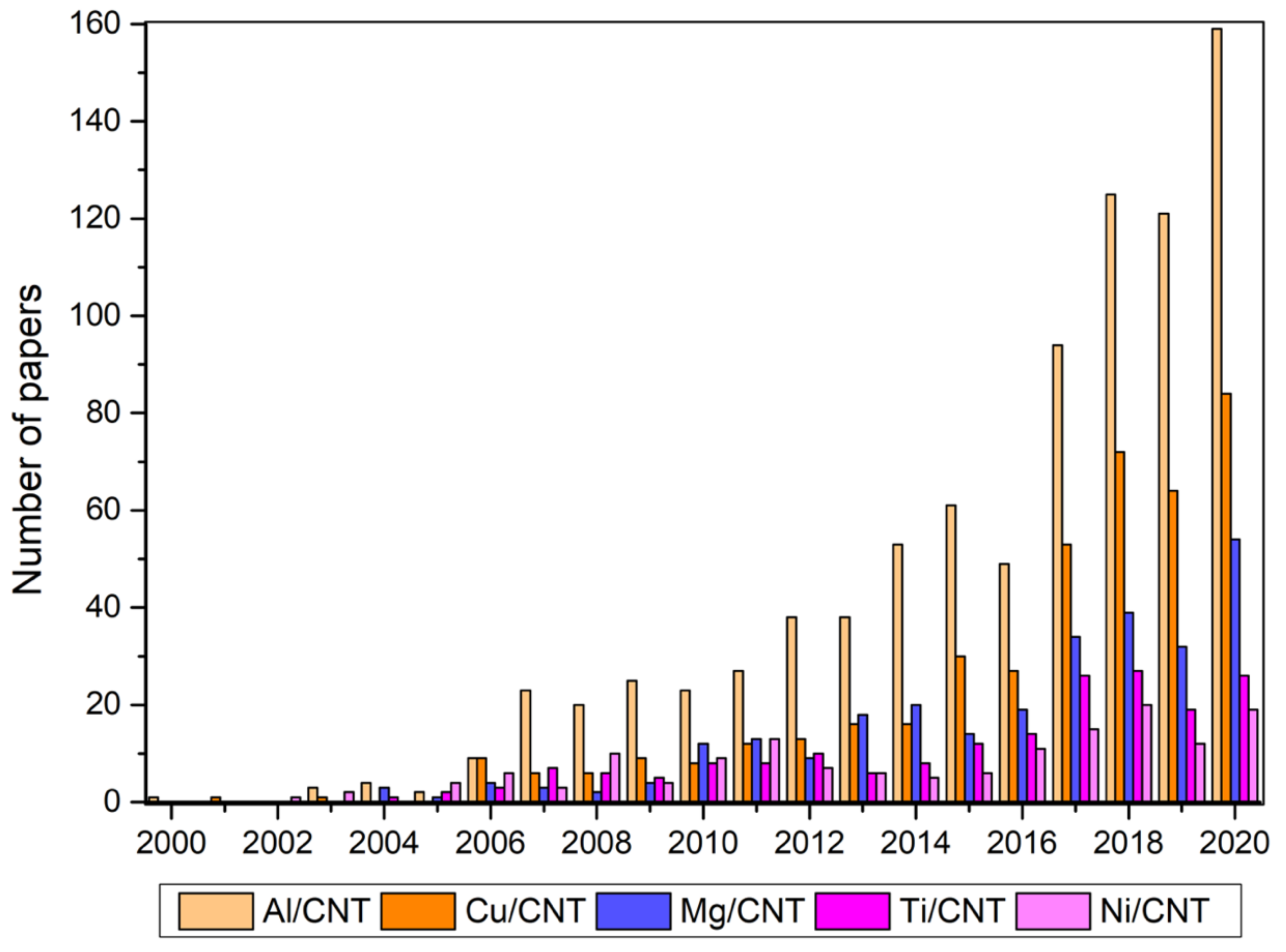
Figure 1. Evolution of the number of published papers, since 2000, on metal matrix composites reinforced by CNT.
Metals 11 01613 g001
Figure 2. Main production techniques used for MM/CNT.
Metals 11 01613 g002
Figure 3. Increase in hardness and tensile strength, based on mechanical properties and hardness values reported in papers published in recent years (data from [1,2,3,4,5,6,7,8,9,10,11,12,13,14,15,16,17,18,19,20,21,22,23,24,25,26,27,28,29,30,31,32,33,34,35,36,37,38,39,40,41,42,43,44]), obtained for different metal matrix composites reinforced with CNTs produced by different processing and CNT dispersion techniques.
Metals 11 01613 g003
Figure 4. (a) Tensile test curves from extruded raw Al and Al/CNT composites and SEM images of (b) the fracture surface of the Al-0.2 wt.% CNT composite after tensile testing, showing some pulled out and fractured CNTs. (c) High magnification of pulled out CNTs, (d) the CNT cluster in the fracture surface of the Al/0.3 wt.% CNT composite after tensile testing. (e) The remaining CNTs after etching away the Al in an acidic solution and filtering. Reproduced from [68] with permission from Elsevier, 2015.
Metals 11 01613 g004
Figure 5. SEM images of the surface fracture of Al/CNT nanocomposites produced with (a) 0.5 and (b) 1.0 wt.% of large-aspect ratio CNTs and (c) 0.5 and (d) 1.0 wt.% of small-aspect ratio CNTs. Reproduced from [72] with permission from Elsevier, 2021.
Metals 11 01613 g005
Figure 6. Schematic of the CNT behavior in the MM/CNT during tensile testing.
Metals 11 01613 g006
Figure 7. SEM images of the fracture process of the CNTs observed during the in situ tensile test: (a) CNT acting as a bridge, (b,c) CNTs marked as 1, 2 and 3 showing the different fracture processes at different magnifications, (d) fracture surface of the composite after tensile test, and (e) schematic representation of the different fractures. Adapted from [69] with permission from Elsevier, 2015.
Metals 11 01613 g007
Figure 8. Effect of the CNT failure mode on the strengthening efficiency (R) of composites as a function of interfacial stress (t) between CNT and matrix based on shear–lag model. Load transfer strengthening in carbon nanotube-reinforced metal matrix composites via in situ tensile tests; σm is the matrix yield strength; σf is the CNT yield strength and S is the aspect ratio of the CNT. Reproduced from [69] with permission from Elsevier, 2015.
Metals 11 01613 g008
Figure 9. Schematic of a CNT lying on the crack plane partially detached from the matrix. Adapted from [79] with permission from Elsevier, 2016.
Metals 11 01613 g009
Figure 10. HRTEM images of the interface between the CNT and metal matrix (a) before and (b,c) after the tensile test. Adapted from [79] with permission from Elsevier, 2016.
Metals 11 01613 g010
Figure 11. Schematic of the CNTs’ influence during the grain growth of the metal matrix, showing that the grain boundary motion as affected by CNT pinning and rotation induces a final microstructure with a different grain size or/and orientation.
Metals 11 01613 g011
Figure 12. Grain size maps obtained by EBSD for the sintered samples: (a) Pure Ni, (b) MWCNT/Ni 6.5 vol.%, (c) MWCNT/Ni 12 vol.%, (d) MWCNT/Ni 18 vol.%, and (e) MWCNT/Ni 27 vol.%. Reproduced from [87] with permission from Elsevier, 2014.
Metals 11 01613 g012
Figure 13. Inverse pole figure (IPF) maps obtained by EBSD for the sintered samples: (a) Pure Ni, (b) MWCNT/Ni 6.5 vol.%, (c) MWCNT/Ni 12 vol.%, (d) MWCNT/Ni 18 vol.%, and (e) MWCNT/Ni 27 vol.%. Reproduced from [88] with permission from Elsevier, 2013.
Metals 11 01613 g013
Figure 14. TEM observations of a composite Al/CNT produced at 875 K: (a) bright-field image, (b) dark-field image corresponding to (a); (c) selected area electron diffraction (SAED) patterns of (b); (d,e) high-magnification images and (f,g,h) inverse fast Fourier transform (FFT) images. Adapted from [74] with permission from Elsevier, 2017.
Metals 11 01613 g014
Figure 15. (a) TEM image showing the Al4C3 in the matrix; (b) and (c) TEM images and SAED of an Al4C3 particle, and (d) HRTEM image of Al4C3. Adapted from [94] with permission from John Wiley and Sons, 2014.
Metals 11 01613 g015
Figure 16. TEM and HRTEM images and FFT of 6061Al/CNT, showing the presence of dispersed CNT and Al4C3 and Mg2Si phases. (a) 6061Al-T6 sample, (b,c) 0.5 wt.% CNT/6061Al-T6 sample and (d,e) 1.5 wt.% CNT/6061Al-T6 sample, (f) HRTEM image of a CNT present in (e), (g) HRTEM image of an Al4C3 particle present in (e), (h) HRTEM image and respective (l) FFT patterns of Mg2Si precipitate present in (e). The black arrows indicate the Mg2Si precipitate. Reproduced from [98] with permission from Elsevier, 2019.
Metals 11 01613 g016
Figure 17. Schematic representation of the interaction between the dislocations, the CNTs and second phase particles.
Metals 11 01613 g017
Figure 18. TEM analyses of Al/1%CNTs@BM24h (a,b) and Al/1%CNTs@MC (c,d) composites after tensile tests. (a) and (c) are high-resolution TEM images. (b) and (d) are inverse FFT images of the box areas in (a) and (c), respectively. Reproduced from [99] with permission from Elsevier, 2017.
Metals 11 01613 g018
Figure 19. (a) Illustration of the microstructure of Al/CNT composites; (b) bright-field scanning TEM (STEM) image of an Al grain in 2% Al/CNT after break; (c) illustration of the dislocation behavior. Reproduced from [101] with permission from Elsevier, 2019.
Metals 11 01613 g019
Figure 20. EBSD (a,b) grain size maps, (b,e) image quality with delineated high- and low-angle boundaries (black and red, respectively), and (c,f) estimated geometrically necessary dislocations (GND) map of (a,b,c) Ni and (d,e,f) Ni/CNT nanocomposites.
Metals 11 01613 g020
Figure 21. In situ TEM observation of Al-CNT composites at different temperatures: (a) temperature-time curve; (bf) recorded TEM images during the stages in (a) as marked by corresponding capital letters. Adapted from [105] with permission from Elsevier, 2020.
Metals 11 01613 g021
Figure 22. (a) A schematic showing the Orowan looping mechanism after dislocations gliding over and bypassing the CNTs, and (b) the individual contribution of the strengthening mechanisms in the nanocomposite as a function of volume fraction. Reproduced from [106] with permission from Elsevier, 2021.
Metals 11 01613 g022
Figure 23. (a) Calculated yield strength contribution from grain refinement, dislocation strengthening, Orowan strengthening, and load transfers strengthening; (b) and (c) illustration of the origin of the strengthening mechanisms in a 6061 alloy and 6061Al/CNT composites. Adapted from [98] with permission from Elsevier, 2019.
Metals 11 01613 g023
Publisher’s Note: MDPI stays neutral with regard to jurisdictional claims in published maps and institutional affiliations.